EP3594044B1 - Kapazitives kraftfahrzeugbediensystem - Google Patents
Kapazitives kraftfahrzeugbediensystem Download PDFInfo
- Publication number
- EP3594044B1 EP3594044B1 EP19184508.0A EP19184508A EP3594044B1 EP 3594044 B1 EP3594044 B1 EP 3594044B1 EP 19184508 A EP19184508 A EP 19184508A EP 3594044 B1 EP3594044 B1 EP 3594044B1
- Authority
- EP
- European Patent Office
- Prior art keywords
- pressure
- capacitive
- actuation device
- motor vehicle
- operating system
- Prior art date
- Legal status (The legal status is an assumption and is not a legal conclusion. Google has not performed a legal analysis and makes no representation as to the accuracy of the status listed.)
- Revoked
Links
- 230000003993 interaction Effects 0.000 claims description 116
- 230000005540 biological transmission Effects 0.000 claims description 77
- 230000003287 optical effect Effects 0.000 claims description 19
- 230000008859 change Effects 0.000 claims description 10
- 230000001939 inductive effect Effects 0.000 claims description 6
- 230000005355 Hall effect Effects 0.000 claims description 2
- 230000000007 visual effect Effects 0.000 claims description 2
- 238000001514 detection method Methods 0.000 description 9
- 230000007935 neutral effect Effects 0.000 description 7
- 239000011521 glass Substances 0.000 description 6
- 238000013459 approach Methods 0.000 description 4
- 230000036316 preload Effects 0.000 description 3
- XEEYBQQBJWHFJM-UHFFFAOYSA-N Iron Chemical compound [Fe] XEEYBQQBJWHFJM-UHFFFAOYSA-N 0.000 description 2
- 230000006698 induction Effects 0.000 description 2
- 239000000463 material Substances 0.000 description 2
- 239000002184 metal Substances 0.000 description 2
- 229910052751 metal Inorganic materials 0.000 description 2
- 230000009471 action Effects 0.000 description 1
- 239000000853 adhesive Substances 0.000 description 1
- 230000001070 adhesive effect Effects 0.000 description 1
- 230000000994 depressogenic effect Effects 0.000 description 1
- 230000004907 flux Effects 0.000 description 1
- 229910052742 iron Inorganic materials 0.000 description 1
- 238000004519 manufacturing process Methods 0.000 description 1
- 238000005096 rolling process Methods 0.000 description 1
Images


Classifications
-
- G—PHYSICS
- G06—COMPUTING; CALCULATING OR COUNTING
- G06F—ELECTRIC DIGITAL DATA PROCESSING
- G06F3/00—Input arrangements for transferring data to be processed into a form capable of being handled by the computer; Output arrangements for transferring data from processing unit to output unit, e.g. interface arrangements
- G06F3/01—Input arrangements or combined input and output arrangements for interaction between user and computer
- G06F3/016—Input arrangements with force or tactile feedback as computer generated output to the user
-
- H—ELECTRICITY
- H03—ELECTRONIC CIRCUITRY
- H03K—PULSE TECHNIQUE
- H03K17/00—Electronic switching or gating, i.e. not by contact-making and –breaking
- H03K17/94—Electronic switching or gating, i.e. not by contact-making and –breaking characterised by the way in which the control signals are generated
- H03K17/96—Touch switches
- H03K17/962—Capacitive touch switches
-
- B—PERFORMING OPERATIONS; TRANSPORTING
- B60—VEHICLES IN GENERAL
- B60K—ARRANGEMENT OR MOUNTING OF PROPULSION UNITS OR OF TRANSMISSIONS IN VEHICLES; ARRANGEMENT OR MOUNTING OF PLURAL DIVERSE PRIME-MOVERS IN VEHICLES; AUXILIARY DRIVES FOR VEHICLES; INSTRUMENTATION OR DASHBOARDS FOR VEHICLES; ARRANGEMENTS IN CONNECTION WITH COOLING, AIR INTAKE, GAS EXHAUST OR FUEL SUPPLY OF PROPULSION UNITS IN VEHICLES
- B60K35/00—Instruments specially adapted for vehicles; Arrangement of instruments in or on vehicles
- B60K35/10—Input arrangements, i.e. from user to vehicle, associated with vehicle functions or specially adapted therefor
-
- B—PERFORMING OPERATIONS; TRANSPORTING
- B60—VEHICLES IN GENERAL
- B60K—ARRANGEMENT OR MOUNTING OF PROPULSION UNITS OR OF TRANSMISSIONS IN VEHICLES; ARRANGEMENT OR MOUNTING OF PLURAL DIVERSE PRIME-MOVERS IN VEHICLES; AUXILIARY DRIVES FOR VEHICLES; INSTRUMENTATION OR DASHBOARDS FOR VEHICLES; ARRANGEMENTS IN CONNECTION WITH COOLING, AIR INTAKE, GAS EXHAUST OR FUEL SUPPLY OF PROPULSION UNITS IN VEHICLES
- B60K35/00—Instruments specially adapted for vehicles; Arrangement of instruments in or on vehicles
- B60K35/20—Output arrangements, i.e. from vehicle to user, associated with vehicle functions or specially adapted therefor
- B60K35/21—Output arrangements, i.e. from vehicle to user, associated with vehicle functions or specially adapted therefor using visual output, e.g. blinking lights or matrix displays
- B60K35/22—Display screens
-
- B—PERFORMING OPERATIONS; TRANSPORTING
- B60—VEHICLES IN GENERAL
- B60K—ARRANGEMENT OR MOUNTING OF PROPULSION UNITS OR OF TRANSMISSIONS IN VEHICLES; ARRANGEMENT OR MOUNTING OF PLURAL DIVERSE PRIME-MOVERS IN VEHICLES; AUXILIARY DRIVES FOR VEHICLES; INSTRUMENTATION OR DASHBOARDS FOR VEHICLES; ARRANGEMENTS IN CONNECTION WITH COOLING, AIR INTAKE, GAS EXHAUST OR FUEL SUPPLY OF PROPULSION UNITS IN VEHICLES
- B60K35/00—Instruments specially adapted for vehicles; Arrangement of instruments in or on vehicles
- B60K35/20—Output arrangements, i.e. from vehicle to user, associated with vehicle functions or specially adapted therefor
- B60K35/25—Output arrangements, i.e. from vehicle to user, associated with vehicle functions or specially adapted therefor using haptic output
-
- B—PERFORMING OPERATIONS; TRANSPORTING
- B60—VEHICLES IN GENERAL
- B60R—VEHICLES, VEHICLE FITTINGS, OR VEHICLE PARTS, NOT OTHERWISE PROVIDED FOR
- B60R11/00—Arrangements for holding or mounting articles, not otherwise provided for
- B60R11/02—Arrangements for holding or mounting articles, not otherwise provided for for radio sets, television sets, telephones, or the like; Arrangement of controls thereof
- B60R11/0229—Arrangements for holding or mounting articles, not otherwise provided for for radio sets, television sets, telephones, or the like; Arrangement of controls thereof for displays, e.g. cathodic tubes
- B60R11/0235—Arrangements for holding or mounting articles, not otherwise provided for for radio sets, television sets, telephones, or the like; Arrangement of controls thereof for displays, e.g. cathodic tubes of flat type, e.g. LCD
-
- B—PERFORMING OPERATIONS; TRANSPORTING
- B60—VEHICLES IN GENERAL
- B60R—VEHICLES, VEHICLE FITTINGS, OR VEHICLE PARTS, NOT OTHERWISE PROVIDED FOR
- B60R11/00—Arrangements for holding or mounting articles, not otherwise provided for
- B60R11/02—Arrangements for holding or mounting articles, not otherwise provided for for radio sets, television sets, telephones, or the like; Arrangement of controls thereof
- B60R11/0264—Arrangements for holding or mounting articles, not otherwise provided for for radio sets, television sets, telephones, or the like; Arrangement of controls thereof for control means
-
- G—PHYSICS
- G01—MEASURING; TESTING
- G01D—MEASURING NOT SPECIALLY ADAPTED FOR A SPECIFIC VARIABLE; ARRANGEMENTS FOR MEASURING TWO OR MORE VARIABLES NOT COVERED IN A SINGLE OTHER SUBCLASS; TARIFF METERING APPARATUS; MEASURING OR TESTING NOT OTHERWISE PROVIDED FOR
- G01D5/00—Mechanical means for transferring the output of a sensing member; Means for converting the output of a sensing member to another variable where the form or nature of the sensing member does not constrain the means for converting; Transducers not specially adapted for a specific variable
- G01D5/12—Mechanical means for transferring the output of a sensing member; Means for converting the output of a sensing member to another variable where the form or nature of the sensing member does not constrain the means for converting; Transducers not specially adapted for a specific variable using electric or magnetic means
- G01D5/14—Mechanical means for transferring the output of a sensing member; Means for converting the output of a sensing member to another variable where the form or nature of the sensing member does not constrain the means for converting; Transducers not specially adapted for a specific variable using electric or magnetic means influencing the magnitude of a current or voltage
- G01D5/142—Mechanical means for transferring the output of a sensing member; Means for converting the output of a sensing member to another variable where the form or nature of the sensing member does not constrain the means for converting; Transducers not specially adapted for a specific variable using electric or magnetic means influencing the magnitude of a current or voltage using Hall-effect devices
-
- G—PHYSICS
- G01—MEASURING; TESTING
- G01D—MEASURING NOT SPECIALLY ADAPTED FOR A SPECIFIC VARIABLE; ARRANGEMENTS FOR MEASURING TWO OR MORE VARIABLES NOT COVERED IN A SINGLE OTHER SUBCLASS; TARIFF METERING APPARATUS; MEASURING OR TESTING NOT OTHERWISE PROVIDED FOR
- G01D5/00—Mechanical means for transferring the output of a sensing member; Means for converting the output of a sensing member to another variable where the form or nature of the sensing member does not constrain the means for converting; Transducers not specially adapted for a specific variable
- G01D5/12—Mechanical means for transferring the output of a sensing member; Means for converting the output of a sensing member to another variable where the form or nature of the sensing member does not constrain the means for converting; Transducers not specially adapted for a specific variable using electric or magnetic means
- G01D5/14—Mechanical means for transferring the output of a sensing member; Means for converting the output of a sensing member to another variable where the form or nature of the sensing member does not constrain the means for converting; Transducers not specially adapted for a specific variable using electric or magnetic means influencing the magnitude of a current or voltage
- G01D5/20—Mechanical means for transferring the output of a sensing member; Means for converting the output of a sensing member to another variable where the form or nature of the sensing member does not constrain the means for converting; Transducers not specially adapted for a specific variable using electric or magnetic means influencing the magnitude of a current or voltage by varying inductance, e.g. by a movable armature
- G01D5/22—Mechanical means for transferring the output of a sensing member; Means for converting the output of a sensing member to another variable where the form or nature of the sensing member does not constrain the means for converting; Transducers not specially adapted for a specific variable using electric or magnetic means influencing the magnitude of a current or voltage by varying inductance, e.g. by a movable armature differentially influencing two coils
-
- G—PHYSICS
- G01—MEASURING; TESTING
- G01D—MEASURING NOT SPECIALLY ADAPTED FOR A SPECIFIC VARIABLE; ARRANGEMENTS FOR MEASURING TWO OR MORE VARIABLES NOT COVERED IN A SINGLE OTHER SUBCLASS; TARIFF METERING APPARATUS; MEASURING OR TESTING NOT OTHERWISE PROVIDED FOR
- G01D5/00—Mechanical means for transferring the output of a sensing member; Means for converting the output of a sensing member to another variable where the form or nature of the sensing member does not constrain the means for converting; Transducers not specially adapted for a specific variable
- G01D5/26—Mechanical means for transferring the output of a sensing member; Means for converting the output of a sensing member to another variable where the form or nature of the sensing member does not constrain the means for converting; Transducers not specially adapted for a specific variable characterised by optical transfer means, i.e. using infrared, visible, or ultraviolet light
- G01D5/32—Mechanical means for transferring the output of a sensing member; Means for converting the output of a sensing member to another variable where the form or nature of the sensing member does not constrain the means for converting; Transducers not specially adapted for a specific variable characterised by optical transfer means, i.e. using infrared, visible, or ultraviolet light with attenuation or whole or partial obturation of beams of light
- G01D5/34—Mechanical means for transferring the output of a sensing member; Means for converting the output of a sensing member to another variable where the form or nature of the sensing member does not constrain the means for converting; Transducers not specially adapted for a specific variable characterised by optical transfer means, i.e. using infrared, visible, or ultraviolet light with attenuation or whole or partial obturation of beams of light the beams of light being detected by photocells
- G01D5/347—Mechanical means for transferring the output of a sensing member; Means for converting the output of a sensing member to another variable where the form or nature of the sensing member does not constrain the means for converting; Transducers not specially adapted for a specific variable characterised by optical transfer means, i.e. using infrared, visible, or ultraviolet light with attenuation or whole or partial obturation of beams of light the beams of light being detected by photocells using displacement encoding scales
- G01D5/3473—Circular or rotary encoders
-
- G—PHYSICS
- G06—COMPUTING; CALCULATING OR COUNTING
- G06F—ELECTRIC DIGITAL DATA PROCESSING
- G06F3/00—Input arrangements for transferring data to be processed into a form capable of being handled by the computer; Output arrangements for transferring data from processing unit to output unit, e.g. interface arrangements
- G06F3/01—Input arrangements or combined input and output arrangements for interaction between user and computer
- G06F3/017—Gesture based interaction, e.g. based on a set of recognized hand gestures
-
- G—PHYSICS
- G06—COMPUTING; CALCULATING OR COUNTING
- G06F—ELECTRIC DIGITAL DATA PROCESSING
- G06F3/00—Input arrangements for transferring data to be processed into a form capable of being handled by the computer; Output arrangements for transferring data from processing unit to output unit, e.g. interface arrangements
- G06F3/01—Input arrangements or combined input and output arrangements for interaction between user and computer
- G06F3/03—Arrangements for converting the position or the displacement of a member into a coded form
- G06F3/033—Pointing devices displaced or positioned by the user, e.g. mice, trackballs, pens or joysticks; Accessories therefor
- G06F3/0354—Pointing devices displaced or positioned by the user, e.g. mice, trackballs, pens or joysticks; Accessories therefor with detection of 2D relative movements between the device, or an operating part thereof, and a plane or surface, e.g. 2D mice, trackballs, pens or pucks
- G06F3/03547—Touch pads, in which fingers can move on a surface
-
- G—PHYSICS
- G06—COMPUTING; CALCULATING OR COUNTING
- G06F—ELECTRIC DIGITAL DATA PROCESSING
- G06F3/00—Input arrangements for transferring data to be processed into a form capable of being handled by the computer; Output arrangements for transferring data from processing unit to output unit, e.g. interface arrangements
- G06F3/01—Input arrangements or combined input and output arrangements for interaction between user and computer
- G06F3/03—Arrangements for converting the position or the displacement of a member into a coded form
- G06F3/033—Pointing devices displaced or positioned by the user, e.g. mice, trackballs, pens or joysticks; Accessories therefor
- G06F3/0362—Pointing devices displaced or positioned by the user, e.g. mice, trackballs, pens or joysticks; Accessories therefor with detection of 1D translations or rotations of an operating part of the device, e.g. scroll wheels, sliders, knobs, rollers or belts
-
- G—PHYSICS
- G06—COMPUTING; CALCULATING OR COUNTING
- G06F—ELECTRIC DIGITAL DATA PROCESSING
- G06F3/00—Input arrangements for transferring data to be processed into a form capable of being handled by the computer; Output arrangements for transferring data from processing unit to output unit, e.g. interface arrangements
- G06F3/01—Input arrangements or combined input and output arrangements for interaction between user and computer
- G06F3/03—Arrangements for converting the position or the displacement of a member into a coded form
- G06F3/033—Pointing devices displaced or positioned by the user, e.g. mice, trackballs, pens or joysticks; Accessories therefor
- G06F3/039—Accessories therefor, e.g. mouse pads
- G06F3/0393—Accessories for touch pads or touch screens, e.g. mechanical guides added to touch screens for drawing straight lines, hard keys overlaying touch screens or touch pads
-
- G—PHYSICS
- G06—COMPUTING; CALCULATING OR COUNTING
- G06F—ELECTRIC DIGITAL DATA PROCESSING
- G06F3/00—Input arrangements for transferring data to be processed into a form capable of being handled by the computer; Output arrangements for transferring data from processing unit to output unit, e.g. interface arrangements
- G06F3/01—Input arrangements or combined input and output arrangements for interaction between user and computer
- G06F3/03—Arrangements for converting the position or the displacement of a member into a coded form
- G06F3/041—Digitisers, e.g. for touch screens or touch pads, characterised by the transducing means
- G06F3/0414—Digitisers, e.g. for touch screens or touch pads, characterised by the transducing means using force sensing means to determine a position
-
- G—PHYSICS
- G06—COMPUTING; CALCULATING OR COUNTING
- G06F—ELECTRIC DIGITAL DATA PROCESSING
- G06F3/00—Input arrangements for transferring data to be processed into a form capable of being handled by the computer; Output arrangements for transferring data from processing unit to output unit, e.g. interface arrangements
- G06F3/01—Input arrangements or combined input and output arrangements for interaction between user and computer
- G06F3/03—Arrangements for converting the position or the displacement of a member into a coded form
- G06F3/041—Digitisers, e.g. for touch screens or touch pads, characterised by the transducing means
- G06F3/044—Digitisers, e.g. for touch screens or touch pads, characterised by the transducing means by capacitive means
-
- G—PHYSICS
- G06—COMPUTING; CALCULATING OR COUNTING
- G06F—ELECTRIC DIGITAL DATA PROCESSING
- G06F3/00—Input arrangements for transferring data to be processed into a form capable of being handled by the computer; Output arrangements for transferring data from processing unit to output unit, e.g. interface arrangements
- G06F3/01—Input arrangements or combined input and output arrangements for interaction between user and computer
- G06F3/048—Interaction techniques based on graphical user interfaces [GUI]
- G06F3/0484—Interaction techniques based on graphical user interfaces [GUI] for the control of specific functions or operations, e.g. selecting or manipulating an object, an image or a displayed text element, setting a parameter value or selecting a range
- G06F3/04845—Interaction techniques based on graphical user interfaces [GUI] for the control of specific functions or operations, e.g. selecting or manipulating an object, an image or a displayed text element, setting a parameter value or selecting a range for image manipulation, e.g. dragging, rotation, expansion or change of colour
-
- G—PHYSICS
- G06—COMPUTING; CALCULATING OR COUNTING
- G06F—ELECTRIC DIGITAL DATA PROCESSING
- G06F3/00—Input arrangements for transferring data to be processed into a form capable of being handled by the computer; Output arrangements for transferring data from processing unit to output unit, e.g. interface arrangements
- G06F3/01—Input arrangements or combined input and output arrangements for interaction between user and computer
- G06F3/048—Interaction techniques based on graphical user interfaces [GUI]
- G06F3/0484—Interaction techniques based on graphical user interfaces [GUI] for the control of specific functions or operations, e.g. selecting or manipulating an object, an image or a displayed text element, setting a parameter value or selecting a range
- G06F3/0485—Scrolling or panning
-
- G—PHYSICS
- G06—COMPUTING; CALCULATING OR COUNTING
- G06F—ELECTRIC DIGITAL DATA PROCESSING
- G06F3/00—Input arrangements for transferring data to be processed into a form capable of being handled by the computer; Output arrangements for transferring data from processing unit to output unit, e.g. interface arrangements
- G06F3/01—Input arrangements or combined input and output arrangements for interaction between user and computer
- G06F3/048—Interaction techniques based on graphical user interfaces [GUI]
- G06F3/0487—Interaction techniques based on graphical user interfaces [GUI] using specific features provided by the input device, e.g. functions controlled by the rotation of a mouse with dual sensing arrangements, or of the nature of the input device, e.g. tap gestures based on pressure sensed by a digitiser
- G06F3/0488—Interaction techniques based on graphical user interfaces [GUI] using specific features provided by the input device, e.g. functions controlled by the rotation of a mouse with dual sensing arrangements, or of the nature of the input device, e.g. tap gestures based on pressure sensed by a digitiser using a touch-screen or digitiser, e.g. input of commands through traced gestures
- G06F3/04883—Interaction techniques based on graphical user interfaces [GUI] using specific features provided by the input device, e.g. functions controlled by the rotation of a mouse with dual sensing arrangements, or of the nature of the input device, e.g. tap gestures based on pressure sensed by a digitiser using a touch-screen or digitiser, e.g. input of commands through traced gestures for inputting data by handwriting, e.g. gesture or text
-
- B—PERFORMING OPERATIONS; TRANSPORTING
- B60—VEHICLES IN GENERAL
- B60K—ARRANGEMENT OR MOUNTING OF PROPULSION UNITS OR OF TRANSMISSIONS IN VEHICLES; ARRANGEMENT OR MOUNTING OF PLURAL DIVERSE PRIME-MOVERS IN VEHICLES; AUXILIARY DRIVES FOR VEHICLES; INSTRUMENTATION OR DASHBOARDS FOR VEHICLES; ARRANGEMENTS IN CONNECTION WITH COOLING, AIR INTAKE, GAS EXHAUST OR FUEL SUPPLY OF PROPULSION UNITS IN VEHICLES
- B60K2360/00—Indexing scheme associated with groups B60K35/00 or B60K37/00 relating to details of instruments or dashboards
- B60K2360/126—Rotatable input devices for instruments
-
- B—PERFORMING OPERATIONS; TRANSPORTING
- B60—VEHICLES IN GENERAL
- B60K—ARRANGEMENT OR MOUNTING OF PROPULSION UNITS OR OF TRANSMISSIONS IN VEHICLES; ARRANGEMENT OR MOUNTING OF PLURAL DIVERSE PRIME-MOVERS IN VEHICLES; AUXILIARY DRIVES FOR VEHICLES; INSTRUMENTATION OR DASHBOARDS FOR VEHICLES; ARRANGEMENTS IN CONNECTION WITH COOLING, AIR INTAKE, GAS EXHAUST OR FUEL SUPPLY OF PROPULSION UNITS IN VEHICLES
- B60K2360/00—Indexing scheme associated with groups B60K35/00 or B60K37/00 relating to details of instruments or dashboards
- B60K2360/143—Touch sensitive instrument input devices
- B60K2360/1438—Touch screens
-
- B—PERFORMING OPERATIONS; TRANSPORTING
- B60—VEHICLES IN GENERAL
- B60K—ARRANGEMENT OR MOUNTING OF PROPULSION UNITS OR OF TRANSMISSIONS IN VEHICLES; ARRANGEMENT OR MOUNTING OF PLURAL DIVERSE PRIME-MOVERS IN VEHICLES; AUXILIARY DRIVES FOR VEHICLES; INSTRUMENTATION OR DASHBOARDS FOR VEHICLES; ARRANGEMENTS IN CONNECTION WITH COOLING, AIR INTAKE, GAS EXHAUST OR FUEL SUPPLY OF PROPULSION UNITS IN VEHICLES
- B60K2360/00—Indexing scheme associated with groups B60K35/00 or B60K37/00 relating to details of instruments or dashboards
- B60K2360/145—Instrument input by combination of touch screen and hardware input devices
-
- H—ELECTRICITY
- H03—ELECTRONIC CIRCUITRY
- H03K—PULSE TECHNIQUE
- H03K2217/00—Indexing scheme related to electronic switching or gating, i.e. not by contact-making or -breaking covered by H03K17/00
- H03K2217/94—Indexing scheme related to electronic switching or gating, i.e. not by contact-making or -breaking covered by H03K17/00 characterised by the way in which the control signal is generated
- H03K2217/94057—Rotary switches
Definitions
- the invention relates to a capacitive motor vehicle operating system for the interior of a motor vehicle.
- Motor vehicle operating systems are known from the prior art with which functions of a motor vehicle can be switched on or off, for example a multimedia system of a motor vehicle.
- the motor vehicle operating systems usually comprise operating elements formed by mechanical switches and the like, which are pressed or rotated by a vehicle occupant in order to activate or deactivate an assigned function.
- capacitive motor vehicle operating systems with correspondingly capacitive operating elements are also known, which detect an approach or a touch, whereupon the motor vehicle operating system performs an assigned function.
- the capacitive motor vehicle operating systems known from the prior art however, have a relatively complex structure, as a result of which the production costs are correspondingly high.
- capacitive screens for controlling vehicle functions are known, on which corresponding switch symbols or buttons are displayed which a vehicle occupant can touch or approach in order to perform an assigned function.
- so-called sliding areas are also known, along which the operator of the motor vehicle control system can slide his finger, for example, in order to set a function continuously or in steps.
- the corresponding function can be a volume control of a multimedia system, in which the operator of the motor vehicle control system moves his finger along an area displayed on the capacitive user interface of the capacitive screen in order to set the desired volume.
- the FR 3 056 475 A1 , the FR 3 056 474 A1 and the FR 3 058 938 A1 disclose a motor vehicle operating system that has a touchscreen and a rotatable control element mounted on the touchscreen, a rotation of the control element being capacitively detected by the touchscreen.
- FR 3 035 981 A1 describes a rotary switch in a motor vehicle, which is arranged on a touch screen.
- the DE 10 2015 002 300 A1 shows an input device which is attached laterally displaceably to a holder, the holder being attached to an input device in the form of a touchscreen.
- the object of the invention is to provide a simply constructed and easy to use motor vehicle control system.
- a capacitive motor vehicle operating system comprising a capacitive screen with a user interface and a pressure and rotary actuation device which is designed separately from the capacitive screen and which is electrically conductive in areas and is at least partially attached to the user interface of the capacitive screen, with the pressure - and rotary actuation device comprises at least one electrically conductive interaction element that interacts with the capacitive screen.
- a pressure actuation takes place essentially parallel to an axis of rotation in the direction of the capacitive screen.
- the pressure and rotary actuation device when the pressure and rotary actuation device is actuated, there is an electrical connection between the user interface of the capacitive screen and a rotatable actuating element of the pressure and rotary actuation device.
- the electrical connection is provided via the at least one electrically conductive interaction element that contacts the user interface when it is actuated.
- the pressure and rotary actuation device is annular.
- the motor vehicle operating system is designed to have at least one pressure actuation of the pressure and rotary actuation device by means of the capacitive To capture the screen in a capacitive manner.
- the entire pressure and rotary actuation device is laterally immobile in a plane spanned by the screen.
- the basic idea of the invention is that an electrical connection between the operator of the motor vehicle operating system and the capacitive screen, in particular the user interface, is established when the operator touches or approaches the at least partially electrically conductive pressure and rotary actuation device, whereby an electrical Connection between the operator and the capacitive screen is established via the separately designed pressure and rotary actuation device.
- the pressure and rotary actuator is at least partially attached to the user interface of the capacitive screen, it is not possible for the entire pressure and rotary actuator to be moved over the capacitive screen, in particular its user interface, in order to perform a corresponding function on the screen.
- the pressure and rotary actuation device is arranged in a stationary manner on the capacitive screen, since it always takes up the same area on the capacitive screen regardless of the action.
- volume control can be carried out via the rotary actuation of the pressure and rotary actuation device, or an address book is scrolled through in this way.
- the pressure and rotary actuation device can be glued onto the capacitive screen in a simple manner, as a result of which it is correspondingly fixed in place on the capacitive screen.
- the capacitive screen is set up in the usual way, so that it shows the position and / or the movement of the at least one electrically conductive interaction element of the pressure and rotary actuation device in relation to the Capacitive screen detects if there is contact with the capacitive screen, and outputs corresponding signals that are converted into corresponding functions, for example by a higher-level control and / or arithmetic unit.
- separately designed interaction elements can be provided for the pressure actuation and the rotary actuation of the pressure and rotary actuation device, that is to say at least one pressure actuation interaction element and at least one rotary actuation interaction element.
- the pressure and rotary actuation device provides haptic feedback when actuated.
- the entire pressure and rotary actuation device is laterally immobile in a plane spanned by the screen.
- the pressure and rotary actuation device can have a stationary base, in particular with regard to the capacitive screen.
- the pressure and rotary actuation device is fastened, for example, via the stationary base on the capacitive screen, in particular in such a way that the entire pressure and rotary actuation device is laterally immovable in a plane spanned by the screen.
- the pressure and rotary actuation device can have an actuating element, in particular an annular actuating element, which is adjustable. A rotation of the adjustable actuating element in relation to the base is therefore possible in order to realize the rotary actuation.
- the pressure and rotary actuation device can be rotated about an axis of rotation which is essentially perpendicular to the surface of the capacitive screen.
- the pressure actuation therefore takes place essentially parallel to the axis of rotation, that is to say in the direction of the capacitive screen.
- the capacitive screen recognizes via the electrical connection that the pressure and rotary actuation device is being operated by the operator of the motor vehicle operating system.
- the electrical connection made can be viewed as a trigger signal or trigger signal for the motor vehicle operating system.
- the electrical connection is provided via the at least one electrically conductive interaction element that contacts the user interface when actuated.
- the electrically conductive interaction element can be moved over the user interface, the capacitive screen recognizing the movement accordingly.
- the capacitive screen can also be set up to detect the area, that is to say the size of the area, and / or different positions on the user interface that are contacted by the interaction element when the pressure and rotary actuation device is actuated in order to access a corresponding Operation of the push and turn control device to close.
- a pressure actuation of the pressure and rotary actuation device leads to a large surface contact between the interaction element and the user interface, which is recognized by the capacitive screen as a pressure actuation, so that a function linked to the pressure actuation is carried out.
- a simply structured motor vehicle operating system which capacitively detects a corresponding pressure actuation, for which purpose the pressure and rotary actuation device is electrically conductive in some areas in order to interact with the capacitive screen. It is therefore not necessary for the operator to touch the capacitive screen.
- the at least one interaction element comprises several sections which can be actuated separately from one another and via which the angle of rotation of the pressure and rotary actuation device can be detected, in particular wherein the several sections each include a haptic feedback structure.
- the plurality of interaction elements are on the surface associated with the pressure and rotary actuation device capacitive screen arranged distributed. Depending on the actuation of the pressure and rotary actuation device, there is thus a different contact on the capacitive screen through the multiple interaction elements.
- the rotary actuation in particular the angle of rotation
- the time sequence of the respective contacting of the capacitive screen by the multiple interaction elements can be taken into account.
- electrically conductive sections of an interaction element can be provided, for example a sheet metal with corresponding segments or sections that are adjusted relative to the capacitive screen in order to contact the capacitive screen depending on the actuation of the pressure and rotary actuation device. This then creates an electrical connection with the capacitive screen, which is accordingly detected by the capacitive screen.
- the sections of the (one-piece interaction element) can each comprise a haptic feedback structure which provides a corresponding tactile feedback to the operator when the pressure and rotary actuation device is rotated.
- the pressure and rotary actuation device can have at least one force transmission element which interacts with the interaction element.
- the force transmission element can be a rollable force transmission element, for example a ball, which can be moved relative to the user interface when the pressure and rotary actuation device is rotated.
- the force transmission element can be moved relative to the at least one interaction element, it adjusting the at least one interaction element in a direction perpendicular to the user interface of the capacitive screen when it is moved via the at least one interaction element due to the rotary actuation of the pressure and rotary actuation device.
- the power transmission member move via the (one-piece) interaction element when the pressure and rotary actuation device is rotated, whereby it adjusts the sections that can be actuated individually and separately from one another relative to the capacitive screen.
- a plurality of force transmission members can also be provided in order to ensure homogeneous or uniform rotary actuation of the pressure and rotary actuation device.
- the plurality of force transmission members are preferably substantially equally spaced from one another.
- the force transmission element can also be the interaction element at the same time, provided that the force transmission element is electrically conductive.
- the force transmission element can be an electrically conductive (and optionally elastic) ball.
- the force transmission element can be electrically conductive, provided that the electrical connection from the rotatable actuating element to the user interface of the capacitive screen is established via the force transmission element.
- the at least one interaction element can experience a change in position relative to the user interface of the capacitive screen when the pressure and rotary actuation device is actuated.
- the actuation of the pressure and rotary actuation device thus ensures that the at least one interaction element is adjusted relative to the user interface of the capacitive screen, which is accordingly detected by the capacitive screen. If the at least one interaction element is moved over the capacitive screen, a relative change in position takes place via the rotational movement of the interaction element.
- the relative change in position takes place in a plane perpendicular to the user interface of the capacitive screen. This is the case in particular when the pressure and rotary actuation device is actuated by pressure.
- a change in position of the at least one interaction element that is perpendicular to the user interface can also occur when the pressure and rotary actuation device is rotated.
- several (in plan view and in relation to the Fixed screen) interaction elements are provided, which are assigned to different regions of the capacitive screen, whereby a location and / or time-resolved detection of the contacting of the plurality of interaction elements takes place.
- the plurality of interaction elements can be adjusted independently of one another by the at least one force transmission element perpendicular to the plane spanned by the capacitive screen when the force transmission element interacts with the corresponding interaction element.
- the at least one interaction element is formed by at least one magnet.
- the electrical connection can be established accordingly in a simple manner via the magnet.
- the interaction element can then be adjusted electromagnetically.
- several magnets are provided that interact electromagnetically with one another.
- the plurality of magnets can be arranged in two planes, the magnets of both planes interacting with one another.
- One plane of the magnets can be rotated relative to the other plane of the magnets when the pressure and rotary actuation device is rotated, so that different poles of the magnets are opposite each other, which leads to a repulsive electromagnetic force, whereby electrical contact is made with the capacitive screen.
- the at least one interaction element is elastically, mechanically pretensioned and / or electromagnetically pretensioned. This makes it possible for the pressure and rotary actuation device to return to a neutral position when the operator no longer exerts any force, that is to say after the pressure and rotary actuation device has been actuated.
- haptic feedback can be generated for the operator of the motor vehicle operating system via the preload.
- the preload can be used to ensure that the at least one interaction element remains in the desired position. If the interaction element is elastic, the interaction element thus has an inherent pretension.
- the preload can provide a safety function, since the capacitive screen is not damaged when the push-and-turn actuation device is actuated.
- the at least one interaction element is formed by an electrically conductive ball, which is, for example, additionally elastic.
- the electrically conductive ball When the pressure and rotary control device is actuated in a rotary manner, the electrically conductive ball generates a corresponding electrical connection on the capacitive screen, as a result of which the actuation of the pressure and rotary control device is detected by the capacitive screen.
- the elasticity also ensures that tactile feedback occurs, which is also referred to as haptic feedback.
- the pressure and rotary actuation device can comprise at least two electrically conductive sections which serve as interaction elements and are provided at different positions in relation to the capacitive screen.
- the electrically conductive sections can interact with at least one (electrically conductive) force transmission member. With a rotary actuation of the pressure and rotary actuation device, the two electrically conductive sections are thus actuated at different times (via the at least one force transmission element), whereby the direction of movement of the pressure and rotary actuation device can be determined during a rotary actuation.
- the motor vehicle operating system can comprise a rotary encoder, via which the angle of rotation of the pressure and rotary actuation device can be detected during a rotary actuation.
- the rotary encoder also called encoder, can be designed in different ways.
- the rotary encoder comprises an optical sensor, a Hall sensor and / or an inductive coil. Accordingly, in addition to the capacitive manner, the rotary encoder can also be provided in an optical and / or electromagnetic manner.
- the at least one electrically conductive interaction element can therefore only be used for pressure actuation of the pressure and rotary actuation device, since the rotary actuation of the pressure and rotary actuation device is detected by the rotary encoder, in particular in an optical and / or electromagnetic manner.
- the capacitive screen can have at least one display area which is assigned to the pressure and rotary actuation device and, when the pressure and rotary actuation device is actuated, outputs a visual feedback. Accordingly, the capacitive motor vehicle operating system is designed at the same time to provide optical (and tactile) feedback, so that the operator of the capacitive motor vehicle operating system immediately receives a corresponding feedback.
- the pressure and rotary actuating device comprises a stationary base and an actuating element that can be adjusted relative to the base.
- the stationary base is attached to the capacitive screen, in particular glued to the capacitive screen.
- the adjustable actuating element is moved relative to the stationary base during a rotary or pressure actuation. In the case of a rotary actuation, a rotation of the adjustable actuating element therefore results in relation to the base.
- the adjustable actuating element is designed in particular to be electrically conductive.
- the pressure and rotary actuation device can comprise an electrically conductive interaction element which is provided for the pressure actuation of the pressure and rotary actuation device.
- the pressure and rotary actuation device can comprise an electrically conductive interaction element which is provided for the rotary actuation of the pressure and rotary actuation device.
- the electrically conductive interaction element can move over the user interface or in a direction perpendicular thereto, in particular when the electrically conductive interaction element interacts with a force transmission member.
- the rotary actuation of the pressure and rotary actuation device is detected via a rotary encoder or an encoder, for example in a capacitive, optical and / or electromagnetic manner, i.e. due to induction and / or due to the Hall effect.
- the at least one force transmission element serves in particular to transmit or translate a rotational force into a lateral force, in that the force transmission element interacts, for example, with the electrically conductive interaction element and adjusts it.
- the capacitive screen is a display field on which content can be displayed, in particular on the basis of electrical control signals.
- the capacitive screen is also designed to be touch-sensitive or proximity-sensitive.
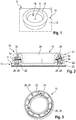
- FIG. 1 a capacitive motor vehicle operating system 10 is shown, which is used in an interior of a motor vehicle in order, for example, to control a multimedia system and / or vehicle functions of a motor vehicle.
- the capacitive motor vehicle operating system 10 comprises a capacitive screen 12, which has a user interface 14, so that a touch of the user interface 14 or an approach to the user interface 14 can be capacitively detected.
- the capacitive motor vehicle operating system 10 comprises a pressure and rotary actuation device 16, which is formed separately from the capacitive screen 12.
- the pressure and rotary actuation device 16 is essentially annular, the pressure and rotary actuation device 16 being arranged at least partially on the user interface 14 of the capacitive screen 12. This means that the pressure and rotary actuation device 16 occupies a partial area of the user interface 14.
- the pressure and rotary actuation device 16 is attached to the capacitive screen 12 in that the pressure and rotary actuation device 16 is glued, for example, to the capacitive screen 12, as will be explained below.
- the pressure and rotary actuation device 16 is arranged essentially stationary with respect to the capacitive screen 12. This means that the entire pressure and rotary actuation device 16 cannot be shifted on the capacitive screen 12, that is to say it can be moved laterally in the plane spanned by the capacitive screen 12, which corresponds to the user interface 14.
- the pressure and rotary actuation device 16 is designed to be electrically conductive in some areas, so that an electrical connection can be established via the pressure and rotary actuation device 16 to the capacitive screen 12 when an operator of the motor vehicle operating system 10 or a vehicle occupant of the capacitive motor vehicle operating system 10 via the pressure and Rotary actuating device 16 is actuated, that is to say it is approaching or touching it.
- the capacitive screen 12 which interacts with the electrically conductive pressure and rotary control device 16 in some areas, then detects the position and / or a change in position of the pressure and rotary control device 16, in particular a part of the pressure and rotary control device 16, with the capacitive screen 12 corresponding Signals generated in order to control an assigned function of the motor vehicle, as will be explained in detail below.
- the capacitive screen 12 includes a display area 18 on its user interface 14, which is assigned to the pressure and rotary actuation device 16, so that when the pressure and rotary actuation device 16 is actuated, optical feedback can be displayed on the capacitive screen 12, namely in the corresponding display area 18th
- the display area 18 can be provided within the ring-shaped pressure and rotary actuation device 16, as in the exemplary embodiment the Figure 1 is shown. In general, the display area 18 can also be provided at a different location on the capacitive screen 12.
- the pressure and rotary actuation device 16 is generally set up so that it can be rotated relative to the user interface 14 of the capacitive screen 12, that is to say in a plane parallel to the plane spanned by the capacitive screen 12.
- the axis of rotation A of the pressure and rotary actuation device 16 is stationary in relation to the capacitive screen 12.
- the pressure and rotary actuation device 16 can be actuated by means of a pressure actuation essentially perpendicular to the plane spanned by the capacitive screen 12, for example in the z direction, whereas the user interface 14 extends in the x and y directions.
- the user interface 14 of the capacitive screen 12 is contacted differently by the pressure and rotary actuation device 16 in an electrically conductive manner, whereby a correspondingly different contact pattern is detected and recognized by the capacitive screen 12, which is assigned to a correspondingly Function is implemented.
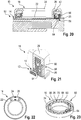
- FIG. 2 and 3 A capacitive motor vehicle operating system 10 according to a first embodiment is shown, wherein the pressure and rotary actuation device 16 is glued to a glass plate 20 of the capacitive screen 12.
- the pressure and rotary actuation device 16 comprises a stationary base 22, in particular a base ring, via which the pressure and rotary actuation device 16 is attached to the capacitive screen 12.
- the pressure and rotary actuation device 16 comprises an actuating element 24 which can be adjusted relative to the base 22, for example a rotating ring, via which the operator of the capacitive motor vehicle operating system 10 actuates the pressure and rotary actuation device 16.
- the pressure and rotary actuation device 16 comprises a plurality of magnets 28 embodied as interaction elements 26.
- a first group of magnets 28, which are assigned to the first level E1, is arranged in the rotatable actuating element 24 via a fixing ring 30 so that they can move with the rotatable actuating element 24 if this is actuated by the operator.
- a second group of magnets 28, which are assigned to the second level E2, are arranged in the area of the base 22, these magnets 28 being the interaction elements 26, since they interact with the capacitive screen 12.
- the interaction elements 26 or magnets 28 of the second group are movably arranged in an electrically conductive guide member 32, which can also be referred to as a guide ring, since the guide member 32 is ring-shaped and electrically conductive.
- the guide member 32 makes contact with at least the rotatable actuating element 24, so that an electrical connection can be established between the electrically conductive actuating element 24 and the guide member 32.
- the guide member 32 is rotated along with a rotary movement of the rotatable actuating element 24, that is to say is arranged non-rotatably in the actuating element 24.
- the pressure and rotary actuation device 16 has a stop 34, in particular a stop ring, which restricts the relative movement of the interaction elements 26 or magnets 28, i.e. the magnets 28 of the second group, in the z-direction, as will be explained below if the mode of operation of the motor vehicle operating system 10 according to the first embodiment is discussed.
- the magnet 28 assigned to the base 22, that is to say the interaction element 26, is pressed (electromagnetically) onto the user interface 14 of the capacitive screen 12, so that it contacts the user interface 14.
- the actuating element 24 or the rotating ring which is touched by the operator with his fingers, is electrically conductive, so that an electrical connection is established by the operator via the actuating element 24, the guide ring 32, the corresponding magnet 28 or the interaction element 26 to the capacitive screen 12 is. This is recognized by the capacitive screen 12.
- a rotation of the pressure and rotary actuation device 16 thus produces a relative change in position of the interaction elements 26, that is to say the magnets 28 in a plane perpendicular to the plane spanned by the capacitive screen 12, namely in the z-direction, since the user interface 14 is in the x and y directions.
- Direction is spanned.
- the other magnets 28 each with different poles face each other, whereby they attract each other.
- the relative attraction of the magnets 28 is limited by the stop 34.
- the pressure and rotary actuation device 16 is actuated by pressure, all interaction elements 26, i.e. the magnets 28, which are assigned to the base 22, are pressed simultaneously onto the user interface 14, since the actuation element 24 via the stop 34 acts on the corresponding interaction elements 26 or magnets 28 of the second group.
- the stop 34 or the stop ring can also be referred to as a pressure ring, since it ensures the pressure function of the pressure and rotary actuation device 16 by transmitting the pressure force to the interaction elements 26.
- the electrically conductive actuation element 24 that is to say the rotary ring, to touch the operating surface 14 with its periphery, which is accordingly detected by the capacitive screen 12.
- the pressure and rotary actuation device 16 includes haptic feedback, which is also generated via the magnets 28, in particular via the electromagnetic forces of the magnets 28, i.e. their mutual attraction or repulsion depending on the polarity of the opposing poles of the magnets 28 of both groups .
- the magnets 28 of the second group also have several functions at the same time, since they ensure the contact (interaction with the capacitive screen 12) as well as the haptic feedback.
- the interaction elements 26 have a stroke movement (in the z direction) of approximately 1 mm, that is to say both during the rotary actuation and the pressure actuation of the pressure and rotary actuation device 16.
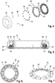
- a push and turn actuation device 16 of a capacitive motor vehicle operating system 10 according to a second embodiment is shown, which differs from the first embodiment in that the interaction elements 26 have been replaced by a single interaction element 26.
- the interaction element 26 is formed by an interaction ring 36 and comprises a plurality of sections 38 which can be actuated separately from one another, as will be explained below.
- the pressure and rotary actuation device 16 furthermore comprises a base 22 which is fastened directly to the capacitive screen 12, in particular is glued, which is not shown here for the sake of clarity.
- the pressure and rotary actuating device 16 further comprises an actuating element 24 which is adjustable or rotatable relative to the base 22 and which is electrically conductive.
- force transmission members 40 are provided in the second embodiment, each of which is spherical and interacts with the interaction element 26.
- the plurality of force transmission members 40 ensure that a movement that is as uniform as possible takes place during the rotary actuation of the pressure and rotary actuation device 16.
- At least one of the force transmission members 40 is electrically conductive, so that an electrical connection between the electrically conductive actuating element 24 and the electrically conductive interaction element 26 via the electrically conductive force transmission member 40 is ensured.
- the force transmission members 40 are rotatably coupled to the actuating element 24, which for this purpose, for example, on its internal geometry, form a receiving space for a force transmission member 40 in which the force transmission member 40 is received.
- the actuating element 24 when the actuating element 24 is actuated in a rotary manner, the force transmission members 40 are likewise rotated with the actuating element 24.
- the receiving space can be limited by stops and / or a corresponding contour can be formed on the internal geometry.
- the force transmission members 40 interact with the interaction ring 36, in particular the sections 38 of the interaction ring 36, since the force transmission members 40 move via the interaction ring 36.
- the corresponding section 38 is pressed by the corresponding force transmission member 40, viewed in the z direction, down onto the user interface 14.
- the multiple force transmission members 40 thus press the movable sections 38 of the interaction element 26 or interaction ring 36 onto the user interface 14, whereby an electrical connection from the operator via the electrically conductive actuation element 24, the electrically conductive force transmission member 40 and the corresponding one, at least in the case of the electrically conductive force transmission member 40 electrically conductive section 38 of the interaction element 26 to the user interface 14 is made.
- the sections 38 are each mechanically biased into a neutral position via a spring element 42, in which the sections 38 do not contact the user interface 14.
- the at least one interaction element 26 is mechanically preloaded.
- Tactile feedback from the pressure and rotary actuation device 16 is also provided about this, since the force transmission members 40 are pressed upward in the z-direction via the spring elements 42.
- the actuation element 24 presses all sections 38 simultaneously onto the user interface 14 via a projection 44 provided on the inside and the force transmission members 40.
- the projection 44 accordingly interacts with the interaction ring 36 or the interaction element 26.
- the user interface 14 is thus actuated with a corresponding contacting pattern, which is recognized by the capacitive screen 12 as a pressure actuation.
- the projection 44 is designed in particular in such a way that it has a stroke of 1 mm in the z-direction.
- the spring elements 42 ensure that the pressure and rotary actuation device 16 does not damage the capacitive screen 12 if too great a force should be exerted during a pressure actuation, since the spring elements 42 counteract this pressure force.
- twelve sections 38 and twelve associated spring elements 42 are shown in the embodiment shown, which can each be moved in the z direction, that is to say in a plane perpendicular to the plane spanned by the capacitive screen 12.
- FIG. 7 an alternative embodiment of the interaction ring 36 or the interaction element 26 is shown, which comprises a plurality of sections 38 which can be actuated individually and independently of one another.
- the interaction ring 36 is formed from a sheet metal that is segmented accordingly in order to provide the plurality of sections 38 which can be adjusted by the at least one force transmission member 40 relative to the user interface 14.
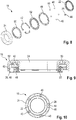
- a pressure and rotary actuation device 16 of a capacitive motor vehicle operating system 10 according to a third embodiment is shown, in which five force transmission members 40 are provided, of which one force transmission member 40 is electrically conductive.
- the electrically conductive force transmission element 40 is also assigned the electrically conductive interaction element 26 in the form of a receiving shoe 46, in which the force transmission element 40 designed as a ball is received.
- the pressure and rotary actuation device 16 comprises a base 22 which is fastened, in particular glued, to the capacitive screen 12. Furthermore, a to the base 22 adjustable or rotatable actuating element 24 is provided, which is electrically conductive and is actuated by the operator of the motor vehicle operating system 10.
- the force transmission members 40 which in turn are all designed as balls, are received in a cage 48 so that the position of the force transmission members 40 is fixed relative to one another.
- the force transmission members 40 are in turn assigned spring elements 42, via which the force transmission members 40 and thus also the at least one electrically conductive interaction element 26, that is to say the receiving shoe 46, are mechanically pretensioned.
- a toothed profile ring 50 is provided between the actuating element 24 and the spring elements 42, which ring has a toothed profile on the sides facing the spring elements 42. This can be used to provide haptic feedback when the pressure and rotary actuation device 16 is actuated.
- the spring elements 42 are also held on a spring retaining ring 52.
- the electrical connection is ensured via the electrically conductive actuating element 24, the at least one electrically conductive force transmission element 40 and the electrically conductive receiving shoe 46 or the electrically conductive interaction element 26.
- the receiving shoe 46 enlarges the contact surface on the user interface 14 accordingly.
- a pressure actuation of the pressure and rotary actuation device 16 takes place in that the actuation element 24 interacts over its entire circumference with the user interface 14, whereby a correspondingly clear signal is generated by the capacitive screen 12.
- the spring elements 42 are designed in such a way that they allow a stroke of approximately 1 mm in the z-direction when actuated by pressure until they lie flat on the spring retainer ring 52, that is, the spring path is used up.
- a fourth embodiment is shown in which five force transmission members 40 are provided in the form of balls in a manner analogous to the previous embodiment.
- the force transmission members 40 are designed to be flexible, however, so that they simultaneously provide haptic feedback, the pressure function and tolerance compensation.
- One of the force transmission members 40 is in turn designed to be electrically conductive, so that an electrical connection from the electrically conductive actuating element 24 via the electrically conductive force transmission member 40 to the user interface 14 of the capacitive screen 12 can be ensured.
- the rotary actuation results in a rotary movement of the force transmission members 40, a substantially annular rotary driver 54 transmitting the rotation of the actuating element 24 to the force transmission members 40 arranged in the cage 48.
- the cage 48 and the rotary driver 54 are formed separately from one another. Alternatively, however, these can also be coupled or even formed in one piece with one another.
- the rotary driver 54 is also designed to be electrically conductive, so that there is an electrical connection from the actuating element 24 via the rotary driver 54 to the electrically conductive force transmission element 40 or the electrically conductive interaction element 26.
- the base 22 each has recesses 56, through which at least the electrically conductive force transmission member 40 the user interface 14 can contact, so that the electrically conductive force transmission member 40 simultaneously represents the electrically conductive interaction element 26, which moves accordingly on a rotary actuation over the user interface 14 of the capacitive screen 12, which is detected by the capacitive screen 12.
- the entire actuation element 24 is pressed onto the user interface 14 of the capacitive screen 12, i.e. with its entire diameter, which is recognized by the capacitive screen 12 and converted into a corresponding pressure actuation function.
- a stroke of approximately 1 mm in the z-direction can be set via the elastic force transmission elements 40, which must be overcome when actuating the pressure.
- the elastic force transmission members 40 also set the pressure and rotary actuation device 16 back into its neutral position if there is no longer any pressure actuation.
- the base 22 can furthermore have a corresponding haptic feedback structure 55, via which tactile feedback is generated for the operator of the motor vehicle operating system 10 when he actuates the pressure and rotary actuation device 16. This is because the elastic force transmission members 40 compress due to the haptic feedback structure 55 of the base and then relax again.
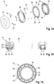
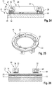
- FIG. 14 to 16 Another embodiment of the capacitive motor vehicle operating system 10 is shown, in which the at least one interaction element 26 is in turn formed by an interaction ring 36 which comprises a plurality of electrically conductive sections 38, which can each be actuated separately and independently of one another.
- the sections 38 each have a haptic feedback structure 55, which generate a tactile feedback when the pressure and rotary actuation device 16 is actuated by the operator, in particular when a rotary actuation is carried out in which the force transmission members 40 designed as balls are moved along the interaction element 26 , in particular sections 38.
- the interaction element 26 is received in the base 22, which is not electrically conductive.
- the base 22 also comprises recesses 56 through which the individual sections 38 extend.
- At least one force transmission member 40 is electrically conductive, which accordingly establishes an electrical connection between the electrically conductive actuating element 24 and the electrically conductive section 38 of the interaction element 26.
- the force transmission members 40 designed as balls or rolling bodies roll along the interaction element 26, in particular the interaction ring 36, with the sections 38 overrun by the force transmission members 40 on the capacitive screen 12 must be pressed.
- the electrically conductive force transmission element 40 then establishes the electrical connection with the correspondingly depressed section 38, which is detected by the capacitive screen 12.
- the separately actuatable sections 38 ensure that there is a relatively large actuation surface of the electrically conductive interaction element 26 on the capacitive screen 12, so that the actuation can easily be detected.
- the sections 38 include a haptic feedback structure 55, a haptic feedback results for the operator of the motor vehicle operating system 10 during the rotary actuation.
- the pressure and rotary actuation device 16 in turn comprises spring elements 42, via which the pressure actuation of the pressure and rotary actuation device 16 and the return of the pressure and rotary actuation device 16 to the neutral position are ensured.
- the spring elements 42 can be designed in such a way that a pressure actuation again results in a stroke of approximately 1 mm of the pressure and rotary actuation device 16 in the z-direction.
- the force transmission members 40 can be designed to be elastic, as a result of which damage to the capacitive screen 12 can be prevented if too great a pressure is exerted.
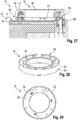
- FIG. 17 to 19 Another embodiment of a capacitive motor vehicle operating system 10 is shown, which comprises a rotary encoder 58.
- the rotary encoder 58 can generally detect the angle of rotation of the pressure and rotary actuation device 16 that occurs during a rotary actuation.
- the rotary encoder 58 has a capacitive design, since the pressure and rotary actuation device 16 has two detection areas 60, 62 which are separated from one another and are spaced apart from one another by a defined distance, such as in particular from FIG Figure 18 emerges.
- the detection areas 60, 62 are designed to be electrically conductive and accordingly form the electrically conductive interaction elements 26 which interact with the capacitive screen 12.
- the pressure and rotary actuation device 16 also has a plurality of force transmission members 40 which, when the pressure and rotary actuation device 16 is rotated, are adjusted by the adjustable actuating element 24 relative to the base 22, whereby they - depending on the angle of rotation - interact with the detection areas 60, 62 so that they establish an electrical connection to the user interface 14 via the corresponding detection area 60, 62.
- the force transmission members 40 are accordingly designed to be electrically conductive, whereby they are held in position relative to one another via a cage 48, that is to say seen in the circumferential direction.
- the cage 48 accordingly ensures that the force transmission members 40 each have the same distance from one another.
- the two detection areas 60, 62 or the two interaction elements 26 can determine at which angle and in which direction the Push and turn actuator 16 is rotated.
- the time resolution of the electrical connections of the two detection areas 60, 62 or the two interaction elements 26 is used.
- the angle of rotation can be determined accordingly via the number of actuations of the respective detection areas 60, 62.
- the pressure and rotary actuation device 16 formed separately from the capacitive screen 12 can generally also be fastened to the capacitive screen 12 via a mechanical connection such as a screw connection or the like, in particular in addition to a material connection, i.e. an adhesive bond.
- the rotary encoder 58 comprises an optical sensor 64, that is to say records the angle of rotation in an optical manner.
- the optical sensor 64 comprises at least one light transmitter and one light receiver.
- the rotary encoder 58 has a coding ring 66 which is assigned to the adjustable actuating element 24, for example, is coupled to the actuating element 24 in a rotationally fixed manner, so that the coding ring 66 is also rotated when the actuating element 24 is rotated.
- the coding ring 66 comprises a plurality of sections 68 which are separated from one another by recesses 70. A light beam emitted by the optical sensor 64 can pass through the recesses 70, which in turn is detected by the optical sensor 64.
- the light transmitter and the light receiver are assigned to opposite sides of the coding ring 66.
- the optical sensor 64 When the pressure and rotary actuation device 16 is actuated in a rotary manner, the optical sensor 64 accordingly detects the optical changes occurring due to the coding ring 66 in order to deduce the corresponding angle of rotation during the rotary actuation.
- the optical changes are caused by the fact that the light from the transmitter of the optical sensor 64 passes through one of the recesses 70 and can be received by the receiver of the optical sensor 64 or is blocked by one of the sections 68.
- the optical sensor 64 works with two light beams, for example with two light transmitters and two light receivers, the direction of rotation can also be used can be recognized when the pressure and rotary actuation device 16 is rotated.
- the optical sensor 64 is assigned to the glass plate 20 of the capacitive screen 12, in particular partially accommodated in the glass plate 20.
- the glass plate 20 is at least partially drilled through.
- the pressure actuation of the pressure and rotary actuation device 16 takes place in a known manner in that spring elements 42 are pressed together until the electrically conductive actuation element 24 comes into contact with the capacitive screen 12, in particular the user interface 14, which is accordingly detected by the capacitive screen 12.
- the actuation element 24 represents the interaction element 26, which interacts with the capacitive screen 12.
- the spring elements 42 provide the haptic feedback and also ensure that the actuating element 24 returns to its neutral position.
- the rotary encoder 58 comprises at least one Hall sensor 72 which interacts with magnets 28 which are assigned to the actuating element 24.
- the magnets 28 can be arranged in a guide member 32, which can also be referred to as a guide ring.
- the guide member 32 can in turn be coupled in a rotationally fixed manner to the actuation element 24, so that the magnets 28 move over the user interface 14 when actuated in a rotary manner, and thus also over the Hall sensors 72.
- the magnets 28 When the push-and-turn actuator 16 is rotated, the magnets 28 cause a change in magnetic flux, which is detected by the Hall sensor 72.
- magnets 28 are assigned to user interface 14, in particular with alternating polarity.
- the Hall sensors 72 can be arranged below the glass plate 20 of the capacitive screen 12, for example below the capacitive sensor layer of the capacitive screen 12.
- the magnets 28 can represent the interaction elements 26, as was previously based on FIG Figures 2 and 3 has already been explained.
- the actuation element 24 can represent the interaction element 26, provided that a pressure actuation is exerted, as has already been described above.
- the spring elements 42 can in turn serve for haptic feedback and provide a stroke in the z-direction of approximately 1 mm.
- the rotary encoder 58 comprises at least one inductive coil 74, which is formed, for example, via an FPC cable.
- the FPC cable is also arranged below the glass plate 20 of the capacitive screen 12, with a change in inductance being detected by the at least one inductive coil 74 in order to detect a rotation of the push-and-turn actuator 16.
- an induction material 76 such as a piece of iron is assigned to the actuating element 24, which is correspondingly detected by the at least one inductive coil 74 when the actuating element 24 is rotated, that is to say is subjected to a rotary actuation.
- the pressure actuation can again take place against the spring force of the spring elements 42, so that the actuation element 24 serves as the interaction element 26, since the electrically conductive actuation element 24 interacts with the capacitive screen 12.
Landscapes
- Engineering & Computer Science (AREA)
- General Engineering & Computer Science (AREA)
- Theoretical Computer Science (AREA)
- Physics & Mathematics (AREA)
- General Physics & Mathematics (AREA)
- Human Computer Interaction (AREA)
- Mechanical Engineering (AREA)
- Chemical & Material Sciences (AREA)
- Combustion & Propulsion (AREA)
- Transportation (AREA)
- Mechanical Control Devices (AREA)
- Switches With Compound Operations (AREA)
- Position Input By Displaying (AREA)
- User Interface Of Digital Computer (AREA)
Applications Claiming Priority (1)
| Application Number | Priority Date | Filing Date | Title |
|---|---|---|---|
| DE102018116833.0A DE102018116833A1 (de) | 2018-07-11 | 2018-07-11 | Kapazitives Kraftfahrzeugbediensystem |
Publications (2)
| Publication Number | Publication Date |
|---|---|
| EP3594044A1 EP3594044A1 (de) | 2020-01-15 |
| EP3594044B1 true EP3594044B1 (de) | 2021-09-01 |
Family
ID=67180688
Family Applications (1)
| Application Number | Title | Priority Date | Filing Date |
|---|---|---|---|
| EP19184508.0A Revoked EP3594044B1 (de) | 2018-07-11 | 2019-07-04 | Kapazitives kraftfahrzeugbediensystem |
Country Status (5)
| Country | Link |
|---|---|
| US (1) | US11467696B2 (zh) |
| EP (1) | EP3594044B1 (zh) |
| JP (1) | JP2020038625A (zh) |
| CN (1) | CN110716638A (zh) |
| DE (1) | DE102018116833A1 (zh) |
Cited By (1)
| Publication number | Priority date | Publication date | Assignee | Title |
|---|---|---|---|---|
| DE102022201010A1 (de) | 2022-01-31 | 2023-08-03 | Elektrobit Automotive Gmbh | Bedieneinheit aufweisend eine elektrooptische Anzeigevorrichtung und eine haptische Eingabevorrichtung mit einer Handhabe |
Families Citing this family (10)
| Publication number | Priority date | Publication date | Assignee | Title |
|---|---|---|---|---|
| DE102018120575A1 (de) * | 2018-07-12 | 2020-01-16 | Preh Gmbh | Eingabevorrichtung mit beweglicher Handhabe auf kapazitiver Detektionsfläche und kapazitiven Koppeleinrichtungen |
| JP7219615B2 (ja) * | 2018-12-28 | 2023-02-08 | 株式会社ジャパンディスプレイ | 操作支援装置 |
| US11188161B2 (en) | 2019-08-20 | 2021-11-30 | Synaptics Incorporated | Automative knob sensing device |
| WO2021079694A1 (ja) * | 2019-10-23 | 2021-04-29 | アルプスアルパイン株式会社 | 複合操作型入力装置 |
| JP6804697B1 (ja) * | 2019-12-26 | 2020-12-23 | 三菱電機株式会社 | 触覚提示制御装置、触覚提示パネル、触覚提示タッチパネル、および触覚提示タッチディスプレイ |
| WO2021140550A1 (ja) * | 2020-01-07 | 2021-07-15 | 三菱電機株式会社 | 触覚提示パネル、触覚提示タッチパネル、触覚提示タッチディスプレイ |
| CN111267129B (zh) * | 2020-02-24 | 2022-07-29 | 东南大学 | 陪护机器人的控制装置 |
| JP7349949B2 (ja) * | 2020-03-30 | 2023-09-25 | 株式会社ユーシン | 操作つまみ装置 |
| DE102022122461A1 (de) | 2022-09-05 | 2024-03-07 | Uedelhoven GmbH & CO. KG | Bedienvorrichtung zum Anbringen auf einem Bildschirm |
| US20240105404A1 (en) * | 2022-09-27 | 2024-03-28 | Cypress Semiconductor Corporation | Detecting push button press of a passive rotary knob on a touch screen |
Citations (10)
| Publication number | Priority date | Publication date | Assignee | Title |
|---|---|---|---|---|
| DE102006043208A1 (de) | 2006-09-11 | 2008-03-27 | Siemens Ag | Touchpad oder -screen und Stellelement für Touchpad oder -screen |
| WO2014093830A1 (en) | 2012-12-14 | 2014-06-19 | Panasonic Automotive Systems Company Of America, Division Of Panasonic Corporation Of North America | Capacitive rotary encoder |
| DE102013014792A1 (de) | 2013-09-09 | 2015-03-12 | Leopold Kostal Gmbh & Co. Kg | Bildschirmbasiertes Fahrzeugbediensystem |
| DE102015002300A1 (de) * | 2015-02-24 | 2016-08-25 | GM Global Technology Operations LLC (n. d. Ges. d. Staates Delaware) | Eingabevorrichtung für eine berührungssensitive Eingabeoberfläche |
| DE102015210657A1 (de) | 2015-06-11 | 2016-12-15 | Volkswagen Aktiengesellschaft | Verfahren zur Erkennung einer Stellbewegung eines auf einer Anzeigefläche befindlichen Stellelementes in einem Kraftfahrzeug und Vorrichtung zur Durchführung des Verfahrens |
| DE102015117226A1 (de) | 2015-09-15 | 2017-03-16 | Preh Gmbh | Anordnung aus elektrischer Anzeige und Drehsteller mit Fremdkörpereindringschutz |
| DE102015118587A1 (de) | 2015-10-30 | 2017-05-04 | Preh Gmbh | Bedienanordnung aus Betätigungsteil mit Eingabefläche und auf der Eingabefläche angeordnetem Drehsteller |
| EP3220402A1 (en) | 2014-11-10 | 2017-09-20 | Panasonic Intellectual Property Management Co., Ltd. | Input device |
| DE102016120638A1 (de) | 2016-10-28 | 2018-05-03 | Preh Gmbh | Eingabegerät mit Betätigungsteil und magnetischem Messfeld zur Ermittlung eines Positionsparameters des Betätigungsteils |
| EP3822753A1 (de) | 2017-01-25 | 2021-05-19 | Behr-Hella Thermocontrol GmbH | Bedienvorrichtung für ein kraftfahrzeug |
Family Cites Families (11)
| Publication number | Priority date | Publication date | Assignee | Title |
|---|---|---|---|---|
| US8199114B1 (en) * | 2000-09-26 | 2012-06-12 | Denny Jaeger | Touch sensor control devices |
| DE102012018291B4 (de) * | 2012-09-14 | 2016-05-04 | Audi Ag | Bedienvorrichtung für eine Funktionseinrichtung eines Kraftfahrzeugs |
| EP3112996A1 (de) * | 2015-06-30 | 2017-01-04 | Siemens Aktiengesellschaft | Bedienelement und bedien- und beobachtungssystem |
| FR3035981A1 (fr) * | 2015-09-17 | 2016-11-11 | Continental Automotive France | Commutateur rotatif agence sur un ecran |
| JP6500936B2 (ja) * | 2016-07-20 | 2019-04-17 | 株式会社デンソー | 操作装置 |
| US10409470B2 (en) * | 2016-09-14 | 2019-09-10 | Microsoft Technology Licensing, Llc | Touch-display accessory with relayed display plane |
| FR3058938B1 (fr) * | 2016-09-28 | 2019-08-16 | Dav | Interface pour vehicule automobile et procede d'interfacage |
| FR3056475B1 (fr) * | 2016-09-28 | 2018-11-30 | Dav | Interface pour vehicule automobile |
| FR3056474B1 (fr) * | 2016-09-28 | 2018-12-07 | Dav | Interface pour vehicule automobile |
| CN108146345B (zh) * | 2016-12-06 | 2021-03-30 | Lg电子株式会社 | 车辆控制装置及包括该车辆控制装置的车辆 |
| JP6342105B1 (ja) * | 2017-12-14 | 2018-06-13 | 三菱電機株式会社 | 操作支援装置、タッチパネル装置、及びタッチパネル入力システム |
-
2018
- 2018-07-11 DE DE102018116833.0A patent/DE102018116833A1/de active Pending
-
2019
- 2019-07-04 EP EP19184508.0A patent/EP3594044B1/de not_active Revoked
- 2019-07-10 US US16/507,233 patent/US11467696B2/en active Active
- 2019-07-10 JP JP2019128252A patent/JP2020038625A/ja active Pending
- 2019-07-10 CN CN201910620299.3A patent/CN110716638A/zh active Pending
Patent Citations (10)
| Publication number | Priority date | Publication date | Assignee | Title |
|---|---|---|---|---|
| DE102006043208A1 (de) | 2006-09-11 | 2008-03-27 | Siemens Ag | Touchpad oder -screen und Stellelement für Touchpad oder -screen |
| WO2014093830A1 (en) | 2012-12-14 | 2014-06-19 | Panasonic Automotive Systems Company Of America, Division Of Panasonic Corporation Of North America | Capacitive rotary encoder |
| DE102013014792A1 (de) | 2013-09-09 | 2015-03-12 | Leopold Kostal Gmbh & Co. Kg | Bildschirmbasiertes Fahrzeugbediensystem |
| EP3220402A1 (en) | 2014-11-10 | 2017-09-20 | Panasonic Intellectual Property Management Co., Ltd. | Input device |
| DE102015002300A1 (de) * | 2015-02-24 | 2016-08-25 | GM Global Technology Operations LLC (n. d. Ges. d. Staates Delaware) | Eingabevorrichtung für eine berührungssensitive Eingabeoberfläche |
| DE102015210657A1 (de) | 2015-06-11 | 2016-12-15 | Volkswagen Aktiengesellschaft | Verfahren zur Erkennung einer Stellbewegung eines auf einer Anzeigefläche befindlichen Stellelementes in einem Kraftfahrzeug und Vorrichtung zur Durchführung des Verfahrens |
| DE102015117226A1 (de) | 2015-09-15 | 2017-03-16 | Preh Gmbh | Anordnung aus elektrischer Anzeige und Drehsteller mit Fremdkörpereindringschutz |
| DE102015118587A1 (de) | 2015-10-30 | 2017-05-04 | Preh Gmbh | Bedienanordnung aus Betätigungsteil mit Eingabefläche und auf der Eingabefläche angeordnetem Drehsteller |
| DE102016120638A1 (de) | 2016-10-28 | 2018-05-03 | Preh Gmbh | Eingabegerät mit Betätigungsteil und magnetischem Messfeld zur Ermittlung eines Positionsparameters des Betätigungsteils |
| EP3822753A1 (de) | 2017-01-25 | 2021-05-19 | Behr-Hella Thermocontrol GmbH | Bedienvorrichtung für ein kraftfahrzeug |
Cited By (1)
| Publication number | Priority date | Publication date | Assignee | Title |
|---|---|---|---|---|
| DE102022201010A1 (de) | 2022-01-31 | 2023-08-03 | Elektrobit Automotive Gmbh | Bedieneinheit aufweisend eine elektrooptische Anzeigevorrichtung und eine haptische Eingabevorrichtung mit einer Handhabe |
Also Published As
| Publication number | Publication date |
|---|---|
| CN110716638A (zh) | 2020-01-21 |
| JP2020038625A (ja) | 2020-03-12 |
| EP3594044A1 (de) | 2020-01-15 |
| US11467696B2 (en) | 2022-10-11 |
| DE102018116833A1 (de) | 2020-01-16 |
| US20200019263A1 (en) | 2020-01-16 |
Similar Documents
| Publication | Publication Date | Title |
|---|---|---|
| EP3594044B1 (de) | Kapazitives kraftfahrzeugbediensystem | |
| EP2867739B1 (de) | Multifunktions-bedienvorrichtung, insbesondere für eine kfz-komponente | |
| DE102011083524B4 (de) | Dreh-/Drück-Bedienvorrichtung für ein Mensch-Maschine-Interface | |
| EP2920665B1 (de) | Bedienvorrichtung für eine fahrzeugkomponente | |
| EP2984667B1 (de) | Vorrichtung zur bedienung mehrerer funktionen in einem kraftfahrzeug | |
| EP2945832B1 (de) | Lenkrad mit optischem fingernavigationsmodul | |
| EP3074836B1 (de) | Stellglied, insbesondere für ein kraftfahrzeug | |
| WO2015086589A1 (de) | Bedienvorrichtung für ein elektrisches gerät oder eine elektrische anlage, insbesondere für eine fahrzeugkomponente | |
| WO2013060501A1 (de) | Bedienelement mit magnetischer rückstellung | |
| DE102015008517A1 (de) | Stellglied, insbesondere für ein Kraftfahrzeug | |
| EP3309967B1 (de) | Kapazitive schalt-vorrichtung | |
| EP2647126B1 (de) | Bedieneinheit mit kapazitivem berührungssensor | |
| EP3355474B1 (de) | Schalt-vorrichtung zur umwandlung einer manuellen und/oder mechanischen bewegung in ein schaltsignal | |
| DE102019115950A1 (de) | Drehsteller mit Drückfunktion durch verbesserte Drehlagerung | |
| DE102021208150A1 (de) | Bedienvorrichtung und Bedienoberfläche für ein Fahrzeug | |
| DE102011055319B4 (de) | Bedienvorrichtung eines Multifunktionssystems für Kraftfahrzeuge | |
| DE102018120561B4 (de) | Multifunktionales Bedienelement für ein Kraftfahrzeug | |
| DE102015003204A1 (de) | Bedienvorrichtung für ein Kraftfahrzeug, Kraftfahrzeug sowie Verfahren | |
| DE102018010324B4 (de) | Multifunktionales Bedienelement für ein Kraftfahrzeug | |
| EP3152837B1 (de) | Vorrichtung zur bedienung mehrerer funktionen in einem kraftfahrzeug | |
| WO1990003013A1 (de) | Xy-richtungseingabevorrichtung und verfahren zur bildung von bewegungsangaben | |
| DE102018010327A1 (de) | Multifunktionales Bedienelement für ein Kraftfahrzeug | |
| DE102018010325A1 (de) | Multifunktionales Bedienelement für ein Kraftfahrzeug | |
| DE102018010328A1 (de) | Multifunktionales Bedienelement für ein Kraftfahrzeug | |
| DE102020100332A1 (de) | Kapazitives Kraftfahrzeugbediensystem |
Legal Events
| Date | Code | Title | Description |
|---|---|---|---|
| PUAI | Public reference made under article 153(3) epc to a published international application that has entered the european phase |
Free format text: ORIGINAL CODE: 0009012 |
|
| STAA | Information on the status of an ep patent application or granted ep patent |
Free format text: STATUS: THE APPLICATION HAS BEEN PUBLISHED |
|
| AK | Designated contracting states |
Kind code of ref document: A1 Designated state(s): AL AT BE BG CH CY CZ DE DK EE ES FI FR GB GR HR HU IE IS IT LI LT LU LV MC MK MT NL NO PL PT RO RS SE SI SK SM TR |
|
| AX | Request for extension of the european patent |
Extension state: BA ME |
|
| STAA | Information on the status of an ep patent application or granted ep patent |
Free format text: STATUS: REQUEST FOR EXAMINATION WAS MADE |
|
| 17P | Request for examination filed |
Effective date: 20200512 |
|
| RBV | Designated contracting states (corrected) |
Designated state(s): AL AT BE BG CH CY CZ DE DK EE ES FI FR GB GR HR HU IE IS IT LI LT LU LV MC MK MT NL NO PL PT RO RS SE SI SK SM TR |
|
| STAA | Information on the status of an ep patent application or granted ep patent |
Free format text: STATUS: EXAMINATION IS IN PROGRESS |
|
| REG | Reference to a national code |
Ref country code: DE Ref legal event code: R079 Ref document number: 502019002177 Country of ref document: DE Free format text: PREVIOUS MAIN CLASS: B60K0037060000 Ipc: G06F0003044000 |
|
| 17Q | First examination report despatched |
Effective date: 20210209 |
|
| GRAP | Despatch of communication of intention to grant a patent |
Free format text: ORIGINAL CODE: EPIDOSNIGR1 |
|
| STAA | Information on the status of an ep patent application or granted ep patent |
Free format text: STATUS: GRANT OF PATENT IS INTENDED |
|
| RIC1 | Information provided on ipc code assigned before grant |
Ipc: H03K 17/96 20060101ALI20210224BHEP Ipc: G06F 3/0362 20130101ALI20210224BHEP Ipc: G06F 3/044 20060101AFI20210224BHEP Ipc: B60K 37/06 20060101ALI20210224BHEP |
|
| INTG | Intention to grant announced |
Effective date: 20210329 |
|
| GRAS | Grant fee paid |
Free format text: ORIGINAL CODE: EPIDOSNIGR3 |
|
| GRAA | (expected) grant |
Free format text: ORIGINAL CODE: 0009210 |
|
| STAA | Information on the status of an ep patent application or granted ep patent |
Free format text: STATUS: THE PATENT HAS BEEN GRANTED |
|
| AK | Designated contracting states |
Kind code of ref document: B1 Designated state(s): AL AT BE BG CH CY CZ DE DK EE ES FI FR GB GR HR HU IE IS IT LI LT LU LV MC MK MT NL NO PL PT RO RS SE SI SK SM TR |
|
| REG | Reference to a national code |
Ref country code: GB Ref legal event code: FG4D Free format text: NOT ENGLISH |
|
| REG | Reference to a national code |
Ref country code: CH Ref legal event code: EP Ref country code: AT Ref legal event code: REF Ref document number: 1426914 Country of ref document: AT Kind code of ref document: T Effective date: 20210915 |
|
| REG | Reference to a national code |
Ref country code: DE Ref legal event code: R096 Ref document number: 502019002177 Country of ref document: DE |
|
| REG | Reference to a national code |
Ref country code: IE Ref legal event code: FG4D Free format text: LANGUAGE OF EP DOCUMENT: GERMAN |
|
| REG | Reference to a national code |
Ref country code: LT Ref legal event code: MG9D |
|
| REG | Reference to a national code |
Ref country code: NL Ref legal event code: MP Effective date: 20210901 |
|
| PG25 | Lapsed in a contracting state [announced via postgrant information from national office to epo] |
Ref country code: BG Free format text: LAPSE BECAUSE OF FAILURE TO SUBMIT A TRANSLATION OF THE DESCRIPTION OR TO PAY THE FEE WITHIN THE PRESCRIBED TIME-LIMIT Effective date: 20211201 Ref country code: LT Free format text: LAPSE BECAUSE OF FAILURE TO SUBMIT A TRANSLATION OF THE DESCRIPTION OR TO PAY THE FEE WITHIN THE PRESCRIBED TIME-LIMIT Effective date: 20210901 Ref country code: HR Free format text: LAPSE BECAUSE OF FAILURE TO SUBMIT A TRANSLATION OF THE DESCRIPTION OR TO PAY THE FEE WITHIN THE PRESCRIBED TIME-LIMIT Effective date: 20210901 Ref country code: NO Free format text: LAPSE BECAUSE OF FAILURE TO SUBMIT A TRANSLATION OF THE DESCRIPTION OR TO PAY THE FEE WITHIN THE PRESCRIBED TIME-LIMIT Effective date: 20211201 Ref country code: SE Free format text: LAPSE BECAUSE OF FAILURE TO SUBMIT A TRANSLATION OF THE DESCRIPTION OR TO PAY THE FEE WITHIN THE PRESCRIBED TIME-LIMIT Effective date: 20210901 Ref country code: RS Free format text: LAPSE BECAUSE OF FAILURE TO SUBMIT A TRANSLATION OF THE DESCRIPTION OR TO PAY THE FEE WITHIN THE PRESCRIBED TIME-LIMIT Effective date: 20210901 Ref country code: FI Free format text: LAPSE BECAUSE OF FAILURE TO SUBMIT A TRANSLATION OF THE DESCRIPTION OR TO PAY THE FEE WITHIN THE PRESCRIBED TIME-LIMIT Effective date: 20210901 Ref country code: ES Free format text: LAPSE BECAUSE OF FAILURE TO SUBMIT A TRANSLATION OF THE DESCRIPTION OR TO PAY THE FEE WITHIN THE PRESCRIBED TIME-LIMIT Effective date: 20210901 |
|
| PG25 | Lapsed in a contracting state [announced via postgrant information from national office to epo] |
Ref country code: PL Free format text: LAPSE BECAUSE OF FAILURE TO SUBMIT A TRANSLATION OF THE DESCRIPTION OR TO PAY THE FEE WITHIN THE PRESCRIBED TIME-LIMIT Effective date: 20210901 Ref country code: LV Free format text: LAPSE BECAUSE OF FAILURE TO SUBMIT A TRANSLATION OF THE DESCRIPTION OR TO PAY THE FEE WITHIN THE PRESCRIBED TIME-LIMIT Effective date: 20210901 Ref country code: GR Free format text: LAPSE BECAUSE OF FAILURE TO SUBMIT A TRANSLATION OF THE DESCRIPTION OR TO PAY THE FEE WITHIN THE PRESCRIBED TIME-LIMIT Effective date: 20211202 |
|
| PG25 | Lapsed in a contracting state [announced via postgrant information from national office to epo] |
Ref country code: IS Free format text: LAPSE BECAUSE OF FAILURE TO SUBMIT A TRANSLATION OF THE DESCRIPTION OR TO PAY THE FEE WITHIN THE PRESCRIBED TIME-LIMIT Effective date: 20220101 Ref country code: SM Free format text: LAPSE BECAUSE OF FAILURE TO SUBMIT A TRANSLATION OF THE DESCRIPTION OR TO PAY THE FEE WITHIN THE PRESCRIBED TIME-LIMIT Effective date: 20210901 Ref country code: SK Free format text: LAPSE BECAUSE OF FAILURE TO SUBMIT A TRANSLATION OF THE DESCRIPTION OR TO PAY THE FEE WITHIN THE PRESCRIBED TIME-LIMIT Effective date: 20210901 Ref country code: RO Free format text: LAPSE BECAUSE OF FAILURE TO SUBMIT A TRANSLATION OF THE DESCRIPTION OR TO PAY THE FEE WITHIN THE PRESCRIBED TIME-LIMIT Effective date: 20210901 Ref country code: PT Free format text: LAPSE BECAUSE OF FAILURE TO SUBMIT A TRANSLATION OF THE DESCRIPTION OR TO PAY THE FEE WITHIN THE PRESCRIBED TIME-LIMIT Effective date: 20220103 Ref country code: NL Free format text: LAPSE BECAUSE OF FAILURE TO SUBMIT A TRANSLATION OF THE DESCRIPTION OR TO PAY THE FEE WITHIN THE PRESCRIBED TIME-LIMIT Effective date: 20210901 Ref country code: EE Free format text: LAPSE BECAUSE OF FAILURE TO SUBMIT A TRANSLATION OF THE DESCRIPTION OR TO PAY THE FEE WITHIN THE PRESCRIBED TIME-LIMIT Effective date: 20210901 Ref country code: CZ Free format text: LAPSE BECAUSE OF FAILURE TO SUBMIT A TRANSLATION OF THE DESCRIPTION OR TO PAY THE FEE WITHIN THE PRESCRIBED TIME-LIMIT Effective date: 20210901 Ref country code: AL Free format text: LAPSE BECAUSE OF FAILURE TO SUBMIT A TRANSLATION OF THE DESCRIPTION OR TO PAY THE FEE WITHIN THE PRESCRIBED TIME-LIMIT Effective date: 20210901 |
|
| REG | Reference to a national code |
Ref country code: DE Ref legal event code: R026 Ref document number: 502019002177 Country of ref document: DE |
|
| PLBI | Opposition filed |
Free format text: ORIGINAL CODE: 0009260 |
|
| PLAX | Notice of opposition and request to file observation + time limit sent |
Free format text: ORIGINAL CODE: EPIDOSNOBS2 |
|
| 26 | Opposition filed |
Opponent name: PREH GMBH Effective date: 20220601 |
|
| PG25 | Lapsed in a contracting state [announced via postgrant information from national office to epo] |
Ref country code: IT Free format text: LAPSE BECAUSE OF FAILURE TO SUBMIT A TRANSLATION OF THE DESCRIPTION OR TO PAY THE FEE WITHIN THE PRESCRIBED TIME-LIMIT Effective date: 20210901 Ref country code: DK Free format text: LAPSE BECAUSE OF FAILURE TO SUBMIT A TRANSLATION OF THE DESCRIPTION OR TO PAY THE FEE WITHIN THE PRESCRIBED TIME-LIMIT Effective date: 20210901 |
|
| PG25 | Lapsed in a contracting state [announced via postgrant information from national office to epo] |
Ref country code: SI Free format text: LAPSE BECAUSE OF FAILURE TO SUBMIT A TRANSLATION OF THE DESCRIPTION OR TO PAY THE FEE WITHIN THE PRESCRIBED TIME-LIMIT Effective date: 20210901 |
|
| PLBB | Reply of patent proprietor to notice(s) of opposition received |
Free format text: ORIGINAL CODE: EPIDOSNOBS3 |
|
| PG25 | Lapsed in a contracting state [announced via postgrant information from national office to epo] |
Ref country code: MC Free format text: LAPSE BECAUSE OF FAILURE TO SUBMIT A TRANSLATION OF THE DESCRIPTION OR TO PAY THE FEE WITHIN THE PRESCRIBED TIME-LIMIT Effective date: 20210901 |
|
| REG | Reference to a national code |
Ref country code: CH Ref legal event code: PL |
|
| REG | Reference to a national code |
Ref country code: BE Ref legal event code: MM Effective date: 20220731 |
|
| PG25 | Lapsed in a contracting state [announced via postgrant information from national office to epo] |
Ref country code: LU Free format text: LAPSE BECAUSE OF NON-PAYMENT OF DUE FEES Effective date: 20220704 Ref country code: LI Free format text: LAPSE BECAUSE OF NON-PAYMENT OF DUE FEES Effective date: 20220731 Ref country code: CH Free format text: LAPSE BECAUSE OF NON-PAYMENT OF DUE FEES Effective date: 20220731 |
|
| PG25 | Lapsed in a contracting state [announced via postgrant information from national office to epo] |
Ref country code: BE Free format text: LAPSE BECAUSE OF NON-PAYMENT OF DUE FEES Effective date: 20220731 |
|
| PG25 | Lapsed in a contracting state [announced via postgrant information from national office to epo] |
Ref country code: IE Free format text: LAPSE BECAUSE OF NON-PAYMENT OF DUE FEES Effective date: 20220704 |
|
| PGFP | Annual fee paid to national office [announced via postgrant information from national office to epo] |
Ref country code: FR Payment date: 20230726 Year of fee payment: 5 Ref country code: DE Payment date: 20230725 Year of fee payment: 5 |
|
| GBPC | Gb: european patent ceased through non-payment of renewal fee |
Effective date: 20230704 |
|
| PG25 | Lapsed in a contracting state [announced via postgrant information from national office to epo] |
Ref country code: HU Free format text: LAPSE BECAUSE OF FAILURE TO SUBMIT A TRANSLATION OF THE DESCRIPTION OR TO PAY THE FEE WITHIN THE PRESCRIBED TIME-LIMIT; INVALID AB INITIO Effective date: 20190704 |
|
| PG25 | Lapsed in a contracting state [announced via postgrant information from national office to epo] |
Ref country code: MK Free format text: LAPSE BECAUSE OF FAILURE TO SUBMIT A TRANSLATION OF THE DESCRIPTION OR TO PAY THE FEE WITHIN THE PRESCRIBED TIME-LIMIT Effective date: 20210901 Ref country code: CY Free format text: LAPSE BECAUSE OF FAILURE TO SUBMIT A TRANSLATION OF THE DESCRIPTION OR TO PAY THE FEE WITHIN THE PRESCRIBED TIME-LIMIT Effective date: 20210901 Ref country code: GB Free format text: LAPSE BECAUSE OF NON-PAYMENT OF DUE FEES Effective date: 20230704 |
|
| RDAF | Communication despatched that patent is revoked |
Free format text: ORIGINAL CODE: EPIDOSNREV1 |
|
| PLAB | Opposition data, opponent's data or that of the opponent's representative modified |
Free format text: ORIGINAL CODE: 0009299OPPO |
|
| PG25 | Lapsed in a contracting state [announced via postgrant information from national office to epo] |
Ref country code: TR Free format text: LAPSE BECAUSE OF FAILURE TO SUBMIT A TRANSLATION OF THE DESCRIPTION OR TO PAY THE FEE WITHIN THE PRESCRIBED TIME-LIMIT Effective date: 20210901 |
|
| R26 | Opposition filed (corrected) |
Opponent name: PREH GMBH Effective date: 20220601 |
|
| APAH | Appeal reference modified |
Free format text: ORIGINAL CODE: EPIDOSCREFNO |
|
| APAW | Appeal reference deleted |
Free format text: ORIGINAL CODE: EPIDOSDREFNO |
|
| APBP | Date of receipt of notice of appeal recorded |
Free format text: ORIGINAL CODE: EPIDOSNNOA2O |
|
| APBU | Appeal procedure closed |
Free format text: ORIGINAL CODE: EPIDOSNNOA9O |
|
| REG | Reference to a national code |
Ref country code: DE Ref legal event code: R103 Ref document number: 502019002177 Country of ref document: DE Ref country code: DE Ref legal event code: R064 Ref document number: 502019002177 Country of ref document: DE |
|
| RDAG | Patent revoked |
Free format text: ORIGINAL CODE: 0009271 |
|
| STAA | Information on the status of an ep patent application or granted ep patent |
Free format text: STATUS: PATENT REVOKED |
|
| REG | Reference to a national code |
Ref country code: CH Ref legal event code: PL |
|
| 27W | Patent revoked |
Effective date: 20240807 |