EP3593898A1 - Producing fertilizer granules with a defined size distribution - Google Patents
Producing fertilizer granules with a defined size distribution Download PDFInfo
- Publication number
- EP3593898A1 EP3593898A1 EP18183433.4A EP18183433A EP3593898A1 EP 3593898 A1 EP3593898 A1 EP 3593898A1 EP 18183433 A EP18183433 A EP 18183433A EP 3593898 A1 EP3593898 A1 EP 3593898A1
- Authority
- EP
- European Patent Office
- Prior art keywords
- fluid
- particles
- bed granulator
- size
- splitter
- Prior art date
- Legal status (The legal status is an assumption and is not a legal conclusion. Google has not performed a legal analysis and makes no representation as to the accuracy of the status listed.)
- Granted
Links
Images




Classifications
-
- B—PERFORMING OPERATIONS; TRANSPORTING
- B01—PHYSICAL OR CHEMICAL PROCESSES OR APPARATUS IN GENERAL
- B01J—CHEMICAL OR PHYSICAL PROCESSES, e.g. CATALYSIS OR COLLOID CHEMISTRY; THEIR RELEVANT APPARATUS
- B01J2/00—Processes or devices for granulating materials, e.g. fertilisers in general; Rendering particulate materials free flowing in general, e.g. making them hydrophobic
-
- B—PERFORMING OPERATIONS; TRANSPORTING
- B01—PHYSICAL OR CHEMICAL PROCESSES OR APPARATUS IN GENERAL
- B01J—CHEMICAL OR PHYSICAL PROCESSES, e.g. CATALYSIS OR COLLOID CHEMISTRY; THEIR RELEVANT APPARATUS
- B01J2/00—Processes or devices for granulating materials, e.g. fertilisers in general; Rendering particulate materials free flowing in general, e.g. making them hydrophobic
- B01J2/16—Processes or devices for granulating materials, e.g. fertilisers in general; Rendering particulate materials free flowing in general, e.g. making them hydrophobic by suspending the powder material in a gas, e.g. in fluidised beds or as a falling curtain
-
- B—PERFORMING OPERATIONS; TRANSPORTING
- B01—PHYSICAL OR CHEMICAL PROCESSES OR APPARATUS IN GENERAL
- B01J—CHEMICAL OR PHYSICAL PROCESSES, e.g. CATALYSIS OR COLLOID CHEMISTRY; THEIR RELEVANT APPARATUS
- B01J8/00—Chemical or physical processes in general, conducted in the presence of fluids and solid particles; Apparatus for such processes
- B01J8/0015—Feeding of the particles in the reactor; Evacuation of the particles out of the reactor
-
- B—PERFORMING OPERATIONS; TRANSPORTING
- B01—PHYSICAL OR CHEMICAL PROCESSES OR APPARATUS IN GENERAL
- B01J—CHEMICAL OR PHYSICAL PROCESSES, e.g. CATALYSIS OR COLLOID CHEMISTRY; THEIR RELEVANT APPARATUS
- B01J8/00—Chemical or physical processes in general, conducted in the presence of fluids and solid particles; Apparatus for such processes
- B01J8/18—Chemical or physical processes in general, conducted in the presence of fluids and solid particles; Apparatus for such processes with fluidised particles
- B01J8/1809—Controlling processes
-
- B—PERFORMING OPERATIONS; TRANSPORTING
- B01—PHYSICAL OR CHEMICAL PROCESSES OR APPARATUS IN GENERAL
- B01J—CHEMICAL OR PHYSICAL PROCESSES, e.g. CATALYSIS OR COLLOID CHEMISTRY; THEIR RELEVANT APPARATUS
- B01J8/00—Chemical or physical processes in general, conducted in the presence of fluids and solid particles; Apparatus for such processes
- B01J8/18—Chemical or physical processes in general, conducted in the presence of fluids and solid particles; Apparatus for such processes with fluidised particles
- B01J8/1872—Details of the fluidised bed reactor
-
- C—CHEMISTRY; METALLURGY
- C05—FERTILISERS; MANUFACTURE THEREOF
- C05C—NITROGENOUS FERTILISERS
- C05C9/00—Fertilisers containing urea or urea compounds
- C05C9/005—Post-treatment
-
- C—CHEMISTRY; METALLURGY
- C05—FERTILISERS; MANUFACTURE THEREOF
- C05G—MIXTURES OF FERTILISERS COVERED INDIVIDUALLY BY DIFFERENT SUBCLASSES OF CLASS C05; MIXTURES OF ONE OR MORE FERTILISERS WITH MATERIALS NOT HAVING A SPECIFIC FERTILISING ACTIVITY, e.g. PESTICIDES, SOIL-CONDITIONERS, WETTING AGENTS; FERTILISERS CHARACTERISED BY THEIR FORM
- C05G5/00—Fertilisers characterised by their form
- C05G5/10—Solid or semi-solid fertilisers, e.g. powders
- C05G5/12—Granules or flakes
Definitions
- the invention relates to a fluid-bed granulator system for producing fertilizer granules with a defined size, a process for a particle size controlled granulation of urea containing particles, a urea granulation plant and the use of the fluid-bed granulator system for the production of fertilizer granules containing ammonia compounds.
- fertilizers may contain nitrogen, phosphate, sulfur, potassium or micronutrients.
- a common, widely used fertilizer contains urea as its main component.
- the water soluble urea rapidly decomposes in the soil, providing ammonia and nitrate compounds.
- the fertilizer may contain only urea or a combination of urea with one or more of the before mentioned components, e.g. phosphate, sulfur, potassium or micronutrients.
- Urea can be produced on a large industrial scale by reacting ammonia with carbon dioxide via a (simplified) two-step reaction (e.g. in ULLMANN'S Encyclopedia of Industrial Chemistry, DOI: 10.1002/14356007 ): 2 NH 3 + CO 2 ⁇ H 2 N-COONH 4 (1) H 2 N-COONH 4 ⁇ (NH 2 ) 2 CO + H 2 O (2)
- Post synthesis process steps are necessary in order to provide a transportable and storable urea fertilizer.
- Common technical processes include diverse granulation technics like prilling, drum granulation or fluid-bed granulation. Especially prilling processes suffer from some critical drawbacks like relatively soft particles and sometimes deformed inhomogeneous particles.
- fluid-bed granulation process of urea can be found in WO 2010/060535 A1 , e.g. in paragraphs [0025]-[0035], figure 1 or in US 4,701,353 A , DE 31 16 778 A1 and US 4,219,589 A .
- the fluid-bed granulation process is based on providing granulation seeds, which grow by absorbing very small droplets of a growth liquid. These small droplets can be provided via an "atomized" liquid urea melt.
- atomized used in the description refers to a mixing process of the liquid urea melt (or other suitable fertilizer melts) with a pressurized medium like air. This mixing process creates a liquid/gas emulsion or an aerosol of small droplets.
- the term “atomized” should therefore not be confused with a molecular separating process of atomic/covalent bonds.
- the produced droplets may have a medium size distribution around 1 ⁇ m to 200 ⁇ m.
- US 9,527,104 B2 discloses a method for processing of granules wherein the fluidized bed comprises a classifier.
- GB 1,462,633 A discloses a process for granulating urea using cooling procedures before or after classification.
- EP 0 212 714 A1 discloses a process for the preparation of granules wherein the undersized particles are returned to the granulation zone and the oversized particles are stored in a buffer vessel. Subsequently the oversized particles are returned to the granulation zone after size reduction.
- EP 2 305 371 A1 discloses a process for producing granules with a particle size distribution characterized by a standard deviation less than 15 % of the mean particle size.
- US 3,516,813 A discloses a method for producing more uniform product size fertilizer pellets by suppressing the percentage of smaller intermediate size granules.
- EP 0 026 918 B1 discloses a spouted bed granulation process comprising seed particle optimization.
- WO 01/43861 A1 discloses a classifying fluid-bed granulator.
- the granulation chamber is divided into an agglomeration and seed control section and a granulation and classification section.
- WO 2012/113473 A1 discloses a process for preparation of a granular urea product by granulating a urea solution in a fluidized bed, where said urea solution enters the fluidized bed by means of several urea inputs.
- the object of the present invention is also solved by a process for a particle size controlled granulation of urea containing particles.
- Preferred embodiments of the process are subject to the corresponding dependent claims.
- Another object of the present invention is the provision of a plant for the production of urea containing fertilizer granules.
- the fluid-bed granulator system for producing fertilizer granules with a defined size at least comprises a fluid-bed granulator and a first cooler externally connected with the fluid-bed granulator or forming an internal part of the fluid-bed granulator.
- the term "connected" within the meaning of the invention generally refers to connection means which are able/suitable to transport or transfer process liquids, solids or gases, e.g. via pipes, ducts, pumps, hoses and further includes tanks, reservoirs and/or pumps. This definition includes connection means suitable for low pressure gaseous, solid and liquid mediums (below 1 bar) and high pressure (above 1 bar) gaseous, solid and liquid mediums.
- the term "connected” within the meaning of the invention includes a connection via further additional (including not mentioned) devices located (and connected) between the respective connected devices.
- a product screen is connected (downstream of the first cooler) with the first cooler.
- the product screen (or sieve or screen mesh) separates the granular particles from the product cooler into on-size product particles within the desired product size and into oversized (above the desired product size) and undersized (below the desired product size) particles.
- This particle size separation and selection can be achieved e.g. by the use of different (screen) meshes (within the product screen) with a decreasing mesh size.
- a minimum screen setup in the direction of flow/top to bottom) would include a first (screen) mesh with a mesh size above the desired particle size and a second (screen) mesh with a mesh size below the desired particle size, thus dividing the product screen into three parts.
- the term “above the desired particle size” preferably refers to mesh size slightly above the upper limit of the desired particle size (e.g. above 4 mm) and below the lower limit of the oversized particles.
- the actual mesh size may therefore vary e.g. in a range of 5 % to 25 % in dependence of the before mentioned particle size.
- the term “below the desired particle size” preferably refers to mesh size slightly below the lower limit of the desired particle size (e.g. below 2 mm) and above the upper limit of the undersized particles.
- the actual mesh size may therefore vary e.g. in a range of 5 % to 25 % in dependence of the before mentioned particle size.
- the product screen further comprises an exit for oversized particles, e.g. above the first (screen) mesh, and an exit for undersized particles, e.g. below the second (screen) mesh.
- the exit for the undersized particles is connected with the fluid-bed granulator and the exit for oversized particles is connected with the granulator via a crusher or a similar device.
- the undersized particles and/or crushed oversized particles act as seed particles in the fluid-bed granulator.
- the term "crusher” comprises comminution devices for crushing, grinding, milling, cutting, vibrating and/or breaking, e.g. crusher, mills,...
- the product screen further comprises an exit for on-size particles, preferably with a medium particle diameter between 2 mm and 4 mm.
- the exit for the on-size particles is connected with a first splitter and wherein the (exit of the) first splitter is simultaneously connected with the fluid-bed granulator and a post processing unit.
- the term "splitter” includes devices (like e.g. valves or switches) allowing a changeable flow of the particles to different parts of the processing parts.
- the first splitter allows an adjustable reuse of the on-size particles as seed particles in the fluid-bed granulator.
- the term “adjustable” includes devices for manually, pneumatically and/or electronically (including automatically) controlling the splitter, thereby varying the amount of on-size particles passing the splitter and entering the fluid-bed granulator.
- the splitter allows a reuse of larger (in comparison to the undersized or crushed particles) on-size particles as seed particles in the fluid-bed granulator or a conveying of these particles into the post processing unit.
- the splitter allows a distribution and regulation of the particle stream originating from the exit for on-sized particles towards the recycle inlets of the fluid- bed granulator and/or the post processing unit.
- post processing unit includes well known devices for, weighing, transporting and packaging of the final product particles.
- a particle size analyzer is located between the fluid-bed granulator and the product screen.
- the particle size analyzer is able to determine the particle size of the product particles leaving the fluid-bed granulator.
- Examples of (online) particle size analyzers are well known in the art, e.g. an online particle size analyzer (e.g. HAVER CPA 2-1, Outotec RockSense®).
- the output of the online particle analyzer is then preferably used by an advanced process control system (APC) which independently controls the granule size distribution in the product particles.
- APC advanced process control system
- This seed particle size adjustment surprisingly dampens the oscillations in the recycle and product flows which often occur in granulation plants, after a process change or upset.
- the product screen further comprises an exit for large on-size particles and small one-size particles.
- large on-size particles and small on-size particles refer to particles within the size range of "on-size” final product particles, e.g. preferably with a medium particle diameter between 2 mm and 4 mm.
- This setup can be e.g. realized by utilizing a third (screen) mesh between the above mentioned first (screen) mesh and second (screen) mesh.
- This third (screen)mesh separates the on-size particles into large on-size particles with particle sizes above the mesh size of the third (screen) mesh (and below the first (screen) mesh) and into small on-size particles below the mesh size of the third (screen) mesh(and above the mesh size of the second (screen) mesh).
- the exit for large on-size particles and the exit for small on size particles are connected with the first splitter and wherein the first splitter is simultaneously connected with the fluid-bed granulator and a post processing unit.
- This preferred setup allows a further "fine tuning" of the product granule size by further varying the size of the seed granules.
- the product screen comprises (from top to bottom) three inner (screen) meshes with a decreasing mesh size.
- the product screen can comprises (from top to bottom) three, four or five inner (screen) meshes. These (screen) meshes may be connected to a third, fourth or fifth (and so on) splitter. By this way different product size distributions can be produced simultaneously
- the mesh size of the inner (screen) meshes is in the range of 0.1 mm to 10 mm, preferably in the range of 1 mm to 5 mm.
- the first splitter and/or the exit for oversized particles via the crusher and/or the exit for undersized particles are connected with (preferably the input of) a second splitter.
- the (preferably output of the) second splitter is connected with the recycle inlets of the fluid-bed granulator.
- the splitter allows a distribution and regulation of the particle streams originating from the first splitter and/or the exit for oversized particles via the crusher and/or the exit for undersized particles towards the recycle inlets of the fluid- bed granulator.
- the particle size analyzer is (electronically) connected with the first splitter and/or the second splitter. Even more preferably the particle size analyzer is electronically connected with the first and/or second splitter via a processing and control unit.
- This connection setup allows an online measuring and simultaneous, preferably an automated, adjusting of the product particle size within the fluid-bed granulator via the size of the introduced seed particles provided (released) by the first splitter and/or second splitter.
- the Fluid-bed granulator comprises a granulator space inside the fluid-bed granulator.
- the fluid-bed granulator further comprises a perforated plate located inside the granulator space and spray nozzles located in, on or beside the perforated plate.
- the spray nozzles are attached to the perforated plate.
- a fluidization air inlet preferably located below the perforated plate, provides the necessary fluidization air for the fluid bed of fertilizer granules.
- the term "fluidization air” includes air or inert gases like CO 2 , nitrogen, argon or mixtures thereof.
- the spray nozzles are connected with supply lines for atomization air and supply lines for a liquid melt, preferably a liquid melt containing urea.
- the term “melt” include salt melts and concentrated salt solution and mixtures thereof, preferably solutions containing more than 50 wt. % salt.
- these supply lines for air and melt can be combined in one line.
- the fluid-bed granulator comprises a granulation seeds inlet.
- a granulation seeds inlet comprises internal and external devices, lines and openings for the introduction of granular seeds.
- the term “internal” refers to the production of granular seeds within the granulator.
- the term “external” refers to the providing provision or production of granular seeds from outside the granulator, e.g. via sieves or crushers outside the fluid-bed granulator.
- the fluid-bed granulator comprises a granulator outlet opening and an air vent opening.
- the granulator space comprises separating walls with optionally integrated openings. These separating walls may further alter and modify the speed of the fluid bed towards the granulator outlet opening.
- Dust, e.g. urea dust, and chemical vapors like ammonia, which are created or released during the granulation process, are removed in a separate scrubber unit.
- the scrubber unit comprises at least a dust removing scrubber and an ammonia removing scrubber. Examples of suitable scrubbers can be found in WO 2005/032696 A1 ( figure 1 ) or WO2010/60535 A1 .
- the first fluid-bed cooler comprises at least a cooler space inside the fluid-bed cooler and a perforated plate located inside the cooler space.
- a fluidization air inlet preferably located below the perforated plate, provides the necessary fluidization air for the fluid bed of fertilizer granules.
- the fertilizer granules are conveyed into the cooler via a product inlet.
- the cooled fertilizer granules leave the fluid-bed cooler via a cooler outlet opening.
- the fluid-bed cooler comprises an air vent opening. Dust, e.g. urea dust, and chemical vapors like ammonia, which are created or released during the cooling process, are removed in a separate scrubber unit via the air vent opening.
- the scrubber unit comprises at least a dust removing scrubber.
- the recycle cooler uses air or water as cooling medium.
- the perforated plate comprises (in the direction of the granular flow) at least a growing zone and a cooling zone, more preferably (in the direction of flow) at least a first growing zone, a first cooling zone, a second growing zone and a second cooling zone.
- growing zone refers to a section of the perforated plate inside the fluid-bed granulator.
- the growing zone marks a section, wherein the particle size and weight is increased, e.g. due absorbing urea droplets (released from the spraying nozzles).
- cooling zone refers to another section of the perforated plate inside the fluid-bed granulator.
- the cooling zone marks a section, wherein the particle size and weight is kept relatively constant (besides temperature related shrinking effects) and wherein the temperature of the particles is reduced.
- the combination of cooling and growing zones supports the temperature control of the fluid-bed and helps to prevent the overheating of the particles.
- the cooling zone does not comprise spray nozzles.
- the (output of the) first splitter and/or the (output of the) second splitter are connected with the growing zone and/or the cooling zone via recycle inlets.
- the first splitter and/or the second splitter are connected with the first growing zone and/or the second growing zone via the recycle inlets. The distribution of the seed particles originating from the first and/or second splitter allows an even finer particle size adjustment.
- the first splitter and/or the second splitter are electronically connected with a processing and control unit.
- the processing and control unit is electronically connected with the particle size analyzer. This setup allows an automated regulation ( APC advanced process control ) of the product granules size, preferably without any manual intervention or regulation.
- the (more preferably input of the) second splitter is connected with the (preferably output) of the first splitter and/or the exit for oversized particles via the crusher and/or the exit for undersized particles.
- the (preferably output of the) second splitter is connected with the recycle inlets of the fluid-bed granulator and wherein the recycle inlets are connected with one or more growing zones and/or cooling zones.
- the product screen (or sieve) comprises four inner (screen) meshes with a decreasing mesh size or five inner (screen) meshes with a decreasing mesh size.
- the product screen is connected with a third splitter and/or a fourth splitter. Simultaneously the third splitter and/or the fourth splitter are connected with the fluid-bed granulator and the post processing unit. Even more preferably the third splitter and/or a fourth splitter are controlled via the processing and control unit.
- the invention further comprises a process for a particle size controlled granulation of urea containing particles at least comprising the following steps.
- seed granules are conveyed into a fluid-bed granulator.
- the seed granules are processed (granulated) in the fluid-bed granulator and transferred into product granules.
- the said product granules are conveyed to a first cooler.
- the first cooler can be externally connected with the fluid-bed granulator or form an internal part of the fluid-bed granulator.
- pre-cooled product granules are received.
- the said pre-cooled product granules are conveyed into a product screen comprising an exit for on-size particles, an exit for oversized particles and an exit for undersized particles.
- the exit for on-size particles is connected with a splitter.
- the splitter is further connected with the fluid-bed granulator and a post processing unit.
- the undersized particles are conveyed into the fluid-bed granulator, the on-size particles are conveyed into the post processing unit and the oversized particles are conveyed into a crusher.
- the crusher provides crushed particles, which are conveyed back into the fluid-bed granulator.
- the on-size particles are conveyed to the fluid-bed granulator and/or the post processing unit via the splitter.
- the inventive process is characterized in that the size of the product granules or pre-cooled product granules is measured by a particle size analyzer and the obtained product granules size or pre-cooled product granules size is compared to a predefined "threshold" value.
- this predefined "threshold” value defines a lower particle size threshold value.
- the amount of on-size particles conveyed to the fluid-bed granulator is increased, if the size of the product granules drops below the predefined value.
- the term "drops below” may include a suitable delay time before actually increasing the amount of large on-size particles.
- the term "the amount of on-size particles conveyed to the fluid-bed granulator is increased” includes an increase based on zero conveyed on-size particles if the before measured sizes of the product granules or pre-cooled product granules were above the predefined "threshold" value.
- the product screen comprises (from top to bottom) three inner (screen) meshes with a decreasing mesh size.
- the third middle (screen)mesh separates the on-size particles into large on-size particles with particle sizes above the mesh size of the third (screen) mesh (and below the first screen) and into small on-size particles below the mesh size of the third (screen) mesh (and above the mesh size of the second (screen) mesh).
- the exit for large on-size particles and the exit for small on size particles are connected with a first splitter and wherein the first splitter is simultaneously connected with the fluid-bed granulator and a post processing unit.
- This preferred setup allows a further "fine tuning" of the product granule size by further varying the size of the seed granules.
- the particle size analyzer is electronically connected with the splitter and/or the first splitter and/or the second splitter. Even more preferably the particle size analyzer is electronically connected with the splitter via a processing and control unit.
- This connection setup allows an online measuring and simultaneous, preferably an automated, adjusting of the product particle size within the fluid-bed granulator via the size of the introduced seed particles based on the large on-size particles. Simultaneously, the seed particles and/or a part of the seed particles are provided via the before described splitter.
- the size of the product granules or pre-cooled product granules is measured by the particle size analyzer and the obtained product granules size or pre-cooled product granules size is compared to a second predefined value.
- the second predefined value defines an upper particle size threshold value and the amount of undersized particles and/or crushed particles is increased, if the size of the product granules drops above the predefined second value.
- the "use" of a second predefined threshold value allows an automated control of the product particle size, by increasing the amount of on-size particles if the product particle size decreases.
- by increasing the amount of undersized particles and/or crushed particles an increase of the product particle size can be corrected.
- the before mentioned steps are controlled and regulated by a suitable computer program and corresponding hardware.
- the undersized particles and/or crushed particles and/or on-size particles are introduced via recycle inlets into one or more growing zone(s) and/or cooling zone(s).
- growing zone refers to a section of the perforated plate inside the fluid-bed granulator.
- the growing zone marks a section, wherein the particle size and weight is increased, e.g. due absorbing urea droplets.
- cooling zone refers to another section of the perforated plate inside the fluid-bed granulator.
- the cooling zone marks a section, wherein the particle size and weight is kept relatively constant and wherein the temperature of the particles is reduced.
- the combination of cooling and growing zones supports the temperature control of the fluid-bed and helps to prevent the overheating of the particles.
- the cooling zone does not comprise spray nozzles.
- the invention further comprises a urea granulation plant comprising an inventive fluid-bed granulator system as described above.
- the invention further comprises an inventive fluid-bed granulator system as previously described for the production of fertilizer granules containing ammonia compounds, nitrates, phosphates, urea, elemental sulfur, ammonia sulfate, UAS (urea - ammonia sulfate), granulation additives, phase mixing additives, micronutrients and/or mixtures thereof.
- granulation additives comprises formaldehyde or formaldehyde free granulation additives like a combination of at least one amino-group containing polymer or oligomer and at least one functional polyvinyl compound, preferably a combination of polyethylene imine and polyvinyl alcohol, a compound selected from the group of aliphatic dicarboxylic acids and anhydrides, aliphatic tricarboxylic acids and anhydrides, aromatic Dicarboxylic acids and anhydrides, and/or aliphatic C 2 -C 8 dialdehyde.
- phase mixing additives comprises anionic, cationic or non-ionic surfactants, more preferably salts and ester of fatty acids, SDS (Sodium dodecylsulfate), AOT (Dioctyl sodium sulfosuccinate), lignin(e) and/or lignin(e) sulfonate and/or mixtures or derivates thereof.
- Figure 1 shows an exemplary schematic view of a fluid-bed granulator system.
- the fluid-bed granulator system comprises a fluid-bed granulator (1) and a first cooler (2) connected with the fluid-bed granulator (1).
- the term "connected" within the meaning of the invention generally refers to connection means which are able/suitable to transport or transfer process liquids or gases, e.g. pipes, ducts, pumps, hoses and further includes tanks, reservoirs and/or pumps.
- This definition includes connection means suitable for low pressure gaseous and liquid mediums (below 1 bar) and high pressure (above 1 bar, preferably above 10 bar) gaseous and liquid mediums.
- a product screen (3) is connected with the first cooler (2).
- the product screen (3) (or sieve) separates the granular particles from the product cooler into product particles (3a) within the desired product size and into oversized (above the desired product size) particles (3b) and undersized (below the desired product size) particles (3c).
- the minimum screen (3) setup would include a first (screen) mesh (3d1) with a mesh size above the desired particle size and a second (screen)mesh (3d2) below the desired particle size, thus dividing the product screen into three parts.
- the product screen further comprises an exit for final product particles (3a), e.g. between the first (screen) mesh and second (screen) mesh, an exit for oversized particles (3b), e.g. above the first (screen) mesh, and an exit for undersized particles (3c), e.g.
- the exit for the undersized particles (3a) is connected via the recycle inlet (16) with the fluid-bed granulator (1) and the exit for oversized particles (3b) is connected with the granulator (1) via a crusher (4) or a similar device, resulting in crushed particles (3d).
- the final product particles (3a) are transferred to suitable further post processing units (22) like scales and packaging devices.
- Figure 2 shows a schematic view of the fluid-bed granulator system according to the invention.
- the principle setup is identical with the setup described in figure 1 .
- the product screen (3) (or sieve) separates the granular particles from the product cooler (2) into product particles within the desired product size (on-size) and into oversized (above the desired product size) and undersized (below the desired product size) particles.
- This includes a first (screen) mesh (3d1) with a mesh size above the desired particle size and a second (screen) mesh (3d2) below the desired particle size, thus dividing the product screen into three parts.
- the product screen (3) further comprises an exit for oversized particles (3b), e.g. above the first (screen) mesh, and an exit for undersized particles (3c), e.g.
- the exit for the undersized particles (3c) is connected with the fluid-bed granulator (1) and the exit for oversized particles (3b) is connected with the fluid-bed granulator (1) via a crusher (4) or a similar device.
- the exit for on-size particles (3a) is connected with a first splitter (5a).
- the first splitter (5a) is connected with the fluid-bed granulator (1) and the post processing unit (22).
- the first splitter (5a) allows an adjustable reuse of on-size particles (3aL) in the fluid-bed granulator.
- the term "adjustable” includes devices for manually or electronically controlling the splitter, thereby varying the amount of on-size (3a) particles passing the first splitter (5a) and entering the fluid-bed granulator (1).
- the first splitter (5a) allows a reuse of on-size particles (3a) or a conveying of these on-size particles (3a) into the post processing unit.
- a particle size analyzer (24) is located between the fluid-bed granulator (1) and the product screen (3). The particle size analyzer (24) is able to determine the particle size of the product particles leaving the fluid-bed granulator (1).
- Examples of (online) particle size analyzers are well known in the art, e.g. an online particle size analyzer (HAVER CPA 2-1, Outotec RockSense®).
- the output of the online particle analyzer is then used by a processing and control unit (23) which may independently ( APC-advanced process control ) control and adjust the granule size distribution in the product particles.
- the particle size analyzer (15) is electronically connected with the first splitter (5a) via the processing and control unit (23). This connection setup allows an online measuring and simultaneous, preferably an automated, adjusting of the product particle size within the fluid-bed granulator via the size of the introduced seed particles.
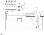
- Figure 3 shows a schematic view of a preferred embodiment of the fluid-bed granulator system according to the invention.
- the principle setup is identical with the setup described in figure 2 .
- the product screen (3) further comprises an exit for large on-size particles (3aL) and small one-size particles (3aS).
- large on-size particles” and “small on-size particles” refer to particles within the size range of "on-size” final product particles, e.g. preferably with a medium particle diameter between 2 mm and 4 mm.
- This setup is realized by utilizing a third (screen) mesh (3d3) between the above mentioned first (screen) mesh (3d1) and second (screen) mesh (3d2).
- This third (screen) mesh (3d3) separates the on-size particles into large on-size particles (3aL) with particle sizes above the mesh size of the third (screen) mesh (and below the first (screen) mesh) and into small on-size particles (3aS) below the mesh size of the third (screen) mesh (3d2) (and above the mesh size of the second (screen) mesh (3d2)).
- the exit for large on-size particles (3aL) and the exit for small one-size particles (3aS) are connected with the first splitter (5a), dividing the granule stream of large on-size particles (3aL) and/or small one-size particles (3aS) between the post processing unit (22) and a second splitter (5b) connected with the fluid-bed granulator (1).
- the exit for the undersized particles (3c) is connected with the second splitter (5b) and the exit for oversized particles (3b) is connected with the second splitter (5b) via the crusher (4).
- the second splitter (5b) collects and selects the ingoing streams from the before mentioned first splitter (5a) and the exits for undersized particles (3c) and crushed oversized particles (3b) for a further conveying into the fluid-bed granulator (1) via the recycle inlets (16).
- the crusher (4) can be directly connected with the first growing zone (7a1) via the corresponding valve (5b1). This connection is indicated by the dotted line.
- the processing and control unit (23) controls both the first splitter (5a) and the second splitter (5b) based on the product granules size or pre-cooled product granules size (after leaving the first cooler) provided by the particle size analyzer (24).
- the above described setup allows an automated adjustment of the seed particles provides by the second splitter (5b). If the product granules size increases, the second splitter (5b) can provide more undersized particles (3c) or crushed oversized particles (3b). If the product granules size decreases, the second splitter (5b) provides large on-size particles (3aL) and/or small on-size particles (3aS) via the first splitter (5a). This seed particle provision can be fully automated and controlled.
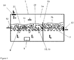
- Figure 4 shows the schematic view of the fluid-bed granulator system according to the invention comprising a fluid bed granulator (1) with a granulator space (1a) inside the fluid-bed granulator (1).
- a perforated plate (7) is located inside the granulator space (1a).
- Spray nozzles (8) are located on or above the perforated plate (7), a fluidization air inlet (9) is located below the perforated plate (2).
- Multiple supply lines for atomization air (10) and supply lines for a liquid melt (11) are connected to the spray nozzles (8).
- these supply lines (10, 11) can be combined in one line.
- the fluid-bed granulator (1) further comprises a granulation seeds inlet (12), preferably in connection with a not shown product sieve or crusher, a granulator outlet opening (13) and an air vent opening (14).
- the fluid-bed (21) is formed by the corresponding granular particles (20) utilizing the fluidization air from below the perforated plate (7).
- the fluidization air flow is indicated by arrows labeled (II)
- the flow direction of the fluid bed granular particles (20) is indicated by arrows labeled (I).
- the fluid-bed (21) is preferably divided by one or more partition plates (15).
- Figure 5 shows an experimental particle size distribution diagram.
- the data were obtained in a granulation plant with a granulation setup according to figure 1 (sample numbers 1 to 13) and granulation setup according to figure 2 (sample numbers 14 to 35).
- the samples were collected once a day.
- the bold line ( ⁇ ) shows on-size particles (3a) with a medium particle size between 2 to 4 mm.
- the first dotted line (----) shows undersized particles (3c) with a medium particle size below 2 mm.
- the second dotted line ( ⁇ ) shows oversized particles (3b) with a medium particle size above 4 mm.
- the first sample numbers show a significant variation in the particle size distribution.
- This fluctuation of the different particle size distribution can be significantly reduced by switching to a fluid-bed granulator system according to figure 2 .
- the advanced process control (APC) described in figure 2 is applied and activated in the samples 14 to 35.
- the product size of the on-size particles (3a) within the range of 2 mm to 4 mm stabilizes at a high value.
- Figure 6 shows a further experimental particle size distribution diagram of the size guide number (SGN) (y-axis) versus the sample number (x-axis).
- SGN size guide number
- the SGN corresponds to the on-size particle (3a) size in mm multiplied with hundred.
- the experimental setup and the corresponding data are identical with figure 5 .
- the conventional setup according to figure 1 shows a significant particle size fluctuation in the samples 1 to 14. By switching to the experimental setup of figure 2 at sample number 14, the fluctuations dampen, resulting in a very "monodisperse" particle size distribution.
- the inventive setup increases the number of on-size particles and significantly dampens the particle size fluctuations.
- the reduced fluctuations minimize the need for further manual process interventions, lowering the process cost by minimizing the amount of particles outside the product specification.
Landscapes
- Chemical & Material Sciences (AREA)
- Organic Chemistry (AREA)
- Chemical Kinetics & Catalysis (AREA)
- Life Sciences & Earth Sciences (AREA)
- Pest Control & Pesticides (AREA)
- Engineering & Computer Science (AREA)
- Combustion & Propulsion (AREA)
- Fertilizers (AREA)
Abstract
a.) a fluid-bed granulator (1)
b.) a first cooler (2) externally connected with the fluid-bed granulator (1) or forming an internal part of the fluid-bed granulator (1),
c.) a product screen (3) connected with the first cooler (2) wherein the product screen (3) at least comprises:
- an exit for on-size particles (3a);
- an exit for oversized particles (3b) and
- an exit for undersized particles (3c);
c.1) wherein the exit for undersized particles (3c) is connected with the fluid-bed granulator (1) and wherein the exit for oversized particles (3b) is connected with the fluid-bed granulator (1) via one or more crushers (4);
c.2) wherein the exit for on-size particles (3a) is connected with a first splitter (5a) and wherein the first splitter (5a) is connected with the fluid-bed granulator (1) and a post processing unit (22); and
wherein a particle size analyzer (24) is located between the fluid-bed granulator (1) and the product screen (3).
Description
- The invention relates to a fluid-bed granulator system for producing fertilizer granules with a defined size, a process for a particle size controlled granulation of urea containing particles, a urea granulation plant and the use of the fluid-bed granulator system for the production of fertilizer granules containing ammonia compounds.
- Due to a continuous world population growth, there is an ongoing need in providing reliable, easy producible and cheap fertilizers. These conventional fertilizers may contain nitrogen, phosphate, sulfur, potassium or micronutrients.
- A common, widely used fertilizer contains urea as its main component. The water soluble urea rapidly decomposes in the soil, providing ammonia and nitrate compounds. Based on the application, the fertilizer may contain only urea or a combination of urea with one or more of the before mentioned components, e.g. phosphate, sulfur, potassium or micronutrients.
- Urea can be produced on a large industrial scale by reacting ammonia with carbon dioxide via a (simplified) two-step reaction (e.g. in ULLMANN'S Encyclopedia of Industrial Chemistry, DOI: 10.1002/14356007):
2 NH3 + CO2 ⇄ H2N-COONH4 (1)
H2N-COONH4 ⇄ (NH2)2CO + H2O (2)
- Post synthesis process steps are necessary in order to provide a transportable and storable urea fertilizer. Common technical processes include diverse granulation technics like prilling, drum granulation or fluid-bed granulation. Especially prilling processes suffer from some critical drawbacks like relatively soft particles and sometimes deformed inhomogeneous particles.
- These problems can be avoided by using a fluid-bed granulation process, which results in harder, more stable and homogeneous granules. The resulting granular urea is particularly suitable for bulk blending operations. Furthermore, there is reduced segregation or mechanical damage during mixing and transporting of the urea based fertilizer.
- Examples of fluid-bed granulation process of urea can be found in
WO 2010/060535 A1 , e.g. in paragraphs [0025]-[0035],figure 1 or inUS 4,701,353 A ,DE 31 16 778 A1 andUS 4,219,589 A . - The fluid-bed granulation process is based on providing granulation seeds, which grow by absorbing very small droplets of a growth liquid. These small droplets can be provided via an "atomized" liquid urea melt. The term "atomized" used in the description refers to a mixing process of the liquid urea melt (or other suitable fertilizer melts) with a pressurized medium like air. This mixing process creates a liquid/gas emulsion or an aerosol of small droplets. The term "atomized" should therefore not be confused with a molecular separating process of atomic/covalent bonds. The produced droplets may have a medium size distribution around 1 µm to 200 µm. These small melt droplets accumulate and solidify on the surface of the granulation seeds, thereby increasing the size of the granulation particles. These fresh "in-situ" produced granules may commonly exhibit temperatures around 100 °C and are relatively soft. The particles further cool down in the fluid-bed of the granulator and/or in separate cooling equipment.
- The increased use of mechanical spreading systems in combination with precision farming techniques leads to ever more stringent requirements for the size distribution of granular fertilizers. Previously a typical size distribution would be 90% between 2 - 4 mm and 1% below 1 mm. Nowadays a typical size distribution are 95% between 2 - 4 mm, plus additional requirements such as 60% over 2.8 mm, or specific values for the SGN (size guide number) and Ul (uniformity index).
- The growth rate in a typical fluid bed granulation plant cannot be controlled precisely enough to produce such uniform size distributions. Therefore increasing efforts are required to understand and control the size distribution produced in the granulator.
- One such solution could be to provide more and better screening sections to screen off unwanted granule sizes. This however causes additional investment for equipment and building and produces more "off spec" (particle properties outside the product specification/insufficient product quality) product which must be recycled; at the same time the production rate is reduced. While significant efforts have been made to optimize screens and screen mesh sizes a continuous production of the high quality size grades remains difficult.
-
US 9,527,104 B2 -
GB 1,462,633 A -
EP 0 212 714 A1 -
EP 2 305 371 A1 -
US 3,516,813 A discloses a method for producing more uniform product size fertilizer pellets by suppressing the percentage of smaller intermediate size granules. -
EP 0 026 918 B1 -
WO 01/43861 A1 -
WO 2012/113473 A1 discloses a process for preparation of a granular urea product by granulating a urea solution in a fluidized bed, where said urea solution enters the fluidized bed by means of several urea inputs. - It is therefore an objective of the present invention to provide a fluid-bed granulator system with an increased output of size controlled particles with a decreased size distribution.
- The object of the present invention is solved by a fluid-bed granulator system according to
claim 1. Preferred embodiments of the invention are subject to the corresponding dependent claims. - The object of the present invention is also solved by a process for a particle size controlled granulation of urea containing particles. Preferred embodiments of the process are subject to the corresponding dependent claims.
- Another object of the present invention is the provision of a plant for the production of urea containing fertilizer granules.
- In a further aspect it is another object of the present invention to provide the use of the urea granulation plant for the production of fertilizer granules.
- The fluid-bed granulator system for producing fertilizer granules with a defined size at least comprises a fluid-bed granulator and a first cooler externally connected with the fluid-bed granulator or forming an internal part of the fluid-bed granulator. The term "connected" within the meaning of the invention generally refers to connection means which are able/suitable to transport or transfer process liquids, solids or gases, e.g. via pipes, ducts, pumps, hoses and further includes tanks, reservoirs and/or pumps. This definition includes connection means suitable for low pressure gaseous, solid and liquid mediums (below 1 bar) and high pressure (above 1 bar) gaseous, solid and liquid mediums. The term "connected" within the meaning of the invention includes a connection via further additional (including not mentioned) devices located (and connected) between the respective connected devices.
- In addition a product screen is connected (downstream of the first cooler) with the first cooler. The product screen (or sieve or screen mesh) separates the granular particles from the product cooler into on-size product particles within the desired product size and into oversized (above the desired product size) and undersized (below the desired product size) particles. This particle size separation and selection can be achieved e.g. by the use of different (screen) meshes (within the product screen) with a decreasing mesh size. Preferably, a minimum screen setup (in the direction of flow/top to bottom) would include a first (screen) mesh with a mesh size above the desired particle size and a second (screen) mesh with a mesh size below the desired particle size, thus dividing the product screen into three parts. Within the meaning of the invention, the term "above the desired particle size" preferably refers to mesh size slightly above the upper limit of the desired particle size (e.g. above 4 mm) and below the lower limit of the oversized particles. The actual mesh size may therefore vary e.g. in a range of 5 % to 25 % in dependence of the before mentioned particle size. Within the meaning of the invention, the term "below the desired particle size" preferably refers to mesh size slightly below the lower limit of the desired particle size (e.g. below 2 mm) and above the upper limit of the undersized particles. The actual mesh size may therefore vary e.g. in a range of 5 % to 25 % in dependence of the before mentioned particle size. The product screen further comprises an exit for oversized particles, e.g. above the first (screen) mesh, and an exit for undersized particles, e.g. below the second (screen) mesh. The exit for the undersized particles is connected with the fluid-bed granulator and the exit for oversized particles is connected with the granulator via a crusher or a similar device. The undersized particles and/or crushed oversized particles act as seed particles in the fluid-bed granulator. Within the meaning of the invention, the term "crusher" comprises comminution devices for crushing, grinding, milling, cutting, vibrating and/or breaking, e.g. crusher, mills,... According to the invention the product screen further comprises an exit for on-size particles, preferably with a medium particle diameter between 2 mm and 4 mm.
- In addition the exit for the on-size particles is connected with a first splitter and wherein the (exit of the) first splitter is simultaneously connected with the fluid-bed granulator and a post processing unit. The term "splitter" includes devices (like e.g. valves or switches) allowing a changeable flow of the particles to different parts of the processing parts. The first splitter allows an adjustable reuse of the on-size particles as seed particles in the fluid-bed granulator. Within the meaning of the invention the term "adjustable" includes devices for manually, pneumatically and/or electronically (including automatically) controlling the splitter, thereby varying the amount of on-size particles passing the splitter and entering the fluid-bed granulator. Depending on the particle size distribution of the granular particles leaving the fluid-bed granulator, the splitter allows a reuse of larger (in comparison to the undersized or crushed particles) on-size particles as seed particles in the fluid-bed granulator or a conveying of these particles into the post processing unit. The splitter allows a distribution and regulation of the particle stream originating from the exit for on-sized particles towards the recycle inlets of the fluid- bed granulator and/or the post processing unit. The term "post processing unit" includes well known devices for, weighing, transporting and packaging of the final product particles.
- According to the invention a particle size analyzer is located between the fluid-bed granulator and the product screen. The particle size analyzer is able to determine the particle size of the product particles leaving the fluid-bed granulator. Examples of (online) particle size analyzers are well known in the art, e.g. an online particle size analyzer (e.g. HAVER CPA 2-1, Outotec RockSense®). The output of the online particle analyzer is then preferably used by an advanced process control system (APC) which independently controls the granule size distribution in the product particles. This seed particle size adjustment surprisingly dampens the oscillations in the recycle and product flows which often occur in granulation plants, after a process change or upset. These oscillations can lead to significant disturbances in the plant operation and in the size distribution of the product. Without the oscillations of the flows the plant operation and the product quality are significantly improved. Depending on the size of the product granules leaving the granulator or the first cooler, either more/less (larger) on-size particles or undersized and crushed oversized particles can be used as seed granules in granulator. This seed particle size adjustment surprisingly lowers the otherwise occurring wave-like particle size fluctuations. The effect of this 'dampening' of the product size distributions is shown in
Fig. 5 - Preferably the product screen further comprises an exit for large on-size particles and small one-size particles. The term "large on-size particles" and "small on-size particles" refer to particles within the size range of "on-size" final product particles, e.g. preferably with a medium particle diameter between 2 mm and 4 mm. This setup can be e.g. realized by utilizing a third (screen) mesh between the above mentioned first (screen) mesh and second (screen) mesh. This third (screen)mesh separates the on-size particles into large on-size particles with particle sizes above the mesh size of the third (screen) mesh (and below the first (screen) mesh) and into small on-size particles below the mesh size of the third (screen) mesh(and above the mesh size of the second (screen) mesh). In addition the exit for large on-size particles and the exit for small on size particles are connected with the first splitter and wherein the first splitter is simultaneously connected with the fluid-bed granulator and a post processing unit. This preferred setup allows a further "fine tuning" of the product granule size by further varying the size of the seed granules.
- Preferably, the product screen comprises (from top to bottom) three inner (screen) meshes with a decreasing mesh size. If required, the product screen can comprises (from top to bottom) three, four or five inner (screen) meshes. These (screen) meshes may be connected to a third, fourth or fifth (and so on) splitter. By this way different product size distributions can be produced simultaneously
- Preferably, the mesh size of the inner (screen) meshes is in the range of 0.1 mm to 10 mm, preferably in the range of 1 mm to 5 mm.
- Preferably, the first splitter and/or the exit for oversized particles via the crusher and/or the exit for undersized particles are connected with (preferably the input of) a second splitter. The (preferably output of the) second splitter is connected with the recycle inlets of the fluid-bed granulator. The splitter allows a distribution and regulation of the particle streams originating from the first splitter and/or the exit for oversized particles via the crusher and/or the exit for undersized particles towards the recycle inlets of the fluid- bed granulator.
- More preferably the particle size analyzer is (electronically) connected with the first splitter and/or the second splitter. Even more preferably the particle size analyzer is electronically connected with the first and/or second splitter via a processing and control unit. This connection setup allows an online measuring and simultaneous, preferably an automated, adjusting of the product particle size within the fluid-bed granulator via the size of the introduced seed particles provided (released) by the first splitter and/or second splitter.
- Preferably, the Fluid-bed granulator comprises a granulator space inside the fluid-bed granulator. The fluid-bed granulator further comprises a perforated plate located inside the granulator space and spray nozzles located in, on or beside the perforated plate. Preferably, the spray nozzles are attached to the perforated plate. A fluidization air inlet, preferably located below the perforated plate, provides the necessary fluidization air for the fluid bed of fertilizer granules. The term "fluidization air" includes air or inert gases like CO2, nitrogen, argon or mixtures thereof. The spray nozzles are connected with supply lines for atomization air and supply lines for a liquid melt, preferably a liquid melt containing urea. Within the meaning of the invention, the term "melt" include salt melts and concentrated salt solution and mixtures thereof, preferably solutions containing more than 50 wt. % salt. Optionally, these supply lines for air and melt can be combined in one line. In addition, the fluid-bed granulator comprises a granulation seeds inlet. The term "a granulation seeds inlet" comprises internal and external devices, lines and openings for the introduction of granular seeds. The term "internal" refers to the production of granular seeds within the granulator. The term "external" refers to the providing provision or production of granular seeds from outside the granulator, e.g. via sieves or crushers outside the fluid-bed granulator. Furthermore the fluid-bed granulator comprises a granulator outlet opening and an air vent opening. Optionally, the granulator space comprises separating walls with optionally integrated openings. These separating walls may further alter and modify the speed of the fluid bed towards the granulator outlet opening. Dust, e.g. urea dust, and chemical vapors like ammonia, which are created or released during the granulation process, are removed in a separate scrubber unit. Preferably, the scrubber unit comprises at least a dust removing scrubber and an ammonia removing scrubber. Examples of suitable scrubbers can be found in
WO 2005/032696 A1 (figure 1 ) orWO2010/60535 A1 - Preferably, the first fluid-bed cooler comprises at least a cooler space inside the fluid-bed cooler and a perforated plate located inside the cooler space. A fluidization air inlet, preferably located below the perforated plate, provides the necessary fluidization air for the fluid bed of fertilizer granules. The fertilizer granules are conveyed into the cooler via a product inlet. The cooled fertilizer granules leave the fluid-bed cooler via a cooler outlet opening. Furthermore the fluid-bed cooler comprises an air vent opening. Dust, e.g. urea dust, and chemical vapors like ammonia, which are created or released during the cooling process, are removed in a separate scrubber unit via the air vent opening. Preferably, the scrubber unit comprises at least a dust removing scrubber. In a preferred embodiment, the recycle cooler uses air or water as cooling medium.
- Preferably, the perforated plate comprises (in the direction of the granular flow) at least a growing zone and a cooling zone, more preferably (in the direction of flow) at least a first growing zone, a first cooling zone, a second growing zone and a second cooling zone. The term "growing zone" refers to a section of the perforated plate inside the fluid-bed granulator. The growing zone marks a section, wherein the particle size and weight is increased, e.g. due absorbing urea droplets (released from the spraying nozzles). The term "cooling zone" refers to another section of the perforated plate inside the fluid-bed granulator. The cooling zone marks a section, wherein the particle size and weight is kept relatively constant (besides temperature related shrinking effects) and wherein the temperature of the particles is reduced. The combination of cooling and growing zones supports the temperature control of the fluid-bed and helps to prevent the overheating of the particles. Preferably, the cooling zone does not comprise spray nozzles.
- Preferably, the (output of the) first splitter and/or the (output of the) second splitter are connected with the growing zone and/or the cooling zone via recycle inlets. Even more preferably the first splitter and/or the second splitter are connected with the first growing zone and/or the second growing zone via the recycle inlets. The distribution of the seed particles originating from the first and/or second splitter allows an even finer particle size adjustment.
- In a preferred embodiment of the invention the first splitter and/or the second splitter are electronically connected with a processing and control unit. In addition the processing and control unit is electronically connected with the particle size analyzer. This setup allows an automated regulation (APC advanced process control) of the product granules size, preferably without any manual intervention or regulation.
- Preferably, the (more preferably input of the) second splitter is connected with the (preferably output) of the first splitter and/or the exit for oversized particles via the crusher and/or the exit for undersized particles. In addition the (preferably output of the) second splitter is connected with the recycle inlets of the fluid-bed granulator and wherein the recycle inlets are connected with one or more growing zones and/or cooling zones.
- Preferably the product screen (or sieve) comprises four inner (screen) meshes with a decreasing mesh size or five inner (screen) meshes with a decreasing mesh size.
- Preferably the product screen is connected with a third splitter and/or a fourth splitter. Simultaneously the third splitter and/or the fourth splitter are connected with the fluid-bed granulator and the post processing unit. Even more preferably the third splitter and/or a fourth splitter are controlled via the processing and control unit.
- The invention further comprises a process for a particle size controlled granulation of urea containing particles at least comprising the following steps. In a first step, seed granules are conveyed into a fluid-bed granulator. The seed granules are processed (granulated) in the fluid-bed granulator and transferred into product granules. The said product granules are conveyed to a first cooler. The first cooler can be externally connected with the fluid-bed granulator or form an internal part of the fluid-bed granulator. Follow-up, pre-cooled product granules are received.
- The said pre-cooled product granules are conveyed into a product screen comprising an exit for on-size particles, an exit for oversized particles and an exit for undersized particles. The exit for on-size particles is connected with a splitter. The splitter is further connected with the fluid-bed granulator and a post processing unit. Follow-up, the undersized particles are conveyed into the fluid-bed granulator, the on-size particles are conveyed into the post processing unit and the oversized particles are conveyed into a crusher. The crusher provides crushed particles, which are conveyed back into the fluid-bed granulator. The on-size particles are conveyed to the fluid-bed granulator and/or the post processing unit via the splitter.
- The inventive process is characterized in that the size of the product granules or pre-cooled product granules is measured by a particle size analyzer and the obtained product granules size or pre-cooled product granules size is compared to a predefined "threshold" value. Preferably, this predefined "threshold" value defines a lower particle size threshold value. The amount of on-size particles conveyed to the fluid-bed granulator is increased, if the size of the product granules drops below the predefined value. Within the meaning of the invention, the term "drops below" may include a suitable delay time before actually increasing the amount of large on-size particles. Within the meaning of the invention, the term "the amount of on-size particles conveyed to the fluid-bed granulator is increased" includes an increase based on zero conveyed on-size particles if the before measured sizes of the product granules or pre-cooled product granules were above the predefined "threshold" value.
- Preferably, the product screen comprises (from top to bottom) three inner (screen) meshes with a decreasing mesh size. The third middle (screen)mesh separates the on-size particles into large on-size particles with particle sizes above the mesh size of the third (screen) mesh (and below the first screen) and into small on-size particles below the mesh size of the third (screen) mesh (and above the mesh size of the second (screen) mesh). In addition the exit for large on-size particles and the exit for small on size particles are connected with a first splitter and wherein the first splitter is simultaneously connected with the fluid-bed granulator and a post processing unit. This preferred setup allows a further "fine tuning" of the product granule size by further varying the size of the seed granules.
- More preferably the particle size analyzer is electronically connected with the splitter and/or the first splitter and/or the second splitter. Even more preferably the particle size analyzer is electronically connected with the splitter via a processing and control unit. This connection setup allows an online measuring and simultaneous, preferably an automated, adjusting of the product particle size within the fluid-bed granulator via the size of the introduced seed particles based on the large on-size particles. Simultaneously, the seed particles and/or a part of the seed particles are provided via the before described splitter.
- In a preferred embodiment, the size of the product granules or pre-cooled product granules is measured by the particle size analyzer and the obtained product granules size or pre-cooled product granules size is compared to a second predefined value. The second predefined value defines an upper particle size threshold value and the amount of undersized particles and/or crushed particles is increased, if the size of the product granules drops above the predefined second value. The "use" of a second predefined threshold value allows an automated control of the product particle size, by increasing the amount of on-size particles if the product particle size decreases. On the other hand, by increasing the amount of undersized particles and/or crushed particles an increase of the product particle size can be corrected. Preferably, the before mentioned steps are controlled and regulated by a suitable computer program and corresponding hardware.
- Preferably the undersized particles and/or crushed particles and/or on-size particles are introduced via recycle inlets into one or more growing zone(s) and/or cooling zone(s). The term "growing zone" refers to a section of the perforated plate inside the fluid-bed granulator. The growing zone marks a section, wherein the particle size and weight is increased, e.g. due absorbing urea droplets. The term "cooling zone" refers to another section of the perforated plate inside the fluid-bed granulator. The cooling zone marks a section, wherein the particle size and weight is kept relatively constant and wherein the temperature of the particles is reduced. The combination of cooling and growing zones supports the temperature control of the fluid-bed and helps to prevent the overheating of the particles. Preferably, the cooling zone does not comprise spray nozzles.
- The invention further comprises a urea granulation plant comprising an inventive fluid-bed granulator system as described above.
- The invention further comprises an inventive fluid-bed granulator system as previously described for the production of fertilizer granules containing ammonia compounds, nitrates, phosphates, urea, elemental sulfur, ammonia sulfate, UAS (urea - ammonia sulfate), granulation additives, phase mixing additives, micronutrients and/or mixtures thereof. The term "granulation additives" comprises formaldehyde or formaldehyde free granulation additives like a combination of at least one amino-group containing polymer or oligomer and at least one functional polyvinyl compound, preferably a combination of polyethylene imine and polyvinyl alcohol, a compound selected from the group of aliphatic dicarboxylic acids and anhydrides, aliphatic tricarboxylic acids and anhydrides, aromatic Dicarboxylic acids and anhydrides, and/or aliphatic C2-C8 dialdehyde. The term "phase mixing" additives comprises anionic, cationic or non-ionic surfactants, more preferably salts and ester of fatty acids, SDS (Sodium dodecylsulfate), AOT (Dioctyl sodium sulfosuccinate), lignin(e) and/or lignin(e) sulfonate and/or mixtures or derivates thereof.
- The invention is further described in the following exemplary figures. The figures are meant for illustrative purpose only and do not restrict the scope of protection. The figures are not true to scale.
-
Figure 1 shows an exemplary schematic view of a fluid-bed granulator system, -
Figure 2 shows a schematic view of a fluid-bed granulator system according to the invention, -
Figure 3 shows a schematic view of a preferred embodiment of the fluid-bed granulator system according to the invention, -
Figure 4 shows a schematic view of a fluid-bed granulator according to the invention, -
Figure 5 shows an experimental particle size distribution diagram and -
Figure 6 shows a further experimental particle size distribution diagram of the size guide number (SGN). -
Figure 1 shows an exemplary schematic view of a fluid-bed granulator system. The fluid-bed granulator system comprises a fluid-bed granulator (1) and a first cooler (2) connected with the fluid-bed granulator (1). The term "connected" within the meaning of the invention generally refers to connection means which are able/suitable to transport or transfer process liquids or gases, e.g. pipes, ducts, pumps, hoses and further includes tanks, reservoirs and/or pumps. This definition includes connection means suitable for low pressure gaseous and liquid mediums (below 1 bar) and high pressure (above 1 bar, preferably above 10 bar) gaseous and liquid mediums. A product screen (3) is connected with the first cooler (2). The product screen (3) (or sieve) separates the granular particles from the product cooler into product particles (3a) within the desired product size and into oversized (above the desired product size) particles (3b) and undersized (below the desired product size) particles (3c). The minimum screen (3) setup would include a first (screen) mesh (3d1) with a mesh size above the desired particle size and a second (screen)mesh (3d2) below the desired particle size, thus dividing the product screen into three parts. The product screen further comprises an exit for final product particles (3a), e.g. between the first (screen) mesh and second (screen) mesh, an exit for oversized particles (3b), e.g. above the first (screen) mesh, and an exit for undersized particles (3c), e.g. below the second (screen) mesh. The exit for the undersized particles (3a) is connected via the recycle inlet (16) with the fluid-bed granulator (1) and the exit for oversized particles (3b) is connected with the granulator (1) via a crusher (4) or a similar device, resulting in crushed particles (3d). The final product particles (3a) are transferred to suitable further post processing units (22) like scales and packaging devices. -
Figure 2 shows a schematic view of the fluid-bed granulator system according to the invention. The principle setup is identical with the setup described infigure 1 . The product screen (3) (or sieve) separates the granular particles from the product cooler (2) into product particles within the desired product size (on-size) and into oversized (above the desired product size) and undersized (below the desired product size) particles. This includes a first (screen) mesh (3d1) with a mesh size above the desired particle size and a second (screen) mesh (3d2) below the desired particle size, thus dividing the product screen into three parts. The product screen (3) further comprises an exit for oversized particles (3b), e.g. above the first (screen) mesh, and an exit for undersized particles (3c), e.g. below the second (screen) mesh (3d2). The exit for the undersized particles (3c) is connected with the fluid-bed granulator (1) and the exit for oversized particles (3b) is connected with the fluid-bed granulator (1) via a crusher (4) or a similar device. In addition the exit for on-size particles (3a) is connected with a first splitter (5a). The first splitter (5a) is connected with the fluid-bed granulator (1) and the post processing unit (22). The first splitter (5a) allows an adjustable reuse of on-size particles (3aL) in the fluid-bed granulator. Within the meaning of the invention the term "adjustable" includes devices for manually or electronically controlling the splitter, thereby varying the amount of on-size (3a) particles passing the first splitter (5a) and entering the fluid-bed granulator (1). Depending on the particle size distribution of the granular particles leaving the fluid-bed granulator, the first splitter (5a) allows a reuse of on-size particles (3a) or a conveying of these on-size particles (3a) into the post processing unit. A particle size analyzer (24) is located between the fluid-bed granulator (1) and the product screen (3). The particle size analyzer (24) is able to determine the particle size of the product particles leaving the fluid-bed granulator (1). Examples of (online) particle size analyzers are well known in the art, e.g. an online particle size analyzer (HAVER CPA 2-1, Outotec RockSense®). The output of the online particle analyzer is then used by a processing and control unit (23) which may independently (APC-advanced process control) control and adjust the granule size distribution in the product particles. The particle size analyzer (15) is electronically connected with the first splitter (5a) via the processing and control unit (23). This connection setup allows an online measuring and simultaneous, preferably an automated, adjusting of the product particle size within the fluid-bed granulator via the size of the introduced seed particles. -
Figure 3 shows a schematic view of a preferred embodiment of the fluid-bed granulator system according to the invention. The principle setup is identical with the setup described infigure 2 . The product screen (3) further comprises an exit for large on-size particles (3aL) and small one-size particles (3aS). The term "large on-size particles" and "small on-size particles" refer to particles within the size range of "on-size" final product particles, e.g. preferably with a medium particle diameter between 2 mm and 4 mm. This setup is realized by utilizing a third (screen) mesh (3d3) between the above mentioned first (screen) mesh (3d1) and second (screen) mesh (3d2). This third (screen) mesh (3d3) separates the on-size particles into large on-size particles (3aL) with particle sizes above the mesh size of the third (screen) mesh (and below the first (screen) mesh) and into small on-size particles (3aS) below the mesh size of the third (screen) mesh (3d2) (and above the mesh size of the second (screen) mesh (3d2)). The exit for large on-size particles (3aL) and the exit for small one-size particles (3aS) are connected with the first splitter (5a), dividing the granule stream of large on-size particles (3aL) and/or small one-size particles (3aS) between the post processing unit (22) and a second splitter (5b) connected with the fluid-bed granulator (1). The exit for the undersized particles (3c) is connected with the second splitter (5b) and the exit for oversized particles (3b) is connected with the second splitter (5b) via the crusher (4). The second splitter (5b) collects and selects the ingoing streams from the before mentioned first splitter (5a) and the exits for undersized particles (3c) and crushed oversized particles (3b) for a further conveying into the fluid-bed granulator (1) via the recycle inlets (16). The particle stream leaving the second splitter is conveyed to different growing zones (7a1, 7a2, 7ai, with i = 3, 4, 5, 6, ...) and/or different cooling zones (7b1, 7b2, 7bi, with i = 3, 4, 5, 6, ...) via valves (5b1, 5b2, 5b3, 5b4, 5bi with i = 3, 4, 5, 6, ...). Alternatively or additionally, the crusher (4) can be directly connected with the first growing zone (7a1) via the corresponding valve (5b1). This connection is indicated by the dotted line. The processing and control unit (23) controls both the first splitter (5a) and the second splitter (5b) based on the product granules size or pre-cooled product granules size (after leaving the first cooler) provided by the particle size analyzer (24). The above described setup allows an automated adjustment of the seed particles provides by the second splitter (5b). If the product granules size increases, the second splitter (5b) can provide more undersized particles (3c) or crushed oversized particles (3b). If the product granules size decreases, the second splitter (5b) provides large on-size particles (3aL) and/or small on-size particles (3aS) via the first splitter (5a). This seed particle provision can be fully automated and controlled. -
Figure 4 shows the schematic view of the fluid-bed granulator system according to the invention comprising a fluid bed granulator (1) with a granulator space (1a) inside the fluid-bed granulator (1). A perforated plate (7) is located inside the granulator space (1a). Spray nozzles (8) are located on or above the perforated plate (7), a fluidization air inlet (9) is located below the perforated plate (2). Multiple supply lines for atomization air (10) and supply lines for a liquid melt (11) are connected to the spray nozzles (8). Optionally, these supply lines (10, 11) can be combined in one line. The fluid-bed granulator (1) further comprises a granulation seeds inlet (12), preferably in connection with a not shown product sieve or crusher, a granulator outlet opening (13) and an air vent opening (14). The fluid-bed (21) is formed by the corresponding granular particles (20) utilizing the fluidization air from below the perforated plate (7). The fluidization air flow is indicated by arrows labeled (II), the flow direction of the fluid bed granular particles (20) is indicated by arrows labeled (I). The fluid-bed (21) is preferably divided by one or more partition plates (15). -
Figure 5 shows an experimental particle size distribution diagram. The data were obtained in a granulation plant with a granulation setup according tofigure 1 (sample numbers 1 to 13) and granulation setup according tofigure 2 (sample numbers 14 to 35). The samples (Sample number) were collected once a day. The bold line (―) shows on-size particles (3a) with a medium particle size between 2 to 4 mm. The first dotted line (----) shows undersized particles (3c) with a medium particle size below 2 mm. The second dotted line (▪▪▪▪) shows oversized particles (3b) with a medium particle size above 4 mm. The first sample numbers show a significant variation in the particle size distribution. This fluctuation of the different particle size distribution can be significantly reduced by switching to a fluid-bed granulator system according tofigure 2 . The advanced process control (APC) described infigure 2 is applied and activated in thesamples 14 to 35. The product size of the on-size particles (3a) within the range of 2 mm to 4 mm stabilizes at a high value. -
Figure 6 shows a further experimental particle size distribution diagram of the size guide number (SGN) (y-axis) versus the sample number (x-axis). The SGN corresponds to the on-size particle (3a) size in mm multiplied with hundred. The experimental setup and the corresponding data are identical withfigure 5 . The conventional setup according tofigure 1 shows a significant particle size fluctuation in thesamples 1 to 14. By switching to the experimental setup offigure 2 atsample number 14, the fluctuations dampen, resulting in a very "monodisperse" particle size distribution. - Thereby, the inventive setup increases the number of on-size particles and significantly dampens the particle size fluctuations. The reduced fluctuations minimize the need for further manual process interventions, lowering the process cost by minimizing the amount of particles outside the product specification.
-
- (1)
- fluid-bed granulator
- (1a)
- granulator space
- (2)
- first cooler
- (3)
- product screen
- (3aL)
- large (final product) on-size particles
- (3aS)
- small (final product) on-size particles
- (3b)
- oversized particles
- (3c)
- undersized particles
- (3d)
- crushed particles
- (3d1)
- first (screen) mesh
- (3d2)
- second (screen) mesh
- (3d3)
- third (screen) mesh
- (5a)
- first splitter
- (5b)
- second splitter
- (5b1)
- valve
- (5b2)
- valve
- (5b3)
- valve
- (5b4)
- valve
- (7)
- perforated plate
- (7a)
- growing zone
- (7b)
- cooling zone
- (8)
- spray nozzles
- (9)
- fluidization air inlet
- (10)
- supply lines for atomization air
- (11)
- supply lines for a liquid melt
- (12)
- granulation seeds inlet
- (13)
- granulator outlet opening
- (14)
- air vent opening
- (15)
- partition plates
- (16)
- recycle inlet
- (20)
- granular particles
- (21)
- fluid-bed
- (22)
- post processing units
- (23)
- processing and control unit
- (24)
- particle size analyzer
Claims (18)
- Fluid-bed granulator system for producing fertilizer granules with a defined size at least comprising:a.) a fluid-bed granulator (1)b.) a first cooler (2) externally connected with the fluid-bed granulator (1) or forming an internal part of the fluid-bed granulator (1),c.) a product screen (3) connected with the first cooler (2) wherein the product screen (3) at least comprises:- an exit for on-size particles (3a);- an exit for oversized particles (3b) and- an exit for undersized particles (3c);c.1) wherein the exit for undersized particles (3c) is connected with the fluid-bed granulator (1) and wherein the exit for oversized particles (3b) is connected with the fluid-bed granulator (1) via one or more crushers (4);c.2) wherein the exit for on-size particles (3a) is connected with a first splitter (5a) and wherein the first splitter (5a) is connected with the fluid-bed granulator (1) and a post processing unit (22); andwherein a particle size analyzer (24) is located between the fluid-bed granulator (1) and the product screen (3).
- Fluid-bed granulator system according to claim 1, wherein the product screen (3) comprises an exit for large on-size particles (3aL) and an exit for small on-size particles (3aS).
- Fluid-bed granulator system according to claim 2, wherein the product screen (3) comprises three inner (screen) meshes (3d1, 3d3, 3d2) with a decreasing mesh size.
- Fluid-bed granulator system according to any one of claims 1 to 3, wherein the mesh size of the inner (screen)- meshes (3d1, 3d3, 3d2) is in the range of 0.1 mm to 10 mm, preferably in the range of 1 mm to 5 mm.
- Fluid-bed granulator system according to any one of claims 1 to 4, wherein- the first splitter (5a); and/or- the exit for oversized particles (3b) via the crusher (4); and/or- the exit for undersized particles (3c);are (ingoing) connected with a second splitter (5b), wherein the (output of the) second splitter is connected with recycle inlets (16) of the fluid-bed granulator (1).
- Fluid-bed granulator system according to any one of claims 1 to 5, wherein the particle size analyzer (24) is electronically connected with the first splitter (5a) and/or the second splitter (5b), preferably the particle size analyzer (24) is electronically connected via a processing and control unit (23).
- Fluid-bed granulator system according to any one of claims 1 to 6, wherein the fluid-bed granulator comprises a perforated plate (7) and wherein the perforated plate (7) at least comprises (in the direction of flow) at least a growing zone (7a) and a cooling zone (7b), preferably (in the direction of flow) at least a first growing zone (7a1), a first cooling zone (7b1), a second growing zone (7a2) and a second cooling zone (7b2).
- Fluid-bed granulator system according to claim 7, wherein the first splitter (5a) and/or the second splitter (5b) are connected with the growing zone (7a) and/or the cooling zone (7b) via the recycle inlets (16), preferably wherein the first splitter (5a) and/or the second splitter (5b) are connected with the first growing zone (7a1) and/or the second growing zone (7a2) via the recycle inlets (16).
- Fluid-bed granulator system according to any one of claim 1 to 8, wherein the first splitter (5a) and/or the second splitter (5b) are electronically connected with the processing and control unit (23); and wherein the processing and control unit (23) is electronically connected with the particle size analyzer (24).
- Fluid-bed granulator system according to any one of claim 1 to 9, wherein the second splitter (5b) is connected with- the first splitter (5a); and/or- the exit for oversized particles (3b) via the crusher (4); and/or- the exit for undersized particles (3c); andwherein the second splitter (5b) is connected with the recycle inlets (16) of the fluid-bed granulator (1) and wherein the recycle inlets (16) are connected with one or more growing zones (7ai) and/or cooling zone (7bi).
- Fluid-bed granulator system according to any one of claims 1 to 10, wherein the product screen (3) comprises four inner (screen) meshes (3d1, 3d3, 3d4, 3d2) with a decreasing mesh size or five inner (screen) meshes (3d1, 3d3, 3d4, 3d5, 3d2) with a decreasing mesh size.
- Fluid-bed granulator system according to claim 11, wherein the product screen (3) is connected with:- a third splitter (5c) and/or a fourth splitter (5d); and wherein- the third splitter (5c) and/or a fourth splitter (5d) are connected with the fluid-bed granulator (1) and the post processing unit (22); and wherein preferably- the third splitter (5c) and/or a fourth splitter (5d) are controlled via the processing and control unit (23).
- Process for a particle size controlled granulation of urea containing particles at least comprising the following steps:• conveying of seed granules into a fluid-bed granulator (1);• granulating of said seed granules and receiving product granules;• conveying of said product granules to a first cooler (2) externally connected with the fluid-bed granulator (1) or forming an internal part of the fluid-bed granulator (1) and receiving pre-cooled product granules;• conveying said pre-cooled product granules into a product screen (3) comprising:- an exit for oversized particles (3b);and- an exit for undersized particles (3c); and- an exit for on-size particles (3a);wherein the exit for on-size particles (3a) is connected with a first splitter (5a) and wherein the first splitter (5a) is connected with the fluid-bed granulator (1) and a post processing unit (22);• conveying the undersized particles (3c) into the fluid-bed granulator (1);• conveying the oversized particles (3b) into a crusher (4) and receiving crushed particles (3d) and conveying the crushed particles (3d) into the fluid-bed granulator (1),• conveying the on-size particles (3a) via the first splitter (5) to the fluid-bed granulator (1) and/or the post processing unit (22), whereina.) the size of product granules or pre-cooled product granules is measured by a particle size analyzer (15) and the obtained product granules size or pre-cooled product granules size is compared to a predefined value, wherein the predefined value defines a lower particle size threshold value andb.) the amount of on-size particles (3a) conveyed to the fluid-bed granulator is increased, if the size of the product granules drops below the predefined value.
- Process according to claim 13, wherein the product screen (3) comprises an exit for large on-size particles (3aL) and an exit for small on-size particles (3aS), preferably wherein the product screen (3) comprises three inner (screen) meshes (3d1, 3d3, 3d2) with a decreasing mesh size.
- Process according to any one of claims 13 to 14, wherein the size of the product granules or pre-cooled product granules is measured by the particle size analyzer (15) and the obtained product granules size or pre-cooled product granules size is compared to a second predefined value, wherein the second predefined value defines a upper particle size threshold value and the amount of undersized particles (3c) and/or crushed particles (3d) is increased, if the size of the product granules drops above the predefined second value.
- Process according to any one of claims 13 to 15, wherein the undersized particles (3c) and/or crushed particles (3d) and/or on-size particles are introduced via recycle inlets (16) into one or more growing zones (7ai) and/or cooling zone (7bi)
- Urea granulation plant comprising a fluid-bed granulator system according to any one of the claims 1 to 12.
- Use of the Fluid-bed granulator system according to any one of the claims 1 to 12 for the production of fertilizer granules containing ammonia compounds, nitrates, phosphates, urea, elemental sulfur, ammonia sulfate, UAS (urea - ammonia sulfate), granulation additives, emulgation additives and/or mixtures thereof.
Priority Applications (5)
| Application Number | Priority Date | Filing Date | Title |
|---|---|---|---|
| EP18183433.4A EP3593898B1 (en) | 2018-07-13 | 2018-07-13 | Producing fertilizer granules with a defined size distribution |
| CA3048236A CA3048236C (en) | 2018-07-13 | 2019-06-28 | Fluid-bed granulator system and process for particle size controlled granulation of urea-containing particles |
| US16/459,935 US20200017416A1 (en) | 2018-07-13 | 2019-07-02 | Producing fertilizer granules with a defined size distribution |
| RU2019121650A RU2717788C1 (en) | 2018-07-13 | 2019-07-11 | Obtaining fertilizer granules with given size distribution |
| US17/587,828 US12102976B2 (en) | 2018-07-13 | 2022-01-28 | Plants and systems for producing fertilizer granules with a defined size distribution |
Applications Claiming Priority (1)
| Application Number | Priority Date | Filing Date | Title |
|---|---|---|---|
| EP18183433.4A EP3593898B1 (en) | 2018-07-13 | 2018-07-13 | Producing fertilizer granules with a defined size distribution |
Publications (2)
| Publication Number | Publication Date |
|---|---|
| EP3593898A1 true EP3593898A1 (en) | 2020-01-15 |
| EP3593898B1 EP3593898B1 (en) | 2021-09-01 |
Family
ID=62951943
Family Applications (1)
| Application Number | Title | Priority Date | Filing Date |
|---|---|---|---|
| EP18183433.4A Active EP3593898B1 (en) | 2018-07-13 | 2018-07-13 | Producing fertilizer granules with a defined size distribution |
Country Status (4)
| Country | Link |
|---|---|
| US (2) | US20200017416A1 (en) |
| EP (1) | EP3593898B1 (en) |
| CA (1) | CA3048236C (en) |
| RU (1) | RU2717788C1 (en) |
Families Citing this family (2)
| Publication number | Priority date | Publication date | Assignee | Title |
|---|---|---|---|---|
| EP3593898B1 (en) * | 2018-07-13 | 2021-09-01 | thyssenkrupp Fertilizer Technology GmbH | Producing fertilizer granules with a defined size distribution |
| EP4032606A1 (en) * | 2021-01-21 | 2022-07-27 | Yara International ASA | Hopper comprising cooling elements |
Citations (16)
| Publication number | Priority date | Publication date | Assignee | Title |
|---|---|---|---|---|
| US3398191A (en) * | 1963-12-09 | 1968-08-20 | Cominco Ltd | Process for the production of granular nitrogenous compounds |
| US3516813A (en) | 1968-07-01 | 1970-06-23 | Benjamin Gilbert Smith | Method for production of pelleted fertilizer with controlled feed particle size |
| GB1462633A (en) | 1973-04-10 | 1977-01-26 | Fisons Ltd | Granulating urea |
| US4219589A (en) | 1977-06-09 | 1980-08-26 | Compagnie Neerlandaise De L'azote | Process for urea granulation |
| DE3116778A1 (en) | 1980-05-12 | 1982-02-11 | Compagnie Néerlandaise de l'Azote S.A., Bruxelles | METHOD FOR PRODUCING SEEDS CONSTRUCTED FROM A CORE AND A HELL |
| EP0026918B1 (en) | 1979-10-08 | 1984-05-16 | Toyo Engineering Corporation | Granulation process |
| EP0212714A1 (en) | 1985-07-26 | 1987-03-04 | Stamicarbon B.V. | Process for the preparation of granules and granules obtained by this process |
| US4701353A (en) | 1983-08-27 | 1987-10-20 | Unie Van Kunstmestfabrieken B.V. | Process for the preparation of granules |
| US5779945A (en) * | 1996-04-15 | 1998-07-14 | Dsm N.V. | Process for producing granules |
| WO2001043861A1 (en) | 1999-12-15 | 2001-06-21 | Norsk Hydro Asa | A method and a device for processing a solution, melt, suspension, emulsion, slurry or solids into granules |
| WO2005032696A1 (en) | 2003-10-02 | 2005-04-14 | Uhde Gmbh | Method for removing ammonia and dust from a waste gas that results during the production of fertilizers |
| WO2010060535A1 (en) | 2008-11-28 | 2010-06-03 | Uhde Fertilizer Technology B.V. | Urea granulation process with an acidic scrubbing system and the subsequent integration of ammonium salt into urea granules |
| EP2253374A1 (en) * | 2009-05-20 | 2010-11-24 | Stamicarbon B.V. | Process for producing granules |
| EP2305371A1 (en) | 2009-09-10 | 2011-04-06 | Stamicarbon B.V. | Process for producing granules |
| WO2012113473A1 (en) | 2011-02-21 | 2012-08-30 | Urea Casale Sa | Fluid bed granulation of urea and related apparatus |
| US9527104B2 (en) | 2008-04-28 | 2016-12-27 | Yara International Asa | Method and device for processing of granules |
Family Cites Families (8)
| Publication number | Priority date | Publication date | Assignee | Title |
|---|---|---|---|---|
| US4842790A (en) | 1988-02-22 | 1989-06-27 | Tennessee Valley Authority | Method and apparatus for producing high-strength grannular particulates from low-strength prills |
| SU1728232A1 (en) * | 1989-11-03 | 1992-04-23 | Сумской филиал Харьковского политехнического института им.В.И.Ленина | Method of obtaining granulated carbamide |
| DE19826570C2 (en) * | 1998-06-15 | 2002-10-31 | Piesteritz Stickstoff | Process for the production of fertilizer granules containing urea and ammonium sulfate |
| AR028064A1 (en) * | 2000-05-03 | 2003-04-23 | Omnia Fertilizer Ltd | METHOD TO PRODUCE CALCIUM NITRATE GRANULES |
| CN1990434A (en) | 2000-05-17 | 2007-07-04 | 美盛公司 | Sulfur-containing fertilizer composition and method for preparing same |
| WO2009146097A1 (en) * | 2008-04-02 | 2009-12-03 | Dr. Reddy's Laboratories Ltd. | Raloxifene pharmaceutical formulations |
| JP7201708B2 (en) * | 2018-05-08 | 2023-01-10 | ティッセンクルップ フェルティリツァー テクノロジー ゲゼルシャフト ミット ベシュレンクテル ハフツング | Internal cooling system for fluidized bed granulation plant |
| EP3593898B1 (en) * | 2018-07-13 | 2021-09-01 | thyssenkrupp Fertilizer Technology GmbH | Producing fertilizer granules with a defined size distribution |
-
2018
- 2018-07-13 EP EP18183433.4A patent/EP3593898B1/en active Active
-
2019
- 2019-06-28 CA CA3048236A patent/CA3048236C/en active Active
- 2019-07-02 US US16/459,935 patent/US20200017416A1/en not_active Abandoned
- 2019-07-11 RU RU2019121650A patent/RU2717788C1/en active
-
2022
- 2022-01-28 US US17/587,828 patent/US12102976B2/en active Active
Patent Citations (16)
| Publication number | Priority date | Publication date | Assignee | Title |
|---|---|---|---|---|
| US3398191A (en) * | 1963-12-09 | 1968-08-20 | Cominco Ltd | Process for the production of granular nitrogenous compounds |
| US3516813A (en) | 1968-07-01 | 1970-06-23 | Benjamin Gilbert Smith | Method for production of pelleted fertilizer with controlled feed particle size |
| GB1462633A (en) | 1973-04-10 | 1977-01-26 | Fisons Ltd | Granulating urea |
| US4219589A (en) | 1977-06-09 | 1980-08-26 | Compagnie Neerlandaise De L'azote | Process for urea granulation |
| EP0026918B1 (en) | 1979-10-08 | 1984-05-16 | Toyo Engineering Corporation | Granulation process |
| DE3116778A1 (en) | 1980-05-12 | 1982-02-11 | Compagnie Néerlandaise de l'Azote S.A., Bruxelles | METHOD FOR PRODUCING SEEDS CONSTRUCTED FROM A CORE AND A HELL |
| US4701353A (en) | 1983-08-27 | 1987-10-20 | Unie Van Kunstmestfabrieken B.V. | Process for the preparation of granules |
| EP0212714A1 (en) | 1985-07-26 | 1987-03-04 | Stamicarbon B.V. | Process for the preparation of granules and granules obtained by this process |
| US5779945A (en) * | 1996-04-15 | 1998-07-14 | Dsm N.V. | Process for producing granules |
| WO2001043861A1 (en) | 1999-12-15 | 2001-06-21 | Norsk Hydro Asa | A method and a device for processing a solution, melt, suspension, emulsion, slurry or solids into granules |
| WO2005032696A1 (en) | 2003-10-02 | 2005-04-14 | Uhde Gmbh | Method for removing ammonia and dust from a waste gas that results during the production of fertilizers |
| US9527104B2 (en) | 2008-04-28 | 2016-12-27 | Yara International Asa | Method and device for processing of granules |
| WO2010060535A1 (en) | 2008-11-28 | 2010-06-03 | Uhde Fertilizer Technology B.V. | Urea granulation process with an acidic scrubbing system and the subsequent integration of ammonium salt into urea granules |
| EP2253374A1 (en) * | 2009-05-20 | 2010-11-24 | Stamicarbon B.V. | Process for producing granules |
| EP2305371A1 (en) | 2009-09-10 | 2011-04-06 | Stamicarbon B.V. | Process for producing granules |
| WO2012113473A1 (en) | 2011-02-21 | 2012-08-30 | Urea Casale Sa | Fluid bed granulation of urea and related apparatus |
Non-Patent Citations (1)
| Title |
|---|
| "ULLMANN'S Encyclopedia of Industrial Chemistry" |
Also Published As
| Publication number | Publication date |
|---|---|
| RU2717788C1 (en) | 2020-03-25 |
| EP3593898B1 (en) | 2021-09-01 |
| US20200017416A1 (en) | 2020-01-16 |
| US12102976B2 (en) | 2024-10-01 |
| US20220143566A1 (en) | 2022-05-12 |
| CA3048236A1 (en) | 2020-01-13 |
| CA3048236C (en) | 2023-02-21 |
Similar Documents
| Publication | Publication Date | Title |
|---|---|---|
| EP2475455B1 (en) | Process for producing granules | |
| US12226749B2 (en) | Internal cooling system for fluid-bed granulation plants | |
| US4501773A (en) | Granulation process | |
| CA2202581C (en) | Process for producing granules | |
| US12102976B2 (en) | Plants and systems for producing fertilizer granules with a defined size distribution | |
| EP2432581B1 (en) | Process for producing granules | |
| US12589375B2 (en) | Fluid bed granulator | |
| GB2115800A (en) | Process for producing granular compound fertilizer | |
| EA041687B1 (en) | INTERNAL COOLING SYSTEM FOR FLUID BED GRANULATION PLANTS |
Legal Events
| Date | Code | Title | Description |
|---|---|---|---|
| PUAI | Public reference made under article 153(3) epc to a published international application that has entered the european phase |
Free format text: ORIGINAL CODE: 0009012 |
|
| STAA | Information on the status of an ep patent application or granted ep patent |
Free format text: STATUS: THE APPLICATION HAS BEEN PUBLISHED |
|
| AK | Designated contracting states |
Kind code of ref document: A1 Designated state(s): AL AT BE BG CH CY CZ DE DK EE ES FI FR GB GR HR HU IE IS IT LI LT LU LV MC MK MT NL NO PL PT RO RS SE SI SK SM TR |
|
| AX | Request for extension of the european patent |
Extension state: BA ME |
|
| STAA | Information on the status of an ep patent application or granted ep patent |
Free format text: STATUS: REQUEST FOR EXAMINATION WAS MADE |
|
| 17P | Request for examination filed |
Effective date: 20200715 |
|
| RBV | Designated contracting states (corrected) |
Designated state(s): AL AT BE BG CH CY CZ DE DK EE ES FI FR GB GR HR HU IE IS IT LI LT LU LV MC MK MT NL NO PL PT RO RS SE SI SK SM TR |
|
| GRAP | Despatch of communication of intention to grant a patent |
Free format text: ORIGINAL CODE: EPIDOSNIGR1 |
|
| STAA | Information on the status of an ep patent application or granted ep patent |
Free format text: STATUS: GRANT OF PATENT IS INTENDED |
|
| INTG | Intention to grant announced |
Effective date: 20210112 |
|
| GRAS | Grant fee paid |
Free format text: ORIGINAL CODE: EPIDOSNIGR3 |
|
| GRAA | (expected) grant |
Free format text: ORIGINAL CODE: 0009210 |
|
| STAA | Information on the status of an ep patent application or granted ep patent |
Free format text: STATUS: THE PATENT HAS BEEN GRANTED |
|
| AK | Designated contracting states |
Kind code of ref document: B1 Designated state(s): AL AT BE BG CH CY CZ DE DK EE ES FI FR GB GR HR HU IE IS IT LI LT LU LV MC MK MT NL NO PL PT RO RS SE SI SK SM TR |
|
| REG | Reference to a national code |
Ref country code: GB Ref legal event code: FG4D |
|
| RIN1 | Information on inventor provided before grant (corrected) |
Inventor name: JOHNER, THOMAS Inventor name: FRANZRAHE, HARALD |
|
| REG | Reference to a national code |
Ref country code: CH Ref legal event code: EP Ref country code: AT Ref legal event code: REF Ref document number: 1425617 Country of ref document: AT Kind code of ref document: T Effective date: 20210915 |
|
| REG | Reference to a national code |
Ref country code: DE Ref legal event code: R096 Ref document number: 602018022696 Country of ref document: DE |
|
| REG | Reference to a national code |
Ref country code: IE Ref legal event code: FG4D |
|
| REG | Reference to a national code |
Ref country code: LT Ref legal event code: MG9D |
|
| REG | Reference to a national code |
Ref country code: NL Ref legal event code: FP |
|
| PG25 | Lapsed in a contracting state [announced via postgrant information from national office to epo] |
Ref country code: SE Free format text: LAPSE BECAUSE OF FAILURE TO SUBMIT A TRANSLATION OF THE DESCRIPTION OR TO PAY THE FEE WITHIN THE PRESCRIBED TIME-LIMIT Effective date: 20210901 Ref country code: RS Free format text: LAPSE BECAUSE OF FAILURE TO SUBMIT A TRANSLATION OF THE DESCRIPTION OR TO PAY THE FEE WITHIN THE PRESCRIBED TIME-LIMIT Effective date: 20210901 Ref country code: HR Free format text: LAPSE BECAUSE OF FAILURE TO SUBMIT A TRANSLATION OF THE DESCRIPTION OR TO PAY THE FEE WITHIN THE PRESCRIBED TIME-LIMIT Effective date: 20210901 Ref country code: FI Free format text: LAPSE BECAUSE OF FAILURE TO SUBMIT A TRANSLATION OF THE DESCRIPTION OR TO PAY THE FEE WITHIN THE PRESCRIBED TIME-LIMIT Effective date: 20210901 Ref country code: ES Free format text: LAPSE BECAUSE OF FAILURE TO SUBMIT A TRANSLATION OF THE DESCRIPTION OR TO PAY THE FEE WITHIN THE PRESCRIBED TIME-LIMIT Effective date: 20210901 Ref country code: NO Free format text: LAPSE BECAUSE OF FAILURE TO SUBMIT A TRANSLATION OF THE DESCRIPTION OR TO PAY THE FEE WITHIN THE PRESCRIBED TIME-LIMIT Effective date: 20211201 Ref country code: LT Free format text: LAPSE BECAUSE OF FAILURE TO SUBMIT A TRANSLATION OF THE DESCRIPTION OR TO PAY THE FEE WITHIN THE PRESCRIBED TIME-LIMIT Effective date: 20210901 Ref country code: BG Free format text: LAPSE BECAUSE OF FAILURE TO SUBMIT A TRANSLATION OF THE DESCRIPTION OR TO PAY THE FEE WITHIN THE PRESCRIBED TIME-LIMIT Effective date: 20211201 |
|
| REG | Reference to a national code |
Ref country code: AT Ref legal event code: MK05 Ref document number: 1425617 Country of ref document: AT Kind code of ref document: T Effective date: 20210901 |
|
| PG25 | Lapsed in a contracting state [announced via postgrant information from national office to epo] |
Ref country code: PL Free format text: LAPSE BECAUSE OF FAILURE TO SUBMIT A TRANSLATION OF THE DESCRIPTION OR TO PAY THE FEE WITHIN THE PRESCRIBED TIME-LIMIT Effective date: 20210901 Ref country code: LV Free format text: LAPSE BECAUSE OF FAILURE TO SUBMIT A TRANSLATION OF THE DESCRIPTION OR TO PAY THE FEE WITHIN THE PRESCRIBED TIME-LIMIT Effective date: 20210901 Ref country code: GR Free format text: LAPSE BECAUSE OF FAILURE TO SUBMIT A TRANSLATION OF THE DESCRIPTION OR TO PAY THE FEE WITHIN THE PRESCRIBED TIME-LIMIT Effective date: 20211202 |
|
| PG25 | Lapsed in a contracting state [announced via postgrant information from national office to epo] |
Ref country code: AT Free format text: LAPSE BECAUSE OF FAILURE TO SUBMIT A TRANSLATION OF THE DESCRIPTION OR TO PAY THE FEE WITHIN THE PRESCRIBED TIME-LIMIT Effective date: 20210901 |
|
| PG25 | Lapsed in a contracting state [announced via postgrant information from national office to epo] |
Ref country code: IS Free format text: LAPSE BECAUSE OF FAILURE TO SUBMIT A TRANSLATION OF THE DESCRIPTION OR TO PAY THE FEE WITHIN THE PRESCRIBED TIME-LIMIT Effective date: 20220101 Ref country code: SM Free format text: LAPSE BECAUSE OF FAILURE TO SUBMIT A TRANSLATION OF THE DESCRIPTION OR TO PAY THE FEE WITHIN THE PRESCRIBED TIME-LIMIT Effective date: 20210901 Ref country code: SK Free format text: LAPSE BECAUSE OF FAILURE TO SUBMIT A TRANSLATION OF THE DESCRIPTION OR TO PAY THE FEE WITHIN THE PRESCRIBED TIME-LIMIT Effective date: 20210901 Ref country code: RO Free format text: LAPSE BECAUSE OF FAILURE TO SUBMIT A TRANSLATION OF THE DESCRIPTION OR TO PAY THE FEE WITHIN THE PRESCRIBED TIME-LIMIT Effective date: 20210901 Ref country code: PT Free format text: LAPSE BECAUSE OF FAILURE TO SUBMIT A TRANSLATION OF THE DESCRIPTION OR TO PAY THE FEE WITHIN THE PRESCRIBED TIME-LIMIT Effective date: 20220103 Ref country code: EE Free format text: LAPSE BECAUSE OF FAILURE TO SUBMIT A TRANSLATION OF THE DESCRIPTION OR TO PAY THE FEE WITHIN THE PRESCRIBED TIME-LIMIT Effective date: 20210901 Ref country code: CZ Free format text: LAPSE BECAUSE OF FAILURE TO SUBMIT A TRANSLATION OF THE DESCRIPTION OR TO PAY THE FEE WITHIN THE PRESCRIBED TIME-LIMIT Effective date: 20210901 Ref country code: AL Free format text: LAPSE BECAUSE OF FAILURE TO SUBMIT A TRANSLATION OF THE DESCRIPTION OR TO PAY THE FEE WITHIN THE PRESCRIBED TIME-LIMIT Effective date: 20210901 |
|
| REG | Reference to a national code |
Ref country code: DE Ref legal event code: R097 Ref document number: 602018022696 Country of ref document: DE |
|
| PLBE | No opposition filed within time limit |
Free format text: ORIGINAL CODE: 0009261 |
|
| STAA | Information on the status of an ep patent application or granted ep patent |
Free format text: STATUS: NO OPPOSITION FILED WITHIN TIME LIMIT |
|
| PG25 | Lapsed in a contracting state [announced via postgrant information from national office to epo] |
Ref country code: DK Free format text: LAPSE BECAUSE OF FAILURE TO SUBMIT A TRANSLATION OF THE DESCRIPTION OR TO PAY THE FEE WITHIN THE PRESCRIBED TIME-LIMIT Effective date: 20210901 |
|
| 26N | No opposition filed |
Effective date: 20220602 |
|
| PG25 | Lapsed in a contracting state [announced via postgrant information from national office to epo] |
Ref country code: SI Free format text: LAPSE BECAUSE OF FAILURE TO SUBMIT A TRANSLATION OF THE DESCRIPTION OR TO PAY THE FEE WITHIN THE PRESCRIBED TIME-LIMIT Effective date: 20210901 |
|
| PG25 | Lapsed in a contracting state [announced via postgrant information from national office to epo] |
Ref country code: MC Free format text: LAPSE BECAUSE OF FAILURE TO SUBMIT A TRANSLATION OF THE DESCRIPTION OR TO PAY THE FEE WITHIN THE PRESCRIBED TIME-LIMIT Effective date: 20210901 |
|
| GBPC | Gb: european patent ceased through non-payment of renewal fee |
Effective date: 20220713 |
|
| REG | Reference to a national code |
Ref country code: BE Ref legal event code: MM Effective date: 20220731 |
|
| PG25 | Lapsed in a contracting state [announced via postgrant information from national office to epo] |
Ref country code: LU Free format text: LAPSE BECAUSE OF NON-PAYMENT OF DUE FEES Effective date: 20220713 Ref country code: FR Free format text: LAPSE BECAUSE OF NON-PAYMENT OF DUE FEES Effective date: 20220731 |
|
| PG25 | Lapsed in a contracting state [announced via postgrant information from national office to epo] |
Ref country code: GB Free format text: LAPSE BECAUSE OF NON-PAYMENT OF DUE FEES Effective date: 20220713 Ref country code: BE Free format text: LAPSE BECAUSE OF NON-PAYMENT OF DUE FEES Effective date: 20220731 |
|
| P01 | Opt-out of the competence of the unified patent court (upc) registered |
Effective date: 20230530 |
|
| PG25 | Lapsed in a contracting state [announced via postgrant information from national office to epo] |
Ref country code: IE Free format text: LAPSE BECAUSE OF NON-PAYMENT OF DUE FEES Effective date: 20220713 |
|
| PG25 | Lapsed in a contracting state [announced via postgrant information from national office to epo] |
Ref country code: HU Free format text: LAPSE BECAUSE OF FAILURE TO SUBMIT A TRANSLATION OF THE DESCRIPTION OR TO PAY THE FEE WITHIN THE PRESCRIBED TIME-LIMIT; INVALID AB INITIO Effective date: 20180713 |
|
| PG25 | Lapsed in a contracting state [announced via postgrant information from national office to epo] |
Ref country code: MK Free format text: LAPSE BECAUSE OF FAILURE TO SUBMIT A TRANSLATION OF THE DESCRIPTION OR TO PAY THE FEE WITHIN THE PRESCRIBED TIME-LIMIT Effective date: 20210901 Ref country code: CY Free format text: LAPSE BECAUSE OF FAILURE TO SUBMIT A TRANSLATION OF THE DESCRIPTION OR TO PAY THE FEE WITHIN THE PRESCRIBED TIME-LIMIT Effective date: 20210901 |
|
| PG25 | Lapsed in a contracting state [announced via postgrant information from national office to epo] |
Ref country code: MT Free format text: LAPSE BECAUSE OF FAILURE TO SUBMIT A TRANSLATION OF THE DESCRIPTION OR TO PAY THE FEE WITHIN THE PRESCRIBED TIME-LIMIT Effective date: 20210901 |
|
| REG | Reference to a national code |
Ref country code: DE Ref legal event code: R081 Ref document number: 602018022696 Country of ref document: DE Owner name: THYSSENKRUPP UHDE FERTILIZER TECHNOLOGY GMBH, DE Free format text: FORMER OWNERS: THYSSENKRUPP AG, 45143 ESSEN, DE; THYSSENKRUPP FERTILIZER TECHNOLOGY GMBH, 44141 DORTMUND, DE Ref country code: DE Ref legal event code: R081 Ref document number: 602018022696 Country of ref document: DE Owner name: THYSSENKRUPP AG, DE Free format text: FORMER OWNERS: THYSSENKRUPP AG, 45143 ESSEN, DE; THYSSENKRUPP FERTILIZER TECHNOLOGY GMBH, 44141 DORTMUND, DE |
|
| PGFP | Annual fee paid to national office [announced via postgrant information from national office to epo] |
Ref country code: NL Payment date: 20250721 Year of fee payment: 8 |
|
| PGFP | Annual fee paid to national office [announced via postgrant information from national office to epo] |
Ref country code: DE Payment date: 20250722 Year of fee payment: 8 |
|
| PGFP | Annual fee paid to national office [announced via postgrant information from national office to epo] |
Ref country code: IT Payment date: 20250724 Year of fee payment: 8 |
|
| PGFP | Annual fee paid to national office [announced via postgrant information from national office to epo] |
Ref country code: CH Payment date: 20250801 Year of fee payment: 8 |
|
| PG25 | Lapsed in a contracting state [announced via postgrant information from national office to epo] |
Ref country code: TR Free format text: LAPSE BECAUSE OF FAILURE TO SUBMIT A TRANSLATION OF THE DESCRIPTION OR TO PAY THE FEE WITHIN THE PRESCRIBED TIME-LIMIT Effective date: 20210901 |