EP3593732B1 - Handhaltbare chirurgische instrumente - Google Patents
Handhaltbare chirurgische instrumente Download PDFInfo
- Publication number
- EP3593732B1 EP3593732B1 EP19185132.8A EP19185132A EP3593732B1 EP 3593732 B1 EP3593732 B1 EP 3593732B1 EP 19185132 A EP19185132 A EP 19185132A EP 3593732 B1 EP3593732 B1 EP 3593732B1
- Authority
- EP
- European Patent Office
- Prior art keywords
- articulation
- switch
- motor
- shaft
- surgical instrument
- Prior art date
- Legal status (The legal status is an assumption and is not a legal conclusion. Google has not performed a legal analysis and makes no representation as to the accuracy of the status listed.)
- Active
Links
- 239000012636 effector Substances 0.000 claims description 65
- 238000010304 firing Methods 0.000 claims description 7
- 230000004044 response Effects 0.000 claims description 7
- 238000013519 translation Methods 0.000 claims description 5
- 230000005355 Hall effect Effects 0.000 claims description 3
- 230000003287 optical effect Effects 0.000 claims description 3
- 238000004891 communication Methods 0.000 claims description 2
- 238000012546 transfer Methods 0.000 claims description 2
- 230000004913 activation Effects 0.000 description 8
- 238000012544 monitoring process Methods 0.000 description 7
- 230000000694 effects Effects 0.000 description 4
- 230000000712 assembly Effects 0.000 description 2
- 238000000429 assembly Methods 0.000 description 2
- 230000008901 benefit Effects 0.000 description 2
- 230000008878 coupling Effects 0.000 description 2
- 238000010168 coupling process Methods 0.000 description 2
- 238000005859 coupling reaction Methods 0.000 description 2
- 238000004519 manufacturing process Methods 0.000 description 2
- 239000002131 composite material Substances 0.000 description 1
- 238000010276 construction Methods 0.000 description 1
- 238000005260 corrosion Methods 0.000 description 1
- 230000007797 corrosion Effects 0.000 description 1
- 238000013461 design Methods 0.000 description 1
- 238000003780 insertion Methods 0.000 description 1
- 230000037431 insertion Effects 0.000 description 1
- 229910052751 metal Inorganic materials 0.000 description 1
- 239000002184 metal Substances 0.000 description 1
- 150000002739 metals Chemical class 0.000 description 1
- 238000000034 method Methods 0.000 description 1
- 230000037361 pathway Effects 0.000 description 1
- 229920003023 plastic Polymers 0.000 description 1
- 239000004033 plastic Substances 0.000 description 1
- 229920005989 resin Polymers 0.000 description 1
- 239000011347 resin Substances 0.000 description 1
- 230000000007 visual effect Effects 0.000 description 1
Images


Classifications
-
- A—HUMAN NECESSITIES
- A61—MEDICAL OR VETERINARY SCIENCE; HYGIENE
- A61B—DIAGNOSIS; SURGERY; IDENTIFICATION
- A61B17/00—Surgical instruments, devices or methods, e.g. tourniquets
- A61B17/068—Surgical staplers, e.g. containing multiple staples or clamps
- A61B17/072—Surgical staplers, e.g. containing multiple staples or clamps for applying a row of staples in a single action, e.g. the staples being applied simultaneously
-
- A—HUMAN NECESSITIES
- A61—MEDICAL OR VETERINARY SCIENCE; HYGIENE
- A61B—DIAGNOSIS; SURGERY; IDENTIFICATION
- A61B17/00—Surgical instruments, devices or methods, e.g. tourniquets
- A61B17/28—Surgical forceps
- A61B17/29—Forceps for use in minimally invasive surgery
- A61B17/2909—Handles
-
- A—HUMAN NECESSITIES
- A61—MEDICAL OR VETERINARY SCIENCE; HYGIENE
- A61B—DIAGNOSIS; SURGERY; IDENTIFICATION
- A61B17/00—Surgical instruments, devices or methods, e.g. tourniquets
- A61B17/068—Surgical staplers, e.g. containing multiple staples or clamps
- A61B17/072—Surgical staplers, e.g. containing multiple staples or clamps for applying a row of staples in a single action, e.g. the staples being applied simultaneously
- A61B17/07207—Surgical staplers, e.g. containing multiple staples or clamps for applying a row of staples in a single action, e.g. the staples being applied simultaneously the staples being applied sequentially
-
- A—HUMAN NECESSITIES
- A61—MEDICAL OR VETERINARY SCIENCE; HYGIENE
- A61B—DIAGNOSIS; SURGERY; IDENTIFICATION
- A61B17/00—Surgical instruments, devices or methods, e.g. tourniquets
- A61B17/068—Surgical staplers, e.g. containing multiple staples or clamps
-
- A—HUMAN NECESSITIES
- A61—MEDICAL OR VETERINARY SCIENCE; HYGIENE
- A61B—DIAGNOSIS; SURGERY; IDENTIFICATION
- A61B90/00—Instruments, implements or accessories specially adapted for surgery or diagnosis and not covered by any of the groups A61B1/00 - A61B50/00, e.g. for luxation treatment or for protecting wound edges
- A61B90/06—Measuring instruments not otherwise provided for
-
- A—HUMAN NECESSITIES
- A61—MEDICAL OR VETERINARY SCIENCE; HYGIENE
- A61B—DIAGNOSIS; SURGERY; IDENTIFICATION
- A61B17/00—Surgical instruments, devices or methods, e.g. tourniquets
- A61B2017/00017—Electrical control of surgical instruments
-
- A—HUMAN NECESSITIES
- A61—MEDICAL OR VETERINARY SCIENCE; HYGIENE
- A61B—DIAGNOSIS; SURGERY; IDENTIFICATION
- A61B17/00—Surgical instruments, devices or methods, e.g. tourniquets
- A61B2017/00367—Details of actuation of instruments, e.g. relations between pushing buttons, or the like, and activation of the tool, working tip, or the like
- A61B2017/00398—Details of actuation of instruments, e.g. relations between pushing buttons, or the like, and activation of the tool, working tip, or the like using powered actuators, e.g. stepper motors, solenoids
-
- A—HUMAN NECESSITIES
- A61—MEDICAL OR VETERINARY SCIENCE; HYGIENE
- A61B—DIAGNOSIS; SURGERY; IDENTIFICATION
- A61B17/00—Surgical instruments, devices or methods, e.g. tourniquets
- A61B2017/0042—Surgical instruments, devices or methods, e.g. tourniquets with special provisions for gripping
- A61B2017/00424—Surgical instruments, devices or methods, e.g. tourniquets with special provisions for gripping ergonomic, e.g. fitting in fist
-
- A—HUMAN NECESSITIES
- A61—MEDICAL OR VETERINARY SCIENCE; HYGIENE
- A61B—DIAGNOSIS; SURGERY; IDENTIFICATION
- A61B17/00—Surgical instruments, devices or methods, e.g. tourniquets
- A61B2017/0046—Surgical instruments, devices or methods, e.g. tourniquets with a releasable handle; with handle and operating part separable
- A61B2017/00473—Distal part, e.g. tip or head
-
- A—HUMAN NECESSITIES
- A61—MEDICAL OR VETERINARY SCIENCE; HYGIENE
- A61B—DIAGNOSIS; SURGERY; IDENTIFICATION
- A61B17/00—Surgical instruments, devices or methods, e.g. tourniquets
- A61B2017/00477—Coupling
-
- A—HUMAN NECESSITIES
- A61—MEDICAL OR VETERINARY SCIENCE; HYGIENE
- A61B—DIAGNOSIS; SURGERY; IDENTIFICATION
- A61B17/00—Surgical instruments, devices or methods, e.g. tourniquets
- A61B2017/00681—Aspects not otherwise provided for
- A61B2017/00734—Aspects not otherwise provided for battery operated
-
- A—HUMAN NECESSITIES
- A61—MEDICAL OR VETERINARY SCIENCE; HYGIENE
- A61B—DIAGNOSIS; SURGERY; IDENTIFICATION
- A61B17/00—Surgical instruments, devices or methods, e.g. tourniquets
- A61B17/068—Surgical staplers, e.g. containing multiple staples or clamps
- A61B17/072—Surgical staplers, e.g. containing multiple staples or clamps for applying a row of staples in a single action, e.g. the staples being applied simultaneously
- A61B2017/07214—Stapler heads
-
- A—HUMAN NECESSITIES
- A61—MEDICAL OR VETERINARY SCIENCE; HYGIENE
- A61B—DIAGNOSIS; SURGERY; IDENTIFICATION
- A61B17/00—Surgical instruments, devices or methods, e.g. tourniquets
- A61B17/28—Surgical forceps
- A61B17/29—Forceps for use in minimally invasive surgery
- A61B2017/2926—Details of heads or jaws
- A61B2017/2927—Details of heads or jaws the angular position of the head being adjustable with respect to the shaft
-
- A—HUMAN NECESSITIES
- A61—MEDICAL OR VETERINARY SCIENCE; HYGIENE
- A61B—DIAGNOSIS; SURGERY; IDENTIFICATION
- A61B90/00—Instruments, implements or accessories specially adapted for surgery or diagnosis and not covered by any of the groups A61B1/00 - A61B50/00, e.g. for luxation treatment or for protecting wound edges
- A61B90/06—Measuring instruments not otherwise provided for
- A61B2090/067—Measuring instruments not otherwise provided for for measuring angles
Definitions
- the present disclosure relates to surgical instruments. More specifically, the present disclosure relates to hand-held electromechanical surgical instruments that articulate, rotate, and actuate a variety of other functions of surgical attachments, such as, for example, end effectors.
- the electromechanical surgical instruments include a handle assembly, which is reusable, and disposable loading units and/or single use loading units, such as, for example, surgical end effectors that are selectively connected to the handle assembly prior to use and then disconnected from the handle assembly following use in order to be disposed of or in some instances sterilized for re-use.
- Handle assemblies include various switches used to actuate one or more functions of a surgical end effector. It is desirable for switches to be intuitive to operate, ergonomic in design, and capable of actuating a variety of independent functions of hand-held electromechanical surgical instruments.
- the document EP 2 055 243 A2 discloses a powered surgical instrument which can record the location of an articulation linkage as known in the art.
- EP2777539 A2 discloses an apparatus, system, and method for absolute position sensing on rotary or linear drive endocutter.
- an arrangement of gearing and sensors can be connected to a linear actuator via a rack and pinion arrangement, or a rotary actuator via a spur gear or other connection.
- a hand-held surgical instrument in one embodiment of the invention and as defined in claim 1, includes a handle housing, a first motor disposed within the handle housing, a shaft portion extending distally from the handle housing, an articulation shaft, and a position sensor associated with the articulation shaft.
- the articulation shaft is operably coupled to the first motor and disposed within the shaft portion.
- the articulation shaft is configured to axially move within the shaft portion to articulate an end effector, and the position sensor is configured to determine an articulation position of the articulation shaft.
- the hand-held surgical instrument further includes a rack operably coupled between the articulation shaft and the position sensor.
- the rack translates in response to axial movement of the articulation shaft to move the position sensor.
- the rack is arcuate and translates along an arcuate path in response to axial movement of the articulation shaft.
- the position sensor may have a rotatable gear interfacing with the rack, such that translation of the rack rotates the rotatable gear.
- the position sensor may be a rotatory potentiometer.
- the hand-held surgical instrument may further include an articulation block fixed with the articulation shaft and the rack.
- the articulation block may transfer the axial movement of the articulation shaft to the rack.
- the hand-held surgical instrument may further include a drive nut operably coupled to the first motor and rotatable in response to an actuation of the first motor.
- the drive nut may be disposed about a proximal end portion of the articulation shaft and threadably coupled thereto, such that a rotation of the drive nut results in the axial movement of the articulation shaft.
- the position sensor may be a potentiometer, a capacitive sensor, a magnetoresistive sensor, an eddy-current sensor, a hall-effect sensor, or an optical sensor.
- the hand-held surgical instrument may further include an articulation switch pivotably coupled to the handle housing and operably coupled to the first motor. An actuation of the articulation switch may activate the first motor.
- the hand-held surgical instrument may further include a fire switch pivotably coupled to the handle portion at a location above the articulation switch.
- the fire switch may be configured to activate a clamping or firing of the end effector.
- the hand-held surgical instrument may further include a rotation switch rotationally coupled to the handle housing at a location proximally of the fire switch and above the articulation switch.
- the rotation switch may be configured to activate a rotation of the end effector.
- the hand-held surgical instrument may further include a second motor operably coupled to the fire switch, and a third motor operably coupled to the rotation switch.
- the hand-held surgical instrument may further include a printed circuit board disposed within the handle housing.
- the articulation switch, the fire switch, and the rotation switch may be in electrical communication with the printed circuit board.
- the hand-held surgical instrument may further include a pivot member keyed to the printed circuit board.
- the rotation switch may be rotationally coupled to the pivot member.
- parallel and perpendicular are understood to include relative configurations that are substantially parallel and substantially perpendicular up to about + or - 10 degrees from true parallel and true perpendicular.
- distal refers to that portion of the surgical instrument, or component thereof, farther from the user
- proximal refers to that portion of the surgical instrument, or component thereof, closer to the user.
- a handle assembly of a hand-held surgical instrument having a plurality of switches for actuating a variety of functions of an end effector.
- One of the switches is an articulation switch operably coupled to an articulation shaft.
- the articulation shaft is configured to move axially to effect an articulation of the attached end effector in response to an activation of the articulation switch.
- the handle assembly includes a position sensor associated with the articulation shaft for monitoring an articulation orientation of the end effector based on an axial position of the articulation shaft.
- an ergonomic handle housing having the switches arranged in a way that makes usage of the surgical instrument more intuitive for the clinician.
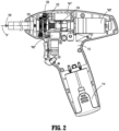
- a surgical instrument in accordance with an embodiment of the present disclosure, is generally designated as 10, and is in the form of a powered hand-held electromechanical surgical instrument configured for selective coupling thereto of a plurality of different surgical end effectors, for example, the surgical end effector 200 of FIGS. 1 and 10 .
- the end effector 200 is configured for actuation and manipulation by the powered hand-held electromechanical surgical instrument 10.
- the hand-held electromechanical surgical instrument 10 includes a handle assembly 100 and a shaft portion 102 extending distally from the handle assembly 100 configured for selective connection with a surgical attachment, such as, for example, the end effector 200 ( FIG. 10 ).
- the handle assembly 100 has a fire switch 162 configured and adapted to actuate the various functions of the end effector 200.
- the handle assembly 100 has an articulation switch 160 and a rotation switch 164 configured to respectively actuate an articulation of the end effector 200 (e.g., move the end effector 200 along a horizontal plane between a position coaxial with the shaft portion 102 and multiple positions out of alignment with the shaft portion 102) and rotate the end effector 200 (e.g., rotate the end effector 200 about a central longitudinal axis "X" defined by the shaft portion 102), as will be described in more detail herein.
- an articulation switch 160 and a rotation switch 164 configured to respectively actuate an articulation of the end effector 200 (e.g., move the end effector 200 along a horizontal plane between a position coaxial with the shaft portion 102 and multiple positions out of alignment with the shaft portion 102) and rotate the end effector 200 (e.g., rotate the end effector 200 about a central longitudinal axis "X" defined by the shaft portion 102), as will be described in more detail herein.
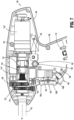
- the handle assembly 100 includes a handle housing 104 consisting of a body 106 and a handle portion 108 extending perpendicularly downward from the body 106.
- the body 106 of the handle housing 104 has a plurality of motors, for example, a first motor M1, a second motor M2, and a third motor M3, situated therein.
- the handle housing 104 further includes a motor controller printed circuit board 112 coupled to the plurality of motors M1-M3.
- the first motor M1, the second motor M2, and the third motor M3 are each electrically connected or wirelessly connected to the printed circuit board 112 and a battery pack 114 of the handle assembly 100.
- Each motor M1-M3 is controlled by a respective motor controller or processor (not explicitly shown).
- Rotation of motor shafts by respective motors M1-M3 function to drive shafts and/or gear components of the handle assembly 100 in order to perform the various operations of the end effector 200 ( FIG. 10 ).
- the first motor M1 is configured to articulate the end effector 200 relative to the shaft portion 102
- the second motor M2 is configured to move jaw members 206, 208 ( FIG. 10 ) of the end effector 200 relative to one another and/or to fire staples from the end effector 200
- the third motor M3 is configured to rotate the end effector 200 about the longitudinal axis "X" defined by the shaft portion 102.
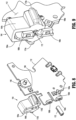
- the handle assembly 100 includes an articulation assembly 120 configured to effect the articulation of the end effector 200 ( FIG. 10 ).
- the articulation assembly 120 has a drive nut 122 operably coupled to the first motor M1 and an articulation shaft 124 operably coupled to the drive nut 122.
- the drive nut 122 is axially restrained and rotatably supported in the body 106 of the handle housing 104.
- the drive nut 122 has a geared outer surface 126 and a threaded inner surface (not explicitly shown).
- the geared outer surface 126 of the drive nut 122 interfaces with a spur gear 128 fixed to a drive shaft of the first motor M1, such that rotation of the spur gear 128, via an activation of the first motor M1, causes the drive nut 122 to rotate.
- the drive nut 122 is disposed about a proximal end portion 124a of the articulation shaft 124, with the threaded inner surface of the drive nut 122 threadedly coupled to a threaded outer surface 130 of the proximal end portion 124a of the articulation shaft 124.
- a rotation of the drive nut 122 drives the axial movement of the articulation shaft 124 in either a proximal or distal direction depending on the direction of rotation of the drive nut 122.
- the articulation shaft 124 is laterally offset from the central longitudinal axis "X" defined by the shaft portion 102 and extends distally from within the handle housing 104 and through the shaft portion 102.
- the articulation shaft 124 has a distal end portion 124b defining a hooked feature 132 configured to interface with a proximal end of an articulation link 203 of the end effector 200 ( FIG. 10 ) to drive the articulation of a tool assembly 204 of the end effector 200 relative to a proximal body portion 202 of the end effector 200.
- the distal end portion 124b of the articulation shaft 124 may have any suitable coupling arrangement with the end effector 200 to effect an articulation of the end effector 200, such as a rack and pinion connection, as shown and described in U.S. Patent Application Publication No. 2016/0324514, filed on May 6, 2015 .
- the handle assembly 100 further includes an articulation monitoring system 140 configured to sense the articulation position of the end effector 200 ( FIG. 10 ) relative to the shaft portion 102.
- the articulation monitoring system 140 may constantly determine the angle between a longitudinal axis defined by the end effector 200 and the longitudinal axis "X" defined by the shaft portion 102.
- the articulation monitoring system 140 includes an articulation block or slide 142, a rack 144, and a position sensor 146.
- the articulation block 142 of the articulation monitoring system 140 is axially fixed with the proximal end portion 124a of the articulation shaft 124, whereby the articulation block 142 linearly translates with the articulation shaft 124.
- the rack 144 of the articulation monitoring system 140 may be flexible and has an arcuate shape. In examples not forming part of the invention, the rack 144 may assume any suitable shape, such as, for example, linear.
- the rack 144 is slidably disposed between a pair of guides 148 formed with the handle housing 104 to allow for translation of the rack 144 along an arcuate path.
- the rack 144 has a distal end portion 150 secured to the articulation block 142, such that linear movement of the articulation block 142 drives a translation of the rack 144 along the arcuate path.
- Gear teeth of the rack 144 interface with a spur gear 152 of the position sensor 146 to rotate the spur gear 152 of the position sensor 146 as the articulation shaft 124 moves axially.
- the position sensor 146 is illustrated as a rotary potentiometer, however, it is contemplated that the position sensor 146 may be any suitable rotary or linear position sensor, such as, for example, a capacitive sensor, a magnetoresistive sensor, an eddy-current sensor, a hall-effect sensor, an optical sensor, or the like.
- the position sensor 146 is fixed within the handle housing 104 and is coupled to the rack 144.
- a sensed element in the position sensor 146 such as a wiper contact (not shown) moves relative to a sensing element in the position sensor 146, such as a resistive track (not shown), whereby the voltage between the wiper contact and the resistive track is monitored.
- the voltage determined by the position sensor 146 is proportional to the articulation angle of the end effector 200 ( FIG. 10 ) relative to the shaft portion 102, thus providing the surgical instrument 10 with a means for detecting the articulation position of the end effector 200 at all times.
- the articulation switch 160 of the handle assembly 100 is actuated in either a left or right direction to articulate the end effector 200 in a corresponding direction.
- moving the articulation switch 160 to the left may cause the printed circuit board 112 to transmit a signal to the first motor M1 to rotate its motor shaft and the attached spur gear 128 in a clockwise direction, thereby rotating the drive nut 122 of the articulation assembly 120 in a counter-clockwise direction.
- the proximal movement of the articulation shaft 124 retracts the articulation block 142 of the articulation monitoring system 140.
- the rack 144 is translated along its arcuate pathway to rotate the spur gear 152 of the position sensor 146. Due to the amount of rotation of the spur gear 152 being commensurate with the amount of articulation of the end effector 200, the position sensor 146 accurately determines the amount the end effector has been articulated, giving the clinician, the surgical instrument 10, and/or an associated robotic system the articulation position of the end effector 200.
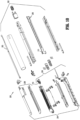
- the articulation switch 160 is swivelable relative to the handle portion 108 of the handle housing 104 in a left-right direction to ultimately effect an articulation of the end effector 200 ( FIG. 10 ) in the corresponding direction, by way of the mechanical linkages described above.
- the articulation switch 160 has a bifurcated proximal end 166 that straddles opposing sides of the printed circuit board 112.
- the bifurcated proximal end 166 of the articulation switch 160 has a first finger that abuts a first contact switch 168a of the printed circuit board 112, and a second finger that abuts a second contact switch (not explicitly shown) of the printed circuit board 112.
- swiveling the articulation switch 160 towards the left activates the first contact switch 168a, which activates the first motor M1 to articulate the end effector 200 towards the left
- swiveling the articulation switch 160 towards the right activates the second contact switch, which activates the first motor M1 to articulate the end effector 200 towards the right.
- the fire switch 162 may be constructed as a toggle bar pivotably coupled to the handle portion 108 of the handle housing 104.
- the fire switch 162 extends perpendicularly relative to the longitudinal axis "X" of the shaft portion 102 and has a first end portion 162a and a second end portion 162b disposed on opposite sides of a pivot axis.
- the first end portion 162a abuts a third contact switch 168b of the printed circuit board 112, and the second end portion 162b abuts a fourth contact switch 168c of the printed circuit board 112.
- an application of a proximally-oriented force on the first end portion 162a of the fire switch 162 pivots the fire switch 162 in a first direction to activate the third contact switch 168b
- an application of a proximally-oriented force on the second end portion 162b of the fire switch 162 pivots the fire switch 162 in a second direction to activate the fourth contact switch 168c.
- An activation of the third contact switch 168b activates the second motor M1 to advance a firing rod 105 of the surgical instrument 10. Since the firing rod 105 is coupled to a drive assembly 209 of the end effector 200 (which includes a knife rod 211 and an actuation sled 213, FIG.
- advancement of the firing rod 105 advances the drive assembly 209 of the end effector 200, which both closes the jaw members 206, 208 of the end effector 200 and fires the end effector 200.
- An activation of the fourth contact switch 168c activates the second motor M1 to retract the firing rod 105, whereby the knife rod 211 of the drive assembly 209 of the end effector 200 retracts to open the jaw members 206, 208 of the end effector 200.
- the rotation switch 164 is disposed proximally of (e.g., behind) the fire switch 162 and above the articulation switch 160 and is configured to rotate about a pivot axis parallel with the rotation axis of the end effector 200.
- the rotation switch 164 straddles the printed circuit board 112 and has a first lateral arm 164a exposed on a first lateral side of the handle portion 108 of the handle housing 104, and a second lateral arm 164b exposed on a second lateral side of the handle portion 108 of the handle housing 104.
- the first and second lateral arms 164a, 164b of the rotation switch 164 have a respective tab 170a, 170b positioned and configured for actuation by a finger of a clinician.
- a pivot member 172 such as, for example, a pivot pin is keyed to the printed circuit board 112.
- the lateral arms 164a, 164b of the rotation switch 164 each define a rounded recess that together define a cylindrical passageway that accommodates the pivot member 172 therein.
- the lateral arms 164a, 164b of the rotation switch 164 are spaced from the respective opposing sides of the printed circuit board 112 to allow for rotation of the rotation switch 164 relative to and about the pivot member 172.
- the first lateral arm 164a of the rotation switch abuts a fifth contact switch (not explicitly shown) of the printed circuit board 112, and the second lateral arm 164b of the rotation switch 164 abuts a sixth contact switch 168d of the printed circuit board 112.
- An application of an upwardly-oriented force on the first lateral arm 164a of the rotation switch 164 or a downwardly-oriented force on the second lateral arm 164b of the rotation switch 164 rotates the rotation switch 164 about the pivot member 172 in a first direction to activate the sixth contact switch 168d, and an application of an upwardly-oriented force on the second lateral arm 164b of the rotation switch 164 or a downwardly-oriented force on the first lateral arm 164a of the rotation switch 164 rotates the rotation switch 164 about the pivot member 172 in a second direction to activate the fifth contact switch.
- An activation of the sixth contact switch 168d activates the third motor M3 to rotate, in sequence, a spur gear 174, the shaft portion 102, and the attached end effector 200 about the longitudinal axis "X" of the shaft portion 102 in the first direction
- an activation of the fifth contact switch activates the third motor M3 to rotate, in sequence, the spur gear 174, the shaft portion 102, and the attached end effector 200 about the longitudinal axis "X" of the shaft portion 102 in the second direction.
- a rotation of the shaft portion 102 may also cause the articulation shaft 124 to rotate relative to the drive nut 122, thereby inadvertently driving an articulation of the end effector 200.
- the processor may be configured to simultaneously activate the first motor M1 when the rotation switch 164 is actuated. In this way, the first motor M1 causes the drive nut 122 of the articulation assembly 120 to rotate in the same rotational direction as the shaft portion 102 to prevent relative rotation between the articulation shaft 124 and the drive nut 122.
- the first motor M1 ensuring that the drive nut 122 rotates with the articulation shaft 124 about the longitudinal axis "X" of the shaft portion 102, unintentional articulation of the end effector 200 may be avoided.
- the switches 160, 162, 164 of the handle assembly 100 may be assigned to actuate various functions to be carried out by various surgical end effectors. It is contemplated that the switches 160, 162, 164 can be variously configured, such as, for example, as switches, rockers, flaps, latches, levers, dials, buttons, or touch screens.
- the handle assembly 100 may further include a safety switch 180 constructed as an elongated bar extending transversely through the body 106 of the handle housing 104.
- the safety switch 180 has opposing end portions 182 ( FIG. 7 ), 184 ( FIG. 5 ) exposed from an outer surface of the handle housing 104 to allow a clinician to slide the safety switch 180 between a firing-disabled position and a firing-enabled position.
- the safety switch 180 In the firing-disabled position, the safety switch 180 one of contacts or disengages a contact switch 186 on the printed circuit board 112, whereby the processor is signaled to prevent an activation of the second motor M2 notwithstanding an actuation of the fire switch 162.
- the safety switch 180 contacts or disengages the contact switch 186, whereby the processor is signaled to allow an activation of the second motor M2 upon actuating the fire switch 162. It is contemplated that the safety switch 180 may be illuminated when in the firing-enabled position to give a clinician a visual indication that the safety is off and the surgical instrument 10 is ready for firing.
- the end effector 200 is configured to be coupled to a distal end of the shaft portion 102 of the surgical instrument 10.
- the end effector 200 includes a proximal body portion 202 and a tool assembly 204.
- the proximal body portion 202 is releasably attached to the distal end the handle portion 102 and the tool assembly 204 is pivotally attached to a distal end of the proximal body portion 202 of the end effector 200.
- the proximal body portion 202 is configured to articulate relative to the distal end of the shaft portion 102 via longitudinal translation of the articulation link 203, as described above.
- the tool assembly 204 includes an anvil assembly 206 and a cartridge assembly 208.
- the cartridge assembly 208 is pivotal in relation to the anvil assembly 206 and is movable between an open or unclamped position and a closed or clamped position for insertion through a cannula of a trocar.
- any of the components described herein may be fabricated from either metals, plastics, resins, composites or the like taking into consideration strength, durability, wearability, weight, resistance to corrosion, ease of manufacturing, cost of manufacturing, and the like.
Landscapes
- Health & Medical Sciences (AREA)
- Life Sciences & Earth Sciences (AREA)
- Surgery (AREA)
- Molecular Biology (AREA)
- General Health & Medical Sciences (AREA)
- Biomedical Technology (AREA)
- Heart & Thoracic Surgery (AREA)
- Medical Informatics (AREA)
- Nuclear Medicine, Radiotherapy & Molecular Imaging (AREA)
- Animal Behavior & Ethology (AREA)
- Engineering & Computer Science (AREA)
- Public Health (AREA)
- Veterinary Medicine (AREA)
- Ophthalmology & Optometry (AREA)
- Oral & Maxillofacial Surgery (AREA)
- Pathology (AREA)
- Surgical Instruments (AREA)
Claims (8)
- In der Hand gehaltenes chirurgisches Instrument (10), umfassend:ein Griffgehäuse (104),einen in dem Griffgehäuse angeordneten ersten Motor (M1),einen sich distal von dem Griffgehäuse erstreckenden Schaftabschnitt (102),eine Anlenkachse (124), die an den ersten Motor wirkgekoppelt und in dem Schaftabschnitt angeordnet ist, wobei die Anlenkachse dazu ausgestaltet ist, sich axial in dem Schaftabschnitt zu bewegen, um einen Endeffektor (200) anzulenken,einen Positionssensor (146), der der Anlenkachse zugeordnet ist, wobei der Positionssensor zur Bestimmung einer Anlenkposition der Anlenkachse ausgestaltet ist, undeine Zahnstange (144), die zwischen der Anlenkachse und dem Positionssensor wirkgekoppelt ist,dadurch gekennzeichnet, dassdie Zahnstange bogenförmig ist und als Reaktion auf eine axiale Bewegung der Anlenkachse entlang einer bogenförmigen Bahn translatiert, um den Positionssensor zu bewegen.
- In der Hand gehaltenes chirurgisches Instrument nach Anspruch 1, wobei der Positionssensor ein drehbares Zahnrad (152) hat, das mit der Zahnstange koppelt, so dass das drehbare Zahnrad durch die Translation der Zahnstange gedreht wird.
- In der Hand gehaltenes chirurgisches Instrument nach Anspruch 2, wobei der Positionssensor ein Drehpotentiometer ist.
- In der Hand gehaltenes chirurgisches Instrument nach Anspruch 1, ferner umfassend einen Anlenkblock (142), der mit der Anlenkachse und der Zahnstange befestigt ist, wobei der Anlenkblock die axiale Bewegung der Anlenkachse an die Zahnstange überträgt.
- In der Hand gehaltenes chirurgisches Instrument nach einem der Ansprüche 1, 2 oder 4, ferner umfassend eine Antriebsmutter (122), die an den ersten Motor wirkgekoppelt und als Reaktion auf eine Betätigung des ersten Motors drehbar ist, wobei die Antriebsmutter um einen proximalen Endabschnitt (124a) der Anlenkachse angeordnet und gewindemäßig daran gekoppelt ist, so dass eine Drehung der Antriebsmutter zu der axialen Bewegung der Anlenkachse führt, und/oder wobei der Positionssensor aus der aus einem Potentiomenter, einem kapazitiven Sensor, einem magnetoresistiven Sensor, einem Wirbelstromsensor, einem Hall-Effekt-Sensor und einem optischen Sensor bestehenden Gruppe ausgewählt ist.
- In der Hand gehaltenes chirurgisches Instrument nach einem der vorhergehenden Ansprüche, ferner umfassend einen Anlenkschalter (160), der schwenkbar an das Griffgehäuse gekoppelt und an den ersten Motor wirkgekoppelt ist, wobei der erste Motor durch eine Betätigung des Anlenkschalters aktiviert wird, und ferner umfassend einen Auslöseschalter (162), der an einer oberhalb des Anlenkschalters liegenden Stelle schwenkbar an den Griffabschnitt gekoppelt ist, wobei der Auslöseschalter zur Aktivierung eines Klemmens oder Auslösens des Endeffektors ausgestaltet ist.
- In der Hand gehaltenes chirurgisches Instrument nach Anspruch 6, ferner umfassend einen Drehschalter (164), der an einer proximal zu dem Auslöseschalter und oberhalb des Anlenkschalters liegenden Stelle an das Griffgehäuse drehgekoppelt ist, wobei der Drehschalter zur Aktivierung der Drehung des Endeffektors ausgestaltet ist, vorzugsweise ferner umfassend:einen an den Auslöseschalter wirkgekoppelten zweiten Motor (M2) undeinen an den Drehschalter wirkgekoppelten dritten Motor (M3).
- In der Hand gehaltenes chirurgisches Instrument nach Anspruch 7, ferner umfassend eine in dem Griffgehäuse angeordnete Leiterplatte (112), wobei der Anlenkschalter, der Auslöseschalter und der Drehschalter in elektrischer Verbindung mit der Leiterplatte stehen, vorzugsweise ferner umfassend ein auf die Leiterplatte aufgekeiltes Drehzapfenglied (172), wobei der Drehschalter an das Drehzapfenglied drehgekoppelt ist.
Applications Claiming Priority (2)
| Application Number | Priority Date | Filing Date | Title |
|---|---|---|---|
| US201862695883P | 2018-07-10 | 2018-07-10 | |
| US16/441,750 US11272948B2 (en) | 2018-07-10 | 2019-06-14 | Hand-held surgical instruments |
Publications (3)
| Publication Number | Publication Date |
|---|---|
| EP3593732A2 EP3593732A2 (de) | 2020-01-15 |
| EP3593732A3 EP3593732A3 (de) | 2020-03-04 |
| EP3593732B1 true EP3593732B1 (de) | 2023-12-27 |
Family
ID=67220688
Family Applications (1)
| Application Number | Title | Priority Date | Filing Date |
|---|---|---|---|
| EP19185132.8A Active EP3593732B1 (de) | 2018-07-10 | 2019-07-09 | Handhaltbare chirurgische instrumente |
Country Status (5)
| Country | Link |
|---|---|
| US (1) | US11272948B2 (de) |
| EP (1) | EP3593732B1 (de) |
| JP (1) | JP7386632B2 (de) |
| CN (1) | CN110693555B (de) |
| AU (1) | AU2019204308A1 (de) |
Families Citing this family (50)
| Publication number | Priority date | Publication date | Assignee | Title |
|---|---|---|---|---|
| US9060770B2 (en) | 2003-05-20 | 2015-06-23 | Ethicon Endo-Surgery, Inc. | Robotically-driven surgical instrument with E-beam driver |
| US20070084897A1 (en) | 2003-05-20 | 2007-04-19 | Shelton Frederick E Iv | Articulating surgical stapling instrument incorporating a two-piece e-beam firing mechanism |
| US11896225B2 (en) | 2004-07-28 | 2024-02-13 | Cilag Gmbh International | Staple cartridge comprising a pan |
| US7669746B2 (en) | 2005-08-31 | 2010-03-02 | Ethicon Endo-Surgery, Inc. | Staple cartridges for forming staples having differing formed staple heights |
| US11246590B2 (en) | 2005-08-31 | 2022-02-15 | Cilag Gmbh International | Staple cartridge including staple drivers having different unfired heights |
| US8186555B2 (en) | 2006-01-31 | 2012-05-29 | Ethicon Endo-Surgery, Inc. | Motor-driven surgical cutting and fastening instrument with mechanical closure system |
| US11793518B2 (en) | 2006-01-31 | 2023-10-24 | Cilag Gmbh International | Powered surgical instruments with firing system lockout arrangements |
| US7845537B2 (en) | 2006-01-31 | 2010-12-07 | Ethicon Endo-Surgery, Inc. | Surgical instrument having recording capabilities |
| US8708213B2 (en) | 2006-01-31 | 2014-04-29 | Ethicon Endo-Surgery, Inc. | Surgical instrument having a feedback system |
| US11980366B2 (en) | 2006-10-03 | 2024-05-14 | Cilag Gmbh International | Surgical instrument |
| US8684253B2 (en) | 2007-01-10 | 2014-04-01 | Ethicon Endo-Surgery, Inc. | Surgical instrument with wireless communication between a control unit of a robotic system and remote sensor |
| US8931682B2 (en) | 2007-06-04 | 2015-01-13 | Ethicon Endo-Surgery, Inc. | Robotically-controlled shaft based rotary drive systems for surgical instruments |
| US11672531B2 (en) | 2007-06-04 | 2023-06-13 | Cilag Gmbh International | Rotary drive systems for surgical instruments |
| US11849941B2 (en) | 2007-06-29 | 2023-12-26 | Cilag Gmbh International | Staple cartridge having staple cavities extending at a transverse angle relative to a longitudinal cartridge axis |
| US11986183B2 (en) | 2008-02-14 | 2024-05-21 | Cilag Gmbh International | Surgical cutting and fastening instrument comprising a plurality of sensors to measure an electrical parameter |
| US9005230B2 (en) | 2008-09-23 | 2015-04-14 | Ethicon Endo-Surgery, Inc. | Motorized surgical instrument |
| US11849952B2 (en) | 2010-09-30 | 2023-12-26 | Cilag Gmbh International | Staple cartridge comprising staples positioned within a compressible portion thereof |
| US10945731B2 (en) | 2010-09-30 | 2021-03-16 | Ethicon Llc | Tissue thickness compensator comprising controlled release and expansion |
| US11812965B2 (en) | 2010-09-30 | 2023-11-14 | Cilag Gmbh International | Layer of material for a surgical end effector |
| US10405854B2 (en) | 2010-09-30 | 2019-09-10 | Ethicon Llc | Surgical stapling cartridge with layer retention features |
| US9386988B2 (en) | 2010-09-30 | 2016-07-12 | Ethicon End-Surgery, LLC | Retainer assembly including a tissue thickness compensator |
| US9629814B2 (en) | 2010-09-30 | 2017-04-25 | Ethicon Endo-Surgery, Llc | Tissue thickness compensator configured to redistribute compressive forces |
| US9072535B2 (en) | 2011-05-27 | 2015-07-07 | Ethicon Endo-Surgery, Inc. | Surgical stapling instruments with rotatable staple deployment arrangements |
| MX358135B (es) | 2012-03-28 | 2018-08-06 | Ethicon Endo Surgery Inc | Compensador de grosor de tejido que comprende una pluralidad de capas. |
| BR112014024098B1 (pt) | 2012-03-28 | 2021-05-25 | Ethicon Endo-Surgery, Inc. | cartucho de grampos |
| US20140001231A1 (en) | 2012-06-28 | 2014-01-02 | Ethicon Endo-Surgery, Inc. | Firing system lockout arrangements for surgical instruments |
| MX368026B (es) | 2013-03-01 | 2019-09-12 | Ethicon Endo Surgery Inc | Instrumento quirúrgico articulable con vías conductoras para la comunicación de la señal. |
| BR112016023807B1 (pt) | 2014-04-16 | 2022-07-12 | Ethicon Endo-Surgery, Llc | Conjunto de cartucho de prendedores para uso com um instrumento cirúrgico |
| CN106456158B (zh) | 2014-04-16 | 2019-02-05 | 伊西康内外科有限责任公司 | 包括非一致紧固件的紧固件仓 |
| US20150297222A1 (en) | 2014-04-16 | 2015-10-22 | Ethicon Endo-Surgery, Inc. | Fastener cartridges including extensions having different configurations |
| CN106456176B (zh) | 2014-04-16 | 2019-06-28 | 伊西康内外科有限责任公司 | 包括具有不同构型的延伸部的紧固件仓 |
| US9924944B2 (en) | 2014-10-16 | 2018-03-27 | Ethicon Llc | Staple cartridge comprising an adjunct material |
| US10390825B2 (en) | 2015-03-31 | 2019-08-27 | Ethicon Llc | Surgical instrument with progressive rotary drive systems |
| US10105139B2 (en) | 2015-09-23 | 2018-10-23 | Ethicon Llc | Surgical stapler having downstream current-based motor control |
| US11890015B2 (en) | 2015-09-30 | 2024-02-06 | Cilag Gmbh International | Compressible adjunct with crossing spacer fibers |
| US10357247B2 (en) | 2016-04-15 | 2019-07-23 | Ethicon Llc | Surgical instrument with multiple program responses during a firing motion |
| US20170296173A1 (en) | 2016-04-18 | 2017-10-19 | Ethicon Endo-Surgery, Llc | Method for operating a surgical instrument |
| US20180168625A1 (en) | 2016-12-21 | 2018-06-21 | Ethicon Endo-Surgery, Llc | Surgical stapling instruments with smart staple cartridges |
| JP7010956B2 (ja) | 2016-12-21 | 2022-01-26 | エシコン エルエルシー | 組織をステープル留めする方法 |
| US10307170B2 (en) | 2017-06-20 | 2019-06-04 | Ethicon Llc | Method for closed loop control of motor velocity of a surgical stapling and cutting instrument |
| US10932772B2 (en) | 2017-06-29 | 2021-03-02 | Ethicon Llc | Methods for closed loop velocity control for robotic surgical instrument |
| US10842490B2 (en) | 2017-10-31 | 2020-11-24 | Ethicon Llc | Cartridge body design with force reduction based on firing completion |
| US10779826B2 (en) | 2017-12-15 | 2020-09-22 | Ethicon Llc | Methods of operating surgical end effectors |
| WO2021145437A1 (ja) | 2020-01-17 | 2021-07-22 | 日置電機株式会社 | 装置、測定装置、方法及び測定方法 |
| USD1013170S1 (en) | 2020-10-29 | 2024-01-30 | Cilag Gmbh International | Surgical instrument assembly |
| US11826012B2 (en) | 2021-03-22 | 2023-11-28 | Cilag Gmbh International | Stapling instrument comprising a pulsed motor-driven firing rack |
| US11806011B2 (en) | 2021-03-22 | 2023-11-07 | Cilag Gmbh International | Stapling instrument comprising tissue compression systems |
| US11826042B2 (en) | 2021-03-22 | 2023-11-28 | Cilag Gmbh International | Surgical instrument comprising a firing drive including a selectable leverage mechanism |
| US11918217B2 (en) | 2021-05-28 | 2024-03-05 | Cilag Gmbh International | Stapling instrument comprising a staple cartridge insertion stop |
| US11937816B2 (en) | 2021-10-28 | 2024-03-26 | Cilag Gmbh International | Electrical lead arrangements for surgical instruments |
Family Cites Families (68)
| Publication number | Priority date | Publication date | Assignee | Title |
|---|---|---|---|---|
| GB1579715A (en) | 1977-03-12 | 1980-11-26 | Omron Tateisi Electronics Co | Contacless switch and method of making the same |
| US4803362A (en) | 1987-10-27 | 1989-02-07 | Labworks, Inc. | Electro-optically activated switch with tactile feedback |
| US5272383A (en) | 1989-04-21 | 1993-12-21 | Shinkoh Electric Co., Ltd. | Method and apparatus for preventing erroneous operation in non-contact push-button switch |
| JPH06297379A (ja) * | 1993-04-16 | 1994-10-25 | Fanuc Ltd | 産業用ロボットのオーバートラベル検出装置 |
| US5747953A (en) | 1996-03-29 | 1998-05-05 | Stryker Corporation | Cordless, battery operated surical tool |
| US6025683A (en) | 1998-12-23 | 2000-02-15 | Stryker Corporation | Motor control circuit for regulating a D.C. motor |
| US6517565B1 (en) | 1999-06-02 | 2003-02-11 | Power Medical Interventions, Inc. | Carriage assembly for controlling a steering wire steering mechanism within a flexible shaft |
| KR100651963B1 (ko) | 2000-09-08 | 2006-11-30 | 엘지전자 주식회사 | 무접점 로터리 스위치 어셈블리 |
| US6960894B2 (en) | 2002-08-01 | 2005-11-01 | Stryker Corporation | Cordless, powered surgical tool |
| CA2500832C (en) * | 2002-10-04 | 2011-03-22 | Tyco Healthcare Group, Lp | Tool assembly for a surgical stapling device |
| CA2724284C (en) * | 2003-06-17 | 2013-02-26 | Tyco Healthcare Group Lp | Surgical stapling device |
| US7914543B2 (en) * | 2003-10-14 | 2011-03-29 | Satiety, Inc. | Single fold device for tissue fixation |
| US8968276B2 (en) | 2007-09-21 | 2015-03-03 | Covidien Lp | Hand held surgical handle assembly, surgical adapters for use between surgical handle assembly and surgical end effectors, and methods of use |
| US20090090763A1 (en) * | 2007-10-05 | 2009-04-09 | Tyco Healthcare Group Lp | Powered surgical stapling device |
| US9055943B2 (en) | 2007-09-21 | 2015-06-16 | Covidien Lp | Hand held surgical handle assembly, surgical adapters for use between surgical handle assembly and surgical end effectors, and methods of use |
| US10588629B2 (en) | 2009-11-20 | 2020-03-17 | Covidien Lp | Surgical console and hand-held surgical device |
| US9113880B2 (en) * | 2007-10-05 | 2015-08-25 | Covidien Lp | Internal backbone structural chassis for a surgical device |
| US7638958B2 (en) | 2005-06-28 | 2009-12-29 | Stryker Corporation | Powered surgical tool with control module that contains a sensor for remotely monitoring the tool power generating unit |
| US8800838B2 (en) * | 2005-08-31 | 2014-08-12 | Ethicon Endo-Surgery, Inc. | Robotically-controlled cable-based surgical end effectors |
| US8684253B2 (en) * | 2007-01-10 | 2014-04-01 | Ethicon Endo-Surgery, Inc. | Surgical instrument with wireless communication between a control unit of a robotic system and remote sensor |
| KR200442312Y1 (ko) | 2007-01-19 | 2008-10-29 | 우진전장 주식회사 | 비접촉식 광스위치가 구비된 엘리베이터 버튼 |
| WO2008147415A1 (en) | 2007-05-31 | 2008-12-04 | Cox Raleigh L | An optical switch |
| US9539061B2 (en) | 2007-07-25 | 2017-01-10 | Karl Storz Gmbh & Co. Kg | Medical manipulator and welding method |
| CN101801283B (zh) | 2007-09-21 | 2012-07-18 | Tyco医疗健康集团 | 手术器械 |
| US10498269B2 (en) | 2007-10-05 | 2019-12-03 | Covidien Lp | Powered surgical stapling device |
| US10779818B2 (en) * | 2007-10-05 | 2020-09-22 | Covidien Lp | Powered surgical stapling device |
| US8960520B2 (en) | 2007-10-05 | 2015-02-24 | Covidien Lp | Method and apparatus for determining parameters of linear motion in a surgical instrument |
| US8105233B2 (en) * | 2007-10-24 | 2012-01-31 | Tarek Ahmed Nabil Abou El Kheir | Endoscopic system and method for therapeutic applications and obtaining 3-dimensional human vision simulated imaging with real dynamic convergence |
| US7922063B2 (en) * | 2007-10-31 | 2011-04-12 | Tyco Healthcare Group, Lp | Powered surgical instrument |
| CN101227187A (zh) | 2008-02-04 | 2008-07-23 | 黄国芳 | 一种应用在汽车上的无触点开关 |
| US10368838B2 (en) * | 2008-03-31 | 2019-08-06 | Intuitive Surgical Operations, Inc. | Surgical tools for laser marking and laser cutting |
| US9386983B2 (en) * | 2008-09-23 | 2016-07-12 | Ethicon Endo-Surgery, Llc | Robotically-controlled motorized surgical instrument |
| US20100171026A1 (en) | 2009-01-07 | 2010-07-08 | Anywire Corporation | On/off switch |
| US8393516B2 (en) * | 2009-02-26 | 2013-03-12 | Covidien Lp | Surgical stapling apparatus with curved cartridge and anvil assemblies |
| US8453906B2 (en) * | 2010-07-14 | 2013-06-04 | Ethicon Endo-Surgery, Inc. | Surgical instruments with electrodes |
| CN102858225B (zh) | 2010-07-29 | 2015-04-22 | 奥林巴斯医疗株式会社 | 医疗器具保持装置 |
| US8480703B2 (en) | 2010-11-19 | 2013-07-09 | Covidien Lp | Surgical device |
| EP2691213B2 (de) | 2011-03-31 | 2019-12-04 | Ingersoll-Rand Company | Vorwärts/rückwärts-schaltvorrichtung für elektrowerkzeuge |
| US10542978B2 (en) * | 2011-05-27 | 2020-01-28 | Covidien Lp | Method of internally potting or sealing a handheld medical device |
| US8894647B2 (en) | 2012-01-13 | 2014-11-25 | Covidien Lp | System and method for performing surgical procedures with a reusable instrument module |
| US10080563B2 (en) | 2012-06-01 | 2018-09-25 | Covidien Lp | Loading unit detection assembly and surgical device for use therewith |
| US9597104B2 (en) | 2012-06-01 | 2017-03-21 | Covidien Lp | Handheld surgical handle assembly, surgical adapters for use between surgical handle assembly and surgical end effectors, and methods of use |
| US9868198B2 (en) | 2012-06-01 | 2018-01-16 | Covidien Lp | Hand held surgical handle assembly, surgical adapters for use between surgical handle assembly and surgical loading units, and methods of use |
| US9955965B2 (en) | 2012-07-09 | 2018-05-01 | Covidien Lp | Switch block control assembly of a medical device |
| US9700310B2 (en) * | 2013-08-23 | 2017-07-11 | Ethicon Llc | Firing member retraction devices for powered surgical instruments |
| US9066710B2 (en) | 2012-10-19 | 2015-06-30 | St. Jude Medical, Cardiology Division, Inc. | Apparatus and method for heart valve repair |
| US9782187B2 (en) | 2013-01-18 | 2017-10-10 | Covidien Lp | Adapter load button lockout |
| CN203014768U (zh) | 2013-01-24 | 2013-06-19 | 衢州昀睿工业设计有限公司 | 一种无触点倒顺按钮开关 |
| US9468438B2 (en) | 2013-03-01 | 2016-10-18 | Eticon Endo-Surgery, LLC | Sensor straightened end effector during removal through trocar |
| US9351726B2 (en) | 2013-03-14 | 2016-05-31 | Ethicon Endo-Surgery, Llc | Articulation control system for articulatable surgical instruments |
| US9775610B2 (en) | 2013-04-09 | 2017-10-03 | Covidien Lp | Apparatus for endoscopic procedures |
| US9700318B2 (en) | 2013-04-09 | 2017-07-11 | Covidien Lp | Apparatus for endoscopic procedures |
| US9801626B2 (en) * | 2013-04-16 | 2017-10-31 | Ethicon Llc | Modular motor driven surgical instruments with alignment features for aligning rotary drive shafts with surgical end effector shafts |
| US9801646B2 (en) | 2013-05-30 | 2017-10-31 | Covidien Lp | Adapter load button decoupled from loading unit sensor |
| CN104224254B (zh) * | 2013-06-20 | 2016-03-30 | 瑞奇外科器械(中国)有限公司 | 外科手术器械及其驱动装置 |
| US9351728B2 (en) * | 2013-06-28 | 2016-05-31 | Covidien Lp | Articulating apparatus for endoscopic procedures |
| US9502192B2 (en) | 2014-02-14 | 2016-11-22 | Covidien Lp | Surgical instruments with non-contact switch assemblies |
| US20150374372A1 (en) | 2014-06-26 | 2015-12-31 | Covidien Lp | Hand held surgical handle assembly, surgical adapters for use between surgical handle assembly and surgical end effectors, and methods of use |
| US20160066913A1 (en) * | 2014-09-05 | 2016-03-10 | Ethicon Endo-Surgery, Inc. | Local display of tissue parameter stabilization |
| CN106999202B (zh) * | 2014-09-25 | 2019-11-15 | 柯惠有限合伙公司 | 可延伸长度的外科器械 |
| US9991069B2 (en) | 2014-10-22 | 2018-06-05 | Covidien Lp | Surgical instruments and switch assemblies thereof |
| US10314638B2 (en) * | 2015-04-07 | 2019-06-11 | Ethicon Llc | Articulating radio frequency (RF) tissue seal with articulating state sensing |
| US10039532B2 (en) * | 2015-05-06 | 2018-08-07 | Covidien Lp | Surgical instrument with articulation assembly |
| US11229471B2 (en) * | 2016-01-15 | 2022-01-25 | Cilag Gmbh International | Modular battery powered handheld surgical instrument with selective application of energy based on tissue characterization |
| US10245030B2 (en) * | 2016-02-09 | 2019-04-02 | Ethicon Llc | Surgical instruments with tensioning arrangements for cable driven articulation systems |
| US11484310B2 (en) * | 2017-06-28 | 2022-11-01 | Cilag Gmbh International | Surgical instrument comprising a shaft including a closure tube profile |
| US20190201034A1 (en) * | 2017-12-28 | 2019-07-04 | Ethicon Llc | Powered stapling device configured to adjust force, advancement speed, and overall stroke of cutting member based on sensed parameter of firing or clamping |
| JP7423538B2 (ja) * | 2018-02-27 | 2024-01-29 | アプライド メディカル リソーシーズ コーポレイション | 電動ハンドルを有する外科用ステープラ |
-
2019
- 2019-06-14 US US16/441,750 patent/US11272948B2/en active Active
- 2019-06-19 AU AU2019204308A patent/AU2019204308A1/en not_active Abandoned
- 2019-07-03 JP JP2019124479A patent/JP7386632B2/ja active Active
- 2019-07-04 CN CN201910599389.9A patent/CN110693555B/zh active Active
- 2019-07-09 EP EP19185132.8A patent/EP3593732B1/de active Active
Also Published As
| Publication number | Publication date |
|---|---|
| JP7386632B2 (ja) | 2023-11-27 |
| CN110693555B (zh) | 2024-04-02 |
| US20200015836A1 (en) | 2020-01-16 |
| US11272948B2 (en) | 2022-03-15 |
| EP3593732A3 (de) | 2020-03-04 |
| CN110693555A (zh) | 2020-01-17 |
| EP3593732A2 (de) | 2020-01-15 |
| AU2019204308A1 (en) | 2020-01-30 |
| JP2020006174A (ja) | 2020-01-16 |
Similar Documents
| Publication | Publication Date | Title |
|---|---|---|
| EP3593732B1 (de) | Handhaltbare chirurgische instrumente | |
| US20190076135A1 (en) | System and method for non-contact electronic articulation sensing | |
| US11751874B2 (en) | Powered surgical devices including strain gauges incorporated into flex circuits | |
| US10446342B2 (en) | Surgical instruments and switch assemblies thereof | |
| US20200330172A1 (en) | Methods, Systems, and Devices Relating to Force Control Surgical Systems | |
| CN110868953B (zh) | 用于外科机器人的平移器械接口和包括该接口的外科机器人系统 | |
| US10695063B2 (en) | Surgical cutting and fastening instrument with apparatus for determining cartridge and firing motion status | |
| US9867617B2 (en) | Articulating powered surgical instruments | |
| US9010611B2 (en) | End effector identification by mechanical features | |
| EP3245957B1 (de) | Chirurgische vorrichtung | |
| CN111479519A (zh) | 具有用于定位与其联接的适配器的部件的改善的马达控制布置的手持式机电外科器械 | |
| US10968981B2 (en) | Electromechanical surgical devices with single motor drives and adapter assemblies therfor | |
| US20230182303A1 (en) | Surgical robotic system instrument engagement and failure detection | |
| US11540827B2 (en) | Hand-held electromechanical surgical instruments | |
| CN110772325A (zh) | 手柄及主操作台 | |
| JP6177477B2 (ja) | マニピュレータシステム | |
| CN210130920U (zh) | 手柄及主操作台 | |
| US20220370165A1 (en) | Console for controlling a robotic manipulator | |
| CN114509195A (zh) | 动力外科手术设备中马达扭矩的非接触式力测量 |
Legal Events
| Date | Code | Title | Description |
|---|---|---|---|
| PUAI | Public reference made under article 153(3) epc to a published international application that has entered the european phase |
Free format text: ORIGINAL CODE: 0009012 |
|
| STAA | Information on the status of an ep patent application or granted ep patent |
Free format text: STATUS: THE APPLICATION HAS BEEN PUBLISHED |
|
| AK | Designated contracting states |
Kind code of ref document: A2 Designated state(s): AL AT BE BG CH CY CZ DE DK EE ES FI FR GB GR HR HU IE IS IT LI LT LU LV MC MK MT NL NO PL PT RO RS SE SI SK SM TR |
|
| AX | Request for extension of the european patent |
Extension state: BA ME |
|
| PUAL | Search report despatched |
Free format text: ORIGINAL CODE: 0009013 |
|
| AK | Designated contracting states |
Kind code of ref document: A3 Designated state(s): AL AT BE BG CH CY CZ DE DK EE ES FI FR GB GR HR HU IE IS IT LI LT LU LV MC MK MT NL NO PL PT RO RS SE SI SK SM TR |
|
| AX | Request for extension of the european patent |
Extension state: BA ME |
|
| RIC1 | Information provided on ipc code assigned before grant |
Ipc: A61B 17/072 20060101AFI20200128BHEP |
|
| STAA | Information on the status of an ep patent application or granted ep patent |
Free format text: STATUS: REQUEST FOR EXAMINATION WAS MADE |
|
| 17P | Request for examination filed |
Effective date: 20200902 |
|
| RBV | Designated contracting states (corrected) |
Designated state(s): AL AT BE BG CH CY CZ DE DK EE ES FI FR GB GR HR HU IE IS IT LI LT LU LV MC MK MT NL NO PL PT RO RS SE SI SK SM TR |
|
| STAA | Information on the status of an ep patent application or granted ep patent |
Free format text: STATUS: EXAMINATION IS IN PROGRESS |
|
| 17Q | First examination report despatched |
Effective date: 20220607 |
|
| GRAP | Despatch of communication of intention to grant a patent |
Free format text: ORIGINAL CODE: EPIDOSNIGR1 |
|
| STAA | Information on the status of an ep patent application or granted ep patent |
Free format text: STATUS: GRANT OF PATENT IS INTENDED |
|
| INTG | Intention to grant announced |
Effective date: 20230724 |
|
| GRAS | Grant fee paid |
Free format text: ORIGINAL CODE: EPIDOSNIGR3 |
|
| GRAA | (expected) grant |
Free format text: ORIGINAL CODE: 0009210 |
|
| STAA | Information on the status of an ep patent application or granted ep patent |
Free format text: STATUS: THE PATENT HAS BEEN GRANTED |
|
| AK | Designated contracting states |
Kind code of ref document: B1 Designated state(s): AL AT BE BG CH CY CZ DE DK EE ES FI FR GB GR HR HU IE IS IT LI LT LU LV MC MK MT NL NO PL PT RO RS SE SI SK SM TR |
|
| REG | Reference to a national code |
Ref country code: GB Ref legal event code: FG4D |
|
| REG | Reference to a national code |
Ref country code: CH Ref legal event code: EP |
|
| REG | Reference to a national code |
Ref country code: DE Ref legal event code: R096 Ref document number: 602019043875 Country of ref document: DE |
|
| REG | Reference to a national code |
Ref country code: IE Ref legal event code: FG4D |
|
| PG25 | Lapsed in a contracting state [announced via postgrant information from national office to epo] |
Ref country code: GR Free format text: LAPSE BECAUSE OF FAILURE TO SUBMIT A TRANSLATION OF THE DESCRIPTION OR TO PAY THE FEE WITHIN THE PRESCRIBED TIME-LIMIT Effective date: 20240328 |
|
| REG | Reference to a national code |
Ref country code: LT Ref legal event code: MG9D |
|
| PG25 | Lapsed in a contracting state [announced via postgrant information from national office to epo] |
Ref country code: LT Free format text: LAPSE BECAUSE OF FAILURE TO SUBMIT A TRANSLATION OF THE DESCRIPTION OR TO PAY THE FEE WITHIN THE PRESCRIBED TIME-LIMIT Effective date: 20231227 |
|
| PG25 | Lapsed in a contracting state [announced via postgrant information from national office to epo] |
Ref country code: ES Free format text: LAPSE BECAUSE OF FAILURE TO SUBMIT A TRANSLATION OF THE DESCRIPTION OR TO PAY THE FEE WITHIN THE PRESCRIBED TIME-LIMIT Effective date: 20231227 |
|
| PG25 | Lapsed in a contracting state [announced via postgrant information from national office to epo] |
Ref country code: LT Free format text: LAPSE BECAUSE OF FAILURE TO SUBMIT A TRANSLATION OF THE DESCRIPTION OR TO PAY THE FEE WITHIN THE PRESCRIBED TIME-LIMIT Effective date: 20231227 Ref country code: GR Free format text: LAPSE BECAUSE OF FAILURE TO SUBMIT A TRANSLATION OF THE DESCRIPTION OR TO PAY THE FEE WITHIN THE PRESCRIBED TIME-LIMIT Effective date: 20240328 Ref country code: FI Free format text: LAPSE BECAUSE OF FAILURE TO SUBMIT A TRANSLATION OF THE DESCRIPTION OR TO PAY THE FEE WITHIN THE PRESCRIBED TIME-LIMIT Effective date: 20231227 Ref country code: ES Free format text: LAPSE BECAUSE OF FAILURE TO SUBMIT A TRANSLATION OF THE DESCRIPTION OR TO PAY THE FEE WITHIN THE PRESCRIBED TIME-LIMIT Effective date: 20231227 Ref country code: BG Free format text: LAPSE BECAUSE OF FAILURE TO SUBMIT A TRANSLATION OF THE DESCRIPTION OR TO PAY THE FEE WITHIN THE PRESCRIBED TIME-LIMIT Effective date: 20240327 |
|
| REG | Reference to a national code |
Ref country code: NL Ref legal event code: MP Effective date: 20231227 |
|
| REG | Reference to a national code |
Ref country code: AT Ref legal event code: MK05 Ref document number: 1643790 Country of ref document: AT Kind code of ref document: T Effective date: 20231227 |
|
| PG25 | Lapsed in a contracting state [announced via postgrant information from national office to epo] |
Ref country code: NL Free format text: LAPSE BECAUSE OF FAILURE TO SUBMIT A TRANSLATION OF THE DESCRIPTION OR TO PAY THE FEE WITHIN THE PRESCRIBED TIME-LIMIT Effective date: 20231227 |