EP3593084B1 - Testing apparatus and method for testing a location-based application on a mobile device - Google Patents
Testing apparatus and method for testing a location-based application on a mobile device Download PDFInfo
- Publication number
- EP3593084B1 EP3593084B1 EP18716338.1A EP18716338A EP3593084B1 EP 3593084 B1 EP3593084 B1 EP 3593084B1 EP 18716338 A EP18716338 A EP 18716338A EP 3593084 B1 EP3593084 B1 EP 3593084B1
- Authority
- EP
- European Patent Office
- Prior art keywords
- platform
- recording device
- testing
- mirror
- support element
- Prior art date
- Legal status (The legal status is an assumption and is not a legal conclusion. Google has not performed a legal analysis and makes no representation as to the accuracy of the status listed.)
- Active
Links
Images
Classifications
-
- G—PHYSICS
- G06—COMPUTING OR CALCULATING; COUNTING
- G06F—ELECTRIC DIGITAL DATA PROCESSING
- G06F11/00—Error detection; Error correction; Monitoring
- G06F11/36—Prevention of errors by analysis, debugging or testing of software
- G06F11/3668—Testing of software
-
- G—PHYSICS
- G01—MEASURING; TESTING
- G01C—MEASURING DISTANCES, LEVELS OR BEARINGS; SURVEYING; NAVIGATION; GYROSCOPIC INSTRUMENTS; PHOTOGRAMMETRY OR VIDEOGRAMMETRY
- G01C25/00—Manufacturing, calibrating, cleaning, or repairing instruments or devices referred to in the other groups of this subclass
-
- G—PHYSICS
- G01—MEASURING; TESTING
- G01C—MEASURING DISTANCES, LEVELS OR BEARINGS; SURVEYING; NAVIGATION; GYROSCOPIC INSTRUMENTS; PHOTOGRAMMETRY OR VIDEOGRAMMETRY
- G01C21/00—Navigation; Navigational instruments not provided for in groups G01C1/00 - G01C19/00
- G01C21/20—Instruments for performing navigational calculations
- G01C21/206—Instruments for performing navigational calculations specially adapted for indoor navigation
-
- G—PHYSICS
- G06—COMPUTING OR CALCULATING; COUNTING
- G06F—ELECTRIC DIGITAL DATA PROCESSING
- G06F1/00—Details not covered by groups G06F3/00 - G06F13/00 and G06F21/00
- G06F1/16—Constructional details or arrangements
-
- G—PHYSICS
- G06—COMPUTING OR CALCULATING; COUNTING
- G06F—ELECTRIC DIGITAL DATA PROCESSING
- G06F11/00—Error detection; Error correction; Monitoring
- G06F11/36—Prevention of errors by analysis, debugging or testing of software
-
- H—ELECTRICITY
- H04—ELECTRIC COMMUNICATION TECHNIQUE
- H04M—TELEPHONIC COMMUNICATION
- H04M1/00—Substation equipment, e.g. for use by subscribers
- H04M1/24—Arrangements for testing
-
- G—PHYSICS
- G06—COMPUTING OR CALCULATING; COUNTING
- G06V—IMAGE OR VIDEO RECOGNITION OR UNDERSTANDING
- G06V10/00—Arrangements for image or video recognition or understanding
- G06V10/10—Image acquisition
- G06V10/12—Details of acquisition arrangements; Constructional details thereof
-
- H—ELECTRICITY
- H04—ELECTRIC COMMUNICATION TECHNIQUE
- H04W—WIRELESS COMMUNICATION NETWORKS
- H04W24/00—Supervisory, monitoring or testing arrangements
- H04W24/10—Scheduling measurement reports ; Arrangements for measurement reports
Definitions
- This invention relates to an apparatus and method for testing a location-based application on a mobile device. It is particularly, but not exclusively, concerned with testing location-based applications for use in large public spaces, such as airports, offices, shopping centres, event stadiums and rail or road stations.
- GPS Global Positioning System
- Wi-Fi triangulation or Bluetooth Low Energy Beacons
- airline operators may wish to provide passengers with a guide for navigating a particular airport, such a route or set of instructions for transferring between flights or locating a particular passenger lounge.
- Such services can require very accurate location information in order to provide the full level of desired functionality, and therefore testing of such applications at the ground level is critical to ensure proper functionality.
- application developers are typically not in a position to conduct such testing themselves, and consequently testing by local personnel is normally required at each site. This testing is often done on an ad-hoc basis with the local testing person carrying the mobile device around in their hand on the site and later reporting back on any identified problems. This can be inefficient and result in problems with the applications being missed or misreported.
- WO 2015/059553 A1 describes a phone holder for a mobile testing apparatus which can be adapted to securely hold a range of mobile phone models.
- the testing apparatus also comprises at least one camera, configured to monitor the position and/or orientation of a mobile phone supported by the phone holder, and a robot for operating the controls of the mobile phone.
- a mirror may be provided on the apparatus for providing the camera with a required perspective to better image the display of the mobile phone.
- US 9402016 B1 describes an apparatus for mounting a mobile device to a bicycle frame to permit video recording with a smartphone while riding.
- a testing apparatus for testing a location-based application on a mobile device, the apparatus comprising: a first platform having a support portion for supporting at least one test mobile device; and a support element spaced from the first platform and held in a fixed position relative to the first platform, the support element being configured to support a recording device and permit a camera lens on the recording device to view the support portion of the first platform.
- the apparatus comprises a mirror assembly comprising at least one mirror disposed between the first platform and the support element and orientated at an angle that is offset from the first platform, and being configured to reflect incoming light from a front side of the apparatus towards the camera lens on the recording device.
- the apparatus of the first aspect of the present invention advantageously provides an effective means for enabling a test person to test a location-based application on a mobile device in a test environment, whilst simultaneously recording the performance of the location-based application on the mobile device.
- This can enable the performance of the application to be analysed by any number of additional persons (in addition to the test person), irrespective of where those additional persons are located. Consequently, a person who is more qualified to understand the performance of the application, can view one or more images or videos captured by the recording device during testing, and analyse the performance of the application. This can improve the efficiency of the testing process, and potentially lead to better identification of problems in the applications.
- the image or videos captured by the recording device may be sent directly to the additional persons during testing (such as in the form of a live stream), or may be stored on a memory in the recording device, and later sent to the additional persons after testing.
- Arranging for at least one test mobile device to be supported by the first platform and the recording device to be supported by a support element that is spaced from the first platform and held in a fixed position relative to the first platform, can help to improve the quality of the video or image captured, since the at least one test mobile device is less likely to move relative to the recording device during testing. This can also reduce the burden on the test person, since they are no longer required to directly hold a test mobile device in their hand during testing.
- the apparatus of the first aspect of the present invention can also advantageously allow a test person to simultaneously test more than one test mobile device at a time, and simultaneously capture the performance of said devices using a single recording device.
- This can allow for comparison analysis between different devices. For example, the performance of a location-based application a device supplied by a first manufacturer may be compared with the simultaneous performance of said application on a device supplied by a second manufacturer.
- the first platform is configured to support two or more test mobile device, such that a recording device supported by the support element can view said two or more devices.
- the support element may take any suitable form.
- the support element is a clamp configured to grip the recording device and hold the recording device in a fixed position relative to the first platform.
- the support portion is a second platform configured to support the recording device and hold the recording device in a fixed position relative to the first platform.
- the second platform comprises a viewing port for enabling the camera lens on the recording device to view the support portion of the first platform.
- the viewing port may have any suitable shape or size.
- the viewing port is provided in the form of a hole or cut-out in the second platform.
- the viewing port is disposed in a central region of the second platform.
- the viewing port can help a test person to easily determine where to locate the recording device in order for its lens to view the support portion of the first platform.
- the viewing port may allow the second platform to be formed from a non-transparent material, which may be desirable from a manufacturing perspective.
- the second platform is substantially transparent. That is, the second platform may be formed from a substantially transparent material, such as glass or plastic. Such embodiments can advantageously allow the test person to view test mobile devices on the first platform through the second platform. This can help the test person to be more certain that the location-based applications are running on the one or more test mobile devices during testing.
- substantially transparent is used herein to describe a material which allows at least a sufficient proportion of incident light to pass through it so that it is possible to see through the material.
- the substantially transparent second platform allows sufficient light to pass through it such that the support portion of the underlying first platform is visible through the second platform.
- the transparency of the substantially transparent material of the second platform may be evaluated in accordance with ASTM D1003 - 13.
- the support element is a second platform, preferably the plane of the second platform is substantially parallel to the plane of the first platform.
- the apparatus comprises a mirror assembly comprising at least one mirror disposed between the first platform and the support element and orientated at an angle that is offset from the first platform. That is, the at least one mirror preferably has a reflective surface that extends along a plane, which is offset from the plane of the first platform by a given angle. In embodiments where the support element is a second platform, preferably the at least one mirror has a reflective surface that extends along a plane, which is also offset from the plane of the second platforms by a given angle.
- the angle is between 30 and 60 degrees, more preferably between about 40 and 50 degrees.
- the at least one mirror may be disposed on the support portion of the first platform.
- the mirror assembly is configured to reflect incoming light from a front side of the apparatus towards the support element, and in particular, towards the lens of the recording device, when a recording device is present.
- the support element is a second platform comprising a viewing port
- the mirror assembly is configured to reflect incoming light from a front side of the apparatus towards the viewing port of the second platform.
- This advantageously allows the recording device to also capture a reflected image of the view from the front side of the apparatus, when the apparatus is being used to facilitate testing of a location-based application of one or more mobile devices. This can help to provide additional reference information in the captured data, which can be used when determining whether the location-based application is working satisfactorily.
- the mirror assembly comprises: a first planar mirror disposed between the first platform and the support element and orientated at an angle that is offset from the first platform; a second concave mirror aligned with the first planar mirror; and a third convex mirror aligned with the second concave mirror.
- the second and third mirrors are disposed outside of the space between first platform and the support element.
- the second and third mirrors are preferably attached to the remainder of the apparatus by one or more supports, such as one or more respective support bars.
- each support may attach a mirror to the first platform.
- the first planar mirror may be disposed on the support portion of the first platform, or on another portion of the first platform.
- the mirror assembly comprises such first, second and third mirrors
- said mirrors may together define a path for reflecting incoming light from a front side of the apparatus towards the support element, and in particular, towards the lens of the recording device, when a recording device is present.
- the third convex mirror is configured to reflect incoming light from the front side of the apparatus towards the second concave mirror
- the second concave mirror is configured to reflect said incoming light on towards the first planar mirror
- the first planar mirror is configured to reflect said incoming light on towards the support element, and in particular, towards the lens of the recording device, when a recording device is present.
- the recording device can also capture a reflected image of the view from the front side of the apparatus, when the apparatus is being used to facilitate testing of a location-based application one or more of the mobile devices.
- the third mirror By arranging for the third mirror to be convex, an expanded field of view can be obtained.
- the second mirror By arranging for the second mirror to be concave, the incoming image can be inverted before it reaches the lens of the recording device, so that the image captured by the recording device from the first planar mirror has an orientation that matches the orientation of the field of view that an operator would have when operating the testing apparatus. This can help to further improve the information that is recorded by the lens of the recording device when the location-based application is being tested, and thus can help to further improve the overall efficiency and effectiveness of the testing process.
- the second concave mirror and the third convex mirror are positioned externally to the space residing between the first platform and the support element.
- the apparatus further comprises a mechanism for attaching the recording device to the support element.
- the attachment mechanism may be formed by one or more clips that one or more portions of the recording device engage with.
- the apparatus further comprises a mechanism for attaching the at least one test mobile device to the first platform.
- the attachment mechanism may be formed by one or more clips that one or more portions of the test mobile device engage with.
- the apparatus further comprises a navigation instrument disposed on the first platform, more preferably disposed on the support portion of the first platform.
- the navigation instrument is a compass.
- the navigation instrument may also be viewable by the recording device, and thus can provide an indication of the orientation of the apparatus in any content that is recorded by the recording device when it resides on the second platform. This may provide a useful reference for the content that is recorded.
- the support element may be spaced from the first platform and held in a fixed position relative to the first platform by any suitable means.
- the apparatus comprises one or more support rods for spacing and securing the first platform relative to the support element.
- the one or more supports rods may be disposed at any suitable position on the apparatus. However, preferably, the each of the one or more support rods is disposed about a peripheral region of the apparatus. This can leave more space free in a central region of the apparatus for the one or more test devices and the recording device to be located.
- the one or more support rods are preferably collapsible, such as by being telescopically collapsible, to enable the support element to be positioned proximate to the first platform when not in use. This advantageously means that the apparatus will require less storage space when not in use.
- the one or more support rods preferably comprises a single support rod extending from the first platform to the clamp.
- the single rod may comprise one or more joints for enabling the clamp to be repositioned at different points above the first platform.
- each of the first and second platforms has the general shape of a four sided polygon, such as a square or rectangle, and each support rod connects a corner of the first platform to a respective corner of the second platform.
- the apparatus comprises a mechanism for attaching the testing apparatus to a trolley.
- the apparatus may comprise a clamp which is configured to grip a portion of a trolley, such as a horizontal bar.
- the apparatus preferably comprises a harness for enabling the testing apparatus to be carried by a testing person.
- one or more holes are provided on the first platform proximate to the support portion of the first platform.
- Each hole may be used to pass a cable, such as a charging cable, from underneath the first platform to one of the test mobile devices.
- a cable such as a charging cable
- This can be particularly beneficial when the apparatus is being supported by a trolley, since the trolley can be used to house a power source, which can supply power to the mobile devices, via said cables.
- Such an arrangement may be particularly desirable where the apparatus is being used to test a number of devices at any one time, over a large test area, over a long duration of time, or any combination thereof.
- a method for testing a location-based application on a mobile device comprising the steps of: placing at least one test mobile device on a support portion of a first platform of a test apparatus; arranging for a recording device to be held by a support element of the test apparatus in a fixed position relative to the first platform, such that a camera lens of the recording device can view the at least one test mobile device on the first platform; initiating a location-based application on the at least one test mobile device; and initiating a record function on the recording device such that testing of the location-based application on the at least one test mobile device is recorded.
- Each step of initiating may be performed before or after each step of placing.
- the apparatus comprises additional components, such as a mirror assembly or a navigation instrument
- the recording device is preferably placed on the second platform of the test apparatus, such that its camera lens can additionally view one or more of said additional components.
- the phrase "initiating a record function on the recording device" is used herein to refer to the capturing of video or image content through the lens of the recording device.
- the captured content may be stored on the recording device for later review by a qualified person.
- the captured content could be streamed to a qualified person for them to review the content as it is being captured.
- the testing person is preferably provided with a communication channel for communicating with the qualified person as they are capturing the content.
- the method further comprises the steps of: transporting the apparatus with the supported at least one test mobile device and recording device around a test site; and recording the performance of the location-based application on the at least one test mobile device, at two or more locations in the test site, by way of the lens of the recording device.
- the method further comprises sending the data recorded by the recording device to one or more additional persons. This may include first storing the recorded data on a memory in the recording device.
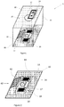
- an apparatus 1 according to a first embodiment of the invention comprises a first platform 10 having a support portion 12 that supports a plurality of test mobile devices 14, which in Figures 1 and 2 are test mobile phones.
- the apparatus also comprises a support element, which is shown in the figures in the form of a second platform 20.
- the second platform 20 is spaced from and secured to the first platform 10 by a plurality of support rods 30, with each rod 30 connecting a corner of the first platform 10 to a respective corner of the second platform 20.
- the second platform 20 is formed of a substantially transparent material, such as glass, and comprises a viewing port 22 in the form of a cut out or hole in a central region of the substantially transparent material of the second platform 20.
- the recording device 24 could be attached to and held in a fixed position on the second platform 20, by an attachment mechanism on the second platform 20.
- the attachment mechanism could be formed by one or more clips that one or more portions of the recording device 24 engage with.
- the support portion 12 of the first platform 10 is also provided with a navigation instrument 16, in the form of a compass. This is also viewable by the recording device 24, and can provide an indication of the orientation of the apparatus 1 in any content that is recorded by the recording device 24 when it resides on the second platform 20.
- the support portion 12 also includes an editable zone 17 onto which a testing person can input information relating to the testing that they intend to carry out using the apparatus 1.
- the editable zone may be one or more sheets of paper, such a pad of paper, or may be a whiteboard.
- the first platform 10 also supports a mirror assembly 40, which in the embodiment of Figures 1 and 2 consists solely of a planar mirror 42 that is offset from the planes of the first and second platforms 10, 20 by an angle of approximately 45 degrees.
- the mirror assembly 40 is positioned and orientated so that it can reflect incoming light from a front side of the apparatus 1 towards the second platform 20, and in particular, towards the lens of the recording device 24. This allows the recording device to also capture a reflected image of the view from the front side of the apparatus 1, when the apparatus 1 is being used to facilitate testing of a location-based application one or more of the mobile devices 14. This can help to provide additional reference information in the captured data, which can be used when determining whether the location-based application is working satisfactorily.
- the first platform 10 also includes two holes 18 proximate to the support portion 12 of the first platform 10. Each hole 18 can be used to pass a cable, such as a charging cable, from underneath the first platform 10 to one of the test mobile devices 14. This can be particularly beneficial when the apparatus 1 is being supported by a trolley, since the trolley can be used to house a power source, which can supply power to the mobile devices 14, via said cables. Such an arrangement may be particularly desirable where the apparatus is being used to test a number of devices at any one time, over a large test area, over a long duration of time, or any combination thereof.
- a cable such as a charging cable
- each of the test mobile devices 14 could be attached to and held in a fixed position on the first platform 10, by an attachment mechanism on the first platform 10.
- the attachment mechanism could be formed by one or more clips that one or more portions of the test mobile devices 14 engage with.
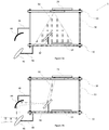
- Figures 3A and 3B shows side views of an apparatus 1 according to a second embodiment of the present invention.
- Figure 3A depicts a side view of the apparatus 1, with an indication 50 of the viewing range of the lens of the recording device 24.
- the apparatus of Figures 3A and 3B is similar to that of Figure 1 , but has an alternative mirror assembly 40.
- the mirror assembly 40 of Figures 3A and 3B also comprises a first planar mirror 42 that is disposed between the first platform 10 and the second platform 20 and is orientated at an angle that is offset from the planes of the first and second platforms 10, 20.
- the mirror assembly of Figures 3A and 3B additionally comprises a second concave mirror 44 aligned with the first planar mirror 42; and a third convex mirror 46 aligned with the second concave mirror 44.
- the second and third mirrors 44, 46 are disposed outside of the space between first and second platforms 10, 20, and fixed to the apparatus by supports 48.
- the first, second and third mirrors 42, 44, 46 of the mirror assembly 40 together define a path 60 for reflecting incoming light from a front side of the apparatus 1 towards the second platform 20, and in particular, towards the lens of the recording device 24. That is, incoming light from the front side of the apparatus 1 is reflected by the third convex mirror 46 towards the second concave mirror 44.
- the second concave mirror 44 then reflects said incoming light on towards the first planar mirror 42, which in turn reflects said incoming light towards the lens of the recording device 24.
- the recording device 24 can also capture a reflected image of the view from the front side of the apparatus 1, when the apparatus 1 is being used to facilitate testing of a location-based application on one or more of the mobile devices 14.
- the third mirror 46 By arranging for the third mirror 46 to be convex, an expanded field of view can be obtained. Furthermore, by arranging for the second mirror 44 to be concave, the incoming image can be inverted before it reaches the lens of the recording device 24, so that the image captured by the recording device 24 from the first planar mirror 42 has an orientation that matches the orientation of the field of view that an operator would have when operating the test apparatus 1.
- a test person places at least one test mobile device 14 on the support portion 12 of the first platform 10, and a recording device 24 on the second platform 20 of the apparatus 1.
- the recording device 24 is placed so that its lens overlies the viewing port 22, allowing the lens to view at least the support portion 12 of the underlying first platform 10.
- the test person initiates a location-based application on the at least one test mobile device 14; and initiates a record function on the recording device 24 such that recording device can record the view of the test mobile devices 14 on the first platform.
- the recording device 24 also records the view of the mirror 42, the navigation instrument 16, and the editable zone 17.
- the test person then transports the apparatus 1 with the supported devices 14, 24 around a test site, such as an airport, and records the performance of the location-based application on the test mobile device 14, at various different locations in the test site.
- Recorded data such as a video or image, is then sent from the recording device 24 to another person or persons for analysis.
- the recorded data may be sent directly to the additional persons during testing (such as in the form of a live stream), or may be stored on a memory in the recording device, and later sent to the additional persons after testing.
Landscapes
- Engineering & Computer Science (AREA)
- Radar, Positioning & Navigation (AREA)
- Remote Sensing (AREA)
- Physics & Mathematics (AREA)
- General Physics & Mathematics (AREA)
- Theoretical Computer Science (AREA)
- General Engineering & Computer Science (AREA)
- Manufacturing & Machinery (AREA)
- Automation & Control Theory (AREA)
- Quality & Reliability (AREA)
- Computer Hardware Design (AREA)
- Signal Processing (AREA)
- Human Computer Interaction (AREA)
- Accessories Of Cameras (AREA)
- Length Measuring Devices By Optical Means (AREA)
- Telephone Function (AREA)
- Investigating Materials By The Use Of Optical Means Adapted For Particular Applications (AREA)
Description
- This invention relates to an apparatus and method for testing a location-based application on a mobile device. It is particularly, but not exclusively, concerned with testing location-based applications for use in large public spaces, such as airports, offices, shopping centres, event stadiums and rail or road stations.
- Location-based applications on mobile devices are becoming increasingly popular, and consequently more sophisticated. One growing area of development concerns applications for use in large public spaces, such as airports, shopping centres, car parks, Hospitals and the like. Such applications can make use of Global Positioning System (GPS) to determine a device's location, but GPS technology may not work reliably indoors. So today, many applications can alternatively or additionally make use of other technologies, such as Wi-Fi triangulation or Bluetooth Low Energy Beacons, within said public spaces to provide their location specific services. For example, it may be desirable to provide an application for use in an event stadium, whereby specific services can be offered based on where a spectator is seated. For example, it may be desirable to provide users in premium seating with a service that allows them to order consumables directly to their seat. As another example, airline operators may wish to provide passengers with a guide for navigating a particular airport, such a route or set of instructions for transferring between flights or locating a particular passenger lounge.
- Such services can require very accurate location information in order to provide the full level of desired functionality, and therefore testing of such applications at the ground level is critical to ensure proper functionality. However, application developers are typically not in a position to conduct such testing themselves, and consequently testing by local personnel is normally required at each site. This testing is often done on an ad-hoc basis with the local testing person carrying the mobile device around in their hand on the site and later reporting back on any identified problems. This can be inefficient and result in problems with the applications being missed or misreported.
- Consequently, it would be desirable to improve the manner in which location-based application for mobile devices can be tested on site.
-
WO 2015/059553 A1 describes a phone holder for a mobile testing apparatus which can be adapted to securely hold a range of mobile phone models. The testing apparatus also comprises at least one camera, configured to monitor the position and/or orientation of a mobile phone supported by the phone holder, and a robot for operating the controls of the mobile phone. A mirror may be provided on the apparatus for providing the camera with a required perspective to better image the display of the mobile phone. -
US 9402016 B1 - The invention is defined by the appended claims, to which reference should be made. According to a first aspect of the invention there is provided a testing apparatus for testing a location-based application on a mobile device, the apparatus comprising: a first platform having a support portion for supporting at least one test mobile device; and a support element spaced from the first platform and held in a fixed position relative to the first platform, the support element being configured to support a recording device and permit a camera lens on the recording device to view the support portion of the first platform. The apparatus comprises a mirror assembly comprising at least one mirror disposed between the first platform and the support element and orientated at an angle that is offset from the first platform, and being configured to reflect incoming light from a front side of the apparatus towards the camera lens on the recording device.
- The apparatus of the first aspect of the present invention advantageously provides an effective means for enabling a test person to test a location-based application on a mobile device in a test environment, whilst simultaneously recording the performance of the location-based application on the mobile device. This can enable the performance of the application to be analysed by any number of additional persons (in addition to the test person), irrespective of where those additional persons are located. Consequently, a person who is more qualified to understand the performance of the application, can view one or more images or videos captured by the recording device during testing, and analyse the performance of the application. This can improve the efficiency of the testing process, and potentially lead to better identification of problems in the applications. The image or videos captured by the recording device may be sent directly to the additional persons during testing (such as in the form of a live stream), or may be stored on a memory in the recording device, and later sent to the additional persons after testing.
- Arranging for at least one test mobile device to be supported by the first platform and the recording device to be supported by a support element that is spaced from the first platform and held in a fixed position relative to the first platform, can help to improve the quality of the video or image captured, since the at least one test mobile device is less likely to move relative to the recording device during testing. This can also reduce the burden on the test person, since they are no longer required to directly hold a test mobile device in their hand during testing.
- Furthermore, the apparatus of the first aspect of the present invention can also advantageously allow a test person to simultaneously test more than one test mobile device at a time, and simultaneously capture the performance of said devices using a single recording device. This can allow for comparison analysis between different devices. For example, the performance of a location-based application a device supplied by a first manufacturer may be compared with the simultaneous performance of said application on a device supplied by a second manufacturer. This can help the likes of an application developer to determine whether their application is functioning correctly across multiple platforms and/or multiple ranges of device. Accordingly, in preferred embodiments, the first platform is configured to support two or more test mobile device, such that a recording device supported by the support element can view said two or more devices.
- The support element may take any suitable form. In some preferred embodiments, the support element is a clamp configured to grip the recording device and hold the recording device in a fixed position relative to the first platform.
- Alternatively, in some other preferred embodiments, the support portion is a second platform configured to support the recording device and hold the recording device in a fixed position relative to the first platform. In such embodiments, preferably, the second platform comprises a viewing port for enabling the camera lens on the recording device to view the support portion of the first platform. The viewing port may have any suitable shape or size. Preferably, the viewing port is provided in the form of a hole or cut-out in the second platform. Preferably the viewing port is disposed in a central region of the second platform. The viewing port can help a test person to easily determine where to locate the recording device in order for its lens to view the support portion of the first platform. Furthermore, the viewing port may allow the second platform to be formed from a non-transparent material, which may be desirable from a manufacturing perspective.
- As an alternative or in addition to a viewing port, in some preferred embodiments, at least a portion of the second platform is substantially transparent. That is, the second platform may be formed from a substantially transparent material, such as glass or plastic. Such embodiments can advantageously allow the test person to view test mobile devices on the first platform through the second platform. This can help the test person to be more certain that the location-based applications are running on the one or more test mobile devices during testing.
- The term "substantially transparent" is used herein to describe a material which allows at least a sufficient proportion of incident light to pass through it so that it is possible to see through the material. In the present invention, the substantially transparent second platform allows sufficient light to pass through it such that the support portion of the underlying first platform is visible through the second platform. The transparency of the substantially transparent material of the second platform may be evaluated in accordance with ASTM D1003 - 13.
- Where the support element is a second platform, preferably the plane of the second platform is substantially parallel to the plane of the first platform.
- The apparatus comprises a mirror assembly comprising at least one mirror disposed between the first platform and the support element and orientated at an angle that is offset from the first platform. That is, the at least one mirror preferably has a reflective surface that extends along a plane, which is offset from the plane of the first platform by a given angle. In embodiments where the support element is a second platform, preferably the at least one mirror has a reflective surface that extends along a plane, which is also offset from the plane of the second platforms by a given angle.
- Preferably, the angle is between 30 and 60 degrees, more preferably between about 40 and 50 degrees. The at least one mirror may be disposed on the support portion of the first platform. The mirror assembly is configured to reflect incoming light from a front side of the apparatus towards the support element, and in particular, towards the lens of the recording device, when a recording device is present. Accordingly, in embodiments where the support element is a second platform comprising a viewing port, the mirror assembly is configured to reflect incoming light from a front side of the apparatus towards the viewing port of the second platform. This advantageously allows the recording device to also capture a reflected image of the view from the front side of the apparatus, when the apparatus is being used to facilitate testing of a location-based application of one or more mobile devices. This can help to provide additional reference information in the captured data, which can be used when determining whether the location-based application is working satisfactorily.
- In some preferred embodiments, the mirror assembly comprises: a first planar mirror disposed between the first platform and the support element and orientated at an angle that is offset from the first platform; a second concave mirror aligned with the first planar mirror; and a third convex mirror aligned with the second concave mirror. Preferably, the second and third mirrors are disposed outside of the space between first platform and the support element. In such embodiments, the second and third mirrors are preferably attached to the remainder of the apparatus by one or more supports, such as one or more respective support bars. For example, each support may attach a mirror to the first platform. The first planar mirror may be disposed on the support portion of the first platform, or on another portion of the first platform.
- Where the mirror assembly comprises such first, second and third mirrors, said mirrors may together define a path for reflecting incoming light from a front side of the apparatus towards the support element, and in particular, towards the lens of the recording device, when a recording device is present. That is, the third convex mirror is configured to reflect incoming light from the front side of the apparatus towards the second concave mirror, the second concave mirror is configured to reflect said incoming light on towards the first planar mirror, and the first planar mirror is configured to reflect said incoming light on towards the support element, and in particular, towards the lens of the recording device, when a recording device is present.
- In this way, the recording device can also capture a reflected image of the view from the front side of the apparatus, when the apparatus is being used to facilitate testing of a location-based application one or more of the mobile devices. By arranging for the third mirror to be convex, an expanded field of view can be obtained. Furthermore, by arranging for the second mirror to be concave, the incoming image can be inverted before it reaches the lens of the recording device, so that the image captured by the recording device from the first planar mirror has an orientation that matches the orientation of the field of view that an operator would have when operating the testing apparatus. This can help to further improve the information that is recorded by the lens of the recording device when the location-based application is being tested, and thus can help to further improve the overall efficiency and effectiveness of the testing process.
- Preferably, the second concave mirror and the third convex mirror are positioned externally to the space residing between the first platform and the support element.
- Preferably, the apparatus further comprises a mechanism for attaching the recording device to the support element. For example, the attachment mechanism may be formed by one or more clips that one or more portions of the recording device engage with.
- Preferably, the apparatus further comprises a mechanism for attaching the at least one test mobile device to the first platform. For example, the attachment mechanism may be formed by one or more clips that one or more portions of the test mobile device engage with.
- Preferably, the apparatus further comprises a navigation instrument disposed on the first platform, more preferably disposed on the support portion of the first platform. Preferably, the navigation instrument is a compass. The navigation instrument may also be viewable by the recording device, and thus can provide an indication of the orientation of the apparatus in any content that is recorded by the recording device when it resides on the second platform. This may provide a useful reference for the content that is recorded.
- The support element may be spaced from the first platform and held in a fixed position relative to the first platform by any suitable means. Preferably, the apparatus comprises one or more support rods for spacing and securing the first platform relative to the support element.
- The one or more supports rods may be disposed at any suitable position on the apparatus. However, preferably, the each of the one or more support rods is disposed about a peripheral region of the apparatus. This can leave more space free in a central region of the apparatus for the one or more test devices and the recording device to be located. The one or more support rods are preferably collapsible, such as by being telescopically collapsible, to enable the support element to be positioned proximate to the first platform when not in use. This advantageously means that the apparatus will require less storage space when not in use.
- In embodiments where the support element is a clamp, the one or more support rods preferably comprises a single support rod extending from the first platform to the clamp. The single rod may comprise one or more joints for enabling the clamp to be repositioned at different points above the first platform.
- In embodiments where the support element is a second platform, preferably each of the first and second platforms has the general shape of a four sided polygon, such as a square or rectangle, and each support rod connects a corner of the first platform to a respective corner of the second platform. Using a one or more support rods to space and secure the first platform relative to the support element, can advantageously allow a test person to easily access the support portion of the first platform, whilst also providing a steady and secure attachment for a recording device.
- Preferably, the apparatus comprises a mechanism for attaching the testing apparatus to a trolley. For example, the apparatus may comprise a clamp which is configured to grip a portion of a trolley, such as a horizontal bar. Alternatively or additionally, the apparatus preferably comprises a harness for enabling the testing apparatus to be carried by a testing person.
- Preferably, one or more holes are provided on the first platform proximate to the support portion of the first platform. Each hole may be used to pass a cable, such as a charging cable, from underneath the first platform to one of the test mobile devices. This can be particularly beneficial when the apparatus is being supported by a trolley, since the trolley can be used to house a power source, which can supply power to the mobile devices, via said cables. Such an arrangement may be particularly desirable where the apparatus is being used to test a number of devices at any one time, over a large test area, over a long duration of time, or any combination thereof.
- According to a second aspect of the invention, there is provided a method for testing a location-based application on a mobile device, the method comprising the steps of: placing at least one test mobile device on a support portion of a first platform of a test apparatus; arranging for a recording device to be held by a support element of the test apparatus in a fixed position relative to the first platform, such that a camera lens of the recording device can view the at least one test mobile device on the first platform; initiating a location-based application on the at least one test mobile device; and initiating a record function on the recording device such that testing of the location-based application on the at least one test mobile device is recorded. Each step of initiating may be performed before or after each step of placing. Where the apparatus comprises additional components, such as a mirror assembly or a navigation instrument, the recording device is preferably placed on the second platform of the test apparatus, such that its camera lens can additionally view one or more of said additional components.
- The phrase "initiating a record function on the recording device" is used herein to refer to the capturing of video or image content through the lens of the recording device. The captured content may be stored on the recording device for later review by a qualified person. Alternatively or additionally, the captured content could be streamed to a qualified person for them to review the content as it is being captured. In such a scenario, the testing person is preferably provided with a communication channel for communicating with the qualified person as they are capturing the content.
- Preferably, the method further comprises the steps of: transporting the apparatus with the supported at least one test mobile device and recording device around a test site; and recording the performance of the location-based application on the at least one test mobile device, at two or more locations in the test site, by way of the lens of the recording device. Preferably, the method further comprises sending the data recorded by the recording device to one or more additional persons. This may include first storing the recorded data on a memory in the recording device.
- It will be appreciated that features described above in respect of the first aspect of the invention are equally applicable and preferable for the second aspect of the invention.
- Embodiments of the invention will now be described, by way of example only, and with reference to the accompanying drawings, in which:
-
Figure 1 shows a perspective view of an apparatus according to a first embodiment of the present invention; -
Figure 2 shows a perspective view of the first platform of the apparatus ofFigure 1 ; and -
Figures 3A and 3B shows side views of an apparatus according to a second embodiment of the present invention. - As can be seen from
Figures 1 and 2 , anapparatus 1 according to a first embodiment of the invention comprises afirst platform 10 having asupport portion 12 that supports a plurality of testmobile devices 14, which inFigures 1 and 2 are test mobile phones. - The apparatus also comprises a support element, which is shown in the figures in the form of a
second platform 20. Thesecond platform 20 is spaced from and secured to thefirst platform 10 by a plurality ofsupport rods 30, with eachrod 30 connecting a corner of thefirst platform 10 to a respective corner of thesecond platform 20. Thesecond platform 20 is formed of a substantially transparent material, such as glass, and comprises a viewing port 22 in the form of a cut out or hole in a central region of the substantially transparent material of thesecond platform 20. - A
recording device 24, in the form of a tablet device, is disposed on thesecond platform 20, in a position whereby a lens on therecording device 24 overlies the viewing port 22. This allows the lens on therecording device 24 to view thesupport portion 12 of thefirst platform 10, and in particular, to view thetest devices 14 that are disposed on thesupport portion 12 of thefirst platform 10. It will be appreciated that therecording device 24 could alternatively be disposed in other positions on thesecond platform 20, whereby the lens of the recording device overlies the substantially transparent material of thesecond platform 20, and the lens on therecording device 24 be capable of viewing thesupport portion 12 of thefirst platform 10 through the transparent material of thesecond platform 20. - Although not visible in
Figure 1 , therecording device 24 could be attached to and held in a fixed position on thesecond platform 20, by an attachment mechanism on thesecond platform 20. The attachment mechanism could be formed by one or more clips that one or more portions of therecording device 24 engage with. - As best seen from
Figure 2 , thesupport portion 12 of thefirst platform 10 is also provided with anavigation instrument 16, in the form of a compass. This is also viewable by therecording device 24, and can provide an indication of the orientation of theapparatus 1 in any content that is recorded by therecording device 24 when it resides on thesecond platform 20. Thesupport portion 12 also includes aneditable zone 17 onto which a testing person can input information relating to the testing that they intend to carry out using theapparatus 1. The editable zone may be one or more sheets of paper, such a pad of paper, or may be a whiteboard. - The
first platform 10 also supports amirror assembly 40, which in the embodiment ofFigures 1 and 2 consists solely of aplanar mirror 42 that is offset from the planes of the first andsecond platforms mirror assembly 40 is positioned and orientated so that it can reflect incoming light from a front side of theapparatus 1 towards thesecond platform 20, and in particular, towards the lens of therecording device 24. This allows the recording device to also capture a reflected image of the view from the front side of theapparatus 1, when theapparatus 1 is being used to facilitate testing of a location-based application one or more of themobile devices 14. This can help to provide additional reference information in the captured data, which can be used when determining whether the location-based application is working satisfactorily. - The
first platform 10 also includes twoholes 18 proximate to thesupport portion 12 of thefirst platform 10. Eachhole 18 can be used to pass a cable, such as a charging cable, from underneath thefirst platform 10 to one of the testmobile devices 14. This can be particularly beneficial when theapparatus 1 is being supported by a trolley, since the trolley can be used to house a power source, which can supply power to themobile devices 14, via said cables. Such an arrangement may be particularly desirable where the apparatus is being used to test a number of devices at any one time, over a large test area, over a long duration of time, or any combination thereof. - Although not visible in
Figures 1 or 2 , each of the testmobile devices 14 could be attached to and held in a fixed position on thefirst platform 10, by an attachment mechanism on thefirst platform 10. The attachment mechanism could be formed by one or more clips that one or more portions of the testmobile devices 14 engage with. -
Figures 3A and 3B shows side views of anapparatus 1 according to a second embodiment of the present invention.Figure 3A depicts a side view of theapparatus 1, with anindication 50 of the viewing range of the lens of therecording device 24. - The apparatus of
Figures 3A and 3B is similar to that ofFigure 1 , but has analternative mirror assembly 40. In particular, as with the mirror assembly ofFigure 1 , themirror assembly 40 ofFigures 3A and 3B also comprises a firstplanar mirror 42 that is disposed between thefirst platform 10 and thesecond platform 20 and is orientated at an angle that is offset from the planes of the first andsecond platforms Figures 3A and 3B additionally comprises a secondconcave mirror 44 aligned with the firstplanar mirror 42; and a thirdconvex mirror 46 aligned with the secondconcave mirror 44. - The second and
third mirrors second platforms Figure 3B , the first, second andthird mirrors mirror assembly 40 together define apath 60 for reflecting incoming light from a front side of theapparatus 1 towards thesecond platform 20, and in particular, towards the lens of therecording device 24. That is, incoming light from the front side of theapparatus 1 is reflected by the thirdconvex mirror 46 towards the secondconcave mirror 44. The secondconcave mirror 44 then reflects said incoming light on towards the firstplanar mirror 42, which in turn reflects said incoming light towards the lens of therecording device 24. In this way, therecording device 24 can also capture a reflected image of the view from the front side of theapparatus 1, when theapparatus 1 is being used to facilitate testing of a location-based application on one or more of themobile devices 14. By arranging for thethird mirror 46 to be convex, an expanded field of view can be obtained. Furthermore, by arranging for thesecond mirror 44 to be concave, the incoming image can be inverted before it reaches the lens of therecording device 24, so that the image captured by therecording device 24 from the firstplanar mirror 42 has an orientation that matches the orientation of the field of view that an operator would have when operating thetest apparatus 1. - To use the
apparatus 1 of any ofFigures 1 to 3B , a test person places at least one testmobile device 14 on thesupport portion 12 of thefirst platform 10, and arecording device 24 on thesecond platform 20 of theapparatus 1. Therecording device 24 is placed so that its lens overlies the viewing port 22, allowing the lens to view at least thesupport portion 12 of the underlyingfirst platform 10. Before or after placement of thedevices 14, 214 the test person initiates a location-based application on the at least one testmobile device 14; and initiates a record function on therecording device 24 such that recording device can record the view of the testmobile devices 14 on the first platform. Additionally, in the embodiments ofFigures 1 to 3B , therecording device 24 also records the view of themirror 42, thenavigation instrument 16, and theeditable zone 17. - The test person then transports the
apparatus 1 with the supporteddevices mobile device 14, at various different locations in the test site. Recorded data, such as a video or image, is then sent from therecording device 24 to another person or persons for analysis. The recorded data may be sent directly to the additional persons during testing (such as in the form of a live stream), or may be stored on a memory in the recording device, and later sent to the additional persons after testing. - Although the above description relates to testing of location-based applications for use in an airport, it is to be understood that the method and apparatus of the present invention is not limited to airports but may be applied to any other space, such as shopping centres, offices, event stadiums and rail or road stations. Many other variations and modifications are possible and will occur to those skilled in the art without departing from the scope of the invention which is determined by the following claims.
Claims (15)
- A testing apparatus (1) for testing a location-based application on a mobile device, the apparatus comprising:a first platform (10) having a support portion (12) for supporting at least one test mobile device (14);a support element (20) spaced from the first platform (10) and held in a fixed position relative to the first platform (10), the support element (20) being configured to support a recording device (24) and permit a camera lens on the recording device (24) to view the support portion of the first platform (10); and:
a mirror assembly (40) comprising at least one mirror (42) disposed between the first platform (10) and the support element (20) and orientated at an angle that is offset from the first platform (10), and being configured to reflect incoming light from a front side of the apparatus towards the camera lens on the recording device (24). - An apparatus (1) according to claim 1, wherein the support element (20) is a clamp configured to grip the recording device (24) and hold the recording device in a fixed position relative to the first platform (10).
- An apparatus (1) according to claim 1, wherein the support element (20) is a second platform configured to support the recording device (24) and hold the recording device in a fixed position relative to the first platform (10).
- An apparatus (1) according to claim 3, wherein the second platform comprises a viewing port (22) for enabling the camera lens on the recording device (24) to view the support portion (12) of the first platform.
- An apparatus (1) according to claim 3 or claim 4, wherein at least a portion of the second platform is substantially transparent.
- An apparatus (1) according to claim 5, wherein the mirror assembly (40) comprises:a first planar mirror (42) disposed between the first platform (10) and the support element (20) and orientated at an angle that is offset from the first platform (10);a second concave mirror (44) aligned with the first planar mirror (42); anda third convex mirror (46) aligned with the second concave mirror (44).
- An apparatus (1)according to claim 6, wherein the second concave mirror (44) and the third convex mirror (46) are positioned externally to the space residing between the first platform (10) and the support element (20).
- An apparatus (1) according to any one of the preceding claims, further comprising a mechanism for attaching the recording device (24) to the support element (20).
- An apparatus (1) according to any one of the preceding claims, further comprising a mechanism for attaching the at least one test mobile device (14) to the first platform (10).
- An apparatus (1) according to any one of the preceding claims, further comprising a navigation instrument (16) disposed on the first platform.
- An apparatus (1) according to any one of the preceding claims, further comprising one or more support rods (30) for securing the first platform (10) relative to the support element (20).
- An apparatus (1) according to any one of the preceding claims, further comprising a mechanism for attaching the apparatus (1) to a trolley.
- An apparatus (1) according to any one of the preceding claims, further comprising a harness for enabling the apparatus (1) to be carried by a testing person.
- An apparatus according to any one of the preceding claims, wherein one or more holes (18) are provided on the first platform proximate to the support portion of the first platform.
- A method for testing a location-based application on a mobile device, the method comprising:placing at least one test mobile device (14) on a support portion (12) of a first platform (10) of a testing apparatus (1);arranging for a recording device (24) to be held by a support element (20) of the testing apparatus (1) in a fixed position relative to the first platform (10), such that a camera lens of the recording device (24) can view the at least one test mobile device (14) on the first platform (10) and a mirror assembly (40) comprising at least one mirror (42) disposed between the first platform (10) and the support element (20) and orientated at an angle that is offset from the first platform (10), is configured to reflect incoming light from a front side of the apparatus (10) towards the camera lens on the recording device (24);initiating a location-based application on the at least one test mobile device (14); andinitiating a record function on the recording device (24) such that testing of the location-based application on the at least one test mobile device (14) is recorded.
Applications Claiming Priority (3)
| Application Number | Priority Date | Filing Date | Title |
|---|---|---|---|
| US15/454,779 US10620013B2 (en) | 2017-03-09 | 2017-03-09 | Testing apparatus and method for testing a location-based application on a mobile device |
| GB1802179.0A GB2561658B (en) | 2017-03-09 | 2018-02-09 | Testing apparatus and method for testing a location-based application on a mobile device |
| PCT/IB2018/051531 WO2018163108A1 (en) | 2017-03-09 | 2018-03-08 | Testing apparatus and method for testing a location-based application on a mobile device |
Publications (2)
| Publication Number | Publication Date |
|---|---|
| EP3593084A1 EP3593084A1 (en) | 2020-01-15 |
| EP3593084B1 true EP3593084B1 (en) | 2021-12-15 |
Family
ID=61731248
Family Applications (1)
| Application Number | Title | Priority Date | Filing Date |
|---|---|---|---|
| EP18716338.1A Active EP3593084B1 (en) | 2017-03-09 | 2018-03-08 | Testing apparatus and method for testing a location-based application on a mobile device |
Country Status (6)
| Country | Link |
|---|---|
| US (1) | US10620013B2 (en) |
| EP (1) | EP3593084B1 (en) |
| JP (1) | JP7133557B2 (en) |
| ES (1) | ES2903306T3 (en) |
| GB (1) | GB2561658B (en) |
| WO (1) | WO2018163108A1 (en) |
Families Citing this family (2)
| Publication number | Priority date | Publication date | Assignee | Title |
|---|---|---|---|---|
| CN113468068B (en) * | 2021-07-21 | 2023-08-25 | 腾讯科技(深圳)有限公司 | Virtual resource testing method and device, storage medium and electronic equipment |
| CH720422A9 (en) * | 2023-01-06 | 2025-04-30 | Portmann Daniel | Mount and method for testing a safety-critical mobile phone application |
Family Cites Families (71)
| Publication number | Priority date | Publication date | Assignee | Title |
|---|---|---|---|---|
| US4929819A (en) * | 1988-12-12 | 1990-05-29 | Ncr Corporation | Method and apparatus for customer performed article scanning in self-service shopping |
| JPH07334368A (en) | 1994-06-08 | 1995-12-22 | Hitachi Ltd | Knowledge-based system and recognition system |
| US6259405B1 (en) | 1995-06-06 | 2001-07-10 | Wayport, Inc. | Geographic based communications service |
| US5793639A (en) | 1995-10-24 | 1998-08-11 | Toyota Jidosha Kabushiki Kaisha | Baggage receiving and handling method in airport, baggage receiving and handling system in airport, and baggage automatic handling apparatus |
| US5897620A (en) | 1997-07-08 | 1999-04-27 | Priceline.Com Inc. | Method and apparatus for the sale of airline-specified flight tickets |
| JP3672430B2 (en) * | 1998-01-30 | 2005-07-20 | 松下電器産業株式会社 | Cream solder evaluation apparatus and evaluation method |
| US6044353A (en) | 1998-03-10 | 2000-03-28 | Pugliese, Iii; Anthony V. | Baggage check-in and security system and method |
| US6522998B1 (en) * | 1998-10-13 | 2003-02-18 | Breed Automotive Technology, Inc. | Sled test apparatus and method for simulating pre-impact crash event |
| WO2001001366A2 (en) | 1999-06-25 | 2001-01-04 | Telemonitor, Inc. | Smart remote monitoring system and method |
| US6735630B1 (en) | 1999-10-06 | 2004-05-11 | Sensoria Corporation | Method for collecting data using compact internetworked wireless integrated network sensors (WINS) |
| US7599847B2 (en) | 2000-06-09 | 2009-10-06 | Airport America | Automated internet based interactive travel planning and management system |
| US6414635B1 (en) | 2000-10-23 | 2002-07-02 | Wayport, Inc. | Geographic-based communication service system with more precise determination of a user's known geographic location |
| AU2002226941A1 (en) | 2000-11-20 | 2002-06-03 | Ecrio, Inc. | Method for downloading bar code encoded information with a mobile communication |
| US6758394B2 (en) | 2001-07-09 | 2004-07-06 | Infonox On The Web | Identity verification and enrollment system for self-service devices |
| EP1308864A1 (en) | 2001-11-02 | 2003-05-07 | Hewlett-Packard Company | Passenger management system and method and electronic device |
| JP2003157984A (en) | 2001-11-19 | 2003-05-30 | Hitachi Ltd | Street light control system linked to location information terminal |
| JP2003185783A (en) | 2001-12-20 | 2003-07-03 | Hitachi Ltd | Furnace visual inspection device |
| WO2003063103A1 (en) | 2002-01-18 | 2003-07-31 | Georgia Tech Research Corporation | Monitoring and tracking of assets by utilizing wireless communications |
| GB0211644D0 (en) | 2002-05-21 | 2002-07-03 | Wesby Philip B | System and method for remote asset management |
| US6746141B2 (en) * | 2002-09-26 | 2004-06-08 | American Auto Accessories, Inc. | Auxiliary rearview mirror and light assembly |
| US20090266882A1 (en) | 2003-06-17 | 2009-10-29 | Sajkowsky James M | Smart passport system for monitoring and recording activity and data relating to persons |
| US7275689B2 (en) | 2003-09-05 | 2007-10-02 | Bcode Pty Ltd | Baggage check-in using short message device |
| US20050258230A1 (en) | 2004-05-18 | 2005-11-24 | Keith Wiater | Processing passengers, baggage and cargo |
| EP1872294B1 (en) | 2005-04-21 | 2017-11-08 | Microsoft Technology Licensing, LLC | Virtual earth |
| KR100771130B1 (en) | 2005-05-23 | 2007-10-30 | 삼성전자주식회사 | Service purchase system and method using RF-ID tag and RF-ID tag |
| US8229458B2 (en) | 2007-04-08 | 2012-07-24 | Enhanced Geographic Llc | Systems and methods to determine the name of a location visited by a user of a wireless device |
| US8631358B2 (en) | 2007-10-10 | 2014-01-14 | Apple Inc. | Variable device graphical user interface |
| JP5166316B2 (en) | 2009-02-20 | 2013-03-21 | 株式会社東芝 | Situation recognition device and situation recognition method |
| US8730925B2 (en) | 2009-04-09 | 2014-05-20 | Motorola Mobility Llc | Method and apparatus for generating reference signals for accurate time-difference of arrival estimation |
| US8423457B1 (en) | 2009-04-13 | 2013-04-16 | Amazon Technologies, Inc. | Anonymous mobile payments |
| WO2010123089A1 (en) | 2009-04-24 | 2010-10-28 | 株式会社日立メディコ | Ultrasonic imaging device |
| DE102009020228A1 (en) | 2009-05-07 | 2010-11-11 | Siemens Aktiengesellschaft | Global positioning system-based positioning system for locating luggage pieces of luggage transporting system in airport, has receiver with modules of mobile telephones connected with transporting goods during transportation |
| GB2470774B (en) * | 2009-06-05 | 2012-10-10 | Ronford Baker Engineering Company Ltd | Support |
| KR101615542B1 (en) | 2009-06-10 | 2016-04-26 | 삼성전자주식회사 | Radio frequency identification system and method for authentication therein |
| US9217691B2 (en) * | 2009-08-19 | 2015-12-22 | Frontone Gmbh | System for investigating a test body |
| EP2478328B1 (en) | 2009-09-18 | 2016-07-27 | Carl Zeiss SMT GmbH | Method of measuring a shape of an optical surface |
| JP5390612B2 (en) | 2009-11-06 | 2014-01-15 | パナソニック株式会社 | Communication apparatus and communication method |
| JP2011103609A (en) | 2009-11-11 | 2011-05-26 | Japan Novel Corp | Apparatus for checking function of equipment and device |
| US9239246B2 (en) | 2011-10-19 | 2016-01-19 | Google Inc. | Method, system, and computer program product for visual disambiguation for directions queries |
| US20140340680A1 (en) | 2011-11-30 | 2014-11-20 | Labsphere, Inc. | Apparatus and method for mobile device camera testing |
| US9026461B2 (en) | 2012-01-23 | 2015-05-05 | Bank Of America Corporation | Enhanced mobile application for assisting users at a point of transaction |
| US9024752B2 (en) | 2012-04-05 | 2015-05-05 | Amadeus S.A.S. | Traveler hurry status monitor |
| US9453786B2 (en) * | 2012-04-05 | 2016-09-27 | Biodynamic Research Corporation | System force-deformation modeling apparatuses and methods |
| US8798332B2 (en) | 2012-05-15 | 2014-08-05 | Google Inc. | Contact lenses |
| US9015654B2 (en) | 2012-08-13 | 2015-04-21 | Bitbar Technologies Oy | System for providing test environments for executing and analysing test routines |
| US20140069973A1 (en) * | 2012-09-13 | 2014-03-13 | Robert Michael Peck | Universal Fit Tablet Computer, Smartphone, Electronic Device Holding Display Unit that Fits onto Grocery or Shopping Carts |
| US8665238B1 (en) | 2012-09-21 | 2014-03-04 | Google Inc. | Determining a dominant hand of a user of a computing device |
| US9423498B1 (en) | 2012-09-25 | 2016-08-23 | Google Inc. | Use of motion data in the processing of automotive radar image processing |
| JP2015061577A (en) | 2013-01-18 | 2015-04-02 | 株式会社東芝 | Movement-information processing device |
| US9134955B2 (en) | 2013-01-24 | 2015-09-15 | Intel Corporation | Customization of a vehicle |
| US9141325B2 (en) | 2013-02-01 | 2015-09-22 | Amadeus S.A.S. | Communications management |
| US9589262B2 (en) | 2013-03-01 | 2017-03-07 | Samsung Pay, Inc. | Mobile checkout systems and methods |
| US20140339278A1 (en) * | 2013-05-16 | 2014-11-20 | Brian Ditore | Adjustable electronic device holder mountable to a cart handle |
| JP5828165B2 (en) | 2013-07-23 | 2015-12-02 | 計測技研株式会社 | Internal cavity cross-sectional shape measuring apparatus and internal air cross-sectional shape measuring method |
| WO2015059508A1 (en) | 2013-10-24 | 2015-04-30 | Teleplan Technology B.V. | Method and apparatus for testing cell phones |
| US8949142B1 (en) | 2013-12-19 | 2015-02-03 | Opentable, Inc. | Mobile payments integrated with a booking system |
| US20190073656A1 (en) * | 2014-01-20 | 2019-03-07 | Cust2mate Ltd. | Shopping Cart and System |
| US9589405B2 (en) | 2014-04-07 | 2017-03-07 | Iwallet Corporation | Smartphone controlled biometric and Bluetooth enabled smart wallet system |
| US9402016B1 (en) | 2014-04-09 | 2016-07-26 | Miguel Alejandro Hidalgo | Electronic device mount |
| JP6133231B2 (en) | 2014-04-18 | 2017-05-24 | 株式会社日立製作所 | X-ray energy spectrum measuring method, X-ray energy spectrum measuring apparatus and X-ray CT apparatus |
| US20150306824A1 (en) | 2014-04-25 | 2015-10-29 | Rememborines Inc. | System, apparatus and method, for producing a three dimensional printed figurine |
| US9275550B1 (en) | 2014-10-04 | 2016-03-01 | Rockwell Collins, Inc. | Dynamic ground vehicle tracking and reporting system |
| US20160152350A1 (en) | 2014-12-01 | 2016-06-02 | The Boeing Company | Locating luggage with rfid tags |
| US20160180255A1 (en) | 2014-12-23 | 2016-06-23 | Unisys Corporation | Method and system for managing airport baggage |
| KR102363632B1 (en) | 2014-12-29 | 2022-02-16 | 삼성전자주식회사 | Method and apparatus for generating distress signal |
| US9552564B1 (en) | 2015-03-19 | 2017-01-24 | Amazon Technologies, Inc. | Autonomous delivery transportation network |
| US20170004444A1 (en) | 2015-07-01 | 2017-01-05 | Amadeus S.A.S. | Baggage tracking system |
| US20170032263A1 (en) | 2015-07-27 | 2017-02-02 | The Boeing Company | Methods and systems for context driven information services and advanced decision making |
| US10180621B2 (en) * | 2015-08-18 | 2019-01-15 | DISH Technologies L.L.C. | Systems, methods, and devices for usability testing |
| JP6560989B2 (en) | 2016-01-19 | 2019-08-14 | 株式会社日立製作所 | Biometric authentication device and control method thereof |
| WO2018144650A1 (en) * | 2017-01-31 | 2018-08-09 | Focal Systems, Inc. | Automated checkout system through mobile shopping units |
-
2017
- 2017-03-09 US US15/454,779 patent/US10620013B2/en active Active
-
2018
- 2018-02-09 GB GB1802179.0A patent/GB2561658B/en active Active
- 2018-03-08 JP JP2019541073A patent/JP7133557B2/en active Active
- 2018-03-08 WO PCT/IB2018/051531 patent/WO2018163108A1/en not_active Ceased
- 2018-03-08 ES ES18716338T patent/ES2903306T3/en active Active
- 2018-03-08 EP EP18716338.1A patent/EP3593084B1/en active Active
Also Published As
| Publication number | Publication date |
|---|---|
| JP7133557B2 (en) | 2022-09-08 |
| US20180259358A1 (en) | 2018-09-13 |
| JP2020516106A (en) | 2020-05-28 |
| EP3593084A1 (en) | 2020-01-15 |
| GB2561658B (en) | 2020-07-08 |
| US10620013B2 (en) | 2020-04-14 |
| GB2561658A (en) | 2018-10-24 |
| ES2903306T3 (en) | 2022-03-31 |
| WO2018163108A1 (en) | 2018-09-13 |
| GB201802179D0 (en) | 2018-03-28 |
Similar Documents
| Publication | Publication Date | Title |
|---|---|---|
| JP4469471B2 (en) | Wide viewing angle multidirectional image acquisition device for moving body and wide viewing angle multidirectional image acquisition system for moving body | |
| US11722646B2 (en) | System and method for interactive aerial imaging | |
| JP5349055B2 (en) | Multi-lens array system and method | |
| US20020167536A1 (en) | Method, system and device for augmented reality | |
| EP1901560B1 (en) | Photographic system | |
| CN109558957A (en) | Select vehicle boarding position | |
| CA2603329C (en) | Method and system for producing an image from a vehicle | |
| CN111080832A (en) | Inspection method and system for power transmission line tower | |
| US20180130008A1 (en) | System and Method for Aerial Vehicle Automatic Landing and Cargo Delivery | |
| US20110071753A1 (en) | Method, system, and recording medium for navigating vehicle | |
| US20110234817A1 (en) | Image capturing terminal, external terminal, image capturing system, and image capturing method | |
| EP3593084B1 (en) | Testing apparatus and method for testing a location-based application on a mobile device | |
| EP3287988B1 (en) | Modelling system and method | |
| CN104567903A (en) | Method and device for acquiring navigation information | |
| US20200193835A1 (en) | Traffic control apparatus, traffic control system, traffic control method, and non-transitory computer recording medium | |
| US11657574B2 (en) | Systems and methods for providing an audio-guided virtual reality tour | |
| CN103763470A (en) | Portable scene shooting device | |
| CN106657792A (en) | Shared viewing device | |
| US11138635B2 (en) | Mobile media topper | |
| US7408665B2 (en) | Print service system and print service server | |
| US11449299B2 (en) | Initiating and determining viewing distance to a display screen | |
| CN112558008B (en) | Navigation methods, systems, equipment and media based on optical communication devices | |
| JP7164575B2 (en) | Safety management system | |
| CN104798387B (en) | The method and system of mobile communication equipment is utilized in fixed communication infrastructure | |
| GB2529386A (en) | Hand held parking control device |
Legal Events
| Date | Code | Title | Description |
|---|---|---|---|
| STAA | Information on the status of an ep patent application or granted ep patent |
Free format text: STATUS: UNKNOWN |
|
| STAA | Information on the status of an ep patent application or granted ep patent |
Free format text: STATUS: THE INTERNATIONAL PUBLICATION HAS BEEN MADE |
|
| PUAI | Public reference made under article 153(3) epc to a published international application that has entered the european phase |
Free format text: ORIGINAL CODE: 0009012 |
|
| STAA | Information on the status of an ep patent application or granted ep patent |
Free format text: STATUS: REQUEST FOR EXAMINATION WAS MADE |
|
| 17P | Request for examination filed |
Effective date: 20191009 |
|
| AK | Designated contracting states |
Kind code of ref document: A1 Designated state(s): AL AT BE BG CH CY CZ DE DK EE ES FI FR GB GR HR HU IE IS IT LI LT LU LV MC MK MT NL NO PL PT RO RS SE SI SK SM TR |
|
| AX | Request for extension of the european patent |
Extension state: BA ME |
|
| DAV | Request for validation of the european patent (deleted) | ||
| DAX | Request for extension of the european patent (deleted) | ||
| REG | Reference to a national code |
Ref country code: HK Ref legal event code: DE Ref document number: 40019072 Country of ref document: HK |
|
| GRAP | Despatch of communication of intention to grant a patent |
Free format text: ORIGINAL CODE: EPIDOSNIGR1 |
|
| STAA | Information on the status of an ep patent application or granted ep patent |
Free format text: STATUS: GRANT OF PATENT IS INTENDED |
|
| INTG | Intention to grant announced |
Effective date: 20210706 |
|
| GRAS | Grant fee paid |
Free format text: ORIGINAL CODE: EPIDOSNIGR3 |
|
| GRAA | (expected) grant |
Free format text: ORIGINAL CODE: 0009210 |
|
| STAA | Information on the status of an ep patent application or granted ep patent |
Free format text: STATUS: THE PATENT HAS BEEN GRANTED |
|
| AK | Designated contracting states |
Kind code of ref document: B1 Designated state(s): AL AT BE BG CH CY CZ DE DK EE ES FI FR GB GR HR HU IE IS IT LI LT LU LV MC MK MT NL NO PL PT RO RS SE SI SK SM TR |
|
| REG | Reference to a national code |
Ref country code: GB Ref legal event code: FG4D Ref country code: CH Ref legal event code: EP |
|
| REG | Reference to a national code |
Ref country code: IE Ref legal event code: FG4D Ref country code: DE Ref legal event code: R096 Ref document number: 602018028175 Country of ref document: DE |
|
| REG | Reference to a national code |
Ref country code: AT Ref legal event code: REF Ref document number: 1455793 Country of ref document: AT Kind code of ref document: T Effective date: 20220115 |
|
| REG | Reference to a national code |
Ref country code: NL Ref legal event code: FP |
|
| REG | Reference to a national code |
Ref country code: ES Ref legal event code: FG2A Ref document number: 2903306 Country of ref document: ES Kind code of ref document: T3 Effective date: 20220331 |
|
| REG | Reference to a national code |
Ref country code: LT Ref legal event code: MG9D |
|
| PG25 | Lapsed in a contracting state [announced via postgrant information from national office to epo] |
Ref country code: RS Free format text: LAPSE BECAUSE OF FAILURE TO SUBMIT A TRANSLATION OF THE DESCRIPTION OR TO PAY THE FEE WITHIN THE PRESCRIBED TIME-LIMIT Effective date: 20211215 Ref country code: LT Free format text: LAPSE BECAUSE OF FAILURE TO SUBMIT A TRANSLATION OF THE DESCRIPTION OR TO PAY THE FEE WITHIN THE PRESCRIBED TIME-LIMIT Effective date: 20211215 Ref country code: FI Free format text: LAPSE BECAUSE OF FAILURE TO SUBMIT A TRANSLATION OF THE DESCRIPTION OR TO PAY THE FEE WITHIN THE PRESCRIBED TIME-LIMIT Effective date: 20211215 Ref country code: BG Free format text: LAPSE BECAUSE OF FAILURE TO SUBMIT A TRANSLATION OF THE DESCRIPTION OR TO PAY THE FEE WITHIN THE PRESCRIBED TIME-LIMIT Effective date: 20220315 |
|
| REG | Reference to a national code |
Ref country code: AT Ref legal event code: MK05 Ref document number: 1455793 Country of ref document: AT Kind code of ref document: T Effective date: 20211215 |
|
| PG25 | Lapsed in a contracting state [announced via postgrant information from national office to epo] |
Ref country code: SE Free format text: LAPSE BECAUSE OF FAILURE TO SUBMIT A TRANSLATION OF THE DESCRIPTION OR TO PAY THE FEE WITHIN THE PRESCRIBED TIME-LIMIT Effective date: 20211215 Ref country code: NO Free format text: LAPSE BECAUSE OF FAILURE TO SUBMIT A TRANSLATION OF THE DESCRIPTION OR TO PAY THE FEE WITHIN THE PRESCRIBED TIME-LIMIT Effective date: 20220315 Ref country code: LV Free format text: LAPSE BECAUSE OF FAILURE TO SUBMIT A TRANSLATION OF THE DESCRIPTION OR TO PAY THE FEE WITHIN THE PRESCRIBED TIME-LIMIT Effective date: 20211215 Ref country code: HR Free format text: LAPSE BECAUSE OF FAILURE TO SUBMIT A TRANSLATION OF THE DESCRIPTION OR TO PAY THE FEE WITHIN THE PRESCRIBED TIME-LIMIT Effective date: 20211215 Ref country code: GR Free format text: LAPSE BECAUSE OF FAILURE TO SUBMIT A TRANSLATION OF THE DESCRIPTION OR TO PAY THE FEE WITHIN THE PRESCRIBED TIME-LIMIT Effective date: 20220316 |
|
| PG25 | Lapsed in a contracting state [announced via postgrant information from national office to epo] |
Ref country code: SM Free format text: LAPSE BECAUSE OF FAILURE TO SUBMIT A TRANSLATION OF THE DESCRIPTION OR TO PAY THE FEE WITHIN THE PRESCRIBED TIME-LIMIT Effective date: 20211215 Ref country code: SK Free format text: LAPSE BECAUSE OF FAILURE TO SUBMIT A TRANSLATION OF THE DESCRIPTION OR TO PAY THE FEE WITHIN THE PRESCRIBED TIME-LIMIT Effective date: 20211215 Ref country code: RO Free format text: LAPSE BECAUSE OF FAILURE TO SUBMIT A TRANSLATION OF THE DESCRIPTION OR TO PAY THE FEE WITHIN THE PRESCRIBED TIME-LIMIT Effective date: 20211215 Ref country code: PT Free format text: LAPSE BECAUSE OF FAILURE TO SUBMIT A TRANSLATION OF THE DESCRIPTION OR TO PAY THE FEE WITHIN THE PRESCRIBED TIME-LIMIT Effective date: 20220418 Ref country code: EE Free format text: LAPSE BECAUSE OF FAILURE TO SUBMIT A TRANSLATION OF THE DESCRIPTION OR TO PAY THE FEE WITHIN THE PRESCRIBED TIME-LIMIT Effective date: 20211215 Ref country code: CZ Free format text: LAPSE BECAUSE OF FAILURE TO SUBMIT A TRANSLATION OF THE DESCRIPTION OR TO PAY THE FEE WITHIN THE PRESCRIBED TIME-LIMIT Effective date: 20211215 |
|
| PG25 | Lapsed in a contracting state [announced via postgrant information from national office to epo] |
Ref country code: PL Free format text: LAPSE BECAUSE OF FAILURE TO SUBMIT A TRANSLATION OF THE DESCRIPTION OR TO PAY THE FEE WITHIN THE PRESCRIBED TIME-LIMIT Effective date: 20211215 Ref country code: AT Free format text: LAPSE BECAUSE OF FAILURE TO SUBMIT A TRANSLATION OF THE DESCRIPTION OR TO PAY THE FEE WITHIN THE PRESCRIBED TIME-LIMIT Effective date: 20211215 |
|
| REG | Reference to a national code |
Ref country code: DE Ref legal event code: R097 Ref document number: 602018028175 Country of ref document: DE |
|
| PG25 | Lapsed in a contracting state [announced via postgrant information from national office to epo] |
Ref country code: IS Free format text: LAPSE BECAUSE OF FAILURE TO SUBMIT A TRANSLATION OF THE DESCRIPTION OR TO PAY THE FEE WITHIN THE PRESCRIBED TIME-LIMIT Effective date: 20220415 |
|
| PLBE | No opposition filed within time limit |
Free format text: ORIGINAL CODE: 0009261 |
|
| STAA | Information on the status of an ep patent application or granted ep patent |
Free format text: STATUS: NO OPPOSITION FILED WITHIN TIME LIMIT |
|
| PG25 | Lapsed in a contracting state [announced via postgrant information from national office to epo] |
Ref country code: MC Free format text: LAPSE BECAUSE OF FAILURE TO SUBMIT A TRANSLATION OF THE DESCRIPTION OR TO PAY THE FEE WITHIN THE PRESCRIBED TIME-LIMIT Effective date: 20211215 Ref country code: DK Free format text: LAPSE BECAUSE OF FAILURE TO SUBMIT A TRANSLATION OF THE DESCRIPTION OR TO PAY THE FEE WITHIN THE PRESCRIBED TIME-LIMIT Effective date: 20211215 Ref country code: AL Free format text: LAPSE BECAUSE OF FAILURE TO SUBMIT A TRANSLATION OF THE DESCRIPTION OR TO PAY THE FEE WITHIN THE PRESCRIBED TIME-LIMIT Effective date: 20211215 |
|
| REG | Reference to a national code |
Ref country code: CH Ref legal event code: PL |
|
| 26N | No opposition filed |
Effective date: 20220916 |
|
| PG25 | Lapsed in a contracting state [announced via postgrant information from national office to epo] |
Ref country code: SI Free format text: LAPSE BECAUSE OF FAILURE TO SUBMIT A TRANSLATION OF THE DESCRIPTION OR TO PAY THE FEE WITHIN THE PRESCRIBED TIME-LIMIT Effective date: 20211215 |
|
| REG | Reference to a national code |
Ref country code: BE Ref legal event code: MM Effective date: 20220331 |
|
| PG25 | Lapsed in a contracting state [announced via postgrant information from national office to epo] |
Ref country code: LU Free format text: LAPSE BECAUSE OF NON-PAYMENT OF DUE FEES Effective date: 20220308 Ref country code: LI Free format text: LAPSE BECAUSE OF NON-PAYMENT OF DUE FEES Effective date: 20220331 Ref country code: IE Free format text: LAPSE BECAUSE OF NON-PAYMENT OF DUE FEES Effective date: 20220308 Ref country code: CH Free format text: LAPSE BECAUSE OF NON-PAYMENT OF DUE FEES Effective date: 20220331 |
|
| PG25 | Lapsed in a contracting state [announced via postgrant information from national office to epo] |
Ref country code: BE Free format text: LAPSE BECAUSE OF NON-PAYMENT OF DUE FEES Effective date: 20220331 |
|
| P01 | Opt-out of the competence of the unified patent court (upc) registered |
Effective date: 20230530 |
|
| PG25 | Lapsed in a contracting state [announced via postgrant information from national office to epo] |
Ref country code: MK Free format text: LAPSE BECAUSE OF FAILURE TO SUBMIT A TRANSLATION OF THE DESCRIPTION OR TO PAY THE FEE WITHIN THE PRESCRIBED TIME-LIMIT Effective date: 20211215 Ref country code: CY Free format text: LAPSE BECAUSE OF FAILURE TO SUBMIT A TRANSLATION OF THE DESCRIPTION OR TO PAY THE FEE WITHIN THE PRESCRIBED TIME-LIMIT Effective date: 20211215 |
|
| PGFP | Annual fee paid to national office [announced via postgrant information from national office to epo] |
Ref country code: DE Payment date: 20240227 Year of fee payment: 7 |
|
| PG25 | Lapsed in a contracting state [announced via postgrant information from national office to epo] |
Ref country code: HU Free format text: LAPSE BECAUSE OF FAILURE TO SUBMIT A TRANSLATION OF THE DESCRIPTION OR TO PAY THE FEE WITHIN THE PRESCRIBED TIME-LIMIT; INVALID AB INITIO Effective date: 20180308 |
|
| PGFP | Annual fee paid to national office [announced via postgrant information from national office to epo] |
Ref country code: IT Payment date: 20240313 Year of fee payment: 7 Ref country code: FR Payment date: 20240308 Year of fee payment: 7 |
|
| PG25 | Lapsed in a contracting state [announced via postgrant information from national office to epo] |
Ref country code: TR Free format text: LAPSE BECAUSE OF FAILURE TO SUBMIT A TRANSLATION OF THE DESCRIPTION OR TO PAY THE FEE WITHIN THE PRESCRIBED TIME-LIMIT Effective date: 20211215 |
|
| PGFP | Annual fee paid to national office [announced via postgrant information from national office to epo] |
Ref country code: ES Payment date: 20240409 Year of fee payment: 7 |
|
| PG25 | Lapsed in a contracting state [announced via postgrant information from national office to epo] |
Ref country code: MT Free format text: LAPSE BECAUSE OF FAILURE TO SUBMIT A TRANSLATION OF THE DESCRIPTION OR TO PAY THE FEE WITHIN THE PRESCRIBED TIME-LIMIT Effective date: 20211215 |
|
| PGFP | Annual fee paid to national office [announced via postgrant information from national office to epo] |
Ref country code: NL Payment date: 20250314 Year of fee payment: 8 |
|
| PGFP | Annual fee paid to national office [announced via postgrant information from national office to epo] |
Ref country code: GB Payment date: 20250306 Year of fee payment: 8 |
|
| REG | Reference to a national code |
Ref country code: DE Ref legal event code: R119 Ref document number: 602018028175 Country of ref document: DE |
|
| PG25 | Lapsed in a contracting state [announced via postgrant information from national office to epo] |
Ref country code: DE Free format text: LAPSE BECAUSE OF NON-PAYMENT OF DUE FEES Effective date: 20251001 |
|
| PG25 | Lapsed in a contracting state [announced via postgrant information from national office to epo] |
Ref country code: FR Free format text: LAPSE BECAUSE OF NON-PAYMENT OF DUE FEES Effective date: 20250331 Ref country code: IT Free format text: LAPSE BECAUSE OF NON-PAYMENT OF DUE FEES Effective date: 20250308 |
|
| REG | Reference to a national code |
Ref country code: ES Ref legal event code: FD2A Effective date: 20260427 |