EP3592994B1 - Spreizanker und verfahren zum demontieren eines spreizankers - Google Patents
Spreizanker und verfahren zum demontieren eines spreizankers Download PDFInfo
- Publication number
- EP3592994B1 EP3592994B1 EP18707369.7A EP18707369A EP3592994B1 EP 3592994 B1 EP3592994 B1 EP 3592994B1 EP 18707369 A EP18707369 A EP 18707369A EP 3592994 B1 EP3592994 B1 EP 3592994B1
- Authority
- EP
- European Patent Office
- Prior art keywords
- anchor
- expansion
- anchor bolt
- anchor pin
- head
- Prior art date
- Legal status (The legal status is an assumption and is not a legal conclusion. Google has not performed a legal analysis and makes no representation as to the accuracy of the status listed.)
- Active
Links
Images





Classifications
-
- F—MECHANICAL ENGINEERING; LIGHTING; HEATING; WEAPONS; BLASTING
- F16—ENGINEERING ELEMENTS AND UNITS; GENERAL MEASURES FOR PRODUCING AND MAINTAINING EFFECTIVE FUNCTIONING OF MACHINES OR INSTALLATIONS; THERMAL INSULATION IN GENERAL
- F16B—DEVICES FOR FASTENING OR SECURING CONSTRUCTIONAL ELEMENTS OR MACHINE PARTS TOGETHER, e.g. NAILS, BOLTS, CIRCLIPS, CLAMPS, CLIPS OR WEDGES; JOINTS OR JOINTING
- F16B31/00—Screwed connections specially modified in view of tensile load; Break-bolts
- F16B31/02—Screwed connections specially modified in view of tensile load; Break-bolts for indicating the attainment of a particular tensile load or limiting tensile load
- F16B31/021—Screwed connections specially modified in view of tensile load; Break-bolts for indicating the attainment of a particular tensile load or limiting tensile load by means of a frangible part
-
- F—MECHANICAL ENGINEERING; LIGHTING; HEATING; WEAPONS; BLASTING
- F16—ENGINEERING ELEMENTS AND UNITS; GENERAL MEASURES FOR PRODUCING AND MAINTAINING EFFECTIVE FUNCTIONING OF MACHINES OR INSTALLATIONS; THERMAL INSULATION IN GENERAL
- F16B—DEVICES FOR FASTENING OR SECURING CONSTRUCTIONAL ELEMENTS OR MACHINE PARTS TOGETHER, e.g. NAILS, BOLTS, CIRCLIPS, CLAMPS, CLIPS OR WEDGES; JOINTS OR JOINTING
- F16B13/00—Dowels or other devices fastened in walls or the like by inserting them in holes made therein for that purpose
- F16B13/04—Dowels or other devices fastened in walls or the like by inserting them in holes made therein for that purpose with parts gripping in the hole or behind the reverse side of the wall after inserting from the front
- F16B13/06—Dowels or other devices fastened in walls or the like by inserting them in holes made therein for that purpose with parts gripping in the hole or behind the reverse side of the wall after inserting from the front combined with expanding sleeve
- F16B13/063—Dowels or other devices fastened in walls or the like by inserting them in holes made therein for that purpose with parts gripping in the hole or behind the reverse side of the wall after inserting from the front combined with expanding sleeve by the use of an expander
- F16B13/065—Dowels or other devices fastened in walls or the like by inserting them in holes made therein for that purpose with parts gripping in the hole or behind the reverse side of the wall after inserting from the front combined with expanding sleeve by the use of an expander fastened by extracting the screw, nail or the like
-
- F—MECHANICAL ENGINEERING; LIGHTING; HEATING; WEAPONS; BLASTING
- F16—ENGINEERING ELEMENTS AND UNITS; GENERAL MEASURES FOR PRODUCING AND MAINTAINING EFFECTIVE FUNCTIONING OF MACHINES OR INSTALLATIONS; THERMAL INSULATION IN GENERAL
- F16B—DEVICES FOR FASTENING OR SECURING CONSTRUCTIONAL ELEMENTS OR MACHINE PARTS TOGETHER, e.g. NAILS, BOLTS, CIRCLIPS, CLAMPS, CLIPS OR WEDGES; JOINTS OR JOINTING
- F16B13/00—Dowels or other devices fastened in walls or the like by inserting them in holes made therein for that purpose
- F16B13/04—Dowels or other devices fastened in walls or the like by inserting them in holes made therein for that purpose with parts gripping in the hole or behind the reverse side of the wall after inserting from the front
- F16B13/045—Dowels or other devices fastened in walls or the like by inserting them in holes made therein for that purpose with parts gripping in the hole or behind the reverse side of the wall after inserting from the front having axially compressing parts allowing the clamping of an object tightly to the wall
Definitions
- the invention relates to a dismantling method for an anchor anchored in a hole and designed as an expansion anchor, which has an anchor bolt and at least one expansion body, an expansion area for the expansion body being provided on the anchor bolt, the surface of the anchor bolt converging towards the rear at the expansion area, and wherein the expansion area radially displaces the expansion body when pulled in the anchor bolt and thereby anchors the anchor, according to the preamble of claim 1.
- the invention further relates to an anchor designed as an expansion anchor according to the preamble of claim 6.
- Such an anchor is designed with an anchor bolt, which has a head in a rear region of the anchor bolt, the head being fixedly arranged on the anchor bolt, and at least one expansion body arranged on the anchor bolt, the anchor bolt having an expansion region for the expansion body in a front region of the anchor bolt, the expansion region being arranged firmly on the anchor bolt is, with the surface of the anchor bolt converging towards the rear at the expansion area, and with the expansion area displacing the expansion body radially when pulled in the anchor bolt and thereby anchoring the anchor.
- anchor arrangements are known in which an attachment is held on a substrate by means of a nut that is screwed to an expansion anchor.
- the anchor is first inserted into the substrate.
- the expansion anchor is pre-tensioned and the expansion mechanism of the anchor is activated and at the same time the attachment is secured to the substrate. If the attachment of such expansion anchors is to be dismantled again, the anchor nut could be unscrewed again and the attachment removed.
- expansion anchors which have a head firmly connected to the anchor bolt of the expansion anchor.
- the attachment should be dismantled again, which may be necessary, for example, if a fire protection panel attached to the anchor is dismantled for maintenance purposes This cannot be done by simply loosening a screw connection. That's why it beats DE 102013112959 A1 suggest separating the head of the expansion anchor from the anchor bolt using a type of pliers.
- the DE 102010017722 A1 discloses expansion anchors in which the anchor bolt has both a head firmly arranged on the anchor bolt and an external thread.
- the external thread is intended to make it possible to reuse the expansion anchor by screwing on a nut after the head has been removed for the purpose of dismantling the attachment.
- the head should be severed according to DE 102010017722 A1 using an anchor bolt cutter or an angle grinder.
- the anchor bolt cutter or angle grinder should be used in accordance with DE 102010017722 A1 be placed at a specially designated position on the anchor, which is arranged in such a way that the external thread is accessible after the head has been removed.
- the US 3512448 A describes an expansion anchor that is installed using a tool that pulls on the anchor bolt.
- the anchor bolt has a weakening outside the borehole, where the anchor bolt tears when the installation process is completed.
- the attachment is held by a self-contained part, which is deformed during the installation process and pressed into annular grooves on the anchor bolt.
- the US 2013097845 A1 shows an anchor with a headless anchor bolt, where the anchoring mechanism of the anchor is activated by applying a torque.
- the anchor In order to indicate that the anchoring mechanism has reached a target state, the anchor has a predetermined breaking point which breaks when a target torque is reached during assembly of the anchor. A dismantling procedure is in the US 2013097845 A1 not described.
- the WO 2011009068 A1 shows a clamp for clamping a workpiece together, the clamp having a threaded bolt and a threaded sleeve arranged thereon, which is compressed with radial expansion.
- the threaded bolt has a weakened region where the threaded bolt can break when rotating on the threaded bolt.
- the GB1564237 A describes a dowel with an expansion sleeve and an expansion body that can be pulled into the expansion sleeve by means of a threaded anchor rod.
- the object of the invention is to provide a dismantling method for an anchored anchor and an anchor, which enables anchor dismantling to be particularly simple, reliable, safe, gentle on the environment of the anchor and usable for a variety of purposes with little effort.
- the dismantling method according to the invention is characterized in that a torque and at the same time a tensile force are applied to the anchor bolt of the anchor anchored in the hole and the anchor bolt is loaded until it breaks.
- a basic idea of the invention on which both the method according to the invention and the anchor according to the invention are based, can be seen in the fact that in order to dismantle the anchor and, if necessary, to dismantle an attachment anchored to the anchor, the anchor bolt of the anchor is specifically subjected to a high torque in such a way that that the anchor breaks on the anchor bolt.
- the anchor bolt can be divided into a front anchor bolt fragment and a separate rear anchor bolt fragment, and the anchoring of the attachment previously held by the rear end region of the anchor bolt can be removed. The rear anchor bolt fragment can then be removed, whereas the front anchor bolt fragment can remain in the hole.
- the anchor bolt is turned off in a targeted manner, which means that a torsional fracture is specifically created.
- the anchor can be dismantled particularly reliably in a particularly simple manner, while at the same time the load on the substrate and/or the attachment during dismantling can be particularly low, which in turn can be advantageous for subsequent re-anchoring, for example if the attachment is to be temporarily removed for inspection purposes or replaced by another attachment.
- This can be due, on the one hand, to the fact that, according to the invention, there is no need to use sharp cutting tools on the anchor bolt, and, on the other hand, to the fact that the load direction present during dismantling differs from the usual load direction of the anchor, so that, for example, breakage of the substrate can be avoided particularly easily can be.
- the anchor Before dismantling, the anchor is anchored, in particular at its front, in the hole in the substrate, whereas the back of the anchor preferably protrudes from the hole in the substrate and preferably holds the attachment.
- the anchoring of the anchor is in one Anchoring area of the anchor given.
- the torque is expediently applied to the anchor bolt in a rear area of the anchor, which, viewed in the longitudinal direction of the anchor, lies behind the anchoring area of the anchor.
- the hole is formed in a substrate, preferably a concrete substrate.
- the hole may be a blind hole since the dismantling process does not require access to the front of the anchor.
- the hole is a borehole and/or has an at least approximately cylindrical lateral surface.
- the dismantling method can also be used to dismantle the attachment passed through and/or held by the anchor, in particular held on the substrate.
- the process can also be used to dismantle anchors that do not hold any attachments and, for example, were accidentally anchored prematurely.
- the vector of the torque applied to the anchor bolt runs in particular in the direction of the longitudinal axis of the anchor and/or the anchor bolt, i.e. the anchor bolt is twisted about its longitudinal axis by the torque. If the radial direction, axial direction or circumferential direction is mentioned here, this should refer in particular to the longitudinal axis of the anchor and/or the anchor bolt.
- the anchor bolt preferably consists of a metal material, in particular steel, and can also have a coating. The terms front and back or back should preferably be used consistently here.
- the method according to the invention could be used to dismantle anchors that were incorrectly installed without an attachment.
- a torque is applied to the anchor bolt of the anchor anchored in the hole and the anchor bolt is loaded until it breaks, removing the anchoring provided by the anchor.
- An anchor that previously anchored an attachment to a substrate is broken, and the breakage removes the anchoring of the attachment provided by this anchor.
- This comparatively demanding disassembly process can be implemented particularly easily according to the invention.
- the attachment can then be removed from the substrate, if necessary after dismantling any additional anchors that may be present, whereby this removal can also be viewed as part of the dismantling method according to the invention.
- a torque is applied to the anchor bolt of the anchor anchored in the hole and the anchor bolt is loaded until it breaks within the attachment or the substrate, preferably within the substrate. This can further simplify disassembly.
- a torque is applied to the anchor bolt of the anchor anchored in the hole and the anchor bolt is loaded until it breaks within the hole, in particular within the hole in the substrate. Since the break point is located inside the hole, in particular within the substrate, the anchor can be dismantled in a particularly simple manner without protruding, which, among other things, can make it easier to subsequently reassemble an attachment at the same point, since protruding anchor residues are avoided.
- a predetermined breaking point can be provided in front of the head of the anchor bolt.
- the anchor used in the method according to the invention is an expansion anchor.
- Such an expansion anchor has at least one expansion body, and an expansion area for the expansion body is provided on the anchor bolt, in particular in a front region of the anchor bolt, which radially displaces the expansion body when pulled in the anchor bolt and thereby anchors the anchor.
- the expansion body can preferably be an expansion sleeve which surrounds the anchor bolt at least in some areas.
- the expansion anchor is of the “force-controlled expansion anchor” type.
- the anchoring area of the anchor i.e. the area in which the anchor is anchored in the borehole, expediently forms an abutment so that the anchor bolt can break behind the anchoring area when the torque is applied for dismantling.
- an expansion anchor With an expansion anchor, the anchoring area of the anchor and thus the abutment is formed by the expansion body and the expansion area.
- a torque and at the same time a tensile force are applied to the anchor bolt of the anchor anchored in the hole and the anchor bolt is loaded until it breaks, in particular breaks within the hole.
- the anchor bolt is subjected to rotation and tension at the same time during dismantling.
- This can be particularly advantageous with regard to the design as an expansion anchor.
- the spreading mechanism is anchored particularly firmly and in an undesirable way Spinning of the anchor bolt can be counteracted particularly effectively in a simple manner, so that a particularly reliable abutment is provided at the anchoring area and the anchor bolt breaks particularly reliably.
- the tensile force is particularly directed backwards, i.e. particularly in the direction that points from the anchoring area to the head of the anchor.
- a rotation-proof coupling between the anchor bolt and the expansion body, in particular between the anchor bolt and the expansion sleeve can alternatively or additionally be provided.
- the rotation-proof coupling can be formed, for example, by a non-round cross-sectional shape of the anchor bolt on the expansion area and/or by a nose on the anchor bolt that protrudes radially into the expansion sleeve.
- the anchor bolt has a head and that the torque is applied to the head of the anchor bolt.
- a disassembly tool is placed on the head to apply the torque.
- Torque application to the head is possible in a particularly simple and gentle manner with a particularly simple structure of the anchor.
- the head of the anchor bolt expediently forms a global cross-sectional maximum of the anchor bolt, which means that the anchor bolt has its largest cross-section at the head.
- the head can form a support surface for the attachment, with which the attachment can be secured in a form-fitting manner directly or indirectly, for example via a washer.
- the head can be arranged in a rear end region of the anchor bolt, preferably at the rear end of the anchor bolt.
- the anchor bolt is loaded in the dismantling process until it breaks in front of the head, and in particular that it is loaded until it breaks between the head and the expansion area.
- the expansion area and the head are firmly arranged on the anchor bolt.
- the expansion area of the anchor bolt is firmly connected to the head of the anchor bolt, which enables a particularly defined state of tension during the disassembly process and thus particularly reliable disassembly.
- the anchor bolt in particular including its head and its expansion area, is expediently designed to be monolithic, that is to say without joints, which allows a firm connection with particularly little manufacturing effort.
- a fixed connection can in particular be understood as meaning a connection which cannot be detached without being destroyed.
- the torque is applied to the anchor bolt, in particular to its head, by means of a dismantling tool.
- a dismantling tool can, for example, have claws which grip around the head, preferably for applying the tensile force, the claws having a profile which engages in a corresponding driving profile on the anchor bolt, in particular on its head, for torque transmission.
- An anchor according to the invention is equipped with an anchor bolt, which has a head in a rear area of the anchor bolt, and at least one expansion body arranged on the anchor bolt, which is preferably designed as an expansion sleeve surrounding the anchor bolt, the anchor bolt having an expansion area in a front area of the anchor bolt has the expansion body.
- the anchor is therefore designed as an expansion anchor. It is characterized in that the anchor bolt has a driving profile for applying a torque to the anchor bolt, that the driving profile is arranged on the head, and that the head has a collar which projects beyond the driving profile and which adjoins the driving profile at the rear. Using this driving profile, a torque can be applied to the anchor in a particularly simple manner with little manufacturing effort, in particular for the purpose of dismantling the anchor.
- the anchor can be designed as already explained above in connection with the method.
- the head is preferably arranged firmly on the anchor bolt and is particularly preferably monolithic, that is to say without joints, with the anchor bolt.
- the driving profile can preferably be an external polygonal profile, which is expediently arranged on the circumference of the anchor bolt.
- the external polygonal profile can be an external toothing. This makes particularly reliable torque transmission possible with particularly little manufacturing effort.
- the driving profile is arranged on the head, where it is particularly easily accessible with particularly little manufacturing effort.
- the driving profile could also be in front of the head.
- the driving profile expediently extends in the axial direction only over part of the head.
- one or more steps can be formed in the axial direction, which can be used to introduce tensile force during the dismantling process.
- the head has a collar which projects beyond the driving profile, in particular radially connects to the driving profile at the rear.
- the head on the collar arranged behind the driving profile is at least partially larger in cross-section than on the driving profile.
- such a collar can cover the driving profile and thus, for example, counteract damage to the driving profile or caused by the driving profile in a particularly simple manner in terms of manufacturing technology.
- a step for introducing tensile force during the dismantling process can be formed on the collar.
- the anchor has a washer which surrounds the anchor bolt.
- the anchor bolt then rests with its head on the washer, which in turn rests on the attachment, i.e. the head comes to rest indirectly on the attachment.
- the washer surrounds the anchor bolt in a ring shape, preferably in a closed ring shape, and has a passage through which the anchor bolt passes. It is expediently a separate part from the anchor bolt.
- the torque and/or the tensile force is preferably applied to the anchor bolt behind the washer, that is to say on the side of the washer facing away from the expansion body and/or the expansion area, since this area is particularly easily accessible.
- the driving profile is preferably arranged, in particular in the axial direction, between the collar and the washer, so that the driving profile is particularly easy to access.
- the predetermined breaking point for a torsional fracture of the anchor bolt i.e. the point at which the anchor bolt breaks into the two anchor bolt fragments during dismantling, and/or the global cross-sectional minimum of the anchor bolt is expediently arranged relatively far forward on the anchor bolt and thus low when the anchor is installed.
- the front anchor bolt fragment can then be correspondingly short.
- the predetermined breaking point for a torsional fracture of the anchor bolt and/or the global cross-sectional minimum of the anchor bolt is arranged in the front half, in particular in the front third of the anchor bolt.
- the anchor bolt prefferably has a neck area for receiving the expansion body, in particular the expansion sleeve, with a, in particular global, cross-sectional minimum of the anchor bolt being present at the neck area.
- the neck area can advantageously have a dual function: on the one hand, it can accommodate the expansion body before the expansion process and, on the other hand, it can define the predetermined breaking point for a torsional break of the anchor bolt in a particularly simple manner, the latter being supported by a notch effect. Since the neck area adjoins the expansion area, the predetermined breaking point can be arranged far forward on the anchor bolt in a particularly simple design, which includes the advantages explained above. If the expansion body is an expansion sleeve, the neck area can expediently be an annular constriction of the bolt.
- An anchor according to the invention is advantageously used as an anchor in a method according to the invention.
- the attachment can in particular be a fire protection panel, which is anchored, for example, to a segment in a tunnel by means of the anchor. It may be necessary to remove such fire protection panels for testing, inspection or maintenance purposes.
- the method according to the invention can be used for this.
- the Figures 1 to 3 show a first exemplary embodiment of an anchor 1 according to the invention.
- the anchor 1 is designed as an expansion anchor and has an elongated anchor bolt 10 and an expansion body 30 designed as an expansion sleeve, which surrounds the anchor bolt 10 like a ring.
- the anchor bolt 10 In a front end region along the longitudinal axis 99 of the anchor bolt 10, the anchor bolt 10 has a neck region 14 and then an expansion region 13 on the front side.
- the anchor bolt 10 In the neck area 14, the anchor bolt 10 has its global minimum cross-section, that is, that is where its cross-section is smallest.
- the expansion body 30, designed as an expansion sleeve is received in this neck area 14.
- the cross section of the anchor bolt 10 increases again towards the front, that is to say in the expansion area 13 the anchor bolt 10 converges towards the rear.
- the expansion body 30 runs onto the expansion area 13 of the anchor bolt 10 and is thereby radially expanded.
- the anchor bolt 10 also has a head 20 which is arranged at the rear end of the anchor bolt 10 along the longitudinal axis 99.
- the anchor bolt 10 has its global cross-sectional maximum at the head 20, which means that its cross-section is largest there.
- the head 20 of the anchor bolt 10 has an area on its front with a driving profile 24, the driving profile 24 being designed here, for example, as an external hexagonal profile.
- the driving profile 24 is used to apply a torque from a dismantling tool 60 to the anchor bolt 10.
- the head 20 On the back of the driving profile 24, the head 20 has an annular collar 25. This collar 25 protrudes over the driving profile 24 in the radial direction. An axial step is thus formed between the driving profile 24 and the collar 25, on which the dismantling tool 60 can engage to apply a rearward tensile force to the anchor bolt 10.
- the anchor 1 also has a washer 22, which surrounds the anchor bolt 10 in the form of a ring.
- the through opening in the washer 22, through which the anchor bolt 10 passes, has a smaller cross-section than the head 20, so that an axial force can be introduced from the head 20 onto an attachment 9 to be fastened indirectly via the washer 22.
- the washer 22 is preferably a component separate from the anchor bolt 10. However, the washer 22 can be optional, and it is also conceivable that the head 20 comes to rest directly on the attachment 9.
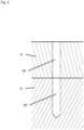
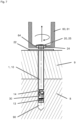
- FIGS. 4 to 9 show successive stages during installation and the subsequent implementation of a dismantling method according to the invention using an anchor 1 according to Figures 1 to 3 .
- a substrate 8 with an approximately cylindrical hole 90 and an attachment 9 are provided, the attachment 9 having an approximately cylindrical through opening 92 which is aligned with the hole 90 in the substrate 8.
- the anchor bolt 10 is inserted with its front end with the expansion area 13 first into the through opening 92 in the attachment 9 and driven into the hole 90 by applying axially forward forces, that is to say forces directed forward parallel to the longitudinal axis 99.
- the axially forward forces are applied to the head 20, for example by hitting a hammer.
- the installation tool 50 is used in order to apply the axially forward forces to the head 20, the in Figure 5 and in detail in Figure 10 shown installation tool 50 is used.
- the installation tool 50 has a receptacle 51 on the front for the head 20 of the anchor bolt 10.
- the head 20 of the anchor bolt 10 has an anchor radius R2 on its back, which is larger than a radius R1 of the installation tool 50 in the receptacle 51, the radius R1 expediently being able to extend over a significantly smaller radius R3.
- This configuration can make it possible to compensate for angular error ⁇ when installing the anchor 1 and speed up the installation process, as stated in Figure 5 is indicated.
- the anchor 1 is driven deep into the hole 90 until its head 20 rests directly on the attachment 9 or, as shown, via the optional washer 22.
- the resulting state is in Figure 6 shown.
- the anchor 1 and the attachment it holds 9 are now anchored to the substrate 8 by means of the expansion mechanism of the anchor 1, consisting of the expansion area 13 and the expansion body 30.
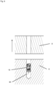
- FIGS. 7 to 9 show successive stages in carrying out a dismantling process according to the invention suitable for this purpose.
- a torque and preferably also a tensile force are applied to the anchor bolt 10 via its head 20.
- the torque is introduced via the driving profile 24 on the head 20, the tensile force is introduced at the collar 25 of the head 20.
- the tensile force has the result that the expansion area 13 is drawn deep into the expansion body 30, which causes the anchor bolt 10 to spin in the expansion body 30 and/or or counteracts a rotation of the expansion body 30 in the hole 90, and thus ensures that the front end region of the anchor bolt 10 is particularly reliably secured against rotation in the substrate 8.
- a predetermined breaking point for the breakage of the anchor bolt 10 in the method according to the invention is expediently arranged in such a way that the front anchor bolt fragment 18 remaining in the substrate 8 is short enough not to protrude from the substrate 8, that is to say that the anchor bolt fragment 18 is completely sunk into the hole 90 in the substrate 8 is.
- This makes it possible, among other things, to reassemble the previously dismantled part or another attachment in a particularly simple manner, with the hole 90 in the substrate 8 even being able to be used again for the reassembly.
- the predetermined breaking point for the breakage of the anchor bolt 10 in the method according to the invention is preferably in the neck area 14, where the anchor bolt 10 expediently has its smallest cross section, that is to say the anchor bolt 10 breaks in the dismantling method according to the invention preferably in the neck area 14.
- Such a target book point can be implemented with particularly little design effort, since the dimensioning of the neck region 14 to accommodate the expansion body 30 requires a comparatively small cross section in the neck region 14 anyway.
- dismantling tool 60 has claws 61, which, in particular at the end, each have a profile 64 that corresponds to the driving profile 24 of the head 20.
- the profiles 64 of the claws 61 are as in Figure 7 shown brought into contact with the driving profile 24, and the corresponding design from the profiles 64 to the driving profile 24 allows a positive torque transmission from the dismantling tool 60 to the head 20.
- the claws 61 engage with their profiles 64 in front of the collar 25, so that the profiles 64 rest axially on the collar 25, and a tensile force transmission from the disassembly tool 60 to the head 20 is possible.
- the dismantling tool 60 therefore engages at the bottom of the head 20 and then breaks the anchor bolt 10.
- the disassembly tool 60 preferably has a clutch 65, which on the one hand can be coupled to a rotating machine, for example a tangential impact wrench, and which on the other hand is coupled to the claws 61 in a rotationally fixed but axially displaceable manner.
- the dismantling tool 60 has a sleeve 66 in which the claws 61 are mounted so that they can move axially. Inlet slopes are formed between the sleeve 66 and the claws 61, which radially compress the claws 61 for gripping the anchor bolt 10, in particular the head 20, when the claws 61 are inserted into the sleeve 66.
- the expansion area 13 can be shaped to be non-round in cross section, for example elliptical or polygonal. This configuration prevents the anchor bolt 10 from spinning in the expansion body 30 even with comparatively low tensile forces.
- the neck area 14 can first be drawn to a scaled size and then compressed.
Landscapes
- Engineering & Computer Science (AREA)
- General Engineering & Computer Science (AREA)
- Mechanical Engineering (AREA)
- Joining Of Building Structures In Genera (AREA)
- Piles And Underground Anchors (AREA)
Description
- Die Erfindung betrifft ein Demontageverfahren für einen in einem Loch verankerten, als Spreizanker ausgeführten Anker, welcher einen Ankerbolzen und zumindest einen Spreizkörper aufweist, wobei am Ankerbolzen ein Spreizbereich für den Spreizkörper vorgesehen ist, wobei am Spreizbereich die Oberfläche des Ankerbolzens nach hinten hin konvergiert, und wobei der Spreizbereich den Spreizkörper bei Zug im Ankerbolzen radial verdrängt und den Anker hierbei verankert, gemäss dem Oberbegriff des Anspruchs 1. Die Erfindung betrifft ferner einen als Spreizanker ausgeführten Anker gemäss dem Oberbegriff des Anspruchs 6. Ein solcher Anker ist ausgebildet mit einem Ankerbolzen, welcher in einem rückwärtigen Bereich des Ankerbolzens einen Kopf aufweist, wobei der Kopf fest am Ankerbolzen angeordnet ist, und zumindest einem am Ankerbolzen angeordneten Spreizkörper, wobei der Ankerbolzen in einem vorderen Bereich des Ankerbolzens einen Spreizbereich für den Spreizkörper aufweist, wobei der Spreizbereich fest am Ankerbolzen angeordnet ist, wobei am Spreizbereich die Oberfläche des Ankerbolzens nach hinten hin konvergiert, und wobei der Spreizbereich den Spreizkörper bei Zug im Ankerbolzen radial verdrängt und den Anker hierbei verankert.
- Es sind, beispielsweise aus der
US 2016238051 A1 , Ankeranordnungen bekannt, bei denen ein Anbauteil mittels einer Mutter, die mit einem Spreizanker verschraubt ist, an einem Substrat gehalten ist. Bei der Montage einer solchen Anordnung wird zunächst der Anker in das Substrat eingesteckt. Durch anschliessendes Anziehen der Mutter am Spreizanker wird der Spreizanker vorgespannt und dabei der Spreizmechanismus des Ankers aktiviert und zugleich das Anbauteil am Substrat gesichert. Soll bei derartigen Spreizankern das Anbauteil wieder demontiert werden, so könnte die Ankermutter wieder abgeschraubt und das Anbauteil abgenommen werden. - Darüber hinaus sind, beispielsweise aus der
DE 102013112959 A1 , Spreizanker bekannt, welche einen fest mit dem Ankerbolzen des Spreizankers verbundenen Kopf aufweisen. Soll bei solchen Ankern das Anbauteil wieder demontiert, was beispielsweise erforderlich sein kann, wenn eine mit dem Anker bestigte Brandschutzplatte zu Wartungszwecken demontiert werden muss, ist dies nicht durch einfaches Lösen einer Schraubverbindung möglich. Daher schlägt dieDE 102013112959 A1 vor, den Kopf des Spreizankers mit einer Art Zange vom Ankerbolzen abzutrennen. - Die
DE 102010017722 A1 offenbart Spreizanker, bei denen der Ankerbolzen sowohl einen fest am Ankerbolzen angeordneten Kopf als auch ein Aussengewinde aufweist. Das Aussengewinde soll es ermöglichen, den Spreizanker durch Aufschrauben einer Mutter wiederzuverwenden, nachdem der Kopf zum Zwecke der Demontage des Anbauteils abgetrennt wurde. Das Abtrennen des Kopfes soll gemässDE 102010017722 A1 mittels eines Ankerbolzenschneiders oder eines Winkelschleifers erfolgen. Der Ankerbolzenschneider beziehungsweise der Winkelschleifer soll gemässDE 102010017722 A1 an einer speziell hierfür vorgesehenen Position am Anker angesetzt werden, welche so angeordnet ist, dass das Aussengewinde nach dem Abtrennen des Kopfes zugänglich wird. - Die
US 3512448 A beschreibt einen Spreizanker, der mittels eines Werkzeugs installiert wird, welches am Ankerbolzen zieht. Der Ankerbolzen weist eine ausserhalb des Bohrlochs liegende Schwächung auf, an welcher der Ankerbolzen reisst, wenn der Installationsvorgang abgeschlossen ist. Das Anbauteil wird durch ein eigenständiges Teil gehalten, welches während des Installationsvorgangs deformiert und in ringförmige Rillen am Ankerbolzen eingedrückt wird. - Die
US 2013097845 A1 zeigt einen Anker mit kopflosem Ankerbolzen, wobei der Verankerungsmechanismus des Ankers durch Aufbringen eines Drehmoments aktiviert wird. Um das Erreichen eines Sollzustandes des Verankerungsmechanismus anzuzeigen, weist der Anker eine Sollbruchstelle auf, die bei Erreichen eines Solldrehmoments während der Montage des Ankers bricht. Ein Demontageverfahren ist in derUS 2013097845 A1 nicht beschrieben. - Die
WO 2011009068 A1 zeigt eine Klemme zum Zusammenklemmen eines Werkstücks, wobei die Klemme einen Gewindebolzen und eine hierauf angeordnete Gewindehülse aufweist, die unter radialer Aufweitung gestaucht wird. Der Gewindebolzen weist eine geschwächte Region auf, an welcher der Gewindebolzen bei Rotation am Gewindebolzen brechen kann. - Die
GB1564237 A - Aufgabe der Erfindung ist es, ein Demontageverfahren für einen verankerten Anker und einen Anker anzugeben, welche bei geringem Aufwand eine besonders einfache, zuverlässige, sichere, für die Umgebung des Ankers schonende und vielzeitig einsetzbare Ankerdemontage ermöglichen.
- Die Aufgabe wird erfindungsgemäss durch ein Verfahren mit den Merkmalen des Anspruchs 1 sowie durch einen Anker mit den Merkmalen des Anspruchs 6 gelöst. Bevorzugte Ausführungsformen sind in den jeweils abhängigen Ansprüchen angegeben.
- Das erfindungsgemässe Demontageverfahren ist dadurch gekennzeichnet, dass auf den Ankerbolzen des im Loch verankerten Ankers ein Drehmoment und zugleich eine Zugkraft aufgebracht wird und der Ankerbolzen hierbei so weit belastet wird, bis er bricht.
- Ein Grundgedanke der Erfindung, auf dem sowohl das erfindungsgemässe Verfahren als auch der erfindungsgemässe Anker beruhen, kann darin gesehen werden, zur Demontage des Ankers und gegebenenfalls zur Demontage eines mit dem Anker verankerten Anbauteils den Ankerbolzen des Ankers gezielt mit einem hohen Drehmoment so zu beaufschlagen, dass der Anker am Ankerbolzen bricht. Insbesondere kann hierbei der Ankerbolzen in ein vorderes Ankerbolzenfragment und ein hiervon separates rückwärtiges Ankerbolzenfragment geteilt werden, und die Verankerung des vormals vom rückwärtigen Endbereich des Ankerbolzens gehaltenen Anbauteils aufgehoben werden. Das hintere Ankerbolzenfragment kann im Anschluss hieran entfernt werden, wohingegen das vordere Ankerbolzenfragment im Loch verbleiben kann. Insbesondere wird der Ankerbolzen also gezielt abgedreht, das heisst es wird gezielt ein Torsionsbruch erzeugt. Es hat sich gezeigt, dass hierdurch der Anker in besonders einfacher Weise besonders zuverlässig demontiert werden kann, wobei zugleich die Belastung für das Substrat und/oder das Anbauteil beim Demontieren besonders gering sein kann, was wiederum für eine anschliessende erneute Verankerung vorteilhaft sein kann, beispielsweise wenn das Anbauteil temporär für Inspektionszwecke abgenommen oder durch ein anderes Anbauteil ersetzt werden soll. Dies kann zum einen darin begründet liegen, dass erfindungsgemäss nicht mit scharfen Trennwerkzeugen am Ankerbolzen hantiert werden muss, und zum anderen darin, dass sich die beim Demontieren vorliegende Lastrichtung von der üblichen Lastrichtung des Ankers unterscheidet, so dass beispielsweise ein Ausbrechen des Substrats besonders einfach vermieden werden kann.
- Vor dem Demontieren ist der Anker, insbesondere an seiner Vorderseite, im Loch im Substrat verankert, wohingegen die Rückseite des Ankers vorzugsweise aus dem Loch im Substrat vorsteht und vorzugsweise das Anbauteil hält. Die Verankerung des Ankers ist in einem Verankerungsbereich des Ankers gegeben. Das Drehmoment wird zweckmässigerweise in einem rückwärtigen Bereich des Ankers, der in Längsrichtung des Ankers betrachtet hinter dem Verankerungsbereich des Ankers liegt, auf den Ankerbolzen aufgebracht. Das Loch ist in einem Substrat ausgebildet, vorzugsweise in einem Betonsubstrat. Insbesondere kann das Loch ein Sackloch sein, da das Demontageverfahren keinen Zugang zur Vorderseite des Ankers erfordert. Vorzugsweise ist das Loch ein Bohrloch und/oder mit einer zumindest annähernd zylindrischen Mantelfläche ausgebildet. Sofern ein Anbauteil vorgesehen ist, kann das Demontageverfahren auch zum Demontieren des vom Anker durchlaufenen und/oder vom Anker gehaltenen, insbesondere am Substrat gehaltenen, Anbauteils dienen. Mit dem Verfahren können aber auch Anker demontiert werden, die kein Anbauteil halten, und die beispielsweise versehentlich vorzeitig verankert wurden. Der Vektor des auf den Ankerbolzen aufgebrachten Drehmoments verläuft insbesondere in Richtung der Längsachse des Ankers und/oder des Ankerbolzens, das heisst der Ankerbolzen wird durch das Drehmoment um seine Längsachse tordiert. Sofern hier von der radialen Richtung, axialen Richtung oder Umfangsrichtung die Rede ist, soll sich dies insbesondere auf die Längsachse des Ankers und/oder des Ankerbolzens beziehen. Der Ankerbolzen besteht vorzugsweise aus einem Metallmaterial, insbesondere aus Stahl, und kann auch eine Beschichtung aufweisen. Die Begriffe vorne und hinten beziehungsweise rückwärtig sollen hier vorzugsweise einheitlich verwendet werden.
- Grundsätzlich könnte das erfindungsgemässe Verfahren eingesetzt werden, um Anker zu demontieren, welche fehlerhafterweise ohne Anbauteil installiert wurden. Besonders bevorzugt ist es jedoch, dass auf den Ankerbolzen des im Loch verankerten Ankers ein Drehmoment aufgebracht wird und der Ankerbolzen hierbei so weit belastet wird, bis er unter Aufhebung einer durch den Anker gegebenen Verankerung bricht. Insbesondere kann nach der Erfindung vorgesehen werden, dass auf den Ankerbolzen des im Loch verankerten Ankers ein Drehmoment aufgebracht wird und der Ankerbolzen hierbei so weit belastet wird, bis er bricht, und hierbei eine zuvor durch den Anker gegebene Verankerung eines Anbauteils an einem Substrat aufgehoben wird. Es wird also ein Anker gebrochen, der zuvor ein Anbauteil an einem Substrat verankert hat, und durch den Bruch wird die durch diesen Anker gegebene Verankerung des Anbauteils aufgehoben. Dieser vergleichsweise anspruchsvolle Demontagevorgang kann erfindungsgemäss besonders einfach realisiert werden. Das Anbauteil kann anschliessend, gegebenenfalls nach der Demontage eventuell vorhandener zusätzlicher Anker, vom Substrat abgenommen werden, wobei dieses Abnehmen auch als Teil des erfindungsgemässen Demontageverfahrens angesehen werden kann.
- Besonders zweckmässig ist es, dass auf den Ankerbolzen des im Loch verankerten Ankers ein Drehmoment aufgebracht wird und der Ankerbolzen hierbei so weit belastet wird, bis er innerhalb des Anbauteils oder des Substrats bricht, vorzugsweise innerhalb des Substrats. Dies kann die Demontage weiter vereinfachen.
- Insbesondere kann vorgesehen werden, dass auf den Ankerbolzen des im Loch verankerten Ankers ein Drehmoment aufgebracht wird und der Ankerbolzen hierbei so weit belastet wird, bis er innerhalb des Lochs bricht, insbesondere innerhalb des Lochs im Substrat. Da die Bruchstelle demgemäss im Inneren des Lochs, insbesondere innerhalb des Substrats, liegt, kann der Anker in besonders einfacher Weise ohne Überstand demontiert werden, was unter anderem eine anschliessende Neumontage eines Anbauteils an derselben Stelle erleichtern kann, da überstehende Ankerreste vermieden werden. Um einen Bruch innerhalb des Lochs besonders zuverlässig gezielt herbeiführen zu können, kann eine Sollbruchstelle vor dem Kopf des Ankerbolzens vorgesehen werden.
- Der beim erfindungsgemässen Verfahren verwendete Anker ist ein Spreizanker. Ein solcher Spreizanker weist zumindest einen Spreizkörper auf, und am Ankerbolzen ist, insbesondere in einem vorderen Bereich des Ankerbolzens, ein Spreizbereich für den Spreizkörper vorgesehen, welcher den Spreizkörper bei Zug im Ankerbolzen radial verdrängt und den Anker hierbei verankert. Der Spreizkörper kann vorzugsweise eine Spreizhülse sein, welche den Ankerbolzen zumindest bereichsweise umgibt. Am Spreizbereich, der für eine Spreizhülse vorzugsweise als Spreizkonus ausgebildet sein kann, kann die Oberfläche des Ankerbolzens nach hinten hin konvergieren. Vorzugsweise ist der Spreizanker einer vom Typ "kraftkontrollierter Spreizanker".
- Zweckmässigerweise bildet der Verankerungsbereich des Ankers, also der Bereich, in welchem der Anker im Bohrloch verankert ist, ein Wiederlager, so dass der Ankerbolzen beim Aufbringen des Drehmoments zur Demontage hinter dem Verankerungsbereich brechen kann. Bei einem Spreizanker wird der Verankerungsbereich des Ankers und somit das Widerlager durch den Spreizkörper und den Spreizbereich gebildet.
- In dem erfindungsgemässen Verfahren wird auf den Ankerbolzen des im Loch verankerten Ankers ein Drehmoment und zugleich eine Zugkraft aufgebracht und der Ankerbolzen hierbei so weit belastet, bis er bricht, insbesondere innerhalb des Lochs bricht. Demgemäss wird der Ankerbolzen bei der Demontage zugleich auf Drehung und auf Zug belastet. Dies kann insbesondere im Hinblick auf die Ausführung als Spreizanker vorteilhaft sein. Denn durch die zusätzliche Zugkraft wird der Spreizmechanismus besonders fest verankert, und einem unerwünschten Durchdrehen des Ankerbolzens kann in einfacher Weise besonders wirksam entgegengewirkt werden, so dass am Verankerungsbereich ein besonders zuverlässiges Wiederlager gegeben ist und der Ankerbolzen besonders zuverlässig bricht. Die Zugkraft ist insbesondere nach hinten gerichtete, also insbesondere in der Richtung, die vom Verankerungsbereich zum Kopf des Ankers weist.
- Für ein besonders festes Widerlager bei einem Spreizanker kann alternativ oder zusätzlich eine drehfeste Kopplung zwischen Ankerbolzen und Spreizkörper, insbesondere zwischen Ankerbolzen und Spreizhülse, vorgesehen sein. Die drehfeste Kopplung kann beispielsweise durch eine unrunde Querschnittsform des Ankerbolzens am Spreizbereich oder/und durch eine Nase am Ankerbolzen, die radial in die Spreizhülse vorsteht, gebildet sein.
- Eine besonders zweckmässige Ausgestaltung liegt darin, dass der Ankerbolzen einen Kopf aufweist ist, und dass das Drehmoment auf den Kopf des Ankerbolzens aufgebracht wird. Insbesondere kann vorgesehen sein, dass zum Aufbringen des Drehmoments ein Demontagewerkzeug am Kopf angesetzt wird. Eine Drehmomenteinleitung auf den Kopf ist, bei besonders einfachem Aufbau des Ankers, in besonders einfacher und schonender Weise möglich. Der Kopf des Ankerbolzens bildet zweckmässigerweise ein globales Querschnittsmaximum des Ankerbolzens, das heisst am Kopf weist der Ankerbolzen seinen grössten Querschnitt auf. Insbesondere kann der Kopf eine Auflagefläche für das Anbauteil bilden, mit welcher das Anbauteil unmittelbar oder mittelbar, beispielsweise über eine Unterlegscheibe, formschlüssig gesichert werden kann. Vorzugsweise kann der Kopf in einem rückwärtigen Endbereich des Ankerbolzens, vorzugsweise am rückwärtigen Ende des Ankerbolzens, angeordnet sein. Insbesondere kann vorgesehen sein, dass der Ankerbolzen im Demontageverfahren so weit belastet wird, bis er vor dem Kopf bricht, und dass er insbesondere so weit belastet wird, bis er zwischen dem Kopf und dem Spreizbereich ist, bricht.
- Es ist vorgesehen, dass der Spreizbereich und der Kopf fest am Ankerbolzen angeordnet sind. Insbesondere ist es vorteilhaft, dass der Spreizbereich des Ankerbolzens fest mit dem Kopf des Ankerbolzens verbunden ist, was einen besonders definierten Spannungszustand beim Demontagevorgang und somit eine besonders zuverlässige Demontage ermöglicht. Zweckmässigerweise ist hierzu der Ankerbolzen, insbesondere einschliesslich seines Kopfs und seines Spreizbereichs, monolithisch, das heisst ohne Fügestellen, ausgebildet, was eine feste Verbindung bei besonders geringem Herstellungsaufwand erlaubt. Unter einer festen Verbindung kann insbesondere eine Verbindung verstanden werden, welche nicht zerstörungsfrei lösbar ist.
- Vorzugsweise wird das Drehmoment, und gegebenenfalls auch die Zugkraft, mittels eines Demontagewerkzeugs auf den Ankerbolzen, insbesondere auf dessen Kopf aufgebracht. Ein solches Demontagewerkzeugs kann beispielsweise Klauen aufweisen, welche den Kopf, vorzugsweise zum Aufbringen der Zugkraft, umgreifen, wobei die Klauen über ein Profil verfügen, welches zur Drehmomentübertragung in ein korrespondierendes Mitnahmeprofil am Ankerbolzen, insbesondere an dessen Kopf, eingreift.
- Ein erfindungsgemässer Anker ist ausgestattet mit einem Ankerbolzen, welcher in einem rückwärtigen Bereich des Ankerbolzens einen Kopf aufweist, und zumindest einem am Ankerbolzen angeordneten Spreizkörper, welcher vorzugsweise als den Ankerbolzen umgebende Spreizhülse ausgebildet ist, wobei der Ankerbolzen in einem vorderen Bereich des Ankerbolzens einen Spreizbereich für den Spreizkörper aufweist. Der Anker ist also als Spreizanker ausgeführt. Er zeichnet sich dadurch aus, dass der Ankerbolzen ein Mitnahmeprofil zum Aufbringen eines Drehmoments auf dem Ankerbolzen aufweist, dass das Mitnahmeprofil am Kopf angeordnet ist, und dass der Kopf einen das Mitnahmeprofil überragenden Bund aufweist, der sich rückwärtig an das Mitnahmeprofil anschliesst. Über dieses Mitnahmeprofil kann, bei geringem Herstellungsaufwand, in besonders einfacher Weise ein Drehmoment auf den Anker aufgebracht werden, insbesondere zum Zwecke der Demontage des Ankers. Im Detail kann der Anker wie schon weiter oben im Zusammenhang mit dem Verfahren erläutert ausgeführt sein. Der Kopf ist vorzugsweise fest am Ankerbolzen angeordnet und besonders bevorzugt monolithisch, das heisst ohne Fügestellen, mit dem Ankerbolzen ausgeführt.
- Das Mitnahmeprofil kann vorzugsweise ein Aussenmehrkantprofil sein, welches zweckmässigerweise umfangsseitig am Ankerbolzen angeordnet ist. Beispielsweise kann das Aussenmehrkantprofil eine Aussenverzahnung sein. Hierdurch ist bei besonders geringem Herstellungsaufwand eine besonders zuverlässige Drehmomentübertragung möglich.
- Erfindungsgemäss ist das Mitnahmeprofil am Kopf angeordnet, wo es bei besonders geringem Herstellungsaufwand besonders gut zugänglich ist. Grundsätzlich könnte das Mitnahmeprofil auch dem Kopf vorgelagert sein.
- Zweckmässigerweise erstreckt sich das Mitnahmeprofil in Axialrichtung nur über ein Teil des Kopfs. Hierdurch können in Axialrichtung eine oder mehrere Stufen gebildet werden, welche zur Zugkrafteinleitung beim Demontageverfahren dienen können. Erfindungsgemäss weist der Kopf einen das Mitnahmeprofil, insbesondere radial, überragenden Bund auf, der sich rückwärtig an das Mitnahmeprofil anschliesst. Gemäss diesem Erfindungsgedanken ist der Kopf an dem hinter dem Mitnahmeprofil angeordneten Bund zumindest bereichsweise querschnittsgrösser als am Mitnahmeprofil. Ein solcher Bund kann zum einen das Mitnahmeprofil abdecken und somit beispielsweise Beschädigungen an dem Mitnahmeprofil oder durch das Mitnahmeprofil in herstellungstechnisch besonders einfacher Weise entgegenwirken. Zum anderen kann am Bund eine Stufe zur Zugkrafteinleitung beim Demontageverfahren gebildet sein.
- Es kann vorgesehen werden, dass der Kopf unmittelbar auf dem zu befestigenden Anbauteil zur Auflage kommt. Besonders bevorzugt ist es jedoch, dass der Anker eine Unterlegscheibe aufweist, welche den Ankerbolzen umgibt. Hierdurch kann der Anker auch zur Verankerung von vergleichsweise weichen Platten verwendet werden. Der Ankerbolzen liegt dann mit seinem Kopf auf der Unterlegscheibe auf, welche wiederum auf dem Anbauteil aufliegt, das heisst der Kopf kommt mittelbar auf dem Anbauteil zur Auflage. Die Unterlegscheibe umgibt den Ankerbolzen ringförmig, vorzugsweise geschlossen ringförmig und weist einen Durchgang auf, durch den der Ankerbolzen durchtritt. Zweckmässigerweise ist sie ein vom Ankerbolzen separates Teil.
- Beim Demontageverfahren wird das Drehmoment und/oder die Zugkraft vorzugsweise hinter der Unterlegscheibe auf den Ankerbolzen aufgebracht, das heisst auf der dem Spreizkörper und/oder dem Spreizbereich abgewandten Seite der Unterlegscheibe, da dieser Bereich besonders gut zugänglich ist. Das Mitnahmeprofil ist vorzugsweise, insbesondere in axialer Richtung, zwischen dem Bund und der Unterlegscheibe angeordnet ist, so dass eine besonders gute Zugänglichkeit des Mitnahmeprofils gegeben ist.
- Zweckmässigerweise ist die Sollbruchstelle für einen Torsionsbruch des Ankerbolzens, also die Stelle, an welcher der Ankerbolzen bei der Demontage in die beiden Ankerbolzenfragmente zerbricht, und/oder das globale Querschnittsminimum des Ankerbolzens relativ weit vorne am Ankerbolzen und somit bei installiertem Anker tief angeordnet. Das vordere Ankerbolzenfragment kann dann entsprechend kurz sein. Insbesondere kann vorgesehen sein, dass ein Grossteil des Lochs nach der Demontage zur erneuten Installation eines Ankers zur Verfügung steht, was eine besonders einfache Neuinstallation ermöglicht. Demgemäss ist es besonders bevorzugt, dass die Sollbruchstelle für einen Torsionsbruch des Ankerbolzens und/oder das globale Querschnittsminimum des Ankerbolzens in der vorderen Hälfte, insbesondere im vorderen Drittel des Ankerbolzens angeordnet ist.
- Besonders zweckmässig ist es, dass der Ankerbolzen einen Halsbereich zur Aufnahme des Spreizkörpers, insbesondere der Spreizhülse, aufweist, wobei am Halsbereich ein, insbesondere globales, Querschnittsminimum des Ankerbolzens gegeben ist. Insbesondere kann der Halsbereich in vorteilhafter Weise eine Doppelfunktion innehaben: Er kann einerseits den Spreizkörper vor dem Spreizvorgang aufnehmen und kann andererseits in besonders einfacher Weise die Sollbruchstelle für einen Torsionsbruch des Ankerbolzens definieren, wobei letzteres durch Kerbwirkung unterstützt werden kann. Da sich der Halsbereich an den Spreizbereich anschliesst, kann die Sollbruchstelle dabei in konstruktiv besonders einfacher Weise weit vorne am Ankerbolzen angeordnet werden, was die zuvor erläuterten Vorteile beinhaltet. Wenn der Spreizkörper eine Spreizhülse ist, kann der Halsbereich zweckmässigerweise eine ringförmige Einschnürung des Bolzens sein.
- Vorteilhafterweise wird in einem erfindungsgemässen Verfahren als Anker ein erfindungsgemässer Anker eingesetzt. Merkmale, die im Zusammenhang mit dem erfindungsgemässen Verfahren erläutert werden, können auch beim erfindungsgemässen Anker zum Einsatz kommen, so wie auch umgekehrt Merkmale, die im Zusammenhang mit dem erfindungsgemässen Anker erläutert werden, auch beim erfindungsgemässen Verfahren zum Einsatz kommen können. Das Anbauteil kann insbesondere eine Brandschutzplatte sein, welche mittels des Ankers beispielsweise an einem Tübbing in einem Tunnel verankert ist. Es kann erforderlich sein, solche Brandschutzplatten zu Prüf-, Revisions- oder Wartungszwecken zu entfernen. Hierzu kann das erfindungsgemässe Verfahren zum Einsatz kommen.
- Die Erfindung wird nachfolgend anhand bevorzugter Ausführungsbeispiele näher erläutert, die schematisch in den beiliegenden Figuren dargestellt sind. In den Figuren zeigen schematisch:
- Figur 1:
- eine perspektivische Darstellung eines Ausführungsbeispiels eines erfindungsgemässen Ankers;
- Figur 2:
- eine Seitenansicht des Ankers aus
Figur 1 ; - Figur 3:
- eine Seitenansicht des Ankerbolzens des Ankers aus
Figur 1 und Figur 2 ; - Figuren 4 bis 6:
- aufeinander folgende Stadien bei der Installation des Ankerbolzens der
Figuren 1 bis 3 ; - Figuren 7 bis 9:
- aufeinander folgende Stadien der Demontage des installierten Ankerbolzens der
Figuren 1 bis 3 im Rahmen eines erfindungsgemässen Verfahrens; - Figur 10:
- eine vergrösserte Ansicht des Installationswerkzeugs aus
Figur 5 und des Kopfes des Ankers; und - Figur 11:
- eine Detailansicht des in
Figur 7 nur grob schematisch dargestellten Demontagewerkzeugs. - Die
Figuren 1 bis 3 zeigen ein erstes Ausführungsbeispiel eines erfindungsgemässen Ankers 1. Der Anker 1 ist als Spreizanker ausgeführt und weist einen länglichen Ankerbolzen 10 und einen als Spreizhülse ausgeführten Spreizkörper 30 auf, welcher den Ankerbolzen 10 ringartig umgibt. In einem entlang der Längsachse 99 des Ankerbolzens 10 vorderen Endbereich weist der Ankerbolzen 10 einen Halsbereich 14 und daran vorderseitig anschliessend einen Spreizbereich 13 auf. Im Halsbereich 14 weist der Ankerbolzen 10 sein globales Querschnittsminimum auf, das heisst dort ist sein Querschnitt am kleinsten. Der als Spreizhülse ausgeführte Spreizkörper 30 ist in diesem Halsbereich 14 aufgenommen. Im Spreizbereich 13 nimmt der Querschnitt des Ankerbolzens 10 nach vorne hin wieder zu, das heisst im Spreizbereich 13 konvergiert der Ankerbolzen 10 nach hinten hin. Beim Verankern des Ankers 1 läuft der Spreizkörper 30 auf den Spreizbereich 13 des Ankerbolzens 10 auf und wird hierbei radial gespreizt. - Der Ankerbolzen 10 weist ferner einen Kopf 20 auf, der am entlang der Längsachse 99 hinteren Ende des Ankerbolzens 10 angeordnet ist. Am Kopf 20 weist der Ankerbolzen 10 sein globales Querschnittsmaximum auf, das heisst dort ist sein Querschnitt am grössten. Der Kopf 20 des Ankerbolzens 10 weist an seiner Vorderseite einen Bereich mit einem Mitnahmeprofil 24 auf, wobei das Mitnahmeprofil 24 hier beispielhaft als Aussensechskantprofil ausgeführt ist. Das Mitnahmeprofil 24 dient zum Aufbringen eines Drehmoments von einem Demontagewerkzeug 60 auf den Ankerbolzen 10. Rückseitig am Mitnahmeprofil 24 weist der Kopf 20 einem ringförmigen Bund 25 auf. Dieser Bund 25 steht in radialer Richtung über das Mitnahmeprofil 24 über. Somit ist zwischen dem Mitnahmeprofil 24 und dem Bund 25 eine axiale Stufe gebildet, an denen das Demontagewerkzeug 60 zum Aufbringen einer nach hinten gerichteten Zugkraft auf den Ankerbolzen 10 angreifen kann.
- Im dargestellten Ausführungsbeispiel weist der Anker 1 auch eine Unterlegscheibe 22 auf, welche den Ankerbolzen 10 in Form eines Rings umgibt. Die Durchgangsöffnung in der Unterlegscheibe 22, durch die der Ankerbolzen 10 hindurchtritt, ist querschnittskleiner als der Kopf 20, so dass eine Axialkrafteinleitung vom Kopf 20 auf ein zu befestigendes Anbauteil 9 mittelbar über die Unterlegscheibe 22 erfolgen kann. Die Unterlegscheibe 22 ist vorzugsweise ein vom Ankerbolzen 10 separates Bauteil. Die Unterlegscheibe 22 kann jedoch fakultativ sein, und es ist auch denkbar, dass der Kopf 20 unmittelbar am Anbauteil 9 zur Auflage kommt.
- Die
Figuren 4 bis 9 zeigen aufeinanderfolgende Stadien beim Installieren und der anschliessenden Durchführung eines erfindungsgemässen Demontageverfahrens unter Verwendung eines Ankers 1 gemässFiguren 1 bis 3 . - Zunächst werden, wie in
Figur 4 dargestellt, ein Substrat 8 mit einem etwa zylindrischen Loch 90 sowie ein Anbauteil 9 bereitgestellt, wobei das Anbauteil 9 eine etwa zylindrische Durchgangsöffnung 92 aufweist, welche mit dem Loch 90 im Substrat 8 fluchtet. - Sodann wird, wie in
Figur 5 dargestellt, der Ankerbolzen 10 mit seinem vorderen Ende mit dem Spreizbereich 13 voran in die Durchgangsöffnung 92 im Anbauteil 9 eingeführt und durch Aufbringen von axial nach vorne gerichteten Kräften, das heisst parallel zur Längsachse 99 nach vorne gerichteten Kräfte, in das Loch 90 eingetrieben. Vorzugsweise werden die axial nach vorne gerichteten Kräfte auf den Kopf 20 aufgebracht, beispielsweise mittels Schlägen eines Hammers. Besonders bevorzugt ist es, dass zum Aufbringen der axial nach vorne gerichteten Kräfte auf den Kopf 20 das inFigur 5 und im Detail inFigur 10 dargestellt Installationswerkzeug 50 verwendet wird. Wie insbesondereFigur 10 zeigt, weist das Installationswerkzeug 50 vorderseitig eine Aufnahme 51 für den Kopf 20 des Ankerbolzens 10 auf. Insbesondere kann vorgesehen sein, dass der Kopf 20 des Ankerbolzens 10 an seiner Rückseite einen Ankerradius R2 aufweist, welcher grösser ist als ein Radius R1 des Installationswerkzeugs 50 in der Aufnahme 51, wobei der Radius R1 zweckmässigerweise über einen deutlich kleineren Radius R3 auslaufen kann. Diese Konfiguration kann es ermöglichen, bei der Installation des Ankers 1 Winkelfehler α zu kompensieren und den Installationsvorgang zu beschleunigen, wie es inFigur 5 angedeutet ist. - Der Anker 1 wird so tief in das Loch 90 eingetrieben, bis sein Kopf 20 unmittelbar, oder, wie dargestellt, über die fakultativ vorhandenen Unterlegscheibe 22, auf dem Anbauteil 9 anliegt. Der resultierende Zustand ist in
Figur 6 gezeigt. Der Anker 1 und das von ihm gehaltene Anbauteil 9 sind nun mittels Spreizmechanismus des Ankers 1, bestehend aus Spreizbereich 13 und Spreizkörper 30, am Substrat 8 verankert. - Beispielsweise zum Zwecke des Austauschs eines beschädigten Anbauteils 9 oder zum Zwecke der Inspektion des unter dem Anbauteil 9 liegenden Substrats 8 oder aus anderen Gründen kann es erforderlich werden, die Verankerung wieder zu lösen. Die
Figuren 7 bis 9 zeigen aufeinanderfolgende Stadien bei der Durchführung eines hierfür geeigneten erfindungsgemässen Demontageverfahrens. - Wie in
Figur 7 mit Pfeilen angedeutet ist, wird auf den Ankerbolzen 10 über dessen Kopf 20 ein Drehmoment und vorzugsweise zugleich auch eine Zugkraft aufgebracht. Die Drehmomenteinleitung erfolgt dabei über das Mitnahmeprofil 24 am Kopf 20, die Zugkrafteinleitung am Bund 25 des Kopfes 20. Die Zugkraft hat zur Folge, dass der Spreizbereich 13 tief in den Spreizkörper 30 eingezogen wird, was einem Durchdrehen des Ankerbolzens 10 im Spreizkörper 30 und/oder einem Durchdrehen des Spreizkörpers 30 im Loch 90 entgegenwirkt, und somit dafür sorgt, dass der vordere Endbereich des Ankerbolzens 10 besonders zuverlässig drehfest im Substrat 8 festliegt. Das am Kopf 20 und somit am hinteren Ende des Ankerbolzens 10 aufgebrachte Drehmoment tordiert den vorderseitig drehfest im Substrat 8 festliegende Ankerbolzen 10 so weit, dass es zum kontrollierten Bruch des Ankerbolzens 10 in ein vorderes Ankerbolzenfragment 18 mit zumindest einem Teil des Spreizbereichs 13 und in ein hinteres Ankerbolzenfragment 19 mit dem Kopf 20 kommt, das heisst der Ankerbolzen 10 wird bei der Demontage zerstört. Der resultierende Zustand ist inFigur 8 dargestellt. Nun kann, nachdem gegebenenfalls noch vorhandene weitere Anker gelöst wurden, das Anbauteil 9 wie inFigur 9 mit einem Pfeil angedeutet vom Substrat 8 abgehoben und entfernt werden. Das vordere Ankerbolzenfragment 18 bleibt dabei im Substrat 8 zurück. - Zweckmässigerweise ist eine Sollbruchstelle für den Bruch des Ankerbolzens 10 im erfindungsgemässe Verfahren derart angeordnet, dass das im Substrat 8 zurückbleibende vordere Ankerbolzenfragment 18 kurz genug ist, um nicht am Substrat 8 vorzustehen, das heisst dass das Ankerbolzenfragment 18 vollständig im Loch 90 im Substrat 8 versenkt ist. Dies ermöglicht unter anderem in besonders einfacher Weise eine erneute Montage des zuvor demontierten oder eines anderen Anbauteils, wobei für die erneute Montage unter Umständen sogar das Loch 90 im Substrat 8 abermals verwendet werden kann. Wie ein Vergleich des
Figuren 7 und8 zeigt, befindet sich die Sollbruchstelle für den Bruch des Ankerbolzens 10 im erfindungsgemässe Verfahren vorzugsweise im Halsbereich 14, wo der Ankerbolzen 10 zweckmässigerweise seinen kleinsten Querschnitt aufweist, das heisst der Ankerbolzen 10 bricht im erfindungsgemässen Demontageverfahren vorzugsweise im Halsbereich 14. - Eine solche Sollbuchstelle kann mit besonders geringem konstruktiven Aufwand realisiert werden, da die Dimensionierung des Halsbereichs 14 zur Aufnahme des Spreizkörper 30 ohnehin einen vergleichsweise geringen Querschnitt im Halsbereich 14 erfordert.
- Zum Aufbringen des Drehmoments und vorzugsweise auch der Zugkraft auf den Kopf 20 kann insbesondere ein, grob schematisch in
Figur 7 und im Detail inFigur 11 dargestelltes, Demontagewerkzeug 60 verwendet werden. Im dargestellten Ausführungsbeispiel weist das Demontagewerkzeug 60 Klauen 61 auf, die, insbesondere endseitig, jeweils ein Profil 64 aufweisen, das mit dem Mitnahmeprofil 24 des Kopfs 20 korrespondiert. Die Profile 64 der Klauen 61 werden wie inFigur 7 gezeigt am Mitnahmeprofil 24 zur Anlage gebracht, und die korrespondierende Ausgestaltung von den Profilen 64 zum Mitnahmeprofil 24 erlaubt eine formschlüssige Drehmomentübertragung vom Demontagewerkzeug 60 auf den Kopf 20. Dabei greifen die Klauen 61 mit ihren Profilen 64 vor dem Bund 25 ein, so dass die Profile 64 axial am Bund 25 anliegen, und eine Zugkraftübertragung vom Demontagewerkzeug 60 auf den Kopf 20 möglich ist. Das Demontagewerkzeug 60 greift also unten am Kopf 20 ein und zerbricht dann den Ankerbolzen 10. - Wie insbesondere
Figur 11 zeigt weist das Demontagewerkzeug 60 vorzugsweise eine Kupplung 65 auf, welche einerseits mit einer drehenden Maschine, beispielsweise einem Tangential-Schlagschrauber, gekoppelt werden kann, und welche andererseits mit den Klauen 61 drehfest, aber axial verschiebbar, gekoppelt ist. Ferner weist das Demontagewerkzeug 60 eine Hülse 66 auf, in welcher die Klauen 61 axial verschiebbar gelagert sind. Zwischen der Hülse 66 und den Klauen 61 sind Einlaufschrägen gebildet, welche die Klauen 61 zum Greifen des Ankerbolzens 10, insbesondere des Kopfs 20, radial zusammendrängen, wenn die Klauen 61 in die Hülse 66 eingeschoben werden. - Um die Zugkraft auf das Anbauteil 9 beim Demontageverfahren zu reduzieren, was insbesondere zur Verringerung des Drucks auf das Anbauteil 9 dann vorteilhaft sein kann, wenn das Anbauteil 9 wiederverwendet werden soll, kann der Spreizbereich 13 im Querschnitt unrund, beispielsweise elliptisch oder polygonförmig ausgeformt werden. Durch diese Ausgestaltung wird ein Durchdrehen des Ankerbolzens 10 im Spreizkörper 30 schon bei vergleichsweise geringen Zugkräften gehemmt. Zur Herstellung eines entsprechenden Ankerbolzens 10 kann zunächst der Halsbereich 14 in skalierter Grösse gezogen und anschliessend aufgestaucht werden.
Claims (11)
- Demontageverfahren für einen in einem Loch (90) verankerten, als Spreizanker ausgeführten Anker (1), welcher einen Ankerbolzen (10), und zumindest einen Spreizkörper (30) aufweist, wobei am Ankerbolzen (10) ein Spreizbereich (13) für den Spreizkörper (30) vorgesehen ist, wobei am Spreizbereich (13) die Oberfläche des Ankerbolzens (10) nach hinten hin konvergiert, und wobei der Spreizbereich (13) den Spreizkörper (30) bei Zug im Ankerbolzen (10) radial verdrängt und den Anker (1) hierbei verankert,
dadurch gekennzeichnet,
dass im Demontageverfahren auf den Ankerbolzen (10) des im Loch (90) verankerten Ankers (1) ein Drehmoment und zugleich eine Zugkraft aufgebracht wird und der Ankerbolzen (10) hierbei so weit belastet wird, bis er bricht. - Verfahren nach Anspruch 1,
dadurch gekennzeichnet,
dass auf den Ankerbolzen (10) des im Loch (90) verankerten Ankers (1) ein Drehmoment aufgebracht wird und der Ankerbolzen (10) hierbei so weit belastet wird, bis er bricht, und hierbei eine zuvor durch den Anker (1) gegebene Verankerung eines Anbauteils (9) an einem Substrat (8) aufgehoben wird. - Verfahren nach einem der vorstehenden Ansprüche,
dadurch gekennzeichnet,
dass auf den Ankerbolzen (10) des im Loch (90) verankerten Ankers (1) ein Drehmoment aufgebracht wird und der Ankerbolzen (10) hierbei so weit belastet wird, bis er innerhalb des Lochs (90) bricht. - Verfahren nach einem der vorstehenden Ansprüche,
dadurch gekennzeichnet,
dass der Ankerbolzen (10) einen Kopf (20) aufweist ist, und dass das Drehmoment auf den Kopf (20) des Ankerbolzens (10) aufgebracht wird. - Verfahren nach einem der vorstehenden Ansprüche,
dadurch gekennzeichnet,
dass das Drehmoment mittels eines Demontagewerkzeugs (60) auf den Ankerbolzen (10) aufgebracht wird. - Als Spreizanker ausgeführter Anker (1) mit- einem Ankerbolzen (10), welcher in einem rückwärtigen Bereich des Ankerbolzens (10) einen Kopf (20) aufweist, wobei der Kopf (20) fest am Ankerbolzen (10) angeordnet ist, und- zumindest einem am Ankerbolzen (10) angeordneten Spreizkörper (30),- wobei der Ankerbolzen (10) in einem vorderen Bereich des Ankerbolzens (10) einen Spreizbereich (13) für den Spreizkörper (30) aufweist, wobei der Spreizbereich (13) fest am Ankerbolzen (10) angeordnet ist, wobei am Spreizbereich (13) die Oberfläche des Ankerbolzens (10) nach hinten hin konvergiert, und wobei der Spreizbereich (13) den Spreizkörper (30) bei Zug im Ankerbolzen (10) radial verdrängt und den Anker (1) hierbei verankert,dadurch gekennzeichnet,dass der Ankerbolzen (10) ein Mitnahmeprofil (24) zum Aufbringen eines Drehmoments auf dem Ankerbolzen (10) aufweist,dass das Mitnahmeprofil (24) am Kopf (20) angeordnet ist, unddass der Kopf (20) einen das Mitnahmeprofil (24) überragenden Bund (25) aufweist, der sich rückwärtig an das Mitnahmeprofil (24) anschliesst.
- Anker (1) nach Anspruch 6,
dadurch gekennzeichnet,
dass das Mitnahmeprofil (24) ein Aussenmehrkantprofil ist. - Anker (1) nach einem der Ansprüche 6 oder 7,
dadurch gekennzeichnet,
dass er eine Unterlegscheibe (22) aufweist, welche den Ankerbolzen (10) umgibt. - Anker (1) nach Anspruch 8,
dadurch gekennzeichnet,
dass das Mitnahmeprofil (24) zwischen dem Bund (25) und der Unterlegscheibe (22) angeordnet ist. - Anker (1) nach einem der Ansprüche 6 bis 9,
dadurch gekennzeichnet,
dass der Ankerbolzen (10) einen Halsbereich (14) zur Aufnahme des Spreizkörpers (30) aufweist, wobei am Halsbereich (14) ein Querschnittsminimum des Ankerbolzens (10) gegeben ist. - Verfahren nach einem der der Ansprüche 1 bis 5,
dadurch gekennzeichnet,
dass als Anker (1) ein Anker (1) nach einem der Ansprüche 6 bis 10 eingesetzt wird.
Applications Claiming Priority (2)
| Application Number | Priority Date | Filing Date | Title |
|---|---|---|---|
| EP17159523.4A EP3372847A1 (de) | 2017-03-07 | 2017-03-07 | Spreizanker und verfahren zum demontieren eines spreizankers |
| PCT/EP2018/054738 WO2018162275A1 (de) | 2017-03-07 | 2018-02-27 | Spreizanker und verfahren zum demontieren eines spreizankers |
Publications (3)
| Publication Number | Publication Date |
|---|---|
| EP3592994A1 EP3592994A1 (de) | 2020-01-15 |
| EP3592994C0 EP3592994C0 (de) | 2023-11-29 |
| EP3592994B1 true EP3592994B1 (de) | 2023-11-29 |
Family
ID=58264437
Family Applications (2)
| Application Number | Title | Priority Date | Filing Date |
|---|---|---|---|
| EP17159523.4A Withdrawn EP3372847A1 (de) | 2017-03-07 | 2017-03-07 | Spreizanker und verfahren zum demontieren eines spreizankers |
| EP18707369.7A Active EP3592994B1 (de) | 2017-03-07 | 2018-02-27 | Spreizanker und verfahren zum demontieren eines spreizankers |
Family Applications Before (1)
| Application Number | Title | Priority Date | Filing Date |
|---|---|---|---|
| EP17159523.4A Withdrawn EP3372847A1 (de) | 2017-03-07 | 2017-03-07 | Spreizanker und verfahren zum demontieren eines spreizankers |
Country Status (6)
| Country | Link |
|---|---|
| US (1) | US11655843B2 (de) |
| EP (2) | EP3372847A1 (de) |
| AU (1) | AU2018231326B2 (de) |
| ES (1) | ES2966360T3 (de) |
| MY (1) | MY201175A (de) |
| WO (1) | WO2018162275A1 (de) |
Citations (1)
| Publication number | Priority date | Publication date | Assignee | Title |
|---|---|---|---|---|
| GB1564237A (en) * | 1976-08-09 | 1980-04-02 | Hilti Ag | Expansible dowel |
Family Cites Families (16)
| Publication number | Priority date | Publication date | Assignee | Title |
|---|---|---|---|---|
| GB1170762A (en) | 1966-02-25 | 1969-11-19 | Avdel Ltd | Masonry anchor |
| US3577825A (en) * | 1967-11-30 | 1971-05-04 | Republic Steel Corp | Bolt anchor and method for making same |
| US4613264A (en) * | 1982-04-16 | 1986-09-23 | Mcintyre Douglas O | Anchor bolt |
| US4764055A (en) * | 1986-10-02 | 1988-08-16 | Birmingham Bolt Company, Inc. | Resin reinforced expansion anchor system |
| US5228250A (en) * | 1992-08-03 | 1993-07-20 | Kesselman David A | Tamper proof anchor bolt assembly |
| US5203647A (en) * | 1991-12-16 | 1993-04-20 | Russell Blackwell | Roof bolt anchor |
| DE19712784C2 (de) * | 1997-03-26 | 1999-02-11 | Sfs Ind Holding Ag | Schraube |
| DE102005022655A1 (de) * | 2004-05-11 | 2006-11-23 | Brückl-Gesellschaft für Befestigungssysteme mbH | Spreizdübel |
| WO2011009068A1 (en) * | 2009-07-17 | 2011-01-20 | Monogram Aerospace Fasteners, Inc. | Low profile dual-action disposable clamp |
| US8192122B2 (en) * | 2009-08-17 | 2012-06-05 | Powers Fasteners, Inc. | Anchor bolt |
| DE102010017722A1 (de) | 2009-08-22 | 2011-03-03 | Fischerwerke Gmbh & Co. Kg | Befestigungselement und Verfahren zur Befestigung eines Gegenstandes |
| DE102011007570A1 (de) | 2011-04-18 | 2012-10-18 | Hilti Aktiengesellschaft | Spreizdübel |
| DE102013206388A1 (de) * | 2013-04-11 | 2014-10-16 | Hilti Aktiengesellschaft | Anker mit Spreizbereich und Schneidgewinde |
| EP2848826A1 (de) | 2013-09-16 | 2015-03-18 | HILTI Aktiengesellschaft | Spreizanker |
| DE102013112959A1 (de) | 2013-11-25 | 2015-05-28 | Fischerwerke Gmbh & Co. Kg | Werkzeug, System und Verfahren zum Abtrennen eines Kopfs von einem Schaft |
| US10422367B2 (en) * | 2016-12-12 | 2019-09-24 | Caterpillar Inc. | Shearing fastener for sealing a fastener hold |
-
2017
- 2017-03-07 EP EP17159523.4A patent/EP3372847A1/de not_active Withdrawn
-
2018
- 2018-02-27 AU AU2018231326A patent/AU2018231326B2/en active Active
- 2018-02-27 MY MYPI2019004034A patent/MY201175A/en unknown
- 2018-02-27 ES ES18707369T patent/ES2966360T3/es active Active
- 2018-02-27 WO PCT/EP2018/054738 patent/WO2018162275A1/de not_active Ceased
- 2018-02-27 EP EP18707369.7A patent/EP3592994B1/de active Active
- 2018-02-27 US US16/491,562 patent/US11655843B2/en active Active
Patent Citations (1)
| Publication number | Priority date | Publication date | Assignee | Title |
|---|---|---|---|---|
| GB1564237A (en) * | 1976-08-09 | 1980-04-02 | Hilti Ag | Expansible dowel |
Also Published As
| Publication number | Publication date |
|---|---|
| EP3592994C0 (de) | 2023-11-29 |
| AU2018231326B2 (en) | 2023-07-13 |
| AU2018231326A1 (en) | 2019-08-01 |
| ES2966360T3 (es) | 2024-04-22 |
| EP3592994A1 (de) | 2020-01-15 |
| EP3372847A1 (de) | 2018-09-12 |
| US20210131474A1 (en) | 2021-05-06 |
| US11655843B2 (en) | 2023-05-23 |
| MY201175A (en) | 2024-02-08 |
| WO2018162275A1 (de) | 2018-09-13 |
Similar Documents
| Publication | Publication Date | Title |
|---|---|---|
| DE69522439T2 (de) | Blindbefestigungselement mit verformbarer hülse | |
| EP2836680B1 (de) | Verfahren zum bohren von löchern in boden- bzw. gesteinsmaterial und zum festlegen eines ankers in einem bohrloch sowie vorrichtung hierfür | |
| EP3195982B1 (de) | Spannvorrichtung für eine schraubverbindung, verfahren zum anziehen einer schraubverbindung sowie gewindemutter | |
| WO2003002879A2 (de) | Selbstbohrende blindnietmutter | |
| EP3658785B1 (de) | Spreizbolzen sowie verbindungsanordnung mit einem solchen spreizbolzen | |
| DE4104073A1 (de) | Ausziehwerkzeug | |
| DE102010017296A1 (de) | Blindniet und Befestigungsanordnung mit einem Blindniet | |
| DE1775430A1 (de) | Niet und Nietverfahren | |
| DE102012104298A1 (de) | Werkzeug | |
| DE102014207340A1 (de) | Blindnietsystem | |
| EP3346145A1 (de) | Vorrichtung zur drehmomentbegrenzung mit drei stegen | |
| EP1375932A1 (de) | Befestigungselement | |
| DE10325431A1 (de) | Verbindungsanordnung zweier Bauteile mit einem Blindniet und Verfahren zum Vernieten zweier Bauteile | |
| DE202009008804U1 (de) | Gewindeelement, Vorrichtung mit Gewindeelement sowie System | |
| WO2012055599A1 (de) | Vorrichung zur drehmomentbegrenzung | |
| DE102007011617A1 (de) | Verfahren zur Befestigung einer Gewindebuchse in einer Platte sowie das Werkzeug hierzu | |
| WO2018162275A1 (de) | Spreizanker und verfahren zum demontieren eines spreizankers | |
| EP3144105B1 (de) | Verfahren zum entfernen eines blindnietelements von einem nietgerät | |
| EP3336365A1 (de) | Einseitig geschlossene mutter, spreizanker mit dieser mutter und verfahren zum schrauben und festziehen der mutter | |
| DE102009053853A1 (de) | Verfahren zum Lösen einer zwischen wenigstens zwei Bauteilen mittels eines Nagels hergestellten Nagelverbindung | |
| WO2018162267A1 (de) | Verwendung eines spreizankers mit angeschraubtem ankerkopf | |
| DE102010055808A1 (de) | Befestigungsvorrichtung | |
| DE102010017722A1 (de) | Befestigungselement und Verfahren zur Befestigung eines Gegenstandes | |
| DE102013223522A1 (de) | Blindnietvorrichtung und Verfahren zum Lösen einer durch eine Blindnietvorrichtung hergestellten formschlüssigen Verbindung | |
| EP3719329B1 (de) | Heftvorrichtung zum zumindest temporären befestigen von bauteilen aneinander |
Legal Events
| Date | Code | Title | Description |
|---|---|---|---|
| STAA | Information on the status of an ep patent application or granted ep patent |
Free format text: STATUS: UNKNOWN |
|
| STAA | Information on the status of an ep patent application or granted ep patent |
Free format text: STATUS: THE INTERNATIONAL PUBLICATION HAS BEEN MADE |
|
| PUAI | Public reference made under article 153(3) epc to a published international application that has entered the european phase |
Free format text: ORIGINAL CODE: 0009012 |
|
| STAA | Information on the status of an ep patent application or granted ep patent |
Free format text: STATUS: REQUEST FOR EXAMINATION WAS MADE |
|
| 17P | Request for examination filed |
Effective date: 20191007 |
|
| AK | Designated contracting states |
Kind code of ref document: A1 Designated state(s): AL AT BE BG CH CY CZ DE DK EE ES FI FR GB GR HR HU IE IS IT LI LT LU LV MC MK MT NL NO PL PT RO RS SE SI SK SM TR |
|
| AX | Request for extension of the european patent |
Extension state: BA ME |
|
| DAV | Request for validation of the european patent (deleted) | ||
| DAX | Request for extension of the european patent (deleted) | ||
| REG | Reference to a national code |
Ref country code: HK Ref legal event code: DE Ref document number: 40014288 Country of ref document: HK |
|
| STAA | Information on the status of an ep patent application or granted ep patent |
Free format text: STATUS: EXAMINATION IS IN PROGRESS |
|
| 17Q | First examination report despatched |
Effective date: 20220302 |
|
| GRAP | Despatch of communication of intention to grant a patent |
Free format text: ORIGINAL CODE: EPIDOSNIGR1 |
|
| STAA | Information on the status of an ep patent application or granted ep patent |
Free format text: STATUS: GRANT OF PATENT IS INTENDED |
|
| INTG | Intention to grant announced |
Effective date: 20230918 |
|
| GRAS | Grant fee paid |
Free format text: ORIGINAL CODE: EPIDOSNIGR3 |
|
| GRAA | (expected) grant |
Free format text: ORIGINAL CODE: 0009210 |
|
| STAA | Information on the status of an ep patent application or granted ep patent |
Free format text: STATUS: THE PATENT HAS BEEN GRANTED |
|
| AK | Designated contracting states |
Kind code of ref document: B1 Designated state(s): AL AT BE BG CH CY CZ DE DK EE ES FI FR GB GR HR HU IE IS IT LI LT LU LV MC MK MT NL NO PL PT RO RS SE SI SK SM TR |
|
| REG | Reference to a national code |
Ref country code: GB Ref legal event code: FG4D Free format text: NOT ENGLISH |
|
| REG | Reference to a national code |
Ref country code: CH Ref legal event code: EP |
|
| REG | Reference to a national code |
Ref country code: DE Ref legal event code: R096 Ref document number: 502018013704 Country of ref document: DE |
|
| REG | Reference to a national code |
Ref country code: IE Ref legal event code: FG4D Free format text: LANGUAGE OF EP DOCUMENT: GERMAN |
|
| U01 | Request for unitary effect filed |
Effective date: 20231129 |
|
| U07 | Unitary effect registered |
Designated state(s): AT BE BG DE DK EE FI FR IT LT LU LV MT NL PT SE SI Effective date: 20231205 |
|
| REG | Reference to a national code |
Ref country code: NO Ref legal event code: T2 Effective date: 20231129 |
|
| U20 | Renewal fee for the european patent with unitary effect paid |
Year of fee payment: 7 Effective date: 20240222 |
|
| PG25 | Lapsed in a contracting state [announced via postgrant information from national office to epo] |
Ref country code: GR Free format text: LAPSE BECAUSE OF FAILURE TO SUBMIT A TRANSLATION OF THE DESCRIPTION OR TO PAY THE FEE WITHIN THE PRESCRIBED TIME-LIMIT Effective date: 20240301 |
|
| PG25 | Lapsed in a contracting state [announced via postgrant information from national office to epo] |
Ref country code: IS Free format text: LAPSE BECAUSE OF FAILURE TO SUBMIT A TRANSLATION OF THE DESCRIPTION OR TO PAY THE FEE WITHIN THE PRESCRIBED TIME-LIMIT Effective date: 20240329 |
|
| REG | Reference to a national code |
Ref country code: ES Ref legal event code: FG2A Ref document number: 2966360 Country of ref document: ES Kind code of ref document: T3 Effective date: 20240422 |
|
| PG25 | Lapsed in a contracting state [announced via postgrant information from national office to epo] |
Ref country code: IS Free format text: LAPSE BECAUSE OF FAILURE TO SUBMIT A TRANSLATION OF THE DESCRIPTION OR TO PAY THE FEE WITHIN THE PRESCRIBED TIME-LIMIT Effective date: 20240329 Ref country code: GR Free format text: LAPSE BECAUSE OF FAILURE TO SUBMIT A TRANSLATION OF THE DESCRIPTION OR TO PAY THE FEE WITHIN THE PRESCRIBED TIME-LIMIT Effective date: 20240301 |
|
| PG25 | Lapsed in a contracting state [announced via postgrant information from national office to epo] |
Ref country code: RS Free format text: LAPSE BECAUSE OF FAILURE TO SUBMIT A TRANSLATION OF THE DESCRIPTION OR TO PAY THE FEE WITHIN THE PRESCRIBED TIME-LIMIT Effective date: 20231129 Ref country code: PL Free format text: LAPSE BECAUSE OF FAILURE TO SUBMIT A TRANSLATION OF THE DESCRIPTION OR TO PAY THE FEE WITHIN THE PRESCRIBED TIME-LIMIT Effective date: 20231129 Ref country code: HR Free format text: LAPSE BECAUSE OF FAILURE TO SUBMIT A TRANSLATION OF THE DESCRIPTION OR TO PAY THE FEE WITHIN THE PRESCRIBED TIME-LIMIT Effective date: 20231129 |
|
| PG25 | Lapsed in a contracting state [announced via postgrant information from national office to epo] |
Ref country code: CZ Free format text: LAPSE BECAUSE OF FAILURE TO SUBMIT A TRANSLATION OF THE DESCRIPTION OR TO PAY THE FEE WITHIN THE PRESCRIBED TIME-LIMIT Effective date: 20231129 |
|
| PG25 | Lapsed in a contracting state [announced via postgrant information from national office to epo] |
Ref country code: SK Free format text: LAPSE BECAUSE OF FAILURE TO SUBMIT A TRANSLATION OF THE DESCRIPTION OR TO PAY THE FEE WITHIN THE PRESCRIBED TIME-LIMIT Effective date: 20231129 |
|
| PG25 | Lapsed in a contracting state [announced via postgrant information from national office to epo] |
Ref country code: SM Free format text: LAPSE BECAUSE OF FAILURE TO SUBMIT A TRANSLATION OF THE DESCRIPTION OR TO PAY THE FEE WITHIN THE PRESCRIBED TIME-LIMIT Effective date: 20231129 Ref country code: SK Free format text: LAPSE BECAUSE OF FAILURE TO SUBMIT A TRANSLATION OF THE DESCRIPTION OR TO PAY THE FEE WITHIN THE PRESCRIBED TIME-LIMIT Effective date: 20231129 Ref country code: RO Free format text: LAPSE BECAUSE OF FAILURE TO SUBMIT A TRANSLATION OF THE DESCRIPTION OR TO PAY THE FEE WITHIN THE PRESCRIBED TIME-LIMIT Effective date: 20231129 Ref country code: CZ Free format text: LAPSE BECAUSE OF FAILURE TO SUBMIT A TRANSLATION OF THE DESCRIPTION OR TO PAY THE FEE WITHIN THE PRESCRIBED TIME-LIMIT Effective date: 20231129 |
|
| REG | Reference to a national code |
Ref country code: DE Ref legal event code: R097 Ref document number: 502018013704 Country of ref document: DE |
|
| PG25 | Lapsed in a contracting state [announced via postgrant information from national office to epo] |
Ref country code: MC Free format text: LAPSE BECAUSE OF FAILURE TO SUBMIT A TRANSLATION OF THE DESCRIPTION OR TO PAY THE FEE WITHIN THE PRESCRIBED TIME-LIMIT Effective date: 20231129 |
|
| PLBE | No opposition filed within time limit |
Free format text: ORIGINAL CODE: 0009261 |
|
| STAA | Information on the status of an ep patent application or granted ep patent |
Free format text: STATUS: NO OPPOSITION FILED WITHIN TIME LIMIT |
|
| 26N | No opposition filed |
Effective date: 20240830 |
|
| PG25 | Lapsed in a contracting state [announced via postgrant information from national office to epo] |
Ref country code: IE Free format text: LAPSE BECAUSE OF NON-PAYMENT OF DUE FEES Effective date: 20240227 |
|
| PG25 | Lapsed in a contracting state [announced via postgrant information from national office to epo] |
Ref country code: IE Free format text: LAPSE BECAUSE OF NON-PAYMENT OF DUE FEES Effective date: 20240227 |
|
| U20 | Renewal fee for the european patent with unitary effect paid |
Year of fee payment: 8 Effective date: 20250221 |
|
| PGFP | Annual fee paid to national office [announced via postgrant information from national office to epo] |
Ref country code: ES Payment date: 20250331 Year of fee payment: 8 |
|
| PG25 | Lapsed in a contracting state [announced via postgrant information from national office to epo] |
Ref country code: CY Free format text: LAPSE BECAUSE OF FAILURE TO SUBMIT A TRANSLATION OF THE DESCRIPTION OR TO PAY THE FEE WITHIN THE PRESCRIBED TIME-LIMIT; INVALID AB INITIO Effective date: 20180227 |
|
| PG25 | Lapsed in a contracting state [announced via postgrant information from national office to epo] |
Ref country code: HU Free format text: LAPSE BECAUSE OF FAILURE TO SUBMIT A TRANSLATION OF THE DESCRIPTION OR TO PAY THE FEE WITHIN THE PRESCRIBED TIME-LIMIT; INVALID AB INITIO Effective date: 20180227 |
|
| PG25 | Lapsed in a contracting state [announced via postgrant information from national office to epo] |
Ref country code: TR Free format text: LAPSE BECAUSE OF FAILURE TO SUBMIT A TRANSLATION OF THE DESCRIPTION OR TO PAY THE FEE WITHIN THE PRESCRIBED TIME-LIMIT Effective date: 20231129 |
|
| REG | Reference to a national code |
Ref country code: CH Ref legal event code: U11 Free format text: ST27 STATUS EVENT CODE: U-0-0-U10-U11 (AS PROVIDED BY THE NATIONAL OFFICE) Effective date: 20260301 |
|
| U20 | Renewal fee for the european patent with unitary effect paid |
Year of fee payment: 9 Effective date: 20260225 |
|
| PGFP | Annual fee paid to national office [announced via postgrant information from national office to epo] |
Ref country code: GB Payment date: 20260219 Year of fee payment: 9 |
|
| PGFP | Annual fee paid to national office [announced via postgrant information from national office to epo] |
Ref country code: NO Payment date: 20260220 Year of fee payment: 9 |
|
| PGFP | Annual fee paid to national office [announced via postgrant information from national office to epo] |
Ref country code: CH Payment date: 20260301 Year of fee payment: 9 |