EP3592905B1 - Power operated locking system earth moving equipment and method - Google Patents
Power operated locking system earth moving equipment and method Download PDFInfo
- Publication number
- EP3592905B1 EP3592905B1 EP18763537.0A EP18763537A EP3592905B1 EP 3592905 B1 EP3592905 B1 EP 3592905B1 EP 18763537 A EP18763537 A EP 18763537A EP 3592905 B1 EP3592905 B1 EP 3592905B1
- Authority
- EP
- European Patent Office
- Prior art keywords
- tooth
- lock
- shovel
- mount
- earth moving
- Prior art date
- Legal status (The legal status is an assumption and is not a legal conclusion. Google has not performed a legal analysis and makes no representation as to the accuracy of the status listed.)
- Active
Links
Images


Classifications
-
- E—FIXED CONSTRUCTIONS
- E02—HYDRAULIC ENGINEERING; FOUNDATIONS; SOIL SHIFTING
- E02F—DREDGING; SOIL-SHIFTING
- E02F3/00—Dredgers; Soil-shifting machines
- E02F3/04—Dredgers; Soil-shifting machines mechanically-driven
- E02F3/28—Dredgers; Soil-shifting machines mechanically-driven with digging tools mounted on a dipper- or bucket-arm, i.e. there is either one arm or a pair of arms, e.g. dippers, buckets
- E02F3/36—Component parts
- E02F3/40—Dippers; Buckets ; Grab devices, e.g. manufacturing processes for buckets, form, geometry or material of buckets
- E02F3/401—Buckets or forks comprising, for example, shock absorbers, supports or load striking scrapers to prevent overload
-
- E—FIXED CONSTRUCTIONS
- E02—HYDRAULIC ENGINEERING; FOUNDATIONS; SOIL SHIFTING
- E02F—DREDGING; SOIL-SHIFTING
- E02F9/00—Component parts of dredgers or soil-shifting machines, not restricted to one of the kinds covered by groups E02F3/00 - E02F7/00
- E02F9/28—Small metalwork for digging elements, e.g. teeth scraper bits
- E02F9/2808—Teeth
- E02F9/2816—Mountings therefor
- E02F9/2833—Retaining means, e.g. pins
-
- E—FIXED CONSTRUCTIONS
- E02—HYDRAULIC ENGINEERING; FOUNDATIONS; SOIL SHIFTING
- E02F—DREDGING; SOIL-SHIFTING
- E02F3/00—Dredgers; Soil-shifting machines
-
- E—FIXED CONSTRUCTIONS
- E02—HYDRAULIC ENGINEERING; FOUNDATIONS; SOIL SHIFTING
- E02F—DREDGING; SOIL-SHIFTING
- E02F3/00—Dredgers; Soil-shifting machines
- E02F3/04—Dredgers; Soil-shifting machines mechanically-driven
- E02F3/28—Dredgers; Soil-shifting machines mechanically-driven with digging tools mounted on a dipper- or bucket-arm, i.e. there is either one arm or a pair of arms, e.g. dippers, buckets
- E02F3/36—Component parts
- E02F3/40—Dippers; Buckets ; Grab devices, e.g. manufacturing processes for buckets, form, geometry or material of buckets
- E02F3/407—Dippers; Buckets ; Grab devices, e.g. manufacturing processes for buckets, form, geometry or material of buckets with ejecting or other unloading device
-
- E—FIXED CONSTRUCTIONS
- E02—HYDRAULIC ENGINEERING; FOUNDATIONS; SOIL SHIFTING
- E02F—DREDGING; SOIL-SHIFTING
- E02F3/00—Dredgers; Soil-shifting machines
- E02F3/04—Dredgers; Soil-shifting machines mechanically-driven
- E02F3/96—Dredgers; Soil-shifting machines mechanically-driven with arrangements for alternate or simultaneous use of different digging elements
- E02F3/962—Mounting of implements directly on tools already attached to the machine
-
- E—FIXED CONSTRUCTIONS
- E02—HYDRAULIC ENGINEERING; FOUNDATIONS; SOIL SHIFTING
- E02F—DREDGING; SOIL-SHIFTING
- E02F9/00—Component parts of dredgers or soil-shifting machines, not restricted to one of the kinds covered by groups E02F3/00 - E02F7/00
-
- E—FIXED CONSTRUCTIONS
- E02—HYDRAULIC ENGINEERING; FOUNDATIONS; SOIL SHIFTING
- E02F—DREDGING; SOIL-SHIFTING
- E02F9/00—Component parts of dredgers or soil-shifting machines, not restricted to one of the kinds covered by groups E02F3/00 - E02F7/00
- E02F9/28—Small metalwork for digging elements, e.g. teeth scraper bits
- E02F9/2808—Teeth
-
- E—FIXED CONSTRUCTIONS
- E02—HYDRAULIC ENGINEERING; FOUNDATIONS; SOIL SHIFTING
- E02F—DREDGING; SOIL-SHIFTING
- E02F9/00—Component parts of dredgers or soil-shifting machines, not restricted to one of the kinds covered by groups E02F3/00 - E02F7/00
- E02F9/28—Small metalwork for digging elements, e.g. teeth scraper bits
- E02F9/2808—Teeth
- E02F9/2816—Mountings therefor
-
- E—FIXED CONSTRUCTIONS
- E02—HYDRAULIC ENGINEERING; FOUNDATIONS; SOIL SHIFTING
- E02F—DREDGING; SOIL-SHIFTING
- E02F9/00—Component parts of dredgers or soil-shifting machines, not restricted to one of the kinds covered by groups E02F3/00 - E02F7/00
- E02F9/28—Small metalwork for digging elements, e.g. teeth scraper bits
- E02F9/2808—Teeth
- E02F9/2816—Mountings therefor
- E02F9/2825—Mountings therefor using adapters
-
- E—FIXED CONSTRUCTIONS
- E02—HYDRAULIC ENGINEERING; FOUNDATIONS; SOIL SHIFTING
- E02F—DREDGING; SOIL-SHIFTING
- E02F9/00—Component parts of dredgers or soil-shifting machines, not restricted to one of the kinds covered by groups E02F3/00 - E02F7/00
- E02F9/28—Small metalwork for digging elements, e.g. teeth scraper bits
- E02F9/2883—Wear elements for buckets or implements in general
Definitions
- the invention relates to earth moving equipment and machinery and in particular to the retention of for example teeth on such earth moving machinery.
- the invention relates to new power operated locking systems in such teeth, operated by remote wireless for moving individual locking mechanisms between locked and unlocked positions.
- the locking system according to the invention is concealed entirely within the components of the earth moving machinery such as tooth mounts and the teeth themselves, so that the locking systems are not exposed in the environment in which the machinery is used.
- ground engaging tools for performing tasks like digging, tilling, ripping, loading, and/or excavation tasks and the like.
- Such ground engaging tools often include a shovel or scoop with one or more lips with edges on them. If such lips are left unprotected, contact with soil, rock and other materials may damage or wear the edges of the lips. Repairing or replacing the lip of such a ground engaging tool due to wear or damage of the edge may involve significant expense.
- many ground engaging tools include ground engaging members such as teeth, adaptors, and shrouds which are mounted to the lip to shield the edge of the lip from contact with soil, rock, and other materials.
- the present invention overcomes these problems concealing the entire locking mechanism within the body of the adaptor and of the tooth, and making the locking mechanism independently responsive to wireless technology from outside the tooth and adaptor.
- WO2013009952A1 entitled “Wear Assembly” discloses a wear assembly for use on various kinds of earth working equipment that includes a base with a supporting portion, a wear member with a cavity into which the supporting portion is received, and a lock to releasably secure the wear member to the base.
- the supporting portion is formed with top and bottom recesses that receive complementary projections of the wear member. These recesses and projections include aligned holes so as to receive and position the lock centrally within the wear assembly and remote from the wear surface.
- the hole in the wear member is defined by a wall that includes a retaining structure provided with an upper bearing surface and a lower bearing surface for contacting and retaining the lock against upward and downward movement in the hole.
- US2016258228A1 entitled “Automated Locking Joint in a Welbore Tool String” discloses an automated locking joint.
- the automated locking joint can include a first member, a second member, a joint, a locking structure, and a positioning device.
- the joint can connect the first member with the second member.
- the second member can be pivotable about the joint relative to the first member.
- the locking structure can be positionable between a lock position that prevents pivoting of the second member about the joint and an unlock position that allows pivoting of the second member about the joint.
- the positioning device can automatically move the locking structure from the lock position to the unlock position or from the unlock position to the lock position.
- the present invention provides a shovel for earth moving equipment of the type having a shovel lip and a plurality of ground engaging tool bits removably attached to said lip and comprising: a plurality of tooth mounts on said shovel lip, a plurality of teeth releasably carried on respective said tooth mounts, said teeth each defining a hollow interior cavity adapted to fit over respective said tooth mounts; a lock receiving recess in each said tooth mount; power operated tooth locks received in respective said lock receiving recesses, said power operated tooth locks incorporating a moveable lock member, and an electrical power operated drive operable in response to an individual coded signal to drive a respective said lock member between two positions; a lock receiving socket accessible within said hollow interior of each said tooth, and oriented to register with a respective said lock receiving recess; and a remote control device operable to send respective coded signals by wireless to respective said electrical power operated drives to operate a respective said power operated drive in a respective said power operated tooth lock.
- the invention also provides a tool lock which is provided with integral power operated locking and unlocking mechanisms, which are independently and separately operable by wireless remote technology and is therefore both hammerless and requires no hand tools for securing for example a tooth or an adaptor, to a ground engaging system.
- the lock utilizes an internal motor, and sensing system operated by remote wireless technology such as Wi-Fi, Bluetooth, RFID, and/or other wireless transmitting signal to unlock and lock the mechanical hammer less locking system.
- the wireless transmitting signal is transmitted via a handheld device such as a mobile phone, tablet, key fob, and/or other such handheld devices, for the locking (installation), and unlocking (removal) of the power operated locking system within the tool bit mount and tool bit.
- the motor and drive and electronic response circuits are all contained within the power operated locking device.
- each power operated device contains its own integral motor and drive and locking member which is movable between locking and unlocking positions by the motor, and are all contained within the interior of the body of each of the tool bit mounts and/or adaptor, and are not accessible from the exterior.
- the locking assembly has a steel bar or lock, that after the tooth or adaptor is positioned, is activated by a remote wireless signal and slides out from the assembly, locking the tooth to the adaptor, or locking the adaptor to the shovel.
- the wireless transmitting signal is transmitted to the locking assembly, which is housed, encased, and/or shrouded within the adaptor nose or other tool bit mounting system.
- the locking assembly which is housed, encased, and/or shrouded within the adaptor nose or other tool bit mounting system.
- Each locking assembly will respond to a specific unique coded signal from the wireless transmitter device, using current encoding signal systems.
- each locking member is operated by its own individual rack and pinion gear system driven by its own individual motor and battery.
- the shovel or other piece of equipment also has individual tooth mounts or adaptors or connectors secured to it, each of which has a suitable interior recess for receiving a power operated lock of the type described.
- the invention also provides a method of locking and unlocking a tool bit on a shovel.
- the invention provides a power operated lock for use on earth moving machinery.
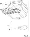
- Such machinery has some kind of shovel or scrapers, ( Fig. 9 ).
- the lip of such a shovel is provided with teeth.
- the shovel lip will have a series of mounting members. These may be themselves removable adaptors, or may be welded to the lip at spaced intervals. There may be twenty such mounting members on a shovel, for example, the number depending on the size, and the design of such a shovel. These mounting members usually carry removable adaptors. Teeth are then secured on the adaptors. In most case both the adaptors, and also the teeth are held on the shovel by some kind of lock or wedge. These typical locks or wedges are exposed at least in part to the outside environment around the teeth and adaptors.
- a typical shovel there may be for example twenty separate adaptors, carrying twenty separate teeth.
- the locking devices can be such that they will fit both the locking of the adaptors on the shovel mounting members, and also locking of the teeth on the adaptors.
- the present invention provides a locking device for such a purpose, i.e. locking either teeth on their adaptors, or locking the adaptors on tool mounts on the shovel.
- Each locking device is concealed within the adaptor or tooth or tool mount and is self-contained and carries its own internal power operated mechanism.
- the teeth and adaptors are formed with internal cavities or recesses. One of the cavities will receive the locking device within it, in the interior of the adaptor or mount.
- the other tool either the adaptor or the tooth itself, is provided with an interior socket, which will register with the interior cavity formed in the mount or adaptor.
- the locking device can be activated so as to lock the adaptor on the mount, or to lock the tooth on the adaptor.
- the locking devices themselves remain entirely concealed within the mount or adaptor, and are therefore protected from damage in use in the environment.
- the internal power operated mechanism incorporates known wireless technology, and can be activated by a wireless remote control.
- Fig 1 shows an adaptor (10), typically such as can be secured on a support member on a shovel ( Fig. 9 ).
- This adaptor (10) is of the type that can itself be removed from the shovel support member and replaced as needed.
- the adaptor (10) has a lock recess (12) to receive any suitable lock (not shown), by which the adaptor may be locked on the shovel support member.
- the adaptor (10) in this case is designed to support a tooth (14).
- the tooth (14) has a hollow interior (15) which fits over the leading portion (16) of the adaptor (10).
- the leading portion (16) of the adaptor has a body with a transverse cylindrical lock receiving recess (18), in one side.
- the adaptor body has a longitudinal axis, extending in the direction of the shovel movement.
- the cylindrical lock receiving recess is located on an axis normal to longitudinal axis. In this way the locking device will extend outwardly and inwardly in a transverse direction to the axis of the adaptor.
- the recess (18) has a rim (20) with two linear portions.
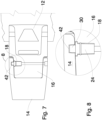
- the tooth (14) has a hollow body (15) with an interior hidden lock receiving socket (42) within the hollow body.
- a locking device (24) fits within the interior recess (18) of adaptor (10).
- the locking device (24) is shown in more detail in Figs 2 to 6 .
- the locking device (24) has a generally cylindrical body (26), defining a hollow interior (28).
- a sliding lock member (30) of partly cylindrical shape is slidable within the interior (28) of body (26).
- the lock member (30) is attached to a linear gear rack (32) formed with gear teeth.
- a drive gear (34) engages the gear teeth on the rack (32).
- Gear (34) is driven by an electric motor (36).
- Motor (36) is controlled and powered by circuits and battery (38), located within the interior of body (26).
- Sealing rings (40) are provided as needed on body (26).
- Tooth (14) has a hollow interior (15) ( Fig. 7 ) which fits over the leading end (16) of adaptor (10). Tooth (14) is formed with an interior lock receiving socket (42) in one side of the hollow interior of tooth (14), and is inaccessible from the exterior of the tooth (14). When the tooth (14) is fitted over the leading end (16) of the adaptor (10), the socket (42) is located so as to align with interior recess (18) of adaptor (10) and receive locking member (30).
- the socket (42) in the tooth is aligned transverse to the longitudinal axis of the tooth.
- the recess (18) and the socket (42) are both aligned with one another and are aligned transverse to the longitudinal axis of the tooth and the adaptor.
- Small diameter access drillings (44) are formed in adaptor (10) and in tooth (14), aligned with one another. Drillings (44) connect with the inner end of recess (18) to enable service persons to reach the locking device (24) from outside the tooth (14).
- the locking device (24) is entirely concealed within the body of the adaptor (10), and the tooth (14), and is not exposed on the exterior of either. In this way, the service life of the locking device (24) is greatly extended, and in practice it's operation by remote wireless technology, enables much quicker attention to servicing of the teeth on the shovel.
- the locking device In operation the locking device is first inserted in the cylindrical recess (18) of the adaptor (10), with its lock member (30) retracted.
- the tooth is then fitted over the leading end (16) of the adaptor (10).
- the tooth is slid on the adaptor (10) until the lock receiving recess (18) aligns with and registers with the lock receiving socket (42).
- the locking device is entirely concealed within and protected by the body of the adaptor (10), and is inaccessible manually from the exterior of the adaptor (10) or the tooth (14).
- W remote wireless device
- the motor (36) is then activated.
- the gear (34) rotates and moves the lock member (30) out of the body (26).
- the lock member will enter lock receiving socket (42) of the tooth (14) locking the tooth in position on the adaptor.
- the motor is then activated in reverse. This will retract the lock member (30) from the lock receiving socket (42) in the tooth back into the body (26).
- the tooth can then be removed from the adaptor.
- Locking of the adaptor on its shovel using such a locking device (24) will involve essentially the same operations.
- the power operated lock as described is capable of attaching removable attachments on earth moving machinery, whether such removable device is a tooth adaptor, or is a tooth itself, or of some other nature. Reference is therefore made in the claims to a releasable tool bit, it being the intention that this wording is generic to both the adaptor, and the tooth itself.
- each lock shall have its own unique signal.
- the operator of the equipment will have a hand-held device (W) capable of sending the separate individual signals, coded for the specific tool locks on the equipment.
- the method of the invention is self-explanatory from the above.
Landscapes
- Engineering & Computer Science (AREA)
- Mining & Mineral Resources (AREA)
- Civil Engineering (AREA)
- General Engineering & Computer Science (AREA)
- Structural Engineering (AREA)
- Mechanical Engineering (AREA)
- Operation Control Of Excavators (AREA)
- Lock And Its Accessories (AREA)
- Component Parts Of Construction Machinery (AREA)
- Details Of Connecting Devices For Male And Female Coupling (AREA)
- Manipulator (AREA)
- Operating, Guiding And Securing Of Roll- Type Closing Members (AREA)
Applications Claiming Priority (2)
| Application Number | Priority Date | Filing Date | Title |
|---|---|---|---|
| US201762469027P | 2017-03-09 | 2017-03-09 | |
| PCT/CA2018/050271 WO2018161166A1 (en) | 2017-03-09 | 2018-03-07 | Power operated locking system earth moving equipment and method |
Publications (3)
| Publication Number | Publication Date |
|---|---|
| EP3592905A1 EP3592905A1 (en) | 2020-01-15 |
| EP3592905A4 EP3592905A4 (en) | 2021-03-10 |
| EP3592905B1 true EP3592905B1 (en) | 2023-10-11 |
Family
ID=63446154
Family Applications (1)
| Application Number | Title | Priority Date | Filing Date |
|---|---|---|---|
| EP18763537.0A Active EP3592905B1 (en) | 2017-03-09 | 2018-03-07 | Power operated locking system earth moving equipment and method |
Country Status (12)
| Country | Link |
|---|---|
| US (3) | US10774500B2 (pl) |
| EP (1) | EP3592905B1 (pl) |
| CN (1) | CN110892116B (pl) |
| AU (1) | AU2018229712B2 (pl) |
| CA (1) | CA3055610A1 (pl) |
| CL (1) | CL2019002558A1 (pl) |
| ES (1) | ES2963908T3 (pl) |
| MX (1) | MX2019010579A (pl) |
| PL (1) | PL3592905T3 (pl) |
| RU (1) | RU2754897C2 (pl) |
| WO (1) | WO2018161166A1 (pl) |
| ZA (1) | ZA201906490B (pl) |
Families Citing this family (8)
| Publication number | Priority date | Publication date | Assignee | Title |
|---|---|---|---|---|
| US10774500B2 (en) * | 2017-03-09 | 2020-09-15 | Caterpillar Inc. | Power operated locking system earth moving equipment and method |
| EP3524737A1 (en) * | 2018-02-12 | 2019-08-14 | Metalogenia Research & Technologies S.L. | Fastening device for wear parts in earth-moving machines and system |
| AR119029A1 (es) * | 2019-05-31 | 2021-11-17 | Esco Group Llc | Monitoreo de productos de corte para equipos de movimiento de tierra |
| CN210405944U (zh) * | 2019-08-23 | 2020-04-24 | 京东方科技集团股份有限公司 | 防摔装置 |
| US11230827B2 (en) | 2019-11-08 | 2022-01-25 | Caterpillar Inc. | Electronically operated locking system for earth moving equipment and method |
| US11098463B2 (en) * | 2019-11-11 | 2021-08-24 | Caterpillar Inc. | Electrically activated polymer based locking system for earth moving equipment and method |
| WO2024011072A1 (en) | 2022-07-08 | 2024-01-11 | Caterpillar Inc. | Lock assembly for a tip and adapter |
| USD1040868S1 (en) | 2022-07-08 | 2024-09-03 | Caterpillar Inc. | Retention component |
Family Cites Families (56)
| Publication number | Priority date | Publication date | Assignee | Title |
|---|---|---|---|---|
| US2390286A (en) * | 1944-12-06 | 1945-12-04 | Adams Robert Clinton | Portable elevator |
| US2618873A (en) * | 1946-04-26 | 1952-11-25 | Morgan D Hostetter | Digger tooth construction |
| US2861362A (en) * | 1956-05-31 | 1958-11-25 | Liard Maurice | Digger tooth construction |
| US4413432A (en) * | 1982-07-09 | 1983-11-08 | Bierwith Robert S | Wedge and clamp locking system |
| SE452042B (sv) * | 1985-09-27 | 1987-11-09 | Per Danielsson | Forfarande och anordning for utbyte av en borrkrona pa plats i ett borrhal |
| US5049027A (en) * | 1990-02-21 | 1991-09-17 | Komatsu Dresser Company | Hydro-electric tool lock |
| US5063696A (en) * | 1991-02-13 | 1991-11-12 | Atlantic Richfield Company | Excavator bucket tooth retention device |
| US5159312A (en) * | 1991-04-01 | 1992-10-27 | Engle Edgar R | Double switch safety system and signaling device for a trailer hitch coupling |
| US5311681A (en) * | 1992-04-08 | 1994-05-17 | Gh Hensley Industries, Inc. | Retaining mechanism |
| US5435084A (en) * | 1994-02-17 | 1995-07-25 | Harnischfeger Corporation | Apparatus and method for attaching a digging tooth tip |
| AUPP342298A0 (en) * | 1998-05-08 | 1998-06-04 | Keech Castings Australia Pty Limited | Hydraulic fastening of components |
| US5709043A (en) * | 1995-12-11 | 1998-01-20 | Esco Corporation | Excavating tooth |
| US5937550A (en) * | 1995-12-11 | 1999-08-17 | Esco Corporation | Extensible lock |
| CA2312550C (en) * | 2000-06-27 | 2010-01-05 | Quality Steel Foundries Ltd. | Torque locking system for fastening a wear member to a support structure |
| US7219454B2 (en) * | 2000-08-04 | 2007-05-22 | Shark Abrasion Systems Pty. Ltd. | Attachment system |
| US6870485B2 (en) * | 2001-01-24 | 2005-03-22 | Kraig M. Lujan | Electronic method and apparatus for detecting and reporting dislocation of heavy mining equipment |
| AU2003275124B2 (en) * | 2002-09-19 | 2010-09-23 | Esco Corporation | Coupling arrangement |
| US6986216B2 (en) * | 2003-04-30 | 2006-01-17 | Esco Corporation | Wear assembly for the digging edge of an excavator |
| US7032333B2 (en) * | 2003-06-18 | 2006-04-25 | The Toro Company | Snowthrower chute and deflector control |
| US9359744B2 (en) * | 2009-08-05 | 2016-06-07 | H&L Tooth Company | Multipiece wear assembly |
| US9249558B2 (en) * | 2009-09-15 | 2016-02-02 | Robert S. Bierwith | Hydraulic locking mechanism for securing teeth and tooth carrying adapters to excavating buckets of excavating equipment |
| CA2788643C (en) * | 2010-02-02 | 2014-08-19 | Snap-On Incorporated | Tool box locking mechanisms for remote activation |
| US9562347B2 (en) * | 2010-08-04 | 2017-02-07 | H&L Tooth Company | Multipiece wear assembly |
| US8387290B2 (en) * | 2010-09-08 | 2013-03-05 | Hensley Industries, Inc. | Connector pin assembly with dual function outer end portions, and associated ground engaging apparatus |
| MX359765B (es) * | 2010-12-07 | 2018-10-10 | Talon Eng Sdn Bhd Company Number 1023659 H | Ensamble de conexión. |
| CL2011000274A1 (es) * | 2011-02-08 | 2011-05-20 | Sergio Monzon Osorio 90% | Sistema de alarma para detectar el desprendimiento de dientes y/o adaptadores en cucharones de palas de retroexcavacion. |
| CN103827407B (zh) * | 2011-05-20 | 2016-12-14 | 山特维克矿山工程机械澳大利亚(生产/供应)私人有限公司 | 地面接合耐磨部件和机械附连装置 |
| US20120304507A1 (en) * | 2011-06-01 | 2012-12-06 | Jung-Ching Ko | Structure of Bucket Tooth for Construction Tools |
| JO3726B1 (ar) * | 2011-07-14 | 2021-01-31 | Esco Group Llc | مجموعة بطانه |
| US8943717B2 (en) * | 2011-10-08 | 2015-02-03 | Caterpillar Inc. | Implement tooth assembly with tip and adapter |
| CA2852940C (en) * | 2011-10-20 | 2019-04-16 | Trinity Industries, Inc. | Tooth assembly for excavating apparatus with rare earth material |
| EP2783052B1 (en) * | 2011-11-23 | 2021-01-06 | ESCO Group LLC | Wear assembly |
| AU2012357712A1 (en) * | 2011-12-21 | 2014-07-24 | Simco Mining Products & Services Pty Ltd | Retainer systems |
| US20130269221A1 (en) * | 2012-04-11 | 2013-10-17 | Trinity Industries, Inc. | Assembly for an Excavating Apparatus with Flexible Reinforcement Collar |
| US8931190B2 (en) * | 2012-04-13 | 2015-01-13 | Raptor Mining Products Inc. | Excavator fastener |
| JP5891535B2 (ja) * | 2012-07-13 | 2016-03-23 | Smc株式会社 | 電動クランプ装置 |
| ITTO20130740A1 (it) * | 2013-09-12 | 2015-03-13 | Rialca Due Di Chiolerio Paolo Giova Nni | Dispositivo per il fissaggio di utensili a macchine operatrici mediante perni |
| US9200433B2 (en) * | 2013-10-03 | 2015-12-01 | Caterpillar Inc. | Tool retention system |
| WO2015142333A1 (en) * | 2014-03-20 | 2015-09-24 | Halliburton Energy Services, Inc. | Automated locking joint in a wellbore tool string |
| EP2952639A1 (en) * | 2014-06-02 | 2015-12-09 | Metalogenia Research & Technologies S.L. | Locking device for securing a wear member |
| US20160376771A1 (en) * | 2015-06-26 | 2016-12-29 | Caterpillar Inc. | Multi-sensor ultrasonic wear measurement system |
| US10106960B2 (en) * | 2015-11-25 | 2018-10-23 | Caterpillar Inc. | Lock assembly for ground engaging tool |
| CA2951741A1 (en) * | 2015-12-15 | 2017-06-15 | Pasquale Lombardo | Universal hammerless pin and retention assemblies |
| CA3226025A1 (en) * | 2016-02-08 | 2017-08-17 | Esco Group Llc | Wear assembly for earth working equipment |
| CN205636866U (zh) * | 2016-04-12 | 2016-10-12 | 天津市莎烽科技有限公司 | 新型挖掘机铲斗 |
| US10041231B2 (en) | 2016-04-28 | 2018-08-07 | Raptor Mining Products Inc. | Excavator tooth retention apparatus |
| US10407880B2 (en) * | 2016-06-24 | 2019-09-10 | Caterpillar Inc. | Wear member retention system for an implement |
| CN114277881B (zh) * | 2016-09-09 | 2023-11-17 | 久益环球地表采矿公司 | 地面接合工具锁定系统 |
| US10774500B2 (en) * | 2017-03-09 | 2020-09-15 | Caterpillar Inc. | Power operated locking system earth moving equipment and method |
| JP6345893B1 (ja) * | 2018-02-01 | 2018-06-20 | 生企工営株式会社 | 取付ピン組立体 |
| CA3103826A1 (en) * | 2018-06-29 | 2020-01-02 | Bradken Resources Pty Limited | Lock assembly for a wear assembly |
| TW202035831A (zh) * | 2019-02-08 | 2020-10-01 | 美商埃斯科集團有限公司 | 用於土方作業設備的磨損元件 |
| US11492784B2 (en) * | 2019-04-15 | 2022-11-08 | Hensley Industries, Inc. | Position-biased locking pin assembly for a ground engaging wear member |
| US11230827B2 (en) * | 2019-11-08 | 2022-01-25 | Caterpillar Inc. | Electronically operated locking system for earth moving equipment and method |
| US11098463B2 (en) * | 2019-11-11 | 2021-08-24 | Caterpillar Inc. | Electrically activated polymer based locking system for earth moving equipment and method |
| US11634892B2 (en) * | 2019-11-27 | 2023-04-25 | Hensley Industries, Inc. | Excavating tooth assembly with releasable lock pin assembly |
-
2018
- 2018-03-05 US US15/911,889 patent/US10774500B2/en active Active
- 2018-03-07 MX MX2019010579A patent/MX2019010579A/es unknown
- 2018-03-07 ES ES18763537T patent/ES2963908T3/es active Active
- 2018-03-07 WO PCT/CA2018/050271 patent/WO2018161166A1/en not_active Ceased
- 2018-03-07 CN CN201880016055.8A patent/CN110892116B/zh active Active
- 2018-03-07 AU AU2018229712A patent/AU2018229712B2/en active Active
- 2018-03-07 CA CA3055610A patent/CA3055610A1/en active Pending
- 2018-03-07 RU RU2019130106A patent/RU2754897C2/ru active
- 2018-03-07 EP EP18763537.0A patent/EP3592905B1/en active Active
- 2018-03-07 PL PL18763537.0T patent/PL3592905T3/pl unknown
-
2019
- 2019-09-06 CL CL2019002558A patent/CL2019002558A1/es unknown
- 2019-10-02 ZA ZA2019/06490A patent/ZA201906490B/en unknown
- 2019-11-01 US US16/671,456 patent/US11401682B2/en active Active
-
2022
- 2022-07-01 US US17/856,263 patent/US11959246B2/en active Active
Also Published As
| Publication number | Publication date |
|---|---|
| RU2019130106A (ru) | 2021-03-25 |
| US11401682B2 (en) | 2022-08-02 |
| EP3592905A4 (en) | 2021-03-10 |
| US20220333336A1 (en) | 2022-10-20 |
| US20180258607A1 (en) | 2018-09-13 |
| US20200141084A1 (en) | 2020-05-07 |
| AU2018229712A1 (en) | 2019-10-17 |
| US10774500B2 (en) | 2020-09-15 |
| RU2754897C2 (ru) | 2021-09-08 |
| EP3592905A1 (en) | 2020-01-15 |
| CL2019002558A1 (es) | 2020-02-07 |
| PL3592905T3 (pl) | 2024-01-29 |
| CA3055610A1 (en) | 2018-09-13 |
| CN110892116A (zh) | 2020-03-17 |
| MX2019010579A (es) | 2020-01-20 |
| WO2018161166A1 (en) | 2018-09-13 |
| US11959246B2 (en) | 2024-04-16 |
| ES2963908T3 (es) | 2024-04-03 |
| ZA201906490B (en) | 2020-12-23 |
| RU2019130106A3 (pl) | 2021-07-05 |
| BR112019018491A2 (pt) | 2020-05-05 |
| RU2021125930A (ru) | 2021-09-09 |
| AU2018229712B2 (en) | 2023-10-05 |
| CN110892116B (zh) | 2022-04-12 |
Similar Documents
| Publication | Publication Date | Title |
|---|---|---|
| EP3592905B1 (en) | Power operated locking system earth moving equipment and method | |
| JP7389878B2 (ja) | 土木機器に固設された地面係合摩耗部品のためのハンドリングシステム | |
| EP4055228B1 (en) | Electronically operated locking system for earth moving equipment and method | |
| US11686073B2 (en) | Electrically activated polymer based locking system for earth moving equipment and method | |
| RU2847620C2 (ru) | Стопорный механизм с электрическим приводом для землеройного оборудования и способ осуществления | |
| CA3156728C (en) | Electronically operated locking system for earth moving equipment and method | |
| CA3156735C (en) | Electrically activated polymer based power locking device for earth moving equipment | |
| BR112019018491B1 (pt) | Pá para equipamento de movimento de terra e método para prender remotamente uma ponta de ferramenta em uma montagem de ponta de ferramenta | |
| BR112022008619B1 (pt) | Adaptador e dispositivo de travamento de energia |
Legal Events
| Date | Code | Title | Description |
|---|---|---|---|
| STAA | Information on the status of an ep patent application or granted ep patent |
Free format text: STATUS: THE INTERNATIONAL PUBLICATION HAS BEEN MADE |
|
| PUAI | Public reference made under article 153(3) epc to a published international application that has entered the european phase |
Free format text: ORIGINAL CODE: 0009012 |
|
| STAA | Information on the status of an ep patent application or granted ep patent |
Free format text: STATUS: REQUEST FOR EXAMINATION WAS MADE |
|
| 17P | Request for examination filed |
Effective date: 20191008 |
|
| AK | Designated contracting states |
Kind code of ref document: A1 Designated state(s): AL AT BE BG CH CY CZ DE DK EE ES FI FR GB GR HR HU IE IS IT LI LT LU LV MC MK MT NL NO PL PT RO RS SE SI SK SM TR |
|
| AX | Request for extension of the european patent |
Extension state: BA ME |
|
| DAV | Request for validation of the european patent (deleted) | ||
| DAX | Request for extension of the european patent (deleted) | ||
| A4 | Supplementary search report drawn up and despatched |
Effective date: 20210208 |
|
| RIC1 | Information provided on ipc code assigned before grant |
Ipc: E02F 3/36 20060101ALI20210202BHEP Ipc: E02F 9/28 20060101AFI20210202BHEP Ipc: E02F 9/00 20060101ALI20210202BHEP Ipc: E05B 47/00 20060101ALI20210202BHEP |
|
| GRAP | Despatch of communication of intention to grant a patent |
Free format text: ORIGINAL CODE: EPIDOSNIGR1 |
|
| STAA | Information on the status of an ep patent application or granted ep patent |
Free format text: STATUS: GRANT OF PATENT IS INTENDED |
|
| INTG | Intention to grant announced |
Effective date: 20230511 |
|
| GRAS | Grant fee paid |
Free format text: ORIGINAL CODE: EPIDOSNIGR3 |
|
| GRAA | (expected) grant |
Free format text: ORIGINAL CODE: 0009210 |
|
| STAA | Information on the status of an ep patent application or granted ep patent |
Free format text: STATUS: THE PATENT HAS BEEN GRANTED |
|
| P01 | Opt-out of the competence of the unified patent court (upc) registered |
Effective date: 20230825 |
|
| AK | Designated contracting states |
Kind code of ref document: B1 Designated state(s): AL AT BE BG CH CY CZ DE DK EE ES FI FR GB GR HR HU IE IS IT LI LT LU LV MC MK MT NL NO PL PT RO RS SE SI SK SM TR |
|
| RAP3 | Party data changed (applicant data changed or rights of an application transferred) |
Owner name: CATERPILLAR INC. |
|
| REG | Reference to a national code |
Ref country code: GB Ref legal event code: FG4D |
|
| REG | Reference to a national code |
Ref country code: CH Ref legal event code: EP |
|
| REG | Reference to a national code |
Ref country code: DE Ref legal event code: R096 Ref document number: 602018059198 Country of ref document: DE |
|
| REG | Reference to a national code |
Ref country code: IE Ref legal event code: FG4D |
|
| REG | Reference to a national code |
Ref country code: SE Ref legal event code: TRGR |
|
| REG | Reference to a national code |
Ref country code: NO Ref legal event code: T2 Effective date: 20231011 |
|
| REG | Reference to a national code |
Ref country code: LT Ref legal event code: MG9D |
|
| REG | Reference to a national code |
Ref country code: NL Ref legal event code: MP Effective date: 20231011 |
|
| PG25 | Lapsed in a contracting state [announced via postgrant information from national office to epo] |
Ref country code: NL Free format text: LAPSE BECAUSE OF FAILURE TO SUBMIT A TRANSLATION OF THE DESCRIPTION OR TO PAY THE FEE WITHIN THE PRESCRIBED TIME-LIMIT Effective date: 20231011 |
|
| REG | Reference to a national code |
Ref country code: ES Ref legal event code: FG2A Ref document number: 2963908 Country of ref document: ES Kind code of ref document: T3 Effective date: 20240403 |
|
| PG25 | Lapsed in a contracting state [announced via postgrant information from national office to epo] |
Ref country code: GR Free format text: LAPSE BECAUSE OF FAILURE TO SUBMIT A TRANSLATION OF THE DESCRIPTION OR TO PAY THE FEE WITHIN THE PRESCRIBED TIME-LIMIT Effective date: 20240112 |
|
| PG25 | Lapsed in a contracting state [announced via postgrant information from national office to epo] |
Ref country code: IS Free format text: LAPSE BECAUSE OF FAILURE TO SUBMIT A TRANSLATION OF THE DESCRIPTION OR TO PAY THE FEE WITHIN THE PRESCRIBED TIME-LIMIT Effective date: 20240211 |
|
| PG25 | Lapsed in a contracting state [announced via postgrant information from national office to epo] |
Ref country code: LT Free format text: LAPSE BECAUSE OF FAILURE TO SUBMIT A TRANSLATION OF THE DESCRIPTION OR TO PAY THE FEE WITHIN THE PRESCRIBED TIME-LIMIT Effective date: 20231011 |
|
| PG25 | Lapsed in a contracting state [announced via postgrant information from national office to epo] |
Ref country code: LT Free format text: LAPSE BECAUSE OF FAILURE TO SUBMIT A TRANSLATION OF THE DESCRIPTION OR TO PAY THE FEE WITHIN THE PRESCRIBED TIME-LIMIT Effective date: 20231011 Ref country code: IS Free format text: LAPSE BECAUSE OF FAILURE TO SUBMIT A TRANSLATION OF THE DESCRIPTION OR TO PAY THE FEE WITHIN THE PRESCRIBED TIME-LIMIT Effective date: 20240211 Ref country code: GR Free format text: LAPSE BECAUSE OF FAILURE TO SUBMIT A TRANSLATION OF THE DESCRIPTION OR TO PAY THE FEE WITHIN THE PRESCRIBED TIME-LIMIT Effective date: 20240112 Ref country code: BG Free format text: LAPSE BECAUSE OF FAILURE TO SUBMIT A TRANSLATION OF THE DESCRIPTION OR TO PAY THE FEE WITHIN THE PRESCRIBED TIME-LIMIT Effective date: 20240111 Ref country code: PT Free format text: LAPSE BECAUSE OF FAILURE TO SUBMIT A TRANSLATION OF THE DESCRIPTION OR TO PAY THE FEE WITHIN THE PRESCRIBED TIME-LIMIT Effective date: 20240212 |
|
| PG25 | Lapsed in a contracting state [announced via postgrant information from national office to epo] |
Ref country code: RS Free format text: LAPSE BECAUSE OF FAILURE TO SUBMIT A TRANSLATION OF THE DESCRIPTION OR TO PAY THE FEE WITHIN THE PRESCRIBED TIME-LIMIT Effective date: 20231011 Ref country code: LV Free format text: LAPSE BECAUSE OF FAILURE TO SUBMIT A TRANSLATION OF THE DESCRIPTION OR TO PAY THE FEE WITHIN THE PRESCRIBED TIME-LIMIT Effective date: 20231011 Ref country code: HR Free format text: LAPSE BECAUSE OF FAILURE TO SUBMIT A TRANSLATION OF THE DESCRIPTION OR TO PAY THE FEE WITHIN THE PRESCRIBED TIME-LIMIT Effective date: 20231011 |
|
| PG25 | Lapsed in a contracting state [announced via postgrant information from national office to epo] |
Ref country code: DK Free format text: LAPSE BECAUSE OF FAILURE TO SUBMIT A TRANSLATION OF THE DESCRIPTION OR TO PAY THE FEE WITHIN THE PRESCRIBED TIME-LIMIT Effective date: 20231011 |
|
| REG | Reference to a national code |
Ref country code: DE Ref legal event code: R097 Ref document number: 602018059198 Country of ref document: DE |
|
| PG25 | Lapsed in a contracting state [announced via postgrant information from national office to epo] |
Ref country code: CZ Free format text: LAPSE BECAUSE OF FAILURE TO SUBMIT A TRANSLATION OF THE DESCRIPTION OR TO PAY THE FEE WITHIN THE PRESCRIBED TIME-LIMIT Effective date: 20231011 |
|
| PG25 | Lapsed in a contracting state [announced via postgrant information from national office to epo] |
Ref country code: SK Free format text: LAPSE BECAUSE OF FAILURE TO SUBMIT A TRANSLATION OF THE DESCRIPTION OR TO PAY THE FEE WITHIN THE PRESCRIBED TIME-LIMIT Effective date: 20231011 |
|
| PG25 | Lapsed in a contracting state [announced via postgrant information from national office to epo] |
Ref country code: SM Free format text: LAPSE BECAUSE OF FAILURE TO SUBMIT A TRANSLATION OF THE DESCRIPTION OR TO PAY THE FEE WITHIN THE PRESCRIBED TIME-LIMIT Effective date: 20231011 Ref country code: SK Free format text: LAPSE BECAUSE OF FAILURE TO SUBMIT A TRANSLATION OF THE DESCRIPTION OR TO PAY THE FEE WITHIN THE PRESCRIBED TIME-LIMIT Effective date: 20231011 Ref country code: RO Free format text: LAPSE BECAUSE OF FAILURE TO SUBMIT A TRANSLATION OF THE DESCRIPTION OR TO PAY THE FEE WITHIN THE PRESCRIBED TIME-LIMIT Effective date: 20231011 Ref country code: EE Free format text: LAPSE BECAUSE OF FAILURE TO SUBMIT A TRANSLATION OF THE DESCRIPTION OR TO PAY THE FEE WITHIN THE PRESCRIBED TIME-LIMIT Effective date: 20231011 Ref country code: DK Free format text: LAPSE BECAUSE OF FAILURE TO SUBMIT A TRANSLATION OF THE DESCRIPTION OR TO PAY THE FEE WITHIN THE PRESCRIBED TIME-LIMIT Effective date: 20231011 Ref country code: CZ Free format text: LAPSE BECAUSE OF FAILURE TO SUBMIT A TRANSLATION OF THE DESCRIPTION OR TO PAY THE FEE WITHIN THE PRESCRIBED TIME-LIMIT Effective date: 20231011 |
|
| PLBE | No opposition filed within time limit |
Free format text: ORIGINAL CODE: 0009261 |
|
| STAA | Information on the status of an ep patent application or granted ep patent |
Free format text: STATUS: NO OPPOSITION FILED WITHIN TIME LIMIT |
|
| 26N | No opposition filed |
Effective date: 20240712 |
|
| PG25 | Lapsed in a contracting state [announced via postgrant information from national office to epo] |
Ref country code: SI Free format text: LAPSE BECAUSE OF FAILURE TO SUBMIT A TRANSLATION OF THE DESCRIPTION OR TO PAY THE FEE WITHIN THE PRESCRIBED TIME-LIMIT Effective date: 20231011 |
|
| PG25 | Lapsed in a contracting state [announced via postgrant information from national office to epo] |
Ref country code: SI Free format text: LAPSE BECAUSE OF FAILURE TO SUBMIT A TRANSLATION OF THE DESCRIPTION OR TO PAY THE FEE WITHIN THE PRESCRIBED TIME-LIMIT Effective date: 20231011 |
|
| PG25 | Lapsed in a contracting state [announced via postgrant information from national office to epo] |
Ref country code: LU Free format text: LAPSE BECAUSE OF NON-PAYMENT OF DUE FEES Effective date: 20240307 |
|
| PG25 | Lapsed in a contracting state [announced via postgrant information from national office to epo] |
Ref country code: MC Free format text: LAPSE BECAUSE OF FAILURE TO SUBMIT A TRANSLATION OF THE DESCRIPTION OR TO PAY THE FEE WITHIN THE PRESCRIBED TIME-LIMIT Effective date: 20231011 |
|
| PG25 | Lapsed in a contracting state [announced via postgrant information from national office to epo] |
Ref country code: LU Free format text: LAPSE BECAUSE OF NON-PAYMENT OF DUE FEES Effective date: 20240307 Ref country code: MC Free format text: LAPSE BECAUSE OF FAILURE TO SUBMIT A TRANSLATION OF THE DESCRIPTION OR TO PAY THE FEE WITHIN THE PRESCRIBED TIME-LIMIT Effective date: 20231011 |
|
| REG | Reference to a national code |
Ref country code: BE Ref legal event code: MM Effective date: 20240331 |
|
| PG25 | Lapsed in a contracting state [announced via postgrant information from national office to epo] |
Ref country code: BE Free format text: LAPSE BECAUSE OF NON-PAYMENT OF DUE FEES Effective date: 20240331 |
|
| PG25 | Lapsed in a contracting state [announced via postgrant information from national office to epo] |
Ref country code: IE Free format text: LAPSE BECAUSE OF NON-PAYMENT OF DUE FEES Effective date: 20240307 |
|
| PG25 | Lapsed in a contracting state [announced via postgrant information from national office to epo] |
Ref country code: IE Free format text: LAPSE BECAUSE OF NON-PAYMENT OF DUE FEES Effective date: 20240307 Ref country code: BE Free format text: LAPSE BECAUSE OF NON-PAYMENT OF DUE FEES Effective date: 20240331 |
|
| PGFP | Annual fee paid to national office [announced via postgrant information from national office to epo] |
Ref country code: ES Payment date: 20250401 Year of fee payment: 8 |
|
| PGFP | Annual fee paid to national office [announced via postgrant information from national office to epo] |
Ref country code: CH Payment date: 20250401 Year of fee payment: 8 |
|
| PG25 | Lapsed in a contracting state [announced via postgrant information from national office to epo] |
Ref country code: CY Free format text: LAPSE BECAUSE OF FAILURE TO SUBMIT A TRANSLATION OF THE DESCRIPTION OR TO PAY THE FEE WITHIN THE PRESCRIBED TIME-LIMIT; INVALID AB INITIO Effective date: 20180307 |
|
| PG25 | Lapsed in a contracting state [announced via postgrant information from national office to epo] |
Ref country code: HU Free format text: LAPSE BECAUSE OF FAILURE TO SUBMIT A TRANSLATION OF THE DESCRIPTION OR TO PAY THE FEE WITHIN THE PRESCRIBED TIME-LIMIT; INVALID AB INITIO Effective date: 20180307 |
|
| PG25 | Lapsed in a contracting state [announced via postgrant information from national office to epo] |
Ref country code: FI Free format text: LAPSE BECAUSE OF FAILURE TO SUBMIT A TRANSLATION OF THE DESCRIPTION OR TO PAY THE FEE WITHIN THE PRESCRIBED TIME-LIMIT Effective date: 20231011 |
|
| REG | Reference to a national code |
Ref country code: AT Ref legal event code: UEP Ref document number: 1620350 Country of ref document: AT Kind code of ref document: T Effective date: 20231011 |
|
| REG | Reference to a national code |
Ref country code: CH Ref legal event code: U11 Free format text: ST27 STATUS EVENT CODE: U-0-0-U10-U11 (AS PROVIDED BY THE NATIONAL OFFICE) Effective date: 20260401 |
|
| PGFP | Annual fee paid to national office [announced via postgrant information from national office to epo] |
Ref country code: SE Payment date: 20260219 Year of fee payment: 9 |
|
| PGFP | Annual fee paid to national office [announced via postgrant information from national office to epo] |
Ref country code: GB Payment date: 20260219 Year of fee payment: 9 |
|
| PGFP | Annual fee paid to national office [announced via postgrant information from national office to epo] |
Ref country code: NO Payment date: 20260223 Year of fee payment: 9 Ref country code: DE Payment date: 20260219 Year of fee payment: 9 |
|
| PGFP | Annual fee paid to national office [announced via postgrant information from national office to epo] |
Ref country code: AT Payment date: 20260223 Year of fee payment: 9 |
|
| PGFP | Annual fee paid to national office [announced via postgrant information from national office to epo] |
Ref country code: IT Payment date: 20260219 Year of fee payment: 9 |
|
| PGFP | Annual fee paid to national office [announced via postgrant information from national office to epo] |
Ref country code: FR Payment date: 20260219 Year of fee payment: 9 |
|
| PGFP | Annual fee paid to national office [announced via postgrant information from national office to epo] |
Ref country code: TR Payment date: 20260223 Year of fee payment: 9 |
|
| PGFP | Annual fee paid to national office [announced via postgrant information from national office to epo] |
Ref country code: PL Payment date: 20260224 Year of fee payment: 9 |