EP3592160B1 - Feeding device and method for feeding spherical objects in a tobacco industry machine - Google Patents
Feeding device and method for feeding spherical objects in a tobacco industry machine Download PDFInfo
- Publication number
- EP3592160B1 EP3592160B1 EP18710430.2A EP18710430A EP3592160B1 EP 3592160 B1 EP3592160 B1 EP 3592160B1 EP 18710430 A EP18710430 A EP 18710430A EP 3592160 B1 EP3592160 B1 EP 3592160B1
- Authority
- EP
- European Patent Office
- Prior art keywords
- chamber
- single layer
- mass
- spherical objects
- rotary element
- Prior art date
- Legal status (The legal status is an assumption and is not a legal conclusion. Google has not performed a legal analysis and makes no representation as to the accuracy of the status listed.)
- Active
Links
Images



Classifications
-
- A—HUMAN NECESSITIES
- A24—TOBACCO; CIGARS; CIGARETTES; SIMULATED SMOKING DEVICES; SMOKERS' REQUISITES
- A24D—CIGARS; CIGARETTES; TOBACCO SMOKE FILTERS; MOUTHPIECES OF CIGARS OR CIGARETTES; MANUFACTURE OF TOBACCO SMOKE FILTERS OR MOUTHPIECES
- A24D3/00—Tobacco smoke filters, e.g. filter tips or filtering inserts; Filters specially adapted for simulated smoking devices; Mouthpieces of cigars or cigarettes
- A24D3/02—Manufacture of tobacco smoke filters
- A24D3/0204—Preliminary operations before the filter rod forming process, e.g. crimping, blooming
- A24D3/0212—Applying additives to filter materials
- A24D3/0216—Applying additives to filter materials the additive being in the form of capsules, beads or the like
Definitions
- the present disclosure relates to a feeding device for feeding spherical objects, applicable for tobacco industry, and to a method for feeding spherical objects in a tobacco industry machine.
- Tobacco industry products may comprise capsules with scent substances.
- the capsules can be placed in cigarette filters, and the smokers, before or during smoking, can squeeze the capsule with their fingers to release the scent.
- the capsules may be placed in a filtering material.
- cigarettes with two capsules placed in a mouthpiece in the filtering material wherein the two capsules may be squeezed separately or both at the same time.
- mouthpieces for cigarettes which are made of two or more different filtering segments, where the capsules may be placed in a space between the segments.
- the capsules are delivered to a feeding machine, for feeding the capsules in the filtering material, usually in a mass flow, i.e. are poured into a mass container.
- the capsules are transferred from the mass container to the device, which places them one by one into the filtering material.
- the capsules received from the mass container have to be transferred to the device which handles single capsules or a stream of single capsules.
- a US patent application US2007068540A1 discloses a device, in which capsules are received from a mass chamber and are transferred to a single layer chamber. From the single layer of capsules, the capsules are received by means of sockets of a feeding wheel and as a result the stream of single capsules moving on a circular path, is formed. From the feeding wheel the capsules are transferred to the filtering material band.
- a PCT patent application WO2005032286A2 discloses a device in which capsules are received from a rotary container by means of negative pressure and are transferred to sockets of a feeding wheel.
- a PCT patent application WO2011083405A1 discloses a device in which separate streams are formed of capsules from a rotary mass chamber, wherein the streams move in horizontal ducts, wherein the ducts rotate together with the mass chamber.
- a US patent US7757835B2 discloses a device wherein streams of capsules move at a certain angle.
- JPH06135542A discloses a bead feeding apparatus comprising a mass hopper and a single layer hopper, the beads flowing from the mass hopper to the single layer hopper. Above the entrance to the single layer hopper there is provided a rotary cylinder the task of which is forming a single layer flow of beads. Further from the single layer hopper the beads are delivered through pipe channels to feeding units provided with rotary feeders.
- the capsules are also referred to as spherical objects.
- a mass chamber 2 for capsules 3, in a feeding device 1 presented in Fig. 1 has a form of a container that is open at the top and at the bottom and comprises sidewalls 4, 5, a front wall 6 and an inclined bottom 7.
- the front wall 6 and the bottom 7 are convergent, forming an outlet 8 in a lower part 2A of the mass chamber 2.
- the mass chamber 2 may have other shapes as well.
- the capsules 3 may be delivered to the mass chamber 2 manually, by means of a container or by means of a typical feeding unit, for example a pneumatic feeding unit or a mechanical feeding unit with a transporter for capsules 3, wherein the feeding unit is not shown in the drawing.
- a typical feeding unit for example a pneumatic feeding unit or a mechanical feeding unit with a transporter for capsules 3, wherein the feeding unit is not shown in the drawing.
- a cylindrical rotary element 9 is located under the bottom 7 along a bottom edge 7A of the bottom 7, wherein a driving unit for rotating this element is not shown for clarity.
- the cylindrical rotary element rotates in a direction depicted by an arrow 9R, it means that it rotates such that its surface of contact with the capsules 3, moves in an opposite direction to the direction of flow of the capsules from the mass chamber 2 to a single layer chamber 10.
- the device may also operate when the cylindrical rotary element 9 rotates in an opposite direction, i.e. when it rotates such that its surface of contact with the capsules 3 moves in the same direction as the direction of flow of the capsules from the mass chamber 2 to the single layer chamber 10.
- the capsules 3 rotate due to the action of the force of friction between a surface of the capsules 3 and a rotating side surface 9A.
- the rotation of the capsules 3 facilitates their downward movement, because it reduces at least partially situations wherein non-rotating capsules could be blocked between the outlet 8 of the mass chamber and a front wall 11 of the single layer chamber 10.
- An axis of rotation X of the cylindrical rotary element 9 is substantially in parallel to the bottom edge 7A. Between the bottom edge 7A and the side surface 9A of the cylindrical rotary element 9 there is a gap, which has a width smaller than a diameter of the capsule 3.
- the cylindrical rotary element 9 may be located such that its side surface 9A is tangential to an inner surface 7B of the bottom 7 and it constitutes an extension of the bottom 7.
- the length of the cylindrical rotary element 9 is at least equal to the length of the edge 7A of the bottom 7.
- the length of the cylindrical rotary element 9 is substantially equal to a length of the outlet 8.
- the single layer chamber 10 is attached to the mass chamber 2.
- the front wall 11 of the single layer chamber 10 forms an extension of the front wall 6 of the mass chamber 2, wherein the length of the single layer chamber 10 is equal to the length of the outlet 8 of the mass chamber 2.
- Another wall 12 of the single layer chamber 10 is spaced apart from its front wall 11 by a distance slightly greater than the diameter of the capsule 3, such as to enable the capsules 3 to fall under the force of gravity in the single layer chamber 10.
- an inner surface 12A of the wall 12 is preferably located tangentially to the side surface 9A of the cylindrical rotary element 9.
- the single layer chamber 10 is located vertically, but it may also be inclined in order to slow down sliding of the capsules and to increase the smoothness of the flow of the capsules.
- Side walls 13 and 14 of the single layer chamber 10 are arranged substantially in parallel to each other, and they may be also arranged convergently or divergently in a downward direction.
- an outlet 15 having a form of multiple outlet ducts 16.
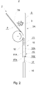
- At an inlet 16E of the outlet duct 16 there are two rollers 17, 18, wherein their circumferential surfaces 17A, 18A constitute walls of the outlet duct 16.
- the inlet 16E of the outlet duct 16 is formed by the surfaces 17A, 18A and the surfaces 11A and 12A of the walls 11 and 12 ( Fig. 2 ).
- the rollers 17, 18 are mounted pivotally, wherein for clarity of the drawing, a driving unit of the rollers is not shown. As presented in Fig. 1 and Fig.
- the rollers 17, 18 rotate in the same directions 17R and 18R, so their circumferential surfaces 17A, 18A move in opposite directions with respect to the inlet 16E of the outlet duct 16. Therefore, when the capsules 3 are above the rollers 17, 18, some of them will be displaced or will be pushed by one of the rollers (the circumferential surface of which moves in a direction towards the inlet of the outlet duct) towards the inlet, and the rest of the capsules will be displaced or pushed by the second roller (the circumferential surface of which moves in a direction opposite to the inlet of the outlet duct) in the direction opposite to the outlet - it allows to prevent blocking of the capsules 3 and provides good flow conditions of the capsules 3 from the single layer chamber 10 to the outlet ducts 16.
- rollers of the consecutive pairs of rollers 18 and 17', 17' and 18', 18' and 17", 17" and 18" rotate in a similar manner.
- the ducts and rollers are arranged such that one roller 18, 17', 18', 17" cooperates with two outlet ducts 16, i.e. the circumferential surface of one roller constitutes the wall of one duct and of the neighboring duct.
- distributors 19 shown in Fig. 4 ) for directing the capsules 3 to particular outlet ducts 16.
- Fig. 5 shows another embodiment of a feeding device 1' - having a doubled efficiency with respect to the feeding device 1 shown in Fig. 1 .
- the feeding device 1' has a mass chamber 2' having side walls 4, 5, a front wall 6 and a back wall 6' and a bottom 7', which comprises two surfaces 7B and 7B'.
- the mass chamber 2' is connected with two single layer chambers 10 and 10'.
- a first cylindrical rotary element 9 is located in the region of the connection of the mass chamber 2' with the single layer chamber 10, and a second cylindrical rotary element 9' is located in the region of the connection of the mass chamber 2' with the single layer chamber 10'.
- the feeding device 1' in a top view, occupies a similar area as the feeding device 1 of Fig. 1 , but it allows to deliver twice as much of the capsules.
- one cylindrical rotary element 9 which is located in the region of connection of the mass chamber 2' with the single layer chamber 10, tangentially to the surface 7B and in the region of the connection of the mass chamber 2' with the single layer chamber 10', tangentially to the surface 7B'.
- Initializing the rotation of the cylindrical rotary element 9, 9', wherein its side surface 9A constitutes a fragment of the bottom of the mass chamber causes the capsules to begin to rotate with respect to the cylindrical rotary element 9, 9' and with respect to other capsules 3.
- Such location of the cylindrical rotary element is preferable, because the capsules do not have a possibility to block each other at the inlet to the single layer chamber 10, 10' during the operation of the device.
- the device as presented herein may be further extended to achieve a desired amount of outlet ducts, depending on the efficiency of the receiving device.
- one mass chamber may be connected with several single layer chambers.
- the single layer chamber together with the duct (or ducts) and the rotary element (or rotary elements) may form a module which may be connected to improve a previously constructed device.
- some of the outlets may be blocked, so as to adapt the efficiency of the feeding device to the receiving efficiency of cooperating devices.
Landscapes
- Filling Or Emptying Of Bunkers, Hoppers, And Tanks (AREA)
- Manufacturing Of Cigar And Cigarette Tobacco (AREA)
- Cigarettes, Filters, And Manufacturing Of Filters (AREA)
Applications Claiming Priority (2)
| Application Number | Priority Date | Filing Date | Title |
|---|---|---|---|
| PL420798A PL239186B1 (pl) | 2017-03-10 | 2017-03-10 | Urządzenie zasilające do podawania obiektów sferycznych dla przemysłu tytoniowego i sposób podawania obiektów sferycznych w maszynie przemysłu tytoniowego |
| PCT/EP2018/055691 WO2018162608A1 (en) | 2017-03-10 | 2018-03-08 | Feeding device and method for feeding spherical objects in a tobacco industry machine |
Publications (2)
| Publication Number | Publication Date |
|---|---|
| EP3592160A1 EP3592160A1 (en) | 2020-01-15 |
| EP3592160B1 true EP3592160B1 (en) | 2023-01-11 |
Family
ID=61622579
Family Applications (1)
| Application Number | Title | Priority Date | Filing Date |
|---|---|---|---|
| EP18710430.2A Active EP3592160B1 (en) | 2017-03-10 | 2018-03-08 | Feeding device and method for feeding spherical objects in a tobacco industry machine |
Country Status (9)
| Country | Link |
|---|---|
| US (1) | US20200120975A1 (https=) |
| EP (1) | EP3592160B1 (https=) |
| JP (1) | JP2020513797A (https=) |
| KR (1) | KR20190126001A (https=) |
| CN (1) | CN110475485A (https=) |
| BR (1) | BR112019018711A2 (https=) |
| PL (1) | PL239186B1 (https=) |
| RU (1) | RU2759456C2 (https=) |
| WO (1) | WO2018162608A1 (https=) |
Families Citing this family (3)
| Publication number | Priority date | Publication date | Assignee | Title |
|---|---|---|---|---|
| EP3842365A1 (en) | 2019-12-23 | 2021-06-30 | International Tobacco Machinery Poland SP. Z O.O. | A method for transferring objects in channels and a channel system for transferring objects for tobacco industry |
| CN113510455B (zh) * | 2021-04-30 | 2022-06-24 | 西安秦泰汽车排放技术有限公司 | 一种用于自动排出球类零件的装置 |
| IT202100013220A1 (it) * | 2021-05-20 | 2022-11-20 | Ima Spa | Apparecchiatura e procedimento di riempimento per riempire automaticamente contenitori |
Family Cites Families (15)
| Publication number | Priority date | Publication date | Assignee | Title |
|---|---|---|---|---|
| US4063633A (en) * | 1976-11-10 | 1977-12-20 | Liggett Group Inc. | Vacuum plug feed machine |
| JPH03162314A (ja) * | 1989-11-22 | 1991-07-12 | Sakura Color Prod Corp | ブリッジブレーカ |
| JPH0522424U (ja) * | 1991-05-30 | 1993-03-23 | 三菱マテリアル株式会社 | 缶の整列供給装置 |
| JPH0670739A (ja) * | 1992-08-24 | 1994-03-15 | Japan Tobacco Inc | フィルタロッド製造機 |
| JPH06135542A (ja) * | 1992-10-22 | 1994-05-17 | Japan Tobacco Inc | 球状物の供給装置 |
| US7115085B2 (en) | 2003-09-12 | 2006-10-03 | R.J. Reynolds Tobacco Company | Method and apparatus for incorporating objects into cigarette filters |
| US7479098B2 (en) | 2005-09-23 | 2009-01-20 | R. J. Reynolds Tobacco Company | Equipment for insertion of objects into smoking articles |
| US7757835B2 (en) | 2007-12-05 | 2010-07-20 | Philip Moris Usa Inc. | Bead feeder |
| ZA200905994B (en) * | 2009-08-28 | 2014-05-28 | Tobacco Res And Dev Inst (Pty) Ltd | Filter rod maker |
| US20110162662A1 (en) | 2010-01-05 | 2011-07-07 | Aiger Group Ag | Apparatus and method for insertion of capsules into filter tows |
| IT1408375B1 (it) * | 2010-10-20 | 2014-06-20 | Gd Spa | Unita' e metodo di alimentazione di elementi additivi a del materiale fibroso in una macchina per la produzione di articoli da fumo |
| WO2012076496A1 (en) * | 2010-12-07 | 2012-06-14 | Philip Morris Products S.A. | Method and apparatus for introducing objects into a continuous flow of material |
| BR112013032904B1 (pt) * | 2011-06-20 | 2021-01-05 | Philip Morris Products S.A. | aparelho e método para introduzir objetos dentro de um fluxo contínuo de material |
| PL227873B1 (pl) | 2012-01-18 | 2018-01-31 | International Tobacco Machinery Poland Spólka Z Ograniczona Odpowiedzialnoscia | Sposób podawania kapsułek i zespół do podawania kapsułek |
| CN204169048U (zh) * | 2014-09-28 | 2015-02-25 | 台州市天鸿烟草机械制造有限公司 | 滤棒成型机加胶囊装置 |
-
2017
- 2017-03-10 PL PL420798A patent/PL239186B1/pl unknown
-
2018
- 2018-03-08 KR KR1020197029671A patent/KR20190126001A/ko not_active Ceased
- 2018-03-08 EP EP18710430.2A patent/EP3592160B1/en active Active
- 2018-03-08 BR BR112019018711A patent/BR112019018711A2/pt not_active Application Discontinuation
- 2018-03-08 RU RU2019129906A patent/RU2759456C2/ru active
- 2018-03-08 US US16/493,302 patent/US20200120975A1/en not_active Abandoned
- 2018-03-08 CN CN201880017356.2A patent/CN110475485A/zh active Pending
- 2018-03-08 WO PCT/EP2018/055691 patent/WO2018162608A1/en not_active Ceased
- 2018-03-08 JP JP2019547679A patent/JP2020513797A/ja active Pending
Also Published As
| Publication number | Publication date |
|---|---|
| KR20190126001A (ko) | 2019-11-07 |
| CN110475485A (zh) | 2019-11-19 |
| JP2020513797A (ja) | 2020-05-21 |
| US20200120975A1 (en) | 2020-04-23 |
| BR112019018711A2 (pt) | 2020-04-07 |
| RU2019129906A3 (https=) | 2021-03-25 |
| PL420798A1 (pl) | 2018-09-24 |
| RU2759456C2 (ru) | 2021-11-15 |
| WO2018162608A1 (en) | 2018-09-13 |
| RU2019129906A (ru) | 2021-03-24 |
| EP3592160A1 (en) | 2020-01-15 |
| PL239186B1 (pl) | 2021-11-15 |
Similar Documents
| Publication | Publication Date | Title |
|---|---|---|
| JP6259571B2 (ja) | ビーズを供給する方法及び装置 | |
| JP6259572B2 (ja) | ビーズ供給方法及びビーズ供給装置 | |
| EP2617665B1 (en) | Bead feeding method and bead feeder | |
| JP5438237B2 (ja) | ビーズの不均等な移送方法及びユニット | |
| EP3592160B1 (en) | Feeding device and method for feeding spherical objects in a tobacco industry machine | |
| CN106535671B (zh) | 供给单元 | |
| US11219241B2 (en) | Bead feeding method and bead feeding unit | |
| EP3089600B1 (en) | Apparatus and method for introducing objects into a flow of filter material | |
| EP3661376B1 (en) | Method and apparatus for producing micro bead bearing filter rod | |
| CN109640709B (zh) | 清洁单元、烟草工业机器和清洁棒状元件的列的方法 | |
| JP3413287B2 (ja) | 棒状物空気搬送装置 | |
| KR20220014822A (ko) | 비드들을 공급하기 위한 공급 유닛 및 로드들을 제조하기 위한 장치 | |
| JP5594794B2 (ja) | 粒状物の供給装置及びその供給方法 | |
| CN109964991A (zh) | 分离涂覆处理中的肉制品流的装置和方法 |
Legal Events
| Date | Code | Title | Description |
|---|---|---|---|
| STAA | Information on the status of an ep patent application or granted ep patent |
Free format text: STATUS: UNKNOWN |
|
| STAA | Information on the status of an ep patent application or granted ep patent |
Free format text: STATUS: THE INTERNATIONAL PUBLICATION HAS BEEN MADE |
|
| PUAI | Public reference made under article 153(3) epc to a published international application that has entered the european phase |
Free format text: ORIGINAL CODE: 0009012 |
|
| STAA | Information on the status of an ep patent application or granted ep patent |
Free format text: STATUS: REQUEST FOR EXAMINATION WAS MADE |
|
| 17P | Request for examination filed |
Effective date: 20190923 |
|
| AK | Designated contracting states |
Kind code of ref document: A1 Designated state(s): AL AT BE BG CH CY CZ DE DK EE ES FI FR GB GR HR HU IE IS IT LI LT LU LV MC MK MT NL NO PL PT RO RS SE SI SK SM TR |
|
| AX | Request for extension of the european patent |
Extension state: BA ME |
|
| DAV | Request for validation of the european patent (deleted) | ||
| DAX | Request for extension of the european patent (deleted) | ||
| GRAP | Despatch of communication of intention to grant a patent |
Free format text: ORIGINAL CODE: EPIDOSNIGR1 |
|
| STAA | Information on the status of an ep patent application or granted ep patent |
Free format text: STATUS: GRANT OF PATENT IS INTENDED |
|
| INTG | Intention to grant announced |
Effective date: 20220921 |
|
| GRAS | Grant fee paid |
Free format text: ORIGINAL CODE: EPIDOSNIGR3 |
|
| GRAA | (expected) grant |
Free format text: ORIGINAL CODE: 0009210 |
|
| STAA | Information on the status of an ep patent application or granted ep patent |
Free format text: STATUS: THE PATENT HAS BEEN GRANTED |
|
| AK | Designated contracting states |
Kind code of ref document: B1 Designated state(s): AL AT BE BG CH CY CZ DE DK EE ES FI FR GB GR HR HU IE IS IT LI LT LU LV MC MK MT NL NO PL PT RO RS SE SI SK SM TR |
|
| REG | Reference to a national code |
Ref country code: GB Ref legal event code: FG4D |
|
| REG | Reference to a national code |
Ref country code: CH Ref legal event code: EP |
|
| REG | Reference to a national code |
Ref country code: DE Ref legal event code: R096 Ref document number: 602018045271 Country of ref document: DE |
|
| REG | Reference to a national code |
Ref country code: IE Ref legal event code: FG4D |
|
| REG | Reference to a national code |
Ref country code: RO Ref legal event code: EPE |
|
| REG | Reference to a national code |
Ref country code: AT Ref legal event code: REF Ref document number: 1542859 Country of ref document: AT Kind code of ref document: T Effective date: 20230215 |
|
| REG | Reference to a national code |
Ref country code: LT Ref legal event code: MG9D |
|
| REG | Reference to a national code |
Ref country code: NL Ref legal event code: MP Effective date: 20230111 |
|
| PGFP | Annual fee paid to national office [announced via postgrant information from national office to epo] |
Ref country code: GB Payment date: 20230327 Year of fee payment: 6 |
|
| REG | Reference to a national code |
Ref country code: AT Ref legal event code: MK05 Ref document number: 1542859 Country of ref document: AT Kind code of ref document: T Effective date: 20230111 |
|
| PG25 | Lapsed in a contracting state [announced via postgrant information from national office to epo] |
Ref country code: NL Free format text: LAPSE BECAUSE OF FAILURE TO SUBMIT A TRANSLATION OF THE DESCRIPTION OR TO PAY THE FEE WITHIN THE PRESCRIBED TIME-LIMIT Effective date: 20230111 |
|
| P01 | Opt-out of the competence of the unified patent court (upc) registered |
Effective date: 20230528 |
|
| PG25 | Lapsed in a contracting state [announced via postgrant information from national office to epo] |
Ref country code: RS Free format text: LAPSE BECAUSE OF FAILURE TO SUBMIT A TRANSLATION OF THE DESCRIPTION OR TO PAY THE FEE WITHIN THE PRESCRIBED TIME-LIMIT Effective date: 20230111 Ref country code: PT Free format text: LAPSE BECAUSE OF FAILURE TO SUBMIT A TRANSLATION OF THE DESCRIPTION OR TO PAY THE FEE WITHIN THE PRESCRIBED TIME-LIMIT Effective date: 20230511 Ref country code: NO Free format text: LAPSE BECAUSE OF FAILURE TO SUBMIT A TRANSLATION OF THE DESCRIPTION OR TO PAY THE FEE WITHIN THE PRESCRIBED TIME-LIMIT Effective date: 20230411 Ref country code: LV Free format text: LAPSE BECAUSE OF FAILURE TO SUBMIT A TRANSLATION OF THE DESCRIPTION OR TO PAY THE FEE WITHIN THE PRESCRIBED TIME-LIMIT Effective date: 20230111 Ref country code: LT Free format text: LAPSE BECAUSE OF FAILURE TO SUBMIT A TRANSLATION OF THE DESCRIPTION OR TO PAY THE FEE WITHIN THE PRESCRIBED TIME-LIMIT Effective date: 20230111 Ref country code: HR Free format text: LAPSE BECAUSE OF FAILURE TO SUBMIT A TRANSLATION OF THE DESCRIPTION OR TO PAY THE FEE WITHIN THE PRESCRIBED TIME-LIMIT Effective date: 20230111 Ref country code: ES Free format text: LAPSE BECAUSE OF FAILURE TO SUBMIT A TRANSLATION OF THE DESCRIPTION OR TO PAY THE FEE WITHIN THE PRESCRIBED TIME-LIMIT Effective date: 20230111 Ref country code: AT Free format text: LAPSE BECAUSE OF FAILURE TO SUBMIT A TRANSLATION OF THE DESCRIPTION OR TO PAY THE FEE WITHIN THE PRESCRIBED TIME-LIMIT Effective date: 20230111 |
|
| PG25 | Lapsed in a contracting state [announced via postgrant information from national office to epo] |
Ref country code: SE Free format text: LAPSE BECAUSE OF FAILURE TO SUBMIT A TRANSLATION OF THE DESCRIPTION OR TO PAY THE FEE WITHIN THE PRESCRIBED TIME-LIMIT Effective date: 20230111 Ref country code: PL Free format text: LAPSE BECAUSE OF FAILURE TO SUBMIT A TRANSLATION OF THE DESCRIPTION OR TO PAY THE FEE WITHIN THE PRESCRIBED TIME-LIMIT Effective date: 20230111 Ref country code: IS Free format text: LAPSE BECAUSE OF FAILURE TO SUBMIT A TRANSLATION OF THE DESCRIPTION OR TO PAY THE FEE WITHIN THE PRESCRIBED TIME-LIMIT Effective date: 20230511 Ref country code: GR Free format text: LAPSE BECAUSE OF FAILURE TO SUBMIT A TRANSLATION OF THE DESCRIPTION OR TO PAY THE FEE WITHIN THE PRESCRIBED TIME-LIMIT Effective date: 20230412 Ref country code: FI Free format text: LAPSE BECAUSE OF FAILURE TO SUBMIT A TRANSLATION OF THE DESCRIPTION OR TO PAY THE FEE WITHIN THE PRESCRIBED TIME-LIMIT Effective date: 20230111 |
|
| REG | Reference to a national code |
Ref country code: DE Ref legal event code: R097 Ref document number: 602018045271 Country of ref document: DE |
|
| PG25 | Lapsed in a contracting state [announced via postgrant information from national office to epo] |
Ref country code: SM Free format text: LAPSE BECAUSE OF FAILURE TO SUBMIT A TRANSLATION OF THE DESCRIPTION OR TO PAY THE FEE WITHIN THE PRESCRIBED TIME-LIMIT Effective date: 20230111 Ref country code: MC Free format text: LAPSE BECAUSE OF FAILURE TO SUBMIT A TRANSLATION OF THE DESCRIPTION OR TO PAY THE FEE WITHIN THE PRESCRIBED TIME-LIMIT Effective date: 20230111 Ref country code: EE Free format text: LAPSE BECAUSE OF FAILURE TO SUBMIT A TRANSLATION OF THE DESCRIPTION OR TO PAY THE FEE WITHIN THE PRESCRIBED TIME-LIMIT Effective date: 20230111 Ref country code: DK Free format text: LAPSE BECAUSE OF FAILURE TO SUBMIT A TRANSLATION OF THE DESCRIPTION OR TO PAY THE FEE WITHIN THE PRESCRIBED TIME-LIMIT Effective date: 20230111 Ref country code: CZ Free format text: LAPSE BECAUSE OF FAILURE TO SUBMIT A TRANSLATION OF THE DESCRIPTION OR TO PAY THE FEE WITHIN THE PRESCRIBED TIME-LIMIT Effective date: 20230111 |
|
| PLBE | No opposition filed within time limit |
Free format text: ORIGINAL CODE: 0009261 |
|
| STAA | Information on the status of an ep patent application or granted ep patent |
Free format text: STATUS: NO OPPOSITION FILED WITHIN TIME LIMIT |
|
| PG25 | Lapsed in a contracting state [announced via postgrant information from national office to epo] |
Ref country code: SK Free format text: LAPSE BECAUSE OF FAILURE TO SUBMIT A TRANSLATION OF THE DESCRIPTION OR TO PAY THE FEE WITHIN THE PRESCRIBED TIME-LIMIT Effective date: 20230111 |
|
| REG | Reference to a national code |
Ref country code: BE Ref legal event code: MM Effective date: 20230331 |
|
| 26N | No opposition filed |
Effective date: 20231012 |
|
| PG25 | Lapsed in a contracting state [announced via postgrant information from national office to epo] |
Ref country code: LU Free format text: LAPSE BECAUSE OF NON-PAYMENT OF DUE FEES Effective date: 20230308 |
|
| REG | Reference to a national code |
Ref country code: IE Ref legal event code: MM4A |
|
| PG25 | Lapsed in a contracting state [announced via postgrant information from national office to epo] |
Ref country code: SI Free format text: LAPSE BECAUSE OF FAILURE TO SUBMIT A TRANSLATION OF THE DESCRIPTION OR TO PAY THE FEE WITHIN THE PRESCRIBED TIME-LIMIT Effective date: 20230111 Ref country code: IE Free format text: LAPSE BECAUSE OF NON-PAYMENT OF DUE FEES Effective date: 20230308 Ref country code: FR Free format text: LAPSE BECAUSE OF NON-PAYMENT OF DUE FEES Effective date: 20230311 |
|
| PG25 | Lapsed in a contracting state [announced via postgrant information from national office to epo] |
Ref country code: BE Free format text: LAPSE BECAUSE OF NON-PAYMENT OF DUE FEES Effective date: 20230331 |
|
| GBPC | Gb: european patent ceased through non-payment of renewal fee |
Effective date: 20240308 |
|
| PG25 | Lapsed in a contracting state [announced via postgrant information from national office to epo] |
Ref country code: GB Free format text: LAPSE BECAUSE OF NON-PAYMENT OF DUE FEES Effective date: 20240308 |
|
| PG25 | Lapsed in a contracting state [announced via postgrant information from national office to epo] |
Ref country code: GB Free format text: LAPSE BECAUSE OF NON-PAYMENT OF DUE FEES Effective date: 20240308 |
|
| PGFP | Annual fee paid to national office [announced via postgrant information from national office to epo] |
Ref country code: BG Payment date: 20250318 Year of fee payment: 8 |
|
| PGFP | Annual fee paid to national office [announced via postgrant information from national office to epo] |
Ref country code: IT Payment date: 20250319 Year of fee payment: 8 |
|
| PGFP | Annual fee paid to national office [announced via postgrant information from national office to epo] |
Ref country code: CH Payment date: 20250401 Year of fee payment: 8 |
|
| PG25 | Lapsed in a contracting state [announced via postgrant information from national office to epo] |
Ref country code: CY Free format text: LAPSE BECAUSE OF FAILURE TO SUBMIT A TRANSLATION OF THE DESCRIPTION OR TO PAY THE FEE WITHIN THE PRESCRIBED TIME-LIMIT; INVALID AB INITIO Effective date: 20180308 |
|
| PG25 | Lapsed in a contracting state [announced via postgrant information from national office to epo] |
Ref country code: HU Free format text: LAPSE BECAUSE OF FAILURE TO SUBMIT A TRANSLATION OF THE DESCRIPTION OR TO PAY THE FEE WITHIN THE PRESCRIBED TIME-LIMIT; INVALID AB INITIO Effective date: 20180308 |
|
| REG | Reference to a national code |
Ref country code: CH Ref legal event code: R17 Free format text: ST27 STATUS EVENT CODE: U-0-0-R10-R17 (AS PROVIDED BY THE NATIONAL OFFICE) Effective date: 20251127 |
|
| PG25 | Lapsed in a contracting state [announced via postgrant information from national office to epo] |
Ref country code: TR Free format text: LAPSE BECAUSE OF FAILURE TO SUBMIT A TRANSLATION OF THE DESCRIPTION OR TO PAY THE FEE WITHIN THE PRESCRIBED TIME-LIMIT Effective date: 20230111 |
|
| REG | Reference to a national code |
Ref country code: CH Ref legal event code: U11 Free format text: ST27 STATUS EVENT CODE: U-0-0-U10-U11 (AS PROVIDED BY THE NATIONAL OFFICE) Effective date: 20260401 |
|
| PGFP | Annual fee paid to national office [announced via postgrant information from national office to epo] |
Ref country code: DE Payment date: 20260320 Year of fee payment: 9 |
|
| PGFP | Annual fee paid to national office [announced via postgrant information from national office to epo] |
Ref country code: RO Payment date: 20260302 Year of fee payment: 9 |