EP3592123A1 - Electrical-circuit assembly with heat-sink - Google Patents
Electrical-circuit assembly with heat-sink Download PDFInfo
- Publication number
- EP3592123A1 EP3592123A1 EP19180619.9A EP19180619A EP3592123A1 EP 3592123 A1 EP3592123 A1 EP 3592123A1 EP 19180619 A EP19180619 A EP 19180619A EP 3592123 A1 EP3592123 A1 EP 3592123A1
- Authority
- EP
- European Patent Office
- Prior art keywords
- heat
- porous
- lid
- base
- accordance
- Prior art date
- Legal status (The legal status is an assumption and is not a legal conclusion. Google has not performed a legal analysis and makes no representation as to the accuracy of the status listed.)
- Granted
Links
Images

Classifications
-
- H—ELECTRICITY
- H05—ELECTRIC TECHNIQUES NOT OTHERWISE PROVIDED FOR
- H05K—PRINTED CIRCUITS; CASINGS OR CONSTRUCTIONAL DETAILS OF ELECTRIC APPARATUS; MANUFACTURE OF ASSEMBLAGES OF ELECTRICAL COMPONENTS
- H05K1/00—Printed circuits
- H05K1/02—Details
- H05K1/0201—Thermal arrangements, e.g. for cooling, heating or preventing overheating
- H05K1/0203—Cooling of mounted components
- H05K1/021—Components thermally connected to metal substrates or heat-sinks by insert mounting
-
- H—ELECTRICITY
- H05—ELECTRIC TECHNIQUES NOT OTHERWISE PROVIDED FOR
- H05K—PRINTED CIRCUITS; CASINGS OR CONSTRUCTIONAL DETAILS OF ELECTRIC APPARATUS; MANUFACTURE OF ASSEMBLAGES OF ELECTRICAL COMPONENTS
- H05K7/00—Constructional details common to different types of electric apparatus
- H05K7/20—Modifications to facilitate cooling, ventilating, or heating
- H05K7/20845—Modifications to facilitate cooling, ventilating, or heating for automotive electronic casings
- H05K7/20854—Heat transfer by conduction from internal heat source to heat radiating structure
-
- H—ELECTRICITY
- H05—ELECTRIC TECHNIQUES NOT OTHERWISE PROVIDED FOR
- H05K—PRINTED CIRCUITS; CASINGS OR CONSTRUCTIONAL DETAILS OF ELECTRIC APPARATUS; MANUFACTURE OF ASSEMBLAGES OF ELECTRICAL COMPONENTS
- H05K7/00—Constructional details common to different types of electric apparatus
- H05K7/20—Modifications to facilitate cooling, ventilating, or heating
- H05K7/20009—Modifications to facilitate cooling, ventilating, or heating using a gaseous coolant in electronic enclosures
- H05K7/20136—Forced ventilation, e.g. by fans
- H05K7/20154—Heat dissipaters coupled to components
- H05K7/20163—Heat dissipaters coupled to components the components being isolated from air flow, e.g. hollow heat sinks, wind tunnels or funnels
-
- H—ELECTRICITY
- H05—ELECTRIC TECHNIQUES NOT OTHERWISE PROVIDED FOR
- H05K—PRINTED CIRCUITS; CASINGS OR CONSTRUCTIONAL DETAILS OF ELECTRIC APPARATUS; MANUFACTURE OF ASSEMBLAGES OF ELECTRICAL COMPONENTS
- H05K7/00—Constructional details common to different types of electric apparatus
- H05K7/20—Modifications to facilitate cooling, ventilating, or heating
- H05K7/2029—Modifications to facilitate cooling, ventilating, or heating using a liquid coolant with phase change in electronic enclosures
-
- H—ELECTRICITY
- H05—ELECTRIC TECHNIQUES NOT OTHERWISE PROVIDED FOR
- H05K—PRINTED CIRCUITS; CASINGS OR CONSTRUCTIONAL DETAILS OF ELECTRIC APPARATUS; MANUFACTURE OF ASSEMBLAGES OF ELECTRICAL COMPONENTS
- H05K7/00—Constructional details common to different types of electric apparatus
- H05K7/20—Modifications to facilitate cooling, ventilating, or heating
- H05K7/2029—Modifications to facilitate cooling, ventilating, or heating using a liquid coolant with phase change in electronic enclosures
- H05K7/20336—Heat pipes, e.g. wicks or capillary pumps
-
- H—ELECTRICITY
- H05—ELECTRIC TECHNIQUES NOT OTHERWISE PROVIDED FOR
- H05K—PRINTED CIRCUITS; CASINGS OR CONSTRUCTIONAL DETAILS OF ELECTRIC APPARATUS; MANUFACTURE OF ASSEMBLAGES OF ELECTRICAL COMPONENTS
- H05K7/00—Constructional details common to different types of electric apparatus
- H05K7/20—Modifications to facilitate cooling, ventilating, or heating
- H05K7/20845—Modifications to facilitate cooling, ventilating, or heating for automotive electronic casings
- H05K7/20881—Liquid coolant with phase change
-
- H—ELECTRICITY
- H10—SEMICONDUCTOR DEVICES; ELECTRIC SOLID-STATE DEVICES NOT OTHERWISE PROVIDED FOR
- H10W—GENERIC PACKAGES, INTERCONNECTIONS, CONNECTORS OR OTHER CONSTRUCTIONAL DETAILS OF DEVICES COVERED BY CLASS H10
- H10W40/00—Arrangements for thermal protection or thermal control
- H10W40/20—Arrangements for cooling
- H10W40/25—Arrangements for cooling characterised by their materials
- H10W40/257—Arrangements for cooling characterised by their materials having a heterogeneous or anisotropic structure, e.g. powder or fibres in a matrix, wire mesh or porous structures
-
- H—ELECTRICITY
- H10—SEMICONDUCTOR DEVICES; ELECTRIC SOLID-STATE DEVICES NOT OTHERWISE PROVIDED FOR
- H10W—GENERIC PACKAGES, INTERCONNECTIONS, CONNECTORS OR OTHER CONSTRUCTIONAL DETAILS OF DEVICES COVERED BY CLASS H10
- H10W40/00—Arrangements for thermal protection or thermal control
- H10W40/20—Arrangements for cooling
- H10W40/25—Arrangements for cooling characterised by their materials
- H10W40/258—Metallic materials
-
- H—ELECTRICITY
- H10—SEMICONDUCTOR DEVICES; ELECTRIC SOLID-STATE DEVICES NOT OTHERWISE PROVIDED FOR
- H10W—GENERIC PACKAGES, INTERCONNECTIONS, CONNECTORS OR OTHER CONSTRUCTIONAL DETAILS OF DEVICES COVERED BY CLASS H10
- H10W40/00—Arrangements for thermal protection or thermal control
- H10W40/70—Fillings or auxiliary members in containers or in encapsulations for thermal protection or control
- H10W40/73—Fillings or auxiliary members in containers or in encapsulations for thermal protection or control for cooling by change of state
Definitions
- This disclosure generally relates to an electrical-circuit assembly, and more particularly relates to an electrical-circuit assembly with a heat-sink.
- Autonomous ride-sharing-vehicles and/or autonomous mobility-vehicles may be required to travel over distances that may be greater than their designed operating range. Additionally, these vehicles may not be designed with the safety features of a typical passenger vehicle.
- the present invention proposes to solve the above mentioned problem by providing an electrical-circuit assembly comprising a heat-sink having a base having a first-surface and a second-surface opposite the first-surface, the first-surface in thermal communication with an electrical-device; a lid having a third-surface and a fourth-surface opposite the third-surface, the lid arranged so the third-surface faces toward the second-surface; side-walls disposed between the base and the lid extending from the second-surface to the third-surface, wherein the base, the lid, and the side-walls cooperate to define a cavity; a porous-structure extending from the second-surface toward the third-surface, the porous-structure terminating a portion of a distance between the second-surface and the third-surface thereby defining a void between the porous-structure and the third-surface; the void extending along the entire porous-structure and terminating at the side-walls; the porous-structure having a contiguous-porosity network; and a heat-
- the present invention proposes to solve the above mentioned problem by providing a heat-sink comprising a base having a first-surface and a second-surface opposite the first-surface, the first-surface configured for thermal communication with an electrical-device; a lid having a third-surface and a fourth-surface opposite the third-surface, the lid arranged so the third-surface faces toward the second-surface; side-walls disposed between the base and the lid extending from the second-surface to the third-surface, wherein the base, the lid, and the side-walls cooperate to define a cavity; a single porous-structure extending from the second-surface toward the third-surface, the single porous-structure terminating a portion of a distance between the second-surface and the third-surface thereby defining a void between the single porous-structure and the third-surface; the base, the side-walls, and the porous-structure integrally formed of a common material; the single porous-structure characterized as having a contiguous-porosity network; and
- Fig. 1 illustrates is a section view of an electrical-circuit assembly 10, hereafter referred to as the assembly 10.
- the assembly 10 is an improvement on previous electrical-circuit-assemblies because the assembly 10 passively cools an electrical-device 12.
- the term "passively" means that no mechanical pump or fan mechanism is used to cool the assembly, that would typically require an external power source, add cost, and increase a package-size.
- the assembly 10 includes the electrical-device 12.
- the electrical-device 12 may be any electrical-device 12 that may benefit from cooling (i.e. heat removal) during operation, including, but not limited to, capacitors, resistors, inductors, amplifiers, microprocessors, etc., or any combination thereof, as will be recognized by one skilled in the art.
- the electrical-device 12 may include printed-circuit-boards formed of epoxy-resins, polyimide-resins, and/or ceramics.
- the electrical-device 12 may be a vehicle-controller, such as that used for controlling an autonomous-vehicle, which typically generates more heat than a typical vehicle-controller, due to the increased microprocessor demands required for autonomous driving.
- the assembly 10 also includes a heat-sink 14 operable to remove heat from the electrical-device 12.
- the heat-sink 14 includes a base 16 having a first-surface 18 and a second-surface 20 opposite the first-surface 18.
- the base 16 may be formed of any material that is heat-conducting. In the example illustrated in Fig. 1 , the base 16 is formed of an aluminum-alloy that is die-cast.
- the first-surface 18 of the base 16 is in thermal communication with the electrical-device 12. That is, the first-surface 18 provides a path for heat to be conducted away from the electrical-device 12.
- the heat-sink 14 also includes a lid 22 having a third-surface 24 and a fourth-surface 26 opposite the third-surface 24.
- the lid 22 is formed of an aluminum-alloy that is die-cast.
- the lid 22 is arranged so the third-surface 24 faces toward the second-surface 20.
- the lid 22 may be attached to the base 16 by any method to preferably form a hermetic-seal, including welding, soldering, adhesives, etc., and in the example illustrated in Fig. 1 , the lid 22 is friction stir welded to the base 16 forming a metallurgical bond.
- the heat-sink 14 also includes side-walls 28 disposed between the base 16 and the lid 22 extending from the second-surface 20 to the third-surface 24 and define a perimeter of the heat-sink 14.
- the base 16, the lid 22, and the side-walls 28 cooperate to define a cavity 30.
- the heat-sink 14 also includes a porous-structure 32 extending from the second-surface 20 toward the third-surface 24.
- the porous-structure 32 terminates (i.e. ends, stops, etc.) a portion of a distance between the second-surface 20 and the third-surface 24 thereby defining a void 34 between the porous-structure 32 and the third-surface 24. That is, the porous-structure 32 does not completely fill the cavity 30 and leaves the void 34 between the porous-structure 32 and the third-surface 24.
- the base 16, the side-walls 28, and the porous-structure 32 are integrally formed of a common material (e.g. die-cast aluminum-alloy).
- the base 16, the side-walls 28, and the porous-structure 32 are formed as one unit during the die-casting process and are not formed as a result of welding separate die-case components together, or sintering powdered metals to create the porous-structure 32.
- the porous-structure 32 is characterized as having a contiguous-porosity network. That is, fluidic communication exists throughout the entire porous-structure 32 enabling a flow of fluids through the porous-structure 32.
- the second-surface 20, the side-walls 28, and the third-surface 24 inhibit the flow of fluid through their respective sections.
- the porous-structure 32 is formed by controlling porosity in the base 16 during the die-casting process, as will be appreciated by those skilled in the art of die-casting.
- the porous-structure 32 defines an exposed-surface 36 that faces the third-surface 24.
- the exposed-surface 36 is created by removing a portion of a surface-skin, formed during die-casting, from the base 16 by mechanical and/or chemical processing.
- a depth 38 of the porous-structure 32 is in a range from about 1.0 millimeters to about 4.0 millimeters.
- the porous-structure 32 is characterized by a percent-porosity 40 in a range from about 48-percent to about 74-percent.
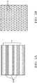
- Figs. 2A-2B illustrate portions of the base 16 within the cavity 30 before the surface-skin is removed.
- the portion of the base 16 within the cavity 30 is cast with a planar-surface (not shown).
- the portion of the base 16 within the cavity 30 is cast with ribs 42 forming an undulating-surface, wherein when the surface-skin is removed the exposed-surface 36 is characterized as having undulations 44.
- dimples 46 i.e. depressions, embossments, etc.
- Other structures may be formed in the base 16 within the cavity 30 by bead-blasting or other means that also create undulations 44 in the exposed-surface 36.
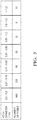
- Fig. 3 is a table that illustrates an example of a preferred pore-size-distribution that may be developed in the porous-structure 32 based on a rate-of-casting, entrained gas, and other casting parameters that will be appreciated by those in the art.
- a pore diameter range and the number of pores in the respective range are listed.
- the assembly 10 also includes a heat-transfer-fluid 48 disposed within the cavity 30 and occupies a portion of the cavity 30 (i.e. the cavity 30 is not completely filled with the heat-transfer-fluid 48).
- the heat-transfer-fluid 48 may be any heat-transfer-fluid 48 with a boiling-point suited to the thermal environment of the application.
- the heat-transfer-fluid 48 is acetone. In other applications a mixture of water and ethylene glycol may be used for the heat-transfer-fluid 48.
- the heat-transfer-fluid 48 is heated by the second-surface 20 from the heat conducted away from the electrical-device 12.
- the heat-transfer-fluid 48 evaporates, transports across the porous-structure 32 and across the void 34 in the cavity 30, and condenses on the third-surface 24 thereby distributing the heat over the third-surface 24.
- the condensed heat-transfer-fluid 48 returns to the porous-structure 32 that acts as a wicking-plane to direct the liquid heat-transfer-fluid 48 back to the desired heat producing location (e.g. the locations of greatest heat conduction from the electrical-device 12).
- This closed-system i.e. sealed system
- the fourth-surface 26 is configured to dissipate the heat generated by the electrical-device 12 to a surrounding environment 50, and in one embodiment includes cooling-fins 52 extending beyond the fourth-surface 26.
- an electrical-circuit-assembly 10 (the assembly 10 is provided.
- the assembly 10 is an improvement over other electrical-circuit-assemblies because the assembly 10 passively transfers heat away from the electrical-device 12 at a greater rate than the typical solid aluminum-heat-sink.
- first contact could be termed a second contact
- second contact could be termed a first contact
- the first contact and the second contact are both contacts, but they are not the same contact.
- the terminology used in the description of the various described embodiments herein is for the purpose of describing particular embodiments only and is not intended to be limiting. As used in the description of the various described embodiments and the appended claims, the singular forms "a”, “an” and “the” are intended to include the plural forms as well, unless the context clearly indicates otherwise. It will also be understood that the term “and/or” as used herein refers to and encompasses any and all possible combinations of one or more of the associated listed items.
- the phrase “if it is determined” or “if [a stated condition or event] is detected” is, optionally, construed to mean “upon determining” or “in response to determining” or “upon detecting [the stated condition or event]” or “in response to detecting [the stated condition or event],” depending on the context.
Landscapes
- Engineering & Computer Science (AREA)
- Microelectronics & Electronic Packaging (AREA)
- Physics & Mathematics (AREA)
- Thermal Sciences (AREA)
- Cooling Or The Like Of Semiconductors Or Solid State Devices (AREA)
- Cooling Or The Like Of Electrical Apparatus (AREA)
Abstract
Description
- This application claims the benefit of
U.S. Patent Application No. 16/026,261, filed July 3, 2018 , the entire disclosure of which is hereby incorporated herein by reference. This application also claims the benefit ofU.S. Provisional Patent Application No. 62/692,979 filed July 2, 2018 - This disclosure generally relates to an electrical-circuit assembly, and more particularly relates to an electrical-circuit assembly with a heat-sink.
- Autonomous ride-sharing-vehicles and/or autonomous mobility-vehicles may be required to travel over distances that may be greater than their designed operating range. Additionally, these vehicles may not be designed with the safety features of a typical passenger vehicle.
- The present invention proposes to solve the above mentioned problem by providing an electrical-circuit assembly comprising a heat-sink having a base having a first-surface and a second-surface opposite the first-surface, the first-surface in thermal communication with an electrical-device; a lid having a third-surface and a fourth-surface opposite the third-surface, the lid arranged so the third-surface faces toward the second-surface; side-walls disposed between the base and the lid extending from the second-surface to the third-surface, wherein the base, the lid, and the side-walls cooperate to define a cavity; a porous-structure extending from the second-surface toward the third-surface, the porous-structure terminating a portion of a distance between the second-surface and the third-surface thereby defining a void between the porous-structure and the third-surface; the void extending along the entire porous-structure and terminating at the side-walls; the porous-structure having a contiguous-porosity network; and a heat-transfer-fluid disposed within the cavity.
- According to other advantageous features of the present invention:
- the heat-transfer-fluid occupies a portion of the cavity;
- a depth of the porous-structure is in a range from about 1.0 millimeters to about 4.0 millimeters;
- the fourth-surface is configured to dissipate heat generated by the electrical-device to a surrounding environment;
- the fourth-surface includes cooling-fins extending beyond the fourth-surface;
- the porous-structure is characterized by a percent-porosity in a range from about 48 percent to about 74 percent;
- the porous-structure defines an exposed-surface, and the exposed-surface is characterized as having undulations; the exposed-surface adjacent to the void;
- the exposed-surface is a planar-surface;
- the exposed-surface has undulations;
- the undulations include ribs;
- the undulations include dimples;
- the base, the side-walls, and the porous-structure are integrally formed of a die cast aluminum alloy.
- The present invention proposes to solve the above mentioned problem by providing a heat-sink comprising a base having a first-surface and a second-surface opposite the first-surface, the first-surface configured for thermal communication with an electrical-device; a lid having a third-surface and a fourth-surface opposite the third-surface, the lid arranged so the third-surface faces toward the second-surface; side-walls disposed between the base and the lid extending from the second-surface to the third-surface, wherein the base, the lid, and the side-walls cooperate to define a cavity; a single porous-structure extending from the second-surface toward the third-surface, the single porous-structure terminating a portion of a distance between the second-surface and the third-surface thereby defining a void between the single porous-structure and the third-surface; the base, the side-walls, and the porous-structure integrally formed of a common material; the single porous-structure characterized as having a contiguous-porosity network; and a heat-transfer-fluid disposed within the cavity.
- According to other advantageous features of the present invention:
- the single porous-structure defines an exposed-surface adjacent to the void;
- the exposed-surface is a planar-surface;
- the exposed-surface has undulations;
- the undulations include ribs;
- the undulations include dimples;
- the base, the side-walls, and the single porous-structure are integrally formed of a die cast aluminum alloy.
- The present invention will now be described, by way of example with reference to the accompanying drawings, in which:
-
Fig. 1 is a section view of an illustration of an electrical-circuit assembly in accordance with one embodiment; -
Fig. 2A is an illustration of ribs cast into a base of the electrical-circuit assembly ofFig. 1 in accordance with one embodiment; -
Fig. 2B is an illustration of dimples cast into the base of the electrical-circuit assembly ofFig. 1 in accordance with one embodiment; and -
Fig. 3 is a table illustrating a pore size distribution of a porous-structure of the electrical-circuit assembly ofFig. 1 in accordance with one embodiment. - Reference will now be made in detail to embodiments, examples of which are illustrated in the accompanying drawings. In the following detailed description, numerous specific details are set forth in order to provide a thorough understanding of the various described embodiments. However, it will be apparent to one of ordinary skill in the art that the various described embodiments may be practiced without these specific details. In other instances, well-known methods, procedures, components, circuits, and networks have not been described in detail so as not to unnecessarily obscure aspects of the embodiments.
-
Fig. 1 illustrates is a section view of an electrical-circuit assembly 10, hereafter referred to as theassembly 10. As will be described in more detail below, theassembly 10 is an improvement on previous electrical-circuit-assemblies because theassembly 10 passively cools an electrical-device 12. As used herein, the term "passively" means that no mechanical pump or fan mechanism is used to cool the assembly, that would typically require an external power source, add cost, and increase a package-size. - The
assembly 10 includes the electrical-device 12. The electrical-device 12 may be any electrical-device 12 that may benefit from cooling (i.e. heat removal) during operation, including, but not limited to, capacitors, resistors, inductors, amplifiers, microprocessors, etc., or any combination thereof, as will be recognized by one skilled in the art. The electrical-device 12 may include printed-circuit-boards formed of epoxy-resins, polyimide-resins, and/or ceramics. The electrical-device 12 may be a vehicle-controller, such as that used for controlling an autonomous-vehicle, which typically generates more heat than a typical vehicle-controller, due to the increased microprocessor demands required for autonomous driving. - The
assembly 10 also includes a heat-sink 14 operable to remove heat from the electrical-device 12. The heat-sink 14 includes abase 16 having a first-surface 18 and a second-surface 20 opposite the first-surface 18. Thebase 16 may be formed of any material that is heat-conducting. In the example illustrated inFig. 1 , thebase 16 is formed of an aluminum-alloy that is die-cast. The first-surface 18 of thebase 16 is in thermal communication with the electrical-device 12. That is, the first-surface 18 provides a path for heat to be conducted away from the electrical-device 12. - The heat-
sink 14 also includes alid 22 having a third-surface 24 and a fourth-surface 26 opposite the third-surface 24. In the example illustrated inFig. 1 thelid 22 is formed of an aluminum-alloy that is die-cast. Thelid 22 is arranged so the third-surface 24 faces toward the second-surface 20. Thelid 22 may be attached to thebase 16 by any method to preferably form a hermetic-seal, including welding, soldering, adhesives, etc., and in the example illustrated inFig. 1 , thelid 22 is friction stir welded to thebase 16 forming a metallurgical bond. - The heat-
sink 14 also includes side-walls 28 disposed between thebase 16 and thelid 22 extending from the second-surface 20 to the third-surface 24 and define a perimeter of the heat-sink 14. Thebase 16, thelid 22, and the side-walls 28 cooperate to define acavity 30. - The heat-
sink 14 also includes a porous-structure 32 extending from the second-surface 20 toward the third-surface 24. The porous-structure 32 terminates (i.e. ends, stops, etc.) a portion of a distance between the second-surface 20 and the third-surface 24 thereby defining avoid 34 between the porous-structure 32 and the third-surface 24. That is, the porous-structure 32 does not completely fill thecavity 30 and leaves thevoid 34 between the porous-structure 32 and the third-surface 24. Thebase 16, the side-walls 28, and the porous-structure 32 are integrally formed of a common material (e.g. die-cast aluminum-alloy). That is, thebase 16, the side-walls 28, and the porous-structure 32 are formed as one unit during the die-casting process and are not formed as a result of welding separate die-case components together, or sintering powdered metals to create the porous-structure 32. The porous-structure 32 is characterized as having a contiguous-porosity network. That is, fluidic communication exists throughout the entire porous-structure 32 enabling a flow of fluids through the porous-structure 32. In contrast, the second-surface 20, the side-walls 28, and the third-surface 24 inhibit the flow of fluid through their respective sections. The porous-structure 32 is formed by controlling porosity in the base 16 during the die-casting process, as will be appreciated by those skilled in the art of die-casting. The porous-structure 32 defines an exposed-surface 36 that faces the third-surface 24. The exposed-surface 36 is created by removing a portion of a surface-skin, formed during die-casting, from the base 16 by mechanical and/or chemical processing. Adepth 38 of the porous-structure 32 is in a range from about 1.0 millimeters to about 4.0 millimeters. The porous-structure 32 is characterized by a percent-porosity 40 in a range from about 48-percent to about 74-percent. -
Figs. 2A-2B illustrate portions of thebase 16 within thecavity 30 before the surface-skin is removed. In one embodiment, the portion of thebase 16 within thecavity 30 is cast with a planar-surface (not shown). In another embodiment (seeFig. 2A ), the portion of thebase 16 within thecavity 30 is cast withribs 42 forming an undulating-surface, wherein when the surface-skin is removed the exposed-surface 36 is characterized as havingundulations 44. In yet another embodiment (seeFig. 2B ), dimples 46 (i.e. depressions, embossments, etc.) are cast into the portion of thebase 16 within thecavity 30 to create the undulating-surface and may increase the heat conduction in a direction normal to the second-surface 20. Other structures may be formed in thebase 16 within thecavity 30 by bead-blasting or other means that also createundulations 44 in the exposed-surface 36. -
Fig. 3 is a table that illustrates an example of a preferred pore-size-distribution that may be developed in the porous-structure 32 based on a rate-of-casting, entrained gas, and other casting parameters that will be appreciated by those in the art. A pore diameter range and the number of pores in the respective range are listed. - Referring back to
Fig. 1 , theassembly 10 also includes a heat-transfer-fluid 48 disposed within thecavity 30 and occupies a portion of the cavity 30 (i.e. thecavity 30 is not completely filled with the heat-transfer-fluid 48). The heat-transfer-fluid 48 may be any heat-transfer-fluid 48 with a boiling-point suited to the thermal environment of the application. In the example illustrated inFig. 1 , the heat-transfer-fluid 48 is acetone. In other applications a mixture of water and ethylene glycol may be used for the heat-transfer-fluid 48. The heat-transfer-fluid 48 is heated by the second-surface 20 from the heat conducted away from the electrical-device 12. The heat-transfer-fluid 48 evaporates, transports across the porous-structure 32 and across the void 34 in thecavity 30, and condenses on the third-surface 24 thereby distributing the heat over the third-surface 24. The condensed heat-transfer-fluid 48 returns to the porous-structure 32 that acts as a wicking-plane to direct the liquid heat-transfer-fluid 48 back to the desired heat producing location (e.g. the locations of greatest heat conduction from the electrical-device 12). This closed-system (i.e. sealed system) is beneficial because it does not require the heat-transfer-fluid 48 to be replenished, or transferred into and/or out of thecavity 30. Experimentation by the inventors indicates that the heat-transfer capability of theassembly 10 as describe above is in excess of 40,000 Watts/meter-Kelvin (40,000 W/mK), compared to only 140 W/mK for a typical solid aluminum-heat-sink. - Referring again to
Fig. 1 , the fourth-surface 26 is configured to dissipate the heat generated by the electrical-device 12 to a surroundingenvironment 50, and in one embodiment includes cooling-fins 52 extending beyond the fourth-surface 26. - Accordingly, an electrical-circuit-assembly 10 (the
assembly 10 is provided. Theassembly 10 is an improvement over other electrical-circuit-assemblies because theassembly 10 passively transfers heat away from the electrical-device 12 at a greater rate than the typical solid aluminum-heat-sink. - While this invention has been described in terms of the preferred embodiments thereof, it is not intended to be so limited, but rather only to the extent set forth in the claims that follow. "One or more" includes a function being performed by one element, a function being performed by more than one element, e.g., in a distributed fashion, several functions being performed by one element, several functions being performed by several elements, or any combination of the above. It will also be understood that, although the terms first, second, etc. are, in some instances, used herein to describe various elements, these elements should not be limited by these terms. These terms are only used to distinguish one element from another. For example, a first contact could be termed a second contact, and, similarly, a second contact could be termed a first contact, without departing from the scope of the various described embodiments. The first contact and the second contact are both contacts, but they are not the same contact. The terminology used in the description of the various described embodiments herein is for the purpose of describing particular embodiments only and is not intended to be limiting. As used in the description of the various described embodiments and the appended claims, the singular forms "a", "an" and "the" are intended to include the plural forms as well, unless the context clearly indicates otherwise. It will also be understood that the term "and/or" as used herein refers to and encompasses any and all possible combinations of one or more of the associated listed items. It will be further understood that the terms "includes," "including," "comprises," and/or "comprising," when used in this specification, specify the presence of stated features, integers, steps, operations, elements, and/or components, but do not preclude the presence or addition of one or more other features, integers, steps, operations, elements, components, and/or groups thereof. As used herein, the term "if' is, optionally, construed to mean "when" or "upon" or "in response to determining" or "in response to detecting," depending on the context. Similarly, the phrase "if it is determined" or "if [a stated condition or event] is detected" is, optionally, construed to mean "upon determining" or "in response to determining" or "upon detecting [the stated condition or event]" or "in response to detecting [the stated condition or event]," depending on the context.
Claims (15)
- An electrical-circuit assembly (10), the assembly (10) comprising:
a heat-sink (14) having:a base (16) having a first-surface (18) and a second-surface (20) opposite the first-surface (18), the first-surface (18) in thermal communication with an electrical-device (12);a lid (22) having a third-surface (24) and a fourth-surface (26) opposite the third-surface (24), the lid (22) arranged so the third-surface (24) faces toward the second-surface (20);side-walls (28) disposed between the base (16) and the lid (22) extending from the second-surface (20) to the third-surface (24), wherein the base (16), the lid (22), and the side-walls (28) cooperate to define a cavity (30);a porous-structure (32) extending from the second-surface (20) toward the third-surface (24), the porous-structure (32) terminating a portion of a distance between the second-surface (20) and the third-surface (24) thereby defining a void (34) between the porous-structure (32) and the third-surface (24);
the void (34) extending along the entire porous-structure (32) and terminating at the side-walls (28);the porous-structure (32) having a contiguous-porosity network; anda heat-transfer-fluid (48) disposed within the cavity (30). - The assembly (10) in accordance with claim 1, wherein the heat-transfer-fluid (48) occupies a portion of the cavity (30).
- The assembly (10) in accordance with any one of the preceding claims, wherein a depth (38) of the porous-structure (32) is in a range from about 1.0 millimeters to about 4.0 millimeters.
- The assembly (10) in accordance with any one of the preceding claims, wherein the fourth-surface (26) is configured to dissipate heat generated by the electrical-device (12) to a surrounding environment (50).
- The assembly (10) in accordance with any one of the preceding claims, wherein the fourth-surface (26) includes cooling-fins (52) extending beyond the fourth-surface (26).
- The assembly (10) in accordance with any one of the preceding claims, wherein the porous-structure (32) has a percent-porosity (40) in a range from about 48 percent to about 74 percent.
- The assembly (10) in accordance with any one of the preceding claims, wherein the porous-structure (32) defines an exposed-surface (36), the exposed-surface (36) adjacent to the void (34).
- The assembly (10) in accordance with claim 7, wherein the exposed-surface (36) is a planar-surface.
- A heat-sink (14) comprising:a base (16) having a first-surface (18) and a second-surface (20) opposite the first-surface (18), the first-surface (18) configured for thermal communication with an electrical-device (12);a lid (22) having a third-surface (24) and a fourth-surface (26) opposite the third-surface (24), the lid (22) arranged so the third-surface (24) faces toward the second-surface (20);side-walls (28) disposed between the base (16) and the lid (22) extending from the second-surface (20) to the third-surface (24), wherein the base (16), the lid (22), and the side-walls (28) cooperate to define a cavity (30);a single porous-structure (32) extending from the second-surface (20) toward the third-surface (24), the single porous-structure (32) terminating a portion of a distance between the second-surface (20) and the third-surface (24) thereby defining a void (34) between the single porous-structure (32) and the third-surface (24);the single porous-structure (32) having a contiguous-porosity network; anda heat-transfer-fluid (48) disposed within the cavity (30).
- The heat-sink (14) in accordance with claim 9, wherein the single porous-structure (32) defines an exposed-surface (36) adjacent to the void (34).
- The heat-sink (14) in accordance with claim 10, wherein the exposed-surface (36) is a planar-surface.
- The heat-sink (14) in accordance with claim 10, wherein and the exposed-surface (36) has undulations (44).
- The heat-sink (14) in accordance with claim 12, wherein the undulations (44) include ribs (42).
- The heat-sink (14) in accordance with claim 12 or 13, wherein the undulations (44) include dimples (46).
- The heat-sink (14) in accordance with any one of claims 9 to 14, wherein the base (16), the side-walls (28), and the single porous-structure (32) are integrally formed of a die cast aluminum alloy.
Applications Claiming Priority (2)
| Application Number | Priority Date | Filing Date | Title |
|---|---|---|---|
| US201862692979P | 2018-07-02 | 2018-07-02 | |
| US16/026,261 US10849217B2 (en) | 2018-07-02 | 2018-07-03 | Electrical-circuit assembly with heat-sink |
Publications (2)
| Publication Number | Publication Date |
|---|---|
| EP3592123A1 true EP3592123A1 (en) | 2020-01-08 |
| EP3592123B1 EP3592123B1 (en) | 2023-06-28 |
Family
ID=66998096
Family Applications (1)
| Application Number | Title | Priority Date | Filing Date |
|---|---|---|---|
| EP19180619.9A Active EP3592123B1 (en) | 2018-07-02 | 2019-06-17 | Electrical-circuit assembly with heat-sink |
Country Status (3)
| Country | Link |
|---|---|
| US (1) | US10849217B2 (en) |
| EP (1) | EP3592123B1 (en) |
| CN (1) | CN110678036A (en) |
Families Citing this family (8)
| Publication number | Priority date | Publication date | Assignee | Title |
|---|---|---|---|---|
| US11121058B2 (en) | 2019-07-24 | 2021-09-14 | Aptiv Technologies Limited | Liquid cooled module with device heat spreader |
| US11217505B2 (en) * | 2019-09-10 | 2022-01-04 | Aptiv Technologies Limited | Heat exchanger for electronics |
| US11632860B2 (en) * | 2019-10-25 | 2023-04-18 | Infineon Technologies Ag | Power electronic assembly and method of producing thereof |
| US11506458B2 (en) * | 2020-09-10 | 2022-11-22 | Amulaire Thermal Technology, Inc. | Enclosed heat sink with side wall structure |
| US11382205B2 (en) * | 2020-09-16 | 2022-07-05 | Aptiv Technologies Limited | Heatsink shield with thermal-contact dimples for thermal-energy distribution in a radar assembly |
| FR3129266A1 (en) * | 2021-11-16 | 2023-05-19 | Valeo Systemes De Controle Moteur | Electronic assembly featuring an improved cooling system |
| US20230408636A1 (en) * | 2022-06-16 | 2023-12-21 | Aptiv Technologies Limited | Metalized plastic housing enclosure heat sink |
| WO2024130625A1 (en) * | 2022-12-22 | 2024-06-27 | 华为技术有限公司 | Heat dissipation apparatus, electronic device and vehicle |
Citations (6)
| Publication number | Priority date | Publication date | Assignee | Title |
|---|---|---|---|---|
| US6082443A (en) * | 1997-02-13 | 2000-07-04 | The Furukawa Electric Co., Ltd. | Cooling device with heat pipe |
| US20070025085A1 (en) * | 2005-07-29 | 2007-02-01 | Hon Hai Precision Industry Co., Ltd. | Heat sink |
| US20160343639A1 (en) * | 2015-05-22 | 2016-11-24 | Micron Technology, Inc. | Seminconductor device assembly with vapor chamber |
| WO2017100568A2 (en) * | 2015-12-11 | 2017-06-15 | Purdue Research Foundation | Vapor chamber heat spreaders and methods of manufacturing thereof |
| US20170318702A1 (en) * | 2016-04-29 | 2017-11-02 | Intel Corporation | Wickless capillary driven constrained vapor bubble heat pipes for application in electronic devices with various system platforms |
| WO2018003957A1 (en) * | 2016-07-01 | 2018-01-04 | 古河電気工業株式会社 | Vapor chamber |
Family Cites Families (38)
| Publication number | Priority date | Publication date | Assignee | Title |
|---|---|---|---|---|
| DE4326207A1 (en) * | 1992-10-06 | 1994-04-07 | Hewlett Packard Co | Mechanically floating multi-chip substrate |
| US6690578B2 (en) * | 2000-02-02 | 2004-02-10 | Rittal Gmbh & Co. Kg | Cooling device |
| BRPI0100051B1 (en) * | 2001-01-11 | 2016-11-29 | Brasil Compressores Sa | electronic device enclosure |
| US7775261B2 (en) * | 2002-02-26 | 2010-08-17 | Mikros Manufacturing, Inc. | Capillary condenser/evaporator |
| JP3844467B2 (en) * | 2003-01-08 | 2006-11-15 | 沖電気工業株式会社 | Semiconductor device and manufacturing method thereof |
| US6945317B2 (en) * | 2003-04-24 | 2005-09-20 | Thermal Corp. | Sintered grooved wick with particle web |
| US6994152B2 (en) * | 2003-06-26 | 2006-02-07 | Thermal Corp. | Brazed wick for a heat transfer device |
| EP1639628A4 (en) * | 2003-06-26 | 2007-12-26 | Thermal Corp | Heat transfer device and method of making same |
| JP4391366B2 (en) * | 2003-09-12 | 2009-12-24 | 古河電気工業株式会社 | Heat sink with heat pipe and method of manufacturing the same |
| US6901994B1 (en) * | 2004-01-05 | 2005-06-07 | Industrial Technology Research Institute | Flat heat pipe provided with means to enhance heat transfer thereof |
| CN1864895A (en) | 2005-05-17 | 2006-11-22 | 上海众汇泡沫铝材有限公司 | Process for preparing through-hole foam aluminium plate |
| CN100420912C (en) | 2005-06-08 | 2008-09-24 | 财团法人工业技术研究院 | Composite capillary structure of heat transfer component |
| CN100464411C (en) * | 2005-10-20 | 2009-02-25 | 富准精密工业(深圳)有限公司 | Light-emitting diode packaging structure and packaging method |
| TWM299458U (en) * | 2006-04-21 | 2006-10-11 | Taiwan Microloops Corp | Heat spreader with composite micro-structure |
| US8462508B2 (en) * | 2007-04-30 | 2013-06-11 | Hewlett-Packard Development Company, L.P. | Heat sink with surface-formed vapor chamber base |
| TWI402952B (en) * | 2007-09-27 | 2013-07-21 | 三洋電機股份有限公司 | Circuit device and method of manufacturing same |
| US20090151905A1 (en) * | 2007-12-14 | 2009-06-18 | Fu Zhun Precision Industry (Shen Zhen) Co., Ltd. | Heat sink with vapor chamber |
| TWM347809U (en) * | 2008-05-26 | 2008-12-21 | Xu xiu cang | Fast temperature-averaging heat conductive device |
| US20100071879A1 (en) * | 2008-09-19 | 2010-03-25 | Foxconn Technology Co., Ltd. | Method for manufacturing a plate-type heat pipe and a plate-type heat pipe obtained thereby |
| CN101865370B (en) * | 2009-04-16 | 2013-08-07 | 富准精密工业(深圳)有限公司 | Light-emitting diode lamp |
| US20100309940A1 (en) * | 2009-06-04 | 2010-12-09 | Hsing-Chung Lee | High power laser package with vapor chamber |
| TW201116794A (en) * | 2009-11-10 | 2011-05-16 | Pegatron Corp | Vapor chamber and manufacturing method thereof |
| US8773854B2 (en) * | 2011-04-25 | 2014-07-08 | Google Inc. | Thermosiphon systems for electronic devices |
| CN102811589A (en) * | 2011-05-31 | 2012-12-05 | 富准精密工业(深圳)有限公司 | Electronic device |
| US8857502B2 (en) * | 2011-07-26 | 2014-10-14 | Kunshan Jue-Chung Electronics Co., Ltd. | Vapor chamber having heated protrusion |
| WO2013020106A1 (en) * | 2011-08-03 | 2013-02-07 | Anchor Science Llc | Dynamic thermal interface material |
| CN202485508U (en) | 2011-11-30 | 2012-10-10 | 夏邦杰 | Two-phase cooling fin |
| EP2713132A1 (en) * | 2012-09-26 | 2014-04-02 | Alcatel Lucent | A vapor-based heat transfer apparatus |
| JP5789684B2 (en) * | 2014-01-10 | 2015-10-07 | 株式会社フジクラ | Vapor chamber |
| CN203807965U (en) | 2014-04-16 | 2014-09-03 | 上海然贝声学环保工程有限公司 | Foamed aluminum sound absorption and insulation screen |
| US9735130B2 (en) * | 2014-08-29 | 2017-08-15 | Taiwan Semiconductor Manufacturing Company, Ltd. | Chip packages and methods of manufacture thereof |
| TWM517812U (en) | 2015-09-23 | 2016-02-21 | Taiwan Microloops Corp | Vapor chamber and upper shell member thereof |
| TWI639806B (en) * | 2016-02-05 | 2018-11-01 | 業強科技股份有限公司 | Thermal conduction device and method of manufacturing same |
| US10670352B2 (en) * | 2016-05-23 | 2020-06-02 | Pimems, Inc. | High performance two-phase cooling apparatus for portable applications |
| CN106793685A (en) | 2016-12-09 | 2017-05-31 | 淳铭散热科技股份有限公司 | A kind of composite heat dissipation device |
| CN106653713B (en) * | 2016-12-23 | 2019-06-14 | 北京工业大学 | A self-optimizing heat dissipation dual-chamber heat pipe |
| WO2018144020A1 (en) * | 2017-02-03 | 2018-08-09 | Hewlett-Packard Development Company, L.P. | Thermal control with vapor and isolation chambers |
| CN107695318B (en) | 2017-09-29 | 2019-04-30 | 重庆理工大学 | A kind of foam magnesium sandwich panel and semi-solid thixotropic seepage casting method |
-
2018
- 2018-07-03 US US16/026,261 patent/US10849217B2/en active Active
-
2019
- 2019-06-17 EP EP19180619.9A patent/EP3592123B1/en active Active
- 2019-06-24 CN CN201910547500.XA patent/CN110678036A/en active Pending
Patent Citations (7)
| Publication number | Priority date | Publication date | Assignee | Title |
|---|---|---|---|---|
| US6082443A (en) * | 1997-02-13 | 2000-07-04 | The Furukawa Electric Co., Ltd. | Cooling device with heat pipe |
| US20070025085A1 (en) * | 2005-07-29 | 2007-02-01 | Hon Hai Precision Industry Co., Ltd. | Heat sink |
| US20160343639A1 (en) * | 2015-05-22 | 2016-11-24 | Micron Technology, Inc. | Seminconductor device assembly with vapor chamber |
| WO2017100568A2 (en) * | 2015-12-11 | 2017-06-15 | Purdue Research Foundation | Vapor chamber heat spreaders and methods of manufacturing thereof |
| US20170318702A1 (en) * | 2016-04-29 | 2017-11-02 | Intel Corporation | Wickless capillary driven constrained vapor bubble heat pipes for application in electronic devices with various system platforms |
| WO2018003957A1 (en) * | 2016-07-01 | 2018-01-04 | 古河電気工業株式会社 | Vapor chamber |
| US20190141855A1 (en) * | 2016-07-01 | 2019-05-09 | Furukawa Electric Co., Ltd. | Vapor chamber |
Also Published As
| Publication number | Publication date |
|---|---|
| US20200008291A1 (en) | 2020-01-02 |
| US10849217B2 (en) | 2020-11-24 |
| EP3592123B1 (en) | 2023-06-28 |
| CN110678036A (en) | 2020-01-10 |
Similar Documents
| Publication | Publication Date | Title |
|---|---|---|
| EP3592123B1 (en) | Electrical-circuit assembly with heat-sink | |
| US9681580B2 (en) | Method of producing an enhanced base plate | |
| EP3115728B1 (en) | Cooling apparatus and method | |
| US6257310B1 (en) | Method for making heat sink vacuum | |
| US10830299B2 (en) | Brake disc and method for producing same | |
| CN108029219B (en) | Liquid cooled cold plate and method of making same | |
| EP2142827B1 (en) | High speed flywheel | |
| EP2884130A1 (en) | Fluid-type deceleration device | |
| JP2011058750A (en) | Heat accumulator and method for manufacturing heat accumulator | |
| US6528132B1 (en) | Phase change cooling of brake components | |
| CN102263464B (en) | Method, mold and mold system for forming a rotor | |
| JPH09121557A (en) | Electronic device cooling structure for rotating equipment and manufacturing method thereof | |
| EP3016139B1 (en) | Planar heat cup with confined reservoir for electronic power component | |
| EP4117151A1 (en) | Electric machine cooling | |
| CN107654381B (en) | From cooling vacuum pump system | |
| CN109219917B (en) | Electric motor with thermosiphon | |
| JP2016102616A (en) | Heat pipe and cooling mechanism of rotary machine | |
| JP2005228948A (en) | heatsink | |
| US20050279595A1 (en) | Refrigerant-cooled rotor | |
| CN114175235A (en) | Cooling device | |
| EP3650340A1 (en) | Rotor brake overheat management device | |
| EP1350983A3 (en) | System for controlling the temperature of a vehicle driveline component utilising forced air flow | |
| CN104080574A (en) | Vertical lathe | |
| CN112292915A (en) | Method for manufacturing housing for electronic device | |
| JP2008227342A (en) | Semiconductor device |
Legal Events
| Date | Code | Title | Description |
|---|---|---|---|
| PUAI | Public reference made under article 153(3) epc to a published international application that has entered the european phase |
Free format text: ORIGINAL CODE: 0009012 |
|
| STAA | Information on the status of an ep patent application or granted ep patent |
Free format text: STATUS: THE APPLICATION HAS BEEN PUBLISHED |
|
| AK | Designated contracting states |
Kind code of ref document: A1 Designated state(s): AL AT BE BG CH CY CZ DE DK EE ES FI FR GB GR HR HU IE IS IT LI LT LU LV MC MK MT NL NO PL PT RO RS SE SI SK SM TR |
|
| AX | Request for extension of the european patent |
Extension state: BA ME |
|
| STAA | Information on the status of an ep patent application or granted ep patent |
Free format text: STATUS: REQUEST FOR EXAMINATION WAS MADE |
|
| 17P | Request for examination filed |
Effective date: 20200702 |
|
| RBV | Designated contracting states (corrected) |
Designated state(s): AL AT BE BG CH CY CZ DE DK EE ES FI FR GB GR HR HU IE IS IT LI LT LU LV MC MK MT NL NO PL PT RO RS SE SI SK SM TR |
|
| STAA | Information on the status of an ep patent application or granted ep patent |
Free format text: STATUS: EXAMINATION IS IN PROGRESS |
|
| 17Q | First examination report despatched |
Effective date: 20210705 |
|
| GRAP | Despatch of communication of intention to grant a patent |
Free format text: ORIGINAL CODE: EPIDOSNIGR1 |
|
| STAA | Information on the status of an ep patent application or granted ep patent |
Free format text: STATUS: GRANT OF PATENT IS INTENDED |
|
| RAP3 | Party data changed (applicant data changed or rights of an application transferred) |
Owner name: APTIV TECHNOLOGIES LIMITED |
|
| INTG | Intention to grant announced |
Effective date: 20230317 |
|
| GRAS | Grant fee paid |
Free format text: ORIGINAL CODE: EPIDOSNIGR3 |
|
| GRAA | (expected) grant |
Free format text: ORIGINAL CODE: 0009210 |
|
| STAA | Information on the status of an ep patent application or granted ep patent |
Free format text: STATUS: THE PATENT HAS BEEN GRANTED |
|
| AK | Designated contracting states |
Kind code of ref document: B1 Designated state(s): AL AT BE BG CH CY CZ DE DK EE ES FI FR GB GR HR HU IE IS IT LI LT LU LV MC MK MT NL NO PL PT RO RS SE SI SK SM TR |
|
| REG | Reference to a national code |
Ref country code: CH Ref legal event code: EP |
|
| REG | Reference to a national code |
Ref country code: AT Ref legal event code: REF Ref document number: 1583892 Country of ref document: AT Kind code of ref document: T Effective date: 20230715 |
|
| REG | Reference to a national code |
Ref country code: IE Ref legal event code: FG4D |
|
| REG | Reference to a national code |
Ref country code: DE Ref legal event code: R096 Ref document number: 602019031584 Country of ref document: DE |
|
| REG | Reference to a national code |
Ref country code: LT Ref legal event code: MG9D |
|
| PG25 | Lapsed in a contracting state [announced via postgrant information from national office to epo] |
Ref country code: SE Free format text: LAPSE BECAUSE OF FAILURE TO SUBMIT A TRANSLATION OF THE DESCRIPTION OR TO PAY THE FEE WITHIN THE PRESCRIBED TIME-LIMIT Effective date: 20230628 Ref country code: NO Free format text: LAPSE BECAUSE OF FAILURE TO SUBMIT A TRANSLATION OF THE DESCRIPTION OR TO PAY THE FEE WITHIN THE PRESCRIBED TIME-LIMIT Effective date: 20230928 |
|
| REG | Reference to a national code |
Ref country code: NL Ref legal event code: MP Effective date: 20230628 |
|
| REG | Reference to a national code |
Ref country code: AT Ref legal event code: MK05 Ref document number: 1583892 Country of ref document: AT Kind code of ref document: T Effective date: 20230628 |
|
| PG25 | Lapsed in a contracting state [announced via postgrant information from national office to epo] |
Ref country code: RS Free format text: LAPSE BECAUSE OF FAILURE TO SUBMIT A TRANSLATION OF THE DESCRIPTION OR TO PAY THE FEE WITHIN THE PRESCRIBED TIME-LIMIT Effective date: 20230628 Ref country code: NL Free format text: LAPSE BECAUSE OF FAILURE TO SUBMIT A TRANSLATION OF THE DESCRIPTION OR TO PAY THE FEE WITHIN THE PRESCRIBED TIME-LIMIT Effective date: 20230628 Ref country code: LV Free format text: LAPSE BECAUSE OF FAILURE TO SUBMIT A TRANSLATION OF THE DESCRIPTION OR TO PAY THE FEE WITHIN THE PRESCRIBED TIME-LIMIT Effective date: 20230628 Ref country code: LT Free format text: LAPSE BECAUSE OF FAILURE TO SUBMIT A TRANSLATION OF THE DESCRIPTION OR TO PAY THE FEE WITHIN THE PRESCRIBED TIME-LIMIT Effective date: 20230628 Ref country code: HR Free format text: LAPSE BECAUSE OF FAILURE TO SUBMIT A TRANSLATION OF THE DESCRIPTION OR TO PAY THE FEE WITHIN THE PRESCRIBED TIME-LIMIT Effective date: 20230628 Ref country code: GR Free format text: LAPSE BECAUSE OF FAILURE TO SUBMIT A TRANSLATION OF THE DESCRIPTION OR TO PAY THE FEE WITHIN THE PRESCRIBED TIME-LIMIT Effective date: 20230929 |
|
| PG25 | Lapsed in a contracting state [announced via postgrant information from national office to epo] |
Ref country code: FI Free format text: LAPSE BECAUSE OF FAILURE TO SUBMIT A TRANSLATION OF THE DESCRIPTION OR TO PAY THE FEE WITHIN THE PRESCRIBED TIME-LIMIT Effective date: 20230628 |
|
| PG25 | Lapsed in a contracting state [announced via postgrant information from national office to epo] |
Ref country code: SK Free format text: LAPSE BECAUSE OF FAILURE TO SUBMIT A TRANSLATION OF THE DESCRIPTION OR TO PAY THE FEE WITHIN THE PRESCRIBED TIME-LIMIT Effective date: 20230628 |
|
| PG25 | Lapsed in a contracting state [announced via postgrant information from national office to epo] |
Ref country code: ES Free format text: LAPSE BECAUSE OF FAILURE TO SUBMIT A TRANSLATION OF THE DESCRIPTION OR TO PAY THE FEE WITHIN THE PRESCRIBED TIME-LIMIT Effective date: 20230628 |
|
| PG25 | Lapsed in a contracting state [announced via postgrant information from national office to epo] |
Ref country code: IS Free format text: LAPSE BECAUSE OF FAILURE TO SUBMIT A TRANSLATION OF THE DESCRIPTION OR TO PAY THE FEE WITHIN THE PRESCRIBED TIME-LIMIT Effective date: 20231028 |
|
| PG25 | Lapsed in a contracting state [announced via postgrant information from national office to epo] |
Ref country code: SM Free format text: LAPSE BECAUSE OF FAILURE TO SUBMIT A TRANSLATION OF THE DESCRIPTION OR TO PAY THE FEE WITHIN THE PRESCRIBED TIME-LIMIT Effective date: 20230628 Ref country code: SK Free format text: LAPSE BECAUSE OF FAILURE TO SUBMIT A TRANSLATION OF THE DESCRIPTION OR TO PAY THE FEE WITHIN THE PRESCRIBED TIME-LIMIT Effective date: 20230628 Ref country code: RO Free format text: LAPSE BECAUSE OF FAILURE TO SUBMIT A TRANSLATION OF THE DESCRIPTION OR TO PAY THE FEE WITHIN THE PRESCRIBED TIME-LIMIT Effective date: 20230628 Ref country code: PT Free format text: LAPSE BECAUSE OF FAILURE TO SUBMIT A TRANSLATION OF THE DESCRIPTION OR TO PAY THE FEE WITHIN THE PRESCRIBED TIME-LIMIT Effective date: 20231030 Ref country code: IS Free format text: LAPSE BECAUSE OF FAILURE TO SUBMIT A TRANSLATION OF THE DESCRIPTION OR TO PAY THE FEE WITHIN THE PRESCRIBED TIME-LIMIT Effective date: 20231028 Ref country code: ES Free format text: LAPSE BECAUSE OF FAILURE TO SUBMIT A TRANSLATION OF THE DESCRIPTION OR TO PAY THE FEE WITHIN THE PRESCRIBED TIME-LIMIT Effective date: 20230628 Ref country code: EE Free format text: LAPSE BECAUSE OF FAILURE TO SUBMIT A TRANSLATION OF THE DESCRIPTION OR TO PAY THE FEE WITHIN THE PRESCRIBED TIME-LIMIT Effective date: 20230628 Ref country code: CZ Free format text: LAPSE BECAUSE OF FAILURE TO SUBMIT A TRANSLATION OF THE DESCRIPTION OR TO PAY THE FEE WITHIN THE PRESCRIBED TIME-LIMIT Effective date: 20230628 Ref country code: AT Free format text: LAPSE BECAUSE OF FAILURE TO SUBMIT A TRANSLATION OF THE DESCRIPTION OR TO PAY THE FEE WITHIN THE PRESCRIBED TIME-LIMIT Effective date: 20230628 |
|
| PG25 | Lapsed in a contracting state [announced via postgrant information from national office to epo] |
Ref country code: PL Free format text: LAPSE BECAUSE OF FAILURE TO SUBMIT A TRANSLATION OF THE DESCRIPTION OR TO PAY THE FEE WITHIN THE PRESCRIBED TIME-LIMIT Effective date: 20230628 |
|
| REG | Reference to a national code |
Ref country code: DE Ref legal event code: R097 Ref document number: 602019031584 Country of ref document: DE |
|
| PG25 | Lapsed in a contracting state [announced via postgrant information from national office to epo] |
Ref country code: DK Free format text: LAPSE BECAUSE OF FAILURE TO SUBMIT A TRANSLATION OF THE DESCRIPTION OR TO PAY THE FEE WITHIN THE PRESCRIBED TIME-LIMIT Effective date: 20230628 |
|
| PLBE | No opposition filed within time limit |
Free format text: ORIGINAL CODE: 0009261 |
|
| STAA | Information on the status of an ep patent application or granted ep patent |
Free format text: STATUS: NO OPPOSITION FILED WITHIN TIME LIMIT |
|
| PG25 | Lapsed in a contracting state [announced via postgrant information from national office to epo] |
Ref country code: IT Free format text: LAPSE BECAUSE OF FAILURE TO SUBMIT A TRANSLATION OF THE DESCRIPTION OR TO PAY THE FEE WITHIN THE PRESCRIBED TIME-LIMIT Effective date: 20230628 |
|
| 26N | No opposition filed |
Effective date: 20240402 |
|
| PG25 | Lapsed in a contracting state [announced via postgrant information from national office to epo] |
Ref country code: SI Free format text: LAPSE BECAUSE OF FAILURE TO SUBMIT A TRANSLATION OF THE DESCRIPTION OR TO PAY THE FEE WITHIN THE PRESCRIBED TIME-LIMIT Effective date: 20230628 |
|
| PG25 | Lapsed in a contracting state [announced via postgrant information from national office to epo] |
Ref country code: BG Free format text: LAPSE BECAUSE OF FAILURE TO SUBMIT A TRANSLATION OF THE DESCRIPTION OR TO PAY THE FEE WITHIN THE PRESCRIBED TIME-LIMIT Effective date: 20230628 |
|
| PG25 | Lapsed in a contracting state [announced via postgrant information from national office to epo] |
Ref country code: BG Free format text: LAPSE BECAUSE OF FAILURE TO SUBMIT A TRANSLATION OF THE DESCRIPTION OR TO PAY THE FEE WITHIN THE PRESCRIBED TIME-LIMIT Effective date: 20230628 |
|
| PG25 | Lapsed in a contracting state [announced via postgrant information from national office to epo] |
Ref country code: MC Free format text: LAPSE BECAUSE OF FAILURE TO SUBMIT A TRANSLATION OF THE DESCRIPTION OR TO PAY THE FEE WITHIN THE PRESCRIBED TIME-LIMIT Effective date: 20230628 |
|
| REG | Reference to a national code |
Ref country code: CH Ref legal event code: PL |
|
| PG25 | Lapsed in a contracting state [announced via postgrant information from national office to epo] |
Ref country code: LU Free format text: LAPSE BECAUSE OF NON-PAYMENT OF DUE FEES Effective date: 20240617 |
|
| PG25 | Lapsed in a contracting state [announced via postgrant information from national office to epo] |
Ref country code: IE Free format text: LAPSE BECAUSE OF NON-PAYMENT OF DUE FEES Effective date: 20240617 |
|
| PG25 | Lapsed in a contracting state [announced via postgrant information from national office to epo] |
Ref country code: CH Free format text: LAPSE BECAUSE OF NON-PAYMENT OF DUE FEES Effective date: 20240630 Ref country code: BE Free format text: LAPSE BECAUSE OF NON-PAYMENT OF DUE FEES Effective date: 20240630 |
|
| REG | Reference to a national code |
Ref country code: DE Ref legal event code: R081 Ref document number: 602019031584 Country of ref document: DE Owner name: APTIV TECHNOLOGIES AG, CH Free format text: FORMER OWNER: APTIV TECHNOLOGIES LIMITED, ST. MICHAEL, BB |
|
| REG | Reference to a national code |
Ref country code: BE Ref legal event code: MM Effective date: 20240630 |
|
| PGFP | Annual fee paid to national office [announced via postgrant information from national office to epo] |
Ref country code: DE Payment date: 20250519 Year of fee payment: 7 |
|
| PGFP | Annual fee paid to national office [announced via postgrant information from national office to epo] |
Ref country code: GB Payment date: 20250602 Year of fee payment: 7 |
|
| PGFP | Annual fee paid to national office [announced via postgrant information from national office to epo] |
Ref country code: FR Payment date: 20250611 Year of fee payment: 7 |
|
| PG25 | Lapsed in a contracting state [announced via postgrant information from national office to epo] |
Ref country code: CY Free format text: LAPSE BECAUSE OF FAILURE TO SUBMIT A TRANSLATION OF THE DESCRIPTION OR TO PAY THE FEE WITHIN THE PRESCRIBED TIME-LIMIT; INVALID AB INITIO Effective date: 20190617 |
|
| PG25 | Lapsed in a contracting state [announced via postgrant information from national office to epo] |
Ref country code: HU Free format text: LAPSE BECAUSE OF FAILURE TO SUBMIT A TRANSLATION OF THE DESCRIPTION OR TO PAY THE FEE WITHIN THE PRESCRIBED TIME-LIMIT; INVALID AB INITIO Effective date: 20190617 |