EP3592115B1 - Lampendimmerschaltung mit stromleckverhinderungsfunktion - Google Patents
Lampendimmerschaltung mit stromleckverhinderungsfunktion Download PDFInfo
- Publication number
- EP3592115B1 EP3592115B1 EP19184767.2A EP19184767A EP3592115B1 EP 3592115 B1 EP3592115 B1 EP 3592115B1 EP 19184767 A EP19184767 A EP 19184767A EP 3592115 B1 EP3592115 B1 EP 3592115B1
- Authority
- EP
- European Patent Office
- Prior art keywords
- signal
- conversion module
- dimming
- lamp
- pwm
- Prior art date
- Legal status (The legal status is an assumption and is not a legal conclusion. Google has not performed a legal analysis and makes no representation as to the accuracy of the status listed.)
- Active
Links
Images


Classifications
-
- H—ELECTRICITY
- H05—ELECTRIC TECHNIQUES NOT OTHERWISE PROVIDED FOR
- H05B—ELECTRIC HEATING; ELECTRIC LIGHT SOURCES NOT OTHERWISE PROVIDED FOR; CIRCUIT ARRANGEMENTS FOR ELECTRIC LIGHT SOURCES, IN GENERAL
- H05B45/00—Circuit arrangements for operating light-emitting diodes [LED]
- H05B45/50—Circuit arrangements for operating light-emitting diodes [LED] responsive to malfunctions or undesirable behaviour of LEDs; responsive to LED life; Protective circuits
-
- H—ELECTRICITY
- H05—ELECTRIC TECHNIQUES NOT OTHERWISE PROVIDED FOR
- H05B—ELECTRIC HEATING; ELECTRIC LIGHT SOURCES NOT OTHERWISE PROVIDED FOR; CIRCUIT ARRANGEMENTS FOR ELECTRIC LIGHT SOURCES, IN GENERAL
- H05B45/00—Circuit arrangements for operating light-emitting diodes [LED]
- H05B45/10—Controlling the intensity of the light
-
- Y—GENERAL TAGGING OF NEW TECHNOLOGICAL DEVELOPMENTS; GENERAL TAGGING OF CROSS-SECTIONAL TECHNOLOGIES SPANNING OVER SEVERAL SECTIONS OF THE IPC; TECHNICAL SUBJECTS COVERED BY FORMER USPC CROSS-REFERENCE ART COLLECTIONS [XRACs] AND DIGESTS
- Y02—TECHNOLOGIES OR APPLICATIONS FOR MITIGATION OR ADAPTATION AGAINST CLIMATE CHANGE
- Y02B—CLIMATE CHANGE MITIGATION TECHNOLOGIES RELATED TO BUILDINGS, e.g. HOUSING, HOUSE APPLIANCES OR RELATED END-USER APPLICATIONS
- Y02B20/00—Energy efficient lighting technologies, e.g. halogen lamps or gas discharge lamps
- Y02B20/30—Semiconductor lamps, e.g. solid state lamps [SSL] light emitting diodes [LED] or organic LED [OLED]
Definitions
- the present invention relates to dimming lamps field, with particular emphasis on a lamp dimming circuit with electricity leakage preventing function.
- FIG.1 shows the traditional lamp dimming circuit used in most enterprises.
- the traditional lamp dimming circuit mainly includes power module, dimming controller, microcontroller, dimmer and LED lamp.
- the power module, dimming controller and the microcontroller will have a grounding point correspondingly; the power module is span connected to the dimming controller through a Y capacitor, and another Y capacitor is also disposed between the dimming controller and the microcontroller, and the microcontroller is connected with the dimmer, and the dimming controller is connected to the LED light.
- part of the common mode interference is eliminated by the Y capacitor span connecting between the power module and the dimming controller, the dimming controller and the microcontroller.
- the electricity leakage current of the Y capacitor flows through the three grounding points. If the number of interconnected lamps increases, a large electricity leakage current will flow through the dimming circuit of the lamp dimming circuit, which may cause electric shock.
- CN 204 795 738 U and CN 107 426 874 A disclose lamp dimming circuits including a power module, a PWM signal conversion module receiving a dimming input signal e.g. in the form of a 1-10V voltage signal, an optocoupler, an analog signal conversion module, a controller and a voltage conversion module for connecting to an illuminator.
- the technical problem to be solved by the present invention is to provide a lamp dimming circuit with electricity leakage preventing function for the above prior art.
- the lamp dimming circuit of the present invention by adding the PWM signal conversion module, optocoupler and analog signal conversion module, the external dimming input signals in turn converted into PWM modulation signal, optical signal and analog voltage signal, and transferring the converted analog voltage signal to the controller for processing, and the controller sends the processed signal to the voltage conversion module for processing, so that the dimming output signal output by the voltage conversion module and the previous dimming input signal remains synchronized. Since the voltage signal entering the optocoupler is transmitted in the form of light, and there is no Y capacitor crossover between the power line and the dimming line, in this way, there is no electricity leakage current flow in the optocoupler, and there is no risk of electric shock in the corresponding dimming line.
- the optocoupler provided in the dimming circuit is used to avoid the risk of electricity leakage when interconnecting the lamps, to achieve the function of preventing electricity leakage of lamps;
- the lamp dimming circuit of the present invention has a simple structure, is easy to apply and connected to the existing interconnected lamps, thereby effectively avoiding the electricity leakage potential of the existing lamp products.
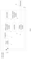
- the lamp dimming circuit with electricity leakage prevention function in the embodiment includes a power module 1, a PWM signal conversion module 2, an optocoupler 3, an analog signal conversion module 4, a controller 5, and a voltage conversion module 6 for connecting the illuminant.
- the PWM signal conversion module 2 has a signal input end for acquiring a dimming input signal; the PWM signal conversion module 2 is configured to acquire the dimming input signal and convert the dimming input signal into a PWM modulated signal; wherein, the PWM modulation signal is a pulse width modulation signal; the analog signal conversion module 4 is configured to convert the output signal of the optocoupler 3 into an analog signal; and the illuminant to which the voltage conversion module 6 is connected is preferably an LED lamp.
- a Y capacitor 7 is disposed between the power module 1 and the PWM signal conversion module 2, the power module 1 is connected to one end of the Y capacitor 7, and the other end of the Y capacitor 7 is connected to the PWM signal conversion module 2.
- the power module and the PWM signal conversion module 2 are span connected; the power module 1 supplies power to the PWM signal conversion module 2 through the Y capacitor 7; the signal output end of the PWM signal conversion module 2 is connected to the signal input end of the optocoupler 3.
- the signal output end of the optocoupler 3 is connected to the signal input end of the analog signal conversion module 4, and the signal output end of the analog signal conversion module 4 is connected to the controller 5.
- the controller 5 is connected to the voltage conversion module 6.
- the voltage conversion module 6 has a dimming signal output end for outputting a dimming signal to the illuminant.
- the controller 5 in this embodiment can use a microcontroller as needed; the power module 1 is connected to the power line (L, N) of the mains supply.
- the signal in the optocoupler 3 is transmitted in the form of an optical signal in which no signal in the form of current is present.
- the dimming input signal in the lamp dimming circuit is a 1 ⁇ 10V voltage signal.
- the duty ratio of the PWM signal converted by the PWM signal conversion module 2 in this embodiment is set to be 10% to 100%.
- the PWM signal conversion module 2 collects an external dimming input signal of 1-10V, and then converts the dimming input signal into PWM modulation signal with corresponding duty ratio.
- the PWM modulation signal is emitted through the signal input end of the optocoupler 3.
- the signal in the optocoupler 3 is not in the form of current, but is transmitted to the signal output end of the optocoupler 3 in the form of optical signal; the signal output end of the optocoupler 3 is PWM signal of shaping, the PWM signal after shaping is converted into a voltage signal in the form of an analog signal by the analog signal conversion module 4 and transmitted to the controller 5.
- the controller 5 correspondingly outputs another PWM signal to the voltage conversion module 6 by taking advantage of the functional relationship among the previous dimming input signal, the output signals of the PWM signal conversion module 2 and the analog signal conversion module 4. And the voltage conversion module 6 outputs a dimming output signal synchronized with the previous 1 ⁇ 10V dimming input signal.
- the first functional relationship is satisfied between the dimming input signal and the output signal of the PWM signal conversion module 2
- the second functional relationship is satisfied between the output signal of the PWM signal conversion module 2 and the output signal of the analog signal conversion module 4. Both the first functional relationship and the second functional relationship can be obtained by means of point fitting.
- the lamp dimming circuit is applied to dimming lamp, and the dimming lamp includes a illuminant 8 connected to the mains supply, and the dimming signal output end of the voltage conversion module 6 in the lamp dimming circuit is connected to the illuminant 8.
- the embodiment further provides a dimming lamp with electricity leakage preventing function, the dimming lamp includes an illuminant 8 connected to commercial power source and the lamp dimming circuit in the embodiment, and the dimming signal output of the voltage conversion module 6 in the lamp dimming circuit is connected to the illuminant 8.
- the illuminant 8 in this embodiment is an LED lamp.
Landscapes
- Circuit Arrangement For Electric Light Sources In General (AREA)
Claims (6)
- Lampendimmerschaltung mit Stromleckverhinderungsfunktion, die Folgendes umfasst:ein Leistungsmodul (1),ein PWM-Signalumwandlungsmodul (2),einen Optokoppler (3),ein Analogsignalumwandlungsmodul (4),einen Controller (5),ein Spannungswandlermodul (6) zum Anschluss eines Leuchtmittels (8) undeinen Y-Kondensator (7), wobeidas PWM-Signalumwandlungsmodul (2) ein Signaleingangsende zum Erfassen eines Dimm-Eingangssignals hat, wobei das Dimm-Eingangssignal ein 1~10V-Spannungssignal ist; der Y-Kondensator (7) zwischen dem Leistungsmodul (1) und dem PWM-Signalumwandlungsmodul (2) angeordnet ist, das Leistungsmodul (1) mit einem Ende des Y-Kondensators (7) verbunden ist, und das andere Ende des Y-Kondensators (7) mit dem PWM-Signalumwandlungsmodul (2) verbunden ist; das Signalausgangsende des PWM-Signalumwandlungsmoduls (2) ist mit dem Signaleingangsende des Optokopplers (3) verbunden, und das Signalausgangsende des Optokopplers (3) ist mit dem Signaleingangsende des Analogsignalumwandlungsmoduls (4) verbunden, und das Signalausgangsende des Analogsignalumwandlungsmoduls (4) ist mit dem Controller (5) verbunden; das Steuergerät (5) ist mit dem Spannungswandlermodul (6) verbunden und das Spannungswandlermodul (6) ist so konfiguriert, dass es ein Dimmausgangssignal ausgibt, das mit dem 1~10V Dimm-Eingangssignal synchronisiert ist; wobei:das PWM-Signalumwandlungsmodul (2) so konfiguriert ist, dass es das Dimm-Eingangssignal in ein PWM-moduliertes Signal umwandelt;das Analogsignalumwandlungsmodul (4) so konfiguriert ist, dass es ein Ausgangssignal des Optokopplers (3) in ein analoges Signal umwandelt.
- Lampendimmerschaltung nach Anspruch 1, wobei eine erste Funktionsbeziehung zwischen dem Dimm-Eingangssignal und dem Ausgangssignal des PWM-Signalumwandlungsmoduls erfüllt ist, und eine zweite Funktionsbeziehung zwischen dem Ausgangssignal des PWM-Signalumwandlungsmoduls und dem Ausgangssignal des Analogsignalumwandlungsmoduls erfüllt ist.
- Lampendimmerschaltung nach Anspruch 1, wobei das Leistungsmodul (1) an die Netzleitung (L, N) des Stromnetzes anschließbar ist.
- Lampendimmerschaltung nach einem der Ansprüche 1 bis 3, wobei das Leuchtmittel eine LED-Lampe ist.
- Lampendimmerschaltung nach einem der Ansprüche 1 bis 3, wobei der Controller (5) ein Mikrocontroller ist; oder/und in der Schaltung zum Dimmen von Lampen das Tastverhältnis des von dem PWM-Signalumwandlungsmodul (2) umgewandelten PWM-Signals im Bereich von 10 % bis 100 % liegt.
- Lampendimmerschaltung nach einem der Ansprüche 1 bis 5, wobei die Lampendimmerschaltung an eine Dimmlampe anschließbar ist und die Dimmlampe das an das Stromnetz angeschlossene Leuchtmittel (8) enthält.
Applications Claiming Priority (1)
| Application Number | Priority Date | Filing Date | Title |
|---|---|---|---|
| CN201810735756.9A CN108811251B (zh) | 2018-07-06 | 2018-07-06 | 具有预防漏电功能的灯具调光电路及调光灯具 |
Publications (2)
| Publication Number | Publication Date |
|---|---|
| EP3592115A1 EP3592115A1 (de) | 2020-01-08 |
| EP3592115B1 true EP3592115B1 (de) | 2023-03-08 |
Family
ID=64075329
Family Applications (1)
| Application Number | Title | Priority Date | Filing Date |
|---|---|---|---|
| EP19184767.2A Active EP3592115B1 (de) | 2018-07-06 | 2019-07-05 | Lampendimmerschaltung mit stromleckverhinderungsfunktion |
Country Status (3)
| Country | Link |
|---|---|
| US (1) | US10667364B2 (de) |
| EP (1) | EP3592115B1 (de) |
| CN (1) | CN108811251B (de) |
Family Cites Families (13)
| Publication number | Priority date | Publication date | Assignee | Title |
|---|---|---|---|---|
| JP5760176B2 (ja) * | 2011-03-23 | 2015-08-05 | パナソニックIpマネジメント株式会社 | 固体光源点灯装置およびそれを用いた照明器具と照明システム |
| JP5891454B2 (ja) * | 2011-04-18 | 2016-03-23 | パナソニックIpマネジメント株式会社 | 半導体発光素子の点灯装置およびそれを用いた照明器具 |
| US8975825B2 (en) * | 2012-05-08 | 2015-03-10 | Cree, Inc. | Light emitting diode driver with isolated control circuits |
| KR101334042B1 (ko) * | 2012-11-30 | 2013-11-28 | 주식회사 실리콘웍스 | Led 조명 장치 및 그의 전류 레귤레이터와 전류 레귤레이팅 방법 |
| CN203120261U (zh) * | 2013-03-29 | 2013-08-07 | 浙江盛开光电有限公司 | 一种led灯具智能调光控制系统 |
| ITTO20130579A1 (it) * | 2013-07-10 | 2015-01-11 | Osram Gmbh | Procedimento per la trasmissione di segnali e relativo dispositivo |
| CN204795738U (zh) * | 2015-06-29 | 2015-11-18 | 赛尔富电子有限公司 | 一种led灯具电源 |
| KR20170071229A (ko) * | 2015-12-15 | 2017-06-23 | 엘지이노텍 주식회사 | 조광기와 드라이버가 전기적 절연 구조를 가지는 조명 장치 및 시스템 |
| CN106793243B (zh) * | 2016-11-10 | 2019-04-30 | 深圳市朗科智能电气股份有限公司 | 0~10v led调光信号转换电路及led电源调光电路 |
| EP3399636B1 (de) * | 2017-05-04 | 2020-02-12 | OSRAM GmbH | Elektronischer umwandler und leuchtsystem |
| CN107426875A (zh) * | 2017-08-25 | 2017-12-01 | 赛尔富电子有限公司 | 一种恒压led灯具组的幅值调光电源 |
| CN107426874B (zh) * | 2017-08-25 | 2024-03-15 | 赛尔富电子有限公司 | 一种用于led灯的调光控制电源 |
| CN208572496U (zh) * | 2018-07-06 | 2019-03-01 | 赛尔富电子有限公司 | 具有预防漏电功能的灯具调光电路及调光灯具 |
-
2018
- 2018-07-06 CN CN201810735756.9A patent/CN108811251B/zh active Active
-
2019
- 2019-07-02 US US16/460,175 patent/US10667364B2/en active Active
- 2019-07-05 EP EP19184767.2A patent/EP3592115B1/de active Active
Also Published As
| Publication number | Publication date |
|---|---|
| CN108811251A (zh) | 2018-11-13 |
| US10667364B2 (en) | 2020-05-26 |
| US20200015337A1 (en) | 2020-01-09 |
| EP3592115A1 (de) | 2020-01-08 |
| CN108811251B (zh) | 2023-10-13 |
Similar Documents
| Publication | Publication Date | Title |
|---|---|---|
| CN103139992B (zh) | 带可控硅旁路调光电路的led调光驱动系统 | |
| CN101861018B (zh) | 可调光的led开关电源 | |
| CN107426874B (zh) | 一种用于led灯的调光控制电源 | |
| CN101835317A (zh) | 一种具有智能调光功能的反激式路灯照明led恒流驱动电源 | |
| CN201690655U (zh) | 一种具有智能调光功能的反激式路灯照明led恒流驱动电源 | |
| CN215222534U (zh) | 一种调光驱动电路、调光驱动装置及灯具 | |
| CN103139990A (zh) | 一种可调光led驱动电源 | |
| CN203193980U (zh) | 多通道可调光的led灯管驱动电路 | |
| CN216873427U (zh) | 一种兼容多种调光器的驱动电路 | |
| CN101539251B (zh) | 高功率因数led照明系统 | |
| CN204598359U (zh) | 一种用于可见光通信的多灯具联网驱动电路 | |
| CN201995174U (zh) | 一种后沿小相角调光电路 | |
| JP6373947B2 (ja) | 調光器及びドライバが電気的絶縁構造を有する照明装置及びシステム | |
| CN203896539U (zh) | 用于led照明的无需调光器的调光恒流驱动电源 | |
| US10667364B2 (en) | Lamp dimming circuit with electricity leakage preventing function | |
| US9942959B1 (en) | Phase-cut dimmable power supply with wide input voltage | |
| CN219938566U (zh) | 一种同时兼容两种调光的led驱动电路 | |
| CN204795738U (zh) | 一种led灯具电源 | |
| CN201319684Y (zh) | 发光负载的电源驱动及调光装置 | |
| CN203814005U (zh) | 具有开启触发锁定记忆功能的led调光电路 | |
| CN203243554U (zh) | 一种led日光灯恒流源多路均流电路 | |
| CN218243889U (zh) | 一种led灯调色调光控制系统、控制器及照明装置 | |
| CN204859684U (zh) | 一种led恒流调光系统 | |
| CN203827584U (zh) | 一种串联数字信号传输智能控制系统 | |
| CN218550240U (zh) | 一种led灯调光控制系统及可调光植栽led补光灯 |
Legal Events
| Date | Code | Title | Description |
|---|---|---|---|
| PUAI | Public reference made under article 153(3) epc to a published international application that has entered the european phase |
Free format text: ORIGINAL CODE: 0009012 |
|
| STAA | Information on the status of an ep patent application or granted ep patent |
Free format text: STATUS: THE APPLICATION HAS BEEN PUBLISHED |
|
| AK | Designated contracting states |
Kind code of ref document: A1 Designated state(s): AL AT BE BG CH CY CZ DE DK EE ES FI FR GB GR HR HU IE IS IT LI LT LU LV MC MK MT NL NO PL PT RO RS SE SI SK SM TR |
|
| AX | Request for extension of the european patent |
Extension state: BA ME |
|
| STAA | Information on the status of an ep patent application or granted ep patent |
Free format text: STATUS: REQUEST FOR EXAMINATION WAS MADE |
|
| 17P | Request for examination filed |
Effective date: 20201009 |
|
| RBV | Designated contracting states (corrected) |
Designated state(s): AL AT BE BG CH CY CZ DE DK EE ES FI FR GB GR HR HU IE IS IT LI LT LU LV MC MK MT NL NO PL PT RO RS SE SI SK SM TR |
|
| REG | Reference to a national code |
Ref country code: DE Ref legal event code: R079 Ref document number: 602019026067 Country of ref document: DE Free format text: PREVIOUS MAIN CLASS: H05B0033080000 Ipc: H05B0045100000 |
|
| RIC1 | Information provided on ipc code assigned before grant |
Ipc: H05B 45/50 20200101ALI20220621BHEP Ipc: H05B 45/10 20200101AFI20220621BHEP |
|
| GRAP | Despatch of communication of intention to grant a patent |
Free format text: ORIGINAL CODE: EPIDOSNIGR1 |
|
| STAA | Information on the status of an ep patent application or granted ep patent |
Free format text: STATUS: GRANT OF PATENT IS INTENDED |
|
| INTG | Intention to grant announced |
Effective date: 20220928 |
|
| RIN1 | Information on inventor provided before grant (corrected) |
Inventor name: YING, JUNJUN Inventor name: FANG, JUNQI |
|
| GRAS | Grant fee paid |
Free format text: ORIGINAL CODE: EPIDOSNIGR3 |
|
| GRAA | (expected) grant |
Free format text: ORIGINAL CODE: 0009210 |
|
| STAA | Information on the status of an ep patent application or granted ep patent |
Free format text: STATUS: THE PATENT HAS BEEN GRANTED |
|
| AK | Designated contracting states |
Kind code of ref document: B1 Designated state(s): AL AT BE BG CH CY CZ DE DK EE ES FI FR GB GR HR HU IE IS IT LI LT LU LV MC MK MT NL NO PL PT RO RS SE SI SK SM TR |
|
| REG | Reference to a national code |
Ref country code: CH Ref legal event code: EP Ref country code: AT Ref legal event code: REF Ref document number: 1553439 Country of ref document: AT Kind code of ref document: T Effective date: 20230315 |
|
| REG | Reference to a national code |
Ref country code: DE Ref legal event code: R096 Ref document number: 602019026067 Country of ref document: DE |
|
| REG | Reference to a national code |
Ref country code: IE Ref legal event code: FG4D |
|
| REG | Reference to a national code |
Ref country code: LT Ref legal event code: MG9D |
|
| REG | Reference to a national code |
Ref country code: NL Ref legal event code: MP Effective date: 20230308 |
|
| PG25 | Lapsed in a contracting state [announced via postgrant information from national office to epo] |
Ref country code: RS Free format text: LAPSE BECAUSE OF FAILURE TO SUBMIT A TRANSLATION OF THE DESCRIPTION OR TO PAY THE FEE WITHIN THE PRESCRIBED TIME-LIMIT Effective date: 20230308 Ref country code: NO Free format text: LAPSE BECAUSE OF FAILURE TO SUBMIT A TRANSLATION OF THE DESCRIPTION OR TO PAY THE FEE WITHIN THE PRESCRIBED TIME-LIMIT Effective date: 20230608 Ref country code: LV Free format text: LAPSE BECAUSE OF FAILURE TO SUBMIT A TRANSLATION OF THE DESCRIPTION OR TO PAY THE FEE WITHIN THE PRESCRIBED TIME-LIMIT Effective date: 20230308 Ref country code: LT Free format text: LAPSE BECAUSE OF FAILURE TO SUBMIT A TRANSLATION OF THE DESCRIPTION OR TO PAY THE FEE WITHIN THE PRESCRIBED TIME-LIMIT Effective date: 20230308 Ref country code: HR Free format text: LAPSE BECAUSE OF FAILURE TO SUBMIT A TRANSLATION OF THE DESCRIPTION OR TO PAY THE FEE WITHIN THE PRESCRIBED TIME-LIMIT Effective date: 20230308 Ref country code: ES Free format text: LAPSE BECAUSE OF FAILURE TO SUBMIT A TRANSLATION OF THE DESCRIPTION OR TO PAY THE FEE WITHIN THE PRESCRIBED TIME-LIMIT Effective date: 20230308 |
|
| REG | Reference to a national code |
Ref country code: AT Ref legal event code: MK05 Ref document number: 1553439 Country of ref document: AT Kind code of ref document: T Effective date: 20230308 |
|
| PG25 | Lapsed in a contracting state [announced via postgrant information from national office to epo] |
Ref country code: SE Free format text: LAPSE BECAUSE OF FAILURE TO SUBMIT A TRANSLATION OF THE DESCRIPTION OR TO PAY THE FEE WITHIN THE PRESCRIBED TIME-LIMIT Effective date: 20230308 Ref country code: NL Free format text: LAPSE BECAUSE OF FAILURE TO SUBMIT A TRANSLATION OF THE DESCRIPTION OR TO PAY THE FEE WITHIN THE PRESCRIBED TIME-LIMIT Effective date: 20230308 Ref country code: GR Free format text: LAPSE BECAUSE OF FAILURE TO SUBMIT A TRANSLATION OF THE DESCRIPTION OR TO PAY THE FEE WITHIN THE PRESCRIBED TIME-LIMIT Effective date: 20230609 Ref country code: FI Free format text: LAPSE BECAUSE OF FAILURE TO SUBMIT A TRANSLATION OF THE DESCRIPTION OR TO PAY THE FEE WITHIN THE PRESCRIBED TIME-LIMIT Effective date: 20230308 |
|
| PG25 | Lapsed in a contracting state [announced via postgrant information from national office to epo] |
Ref country code: SM Free format text: LAPSE BECAUSE OF FAILURE TO SUBMIT A TRANSLATION OF THE DESCRIPTION OR TO PAY THE FEE WITHIN THE PRESCRIBED TIME-LIMIT Effective date: 20230308 Ref country code: RO Free format text: LAPSE BECAUSE OF FAILURE TO SUBMIT A TRANSLATION OF THE DESCRIPTION OR TO PAY THE FEE WITHIN THE PRESCRIBED TIME-LIMIT Effective date: 20230308 Ref country code: PT Free format text: LAPSE BECAUSE OF FAILURE TO SUBMIT A TRANSLATION OF THE DESCRIPTION OR TO PAY THE FEE WITHIN THE PRESCRIBED TIME-LIMIT Effective date: 20230710 Ref country code: EE Free format text: LAPSE BECAUSE OF FAILURE TO SUBMIT A TRANSLATION OF THE DESCRIPTION OR TO PAY THE FEE WITHIN THE PRESCRIBED TIME-LIMIT Effective date: 20230308 Ref country code: CZ Free format text: LAPSE BECAUSE OF FAILURE TO SUBMIT A TRANSLATION OF THE DESCRIPTION OR TO PAY THE FEE WITHIN THE PRESCRIBED TIME-LIMIT Effective date: 20230308 Ref country code: AT Free format text: LAPSE BECAUSE OF FAILURE TO SUBMIT A TRANSLATION OF THE DESCRIPTION OR TO PAY THE FEE WITHIN THE PRESCRIBED TIME-LIMIT Effective date: 20230308 |
|
| PG25 | Lapsed in a contracting state [announced via postgrant information from national office to epo] |
Ref country code: SK Free format text: LAPSE BECAUSE OF FAILURE TO SUBMIT A TRANSLATION OF THE DESCRIPTION OR TO PAY THE FEE WITHIN THE PRESCRIBED TIME-LIMIT Effective date: 20230308 Ref country code: PL Free format text: LAPSE BECAUSE OF FAILURE TO SUBMIT A TRANSLATION OF THE DESCRIPTION OR TO PAY THE FEE WITHIN THE PRESCRIBED TIME-LIMIT Effective date: 20230308 Ref country code: IS Free format text: LAPSE BECAUSE OF FAILURE TO SUBMIT A TRANSLATION OF THE DESCRIPTION OR TO PAY THE FEE WITHIN THE PRESCRIBED TIME-LIMIT Effective date: 20230708 |
|
| REG | Reference to a national code |
Ref country code: DE Ref legal event code: R097 Ref document number: 602019026067 Country of ref document: DE |
|
| PLBE | No opposition filed within time limit |
Free format text: ORIGINAL CODE: 0009261 |
|
| STAA | Information on the status of an ep patent application or granted ep patent |
Free format text: STATUS: NO OPPOSITION FILED WITHIN TIME LIMIT |
|
| PG25 | Lapsed in a contracting state [announced via postgrant information from national office to epo] |
Ref country code: SI Free format text: LAPSE BECAUSE OF FAILURE TO SUBMIT A TRANSLATION OF THE DESCRIPTION OR TO PAY THE FEE WITHIN THE PRESCRIBED TIME-LIMIT Effective date: 20230308 Ref country code: DK Free format text: LAPSE BECAUSE OF FAILURE TO SUBMIT A TRANSLATION OF THE DESCRIPTION OR TO PAY THE FEE WITHIN THE PRESCRIBED TIME-LIMIT Effective date: 20230308 |
|
| 26N | No opposition filed |
Effective date: 20231211 |
|
| PG25 | Lapsed in a contracting state [announced via postgrant information from national office to epo] |
Ref country code: MC Free format text: LAPSE BECAUSE OF FAILURE TO SUBMIT A TRANSLATION OF THE DESCRIPTION OR TO PAY THE FEE WITHIN THE PRESCRIBED TIME-LIMIT Effective date: 20230308 |
|
| PG25 | Lapsed in a contracting state [announced via postgrant information from national office to epo] |
Ref country code: MC Free format text: LAPSE BECAUSE OF FAILURE TO SUBMIT A TRANSLATION OF THE DESCRIPTION OR TO PAY THE FEE WITHIN THE PRESCRIBED TIME-LIMIT Effective date: 20230308 |
|
| REG | Reference to a national code |
Ref country code: CH Ref legal event code: PL |
|
| REG | Reference to a national code |
Ref country code: BE Ref legal event code: MM Effective date: 20230731 |
|
| PG25 | Lapsed in a contracting state [announced via postgrant information from national office to epo] |
Ref country code: LU Free format text: LAPSE BECAUSE OF NON-PAYMENT OF DUE FEES Effective date: 20230705 |
|
| GBPC | Gb: european patent ceased through non-payment of renewal fee |
Effective date: 20230705 |
|
| PG25 | Lapsed in a contracting state [announced via postgrant information from national office to epo] |
Ref country code: LU Free format text: LAPSE BECAUSE OF NON-PAYMENT OF DUE FEES Effective date: 20230705 |
|
| REG | Reference to a national code |
Ref country code: IE Ref legal event code: MM4A |
|
| PG25 | Lapsed in a contracting state [announced via postgrant information from national office to epo] |
Ref country code: CH Free format text: LAPSE BECAUSE OF NON-PAYMENT OF DUE FEES Effective date: 20230731 Ref country code: GB Free format text: LAPSE BECAUSE OF NON-PAYMENT OF DUE FEES Effective date: 20230705 |
|
| PG25 | Lapsed in a contracting state [announced via postgrant information from national office to epo] |
Ref country code: IT Free format text: LAPSE BECAUSE OF FAILURE TO SUBMIT A TRANSLATION OF THE DESCRIPTION OR TO PAY THE FEE WITHIN THE PRESCRIBED TIME-LIMIT Effective date: 20230308 Ref country code: FR Free format text: LAPSE BECAUSE OF NON-PAYMENT OF DUE FEES Effective date: 20230731 Ref country code: BE Free format text: LAPSE BECAUSE OF NON-PAYMENT OF DUE FEES Effective date: 20230731 |
|
| PG25 | Lapsed in a contracting state [announced via postgrant information from national office to epo] |
Ref country code: IE Free format text: LAPSE BECAUSE OF NON-PAYMENT OF DUE FEES Effective date: 20230705 |
|
| PG25 | Lapsed in a contracting state [announced via postgrant information from national office to epo] |
Ref country code: IE Free format text: LAPSE BECAUSE OF NON-PAYMENT OF DUE FEES Effective date: 20230705 |
|
| PG25 | Lapsed in a contracting state [announced via postgrant information from national office to epo] |
Ref country code: BG Free format text: LAPSE BECAUSE OF FAILURE TO SUBMIT A TRANSLATION OF THE DESCRIPTION OR TO PAY THE FEE WITHIN THE PRESCRIBED TIME-LIMIT Effective date: 20230308 |
|
| PG25 | Lapsed in a contracting state [announced via postgrant information from national office to epo] |
Ref country code: BG Free format text: LAPSE BECAUSE OF FAILURE TO SUBMIT A TRANSLATION OF THE DESCRIPTION OR TO PAY THE FEE WITHIN THE PRESCRIBED TIME-LIMIT Effective date: 20230308 |
|
| PG25 | Lapsed in a contracting state [announced via postgrant information from national office to epo] |
Ref country code: CY Free format text: LAPSE BECAUSE OF FAILURE TO SUBMIT A TRANSLATION OF THE DESCRIPTION OR TO PAY THE FEE WITHIN THE PRESCRIBED TIME-LIMIT; INVALID AB INITIO Effective date: 20190705 |
|
| PG25 | Lapsed in a contracting state [announced via postgrant information from national office to epo] |
Ref country code: HU Free format text: LAPSE BECAUSE OF FAILURE TO SUBMIT A TRANSLATION OF THE DESCRIPTION OR TO PAY THE FEE WITHIN THE PRESCRIBED TIME-LIMIT; INVALID AB INITIO Effective date: 20190705 |
|
| PGFP | Annual fee paid to national office [announced via postgrant information from national office to epo] |
Ref country code: DE Payment date: 20250731 Year of fee payment: 7 |
|
| PG25 | Lapsed in a contracting state [announced via postgrant information from national office to epo] |
Ref country code: TR Free format text: LAPSE BECAUSE OF FAILURE TO SUBMIT A TRANSLATION OF THE DESCRIPTION OR TO PAY THE FEE WITHIN THE PRESCRIBED TIME-LIMIT Effective date: 20230308 |