EP3591799B1 - Avr-bypass-relaisschweissdetektion - Google Patents
Avr-bypass-relaisschweissdetektion Download PDFInfo
- Publication number
- EP3591799B1 EP3591799B1 EP19181964.8A EP19181964A EP3591799B1 EP 3591799 B1 EP3591799 B1 EP 3591799B1 EP 19181964 A EP19181964 A EP 19181964A EP 3591799 B1 EP3591799 B1 EP 3591799B1
- Authority
- EP
- European Patent Office
- Prior art keywords
- output
- relay
- input
- primary winding
- power
- Prior art date
- Legal status (The legal status is an assumption and is not a legal conclusion. Google has not performed a legal analysis and makes no representation as to the accuracy of the status listed.)
- Active
Links
Images



Classifications
-
- H—ELECTRICITY
- H02—GENERATION; CONVERSION OR DISTRIBUTION OF ELECTRIC POWER
- H02J—ELECTRIC POWER NETWORKS; CIRCUIT ARRANGEMENTS OR SYSTEMS FOR SUPPLYING OR DISTRIBUTING ELECTRIC POWER; SYSTEMS FOR STORING ELECTRIC ENERGY
- H02J9/00—Circuit arrangements for emergency or stand-by power supply, e.g. for emergency lighting
- H02J9/04—Circuit arrangements for emergency or stand-by power supply, e.g. for emergency lighting in which the distribution system is disconnected from the normal source and connected to a standby source
- H02J9/06—Circuit arrangements for emergency or stand-by power supply, e.g. for emergency lighting in which the distribution system is disconnected from the normal source and connected to a standby source with automatic change-over, e.g. UPS systems
- H02J9/062—Circuit arrangements for emergency or stand-by power supply, e.g. for emergency lighting in which the distribution system is disconnected from the normal source and connected to a standby source with automatic change-over, e.g. UPS systems for AC powered loads
-
- H—ELECTRICITY
- H01—ELECTRIC ELEMENTS
- H01H—ELECTRIC SWITCHES; RELAYS; SELECTORS; EMERGENCY PROTECTIVE DEVICES
- H01H47/00—Circuit arrangements not adapted to a particular application of the relay and designed to obtain desired operating characteristics or to provide energising current
- H01H47/002—Monitoring or fail-safe circuits
-
- H—ELECTRICITY
- H01—ELECTRIC ELEMENTS
- H01H—ELECTRIC SWITCHES; RELAYS; SELECTORS; EMERGENCY PROTECTIVE DEVICES
- H01H47/00—Circuit arrangements not adapted to a particular application of the relay and designed to obtain desired operating characteristics or to provide energising current
- H01H47/002—Monitoring or fail-safe circuits
- H01H2047/003—Detecting welded contacts and applying weld break pulses to coil
-
- H—ELECTRICITY
- H02—GENERATION; CONVERSION OR DISTRIBUTION OF ELECTRIC POWER
- H02J—ELECTRIC POWER NETWORKS; CIRCUIT ARRANGEMENTS OR SYSTEMS FOR SUPPLYING OR DISTRIBUTING ELECTRIC POWER; SYSTEMS FOR STORING ELECTRIC ENERGY
- H02J9/00—Circuit arrangements for emergency or stand-by power supply, e.g. for emergency lighting
- H02J9/04—Circuit arrangements for emergency or stand-by power supply, e.g. for emergency lighting in which the distribution system is disconnected from the normal source and connected to a standby source
- H02J9/06—Circuit arrangements for emergency or stand-by power supply, e.g. for emergency lighting in which the distribution system is disconnected from the normal source and connected to a standby source with automatic change-over, e.g. UPS systems
- H02J9/068—Electronic means for switching from one power supply to another power supply, e.g. to avoid parallel connection
Definitions
- the present invention relates generally to systems and methods for controlling an Uninterruptible Power Supply (UPS).
- UPS Uninterruptible Power Supply
- UPS uninterruptible power supplies
- Known uninterruptible power supplies include on-line UPS's, off-line UPS's, line-interactive UPS's as well as others.
- On-line UPS's provide conditioned AC power as well as back-up AC power upon interruption of a primary source of AC power.
- Off-line UPS's typically do not provide conditioning of input AC power, but do provide back-up AC power upon interruption of the primary AC power source.
- Line-interactive UPS's are similar to off-line UPS's in that they switch to battery power when a blackout occurs but also typically include a multi-tap Automatic Voltage Regulation (AVR) transformer for regulating the output voltage provided by the UPS when a power line sag or swell occurs without draining the battery.
- AVR Automatic Voltage Regulation
- an Uninterruptible Power Supply (UPS) system comprising an input to receive input AC power, an output to provide AC output power to a load, a neutral connection, an automatic voltage regulation (AVR) transformer having a primary winding and a secondary winding, a plurality of relays coupled to the input, the output, and the primary winding, the plurality of relays configured to selectively couple the primary winding to the input and the output, a bypass relay configured to selectively couple the primary winding of the AVR transformer to the neutral connection, a DC/AC inverter circuit coupled to the secondary winding and configured to be coupled to a backup power source and to receive backup DC power from the backup power source, and a controller configured to operate the plurality of relays, the bypass relay, and the DC/AC inverter circuit to provide the output AC power to the load derived from at least one of the input AC power and the backup DC power, wherein in a backup power mode of operation, the controller is further configured to operate the plurality of relays to
- the UPS further comprises a user interface, wherein in response to identifying that the bypass relay has decoupled the primary winding from the neutral connection, the controller is further configured to transmit a notification to the user interface indicating that the bypass relay has decoupled the primary winding from the neutral connection.
- the controller includes an interface configured to communicate with at least one external system, and wherein in response to identifying that the bypass relay has decoupled the primary winding from the neutral connection, the controller is further configured to transmit a notification to the at least one external system that the bypass relay has decoupled the primary winding from the neutral connection.
- the controller in monitoring the AC output power the controller is further configured to monitor an output voltage level and an output current level at the output. In one embodiment, the controller is further configured to compare the monitored output voltage level to an output voltage threshold. In another embodiment, in response to determining that the output voltage level is less than the output voltage threshold, the controller is further configured to compare the output current level to an output current threshold. In one embodiment, in response to determining that the output current level is less than the output current threshold, the controller is further configured to identify that the bypass relay has decoupled the primary winding from the neutral connection. In another embodiment, in response to determining that the output current level is greater than the output current threshold, the controller is further configured to identify that the load coupled to the output is short circuited.
- the AVR transformer further comprises a first tap coupled to a first location of the primary winding and a second tap coupled to a second location of the primary winding
- the plurality of relays comprises a line transfer relay configured to selectively couple the AVR transformer to the input, a boost relay configured to selectively couple the first tap to the line transfer relay, and a trim relay configured to selectively couple the second tap to the output.
- the controller in the backup power mode of operation, is further configured to operate the line transfer relay to decouple the AVR transformer from the input, and to operate the trim relay to couple the second tap to the output.
- the controller in a boost mode of operation, is further configured to operate the line transfer relay to couple the AVR transformer to the input, to operate the boost relay to couple the line transfer relay to the first tap, to operate the trim relay to couple the primary winding to the output, and to operate the bypass relay to couple the primary winding to the neutral connection, and wherein in the boost mode of operation, a voltage level at the output is greater than a voltage level at the input.
- the controller in the boost mode of operation, is further configured to operate the trim relay to couple the second tap to the output.
- the controller in a trim mode of operation, is further configured to operate the line transfer relay to couple the AVR transformer to the input, to operate the boost relay to decouple the first tap from the line transfer relay, to operate the trim relay to couple the second tap to the output, and to operate the bypass relay to couple the primary winding to the neutral connection, and wherein in the trim mode of operation, a voltage level at the output is less than a voltage level at the input.
- Another aspect in accord with the present invention is directed to a method of identifying a welded relay condition in a line-interactive UPS comprising an input to receive input AC power, an output to provide AC output power to a load, a neutral connection, an automatic voltage regulation (AVR) transformer having a primary winding and a secondary winding, a plurality of relays coupled to the input, the output, and the primary winding, the plurality of relays configured to selectively couple the primary winding to the input and the output, a bypass relay configured to selectively couple the primary winding of the AVR transformer to the neutral connection, and a DC/AC inverter circuit coupled to the secondary winding and configured to be coupled to a backup power source and to receive backup DC power from the backup power source, wherein the method comprises acts of operating, in a backup power mode of operation, the plurality of relays, the bypass relay, and the DC/AC inverter circuit to provide the AC output power to the load derived from the backup DC power, monitoring the AC output power, and determining, based on the
- monitoring the AC output power comprises monitoring an output voltage level at the output, and monitoring an output current level at the output.
- determining whether the line-interactive UPS is in the welded relay condition comprises comparing the output voltage level to an output voltage threshold, in response to determining that the output voltage level is less than the output voltage threshold, comparing the output current level to an output current threshold, and in response to determining that the output current level is less than the output current threshold, determining that the line-interactive UPS is in the welded relay condition. In one embodiment, in response to determining that the output current level is greater than the output current threshold, determining that the line-interactive UPS is in a short circuit condition.
- the method further comprises operating, in a boost mode of operation, the plurality of relays and the bypass relay to generate a voltage level at the output which is greater than a voltage level at the input. In one embodiment, the method further comprises operating, in a trim mode of operation, the plurality of relays and the bypass relay to generate a voltage level at the output which is less than a voltage level at the input.
- At least one aspect in accord with the present invention is directed to an Uninterruptible Power Supply (UPS) system comprising an input to receive input AC power, an output to provide AC output power to a load, a neutral connection, an automatic voltage regulation (AVR) transformer having a primary winding and a secondary winding, a plurality of relays coupled to the input, the output, and the primary winding, the plurality of relays configured to selectively couple the primary winding to the input and the output, a bypass relay configured to selectively couple the primary winding of the AVR transformer to the neutral connection, a DC/AC inverter circuit coupled to the secondary winding and configured to be coupled to a backup power source and to receive backup DC power from the backup power source, and means for operating the UPS system to provide the output AC power to the load derived from at least one of the input AC power and the backup DC power and for identifying that the bypass relay is in a position decoupling the primary winding from the neutral connection when the UPS system is operated to provide the output AC power derived from the backup DC power.
- references to "or” may be construed as inclusive so that any terms described using “or” may indicate any of a single, more than one, and all of the described terms.
- the term usage in the incorporated references is supplementary to that of this document; for irreconcilable inconsistencies, the term usage in this document controls.
- a conventional line-interactive UPS includes an Automatic Voltage Regulation (AVR) transformer for regulating the output voltage provided by the UPS when a power line sag or swell condition occurs.
- AVR Automatic Voltage Regulation
- the output voltage of a conventional line-interactive UPS is typically monitored to confirm that the desired output voltage is being provided by the line-interactive UPS and that a fault condition does not exist. For example, a determination that the output voltage of a conventional line-interactive UPS is abnormally low (e.g., below a threshold level) may lead to a conclusion by an operator of the UPS that a short circuit condition exists at the output of the line-interactive UPS (e.g., because of a shorted load). However, the abnormally low output voltage of the line-interactive UPS may actually be an indication that a different type of error condition exists in the line-interactive UPS.
- a line-interactive UPS includes a bypass relay that is configured to de-energize the AVR transformer when operation of the transformer is not desired (e.g., to prevent losses)
- contacts of the bypass relay can become welded together and the bypass relay can become stuck in an open state where the transformer remains de-energized even though the line-interactive UPS is attempting to regulate output voltage with the transformer.
- the voltage at the output of the line-interactive UPS may also be abnormally low (e.g., at a level close to zero which is similar to the level that occurs in the short circuit condition described above).
- a system and method is provided for accurately identifying a welded relay condition in a line-interactive UPS.
- FIG. 1 is a block diagram of a line-interactive UPS 100.
- the line-interactive UPS 100 includes an input 101, a filter 102, a line transfer relay 104, a neutral transfer relay 106, a boost relay 108, a trim relay 110, an AVR transformer 112, an AVR bypass relay 114, a DC/AC inverter circuit 116, an output relay 118, an output 120, a neutral line 121, and a controller 122.
- the AVR transformer 112 includes a primary winding 111, a secondary winding 113, a first tap 115 coupled to a first location of the primary winding 111, and a second tap 117 coupled to a second location of the primary winding 111.
- the input 101 is configured to be coupled to an AC power source 123.
- the filter 102 is coupled to the input 101.
- the line transfer relay 104 and the neutral transfer relay 106 are coupled to the filter 102.
- the boost relay 108 is coupled to the line transfer relay 104 and selectively coupled to either a first end of the primary winding 111 or the first tap 115.
- the trim relay 110 is coupled to the output relay 118 and is selectively coupled to either the first end of the primary winding 111 or the second tap 117.
- the output 120 is coupled to the output relay 118 and is also configured to be coupled to a load 124.
- the neutral transfer relay 106 is configured to be coupled to the load 124 via the neutral line 121.
- the AVR bypass relay 114 is coupled between the neutral line 121 and a second end of the primary winding 111.
- the secondary winding 113 is coupled to the DC/AC inverter circuit 116.
- the DC/AC inverter circuit 116 is configured to be coupled to a backup power source 126 (e.g., a battery).
- the DC/AC inverter circuit 116 is a bidirectional inverter (i.e., can operate as both a DC/AC inverter and an AC/DC converter).
- the controller 122 is configured to control the operational state of the line transfer relay 104, the neutral transfer relay 106, the boost relay 108, the trim relay 110, and the AVR bypass relay 114 by transmitting control signals to each relay.
- the controller 122 is also configured to control operation of the DC/AC inverter circuit 116 by transmitting control signals to the inverter circuit 116.
- the controller 122 is coupled to a current sensor 128 (coupled between the trim relay 110 and the output relay 118) that is configured to output a measurement signal having a level corresponding to the level of current provided to the output 120 via the output relay 118.
- the controller 122 is coupled to a voltage sensor 129 (coupled to the output 120) that is configured to output a measurement signal having a level corresponding to a voltage level at the output 120.
- the controller 122 includes a single controller; however, in other embodiments, the controller 122 is a distributed system including more than one controller. The controller 122 can monitor and control the UPS 100 based on the measurement signal received from the current sensor 128, the voltage sensor 129, and/or additional measurement signals received from other sensors in the UPS 100.
- the controller 122 monitors the status of the UPS 100 by reading the output of a voltage sense circuit coupled to the input 101. In monitoring this sensor output, the controller 122 determines whether the input voltage provided to the UPS 100 by the power source 123 is in a normal or abnormal condition. The input voltage at the input 101 is in an abnormal condition if the input voltage is in a blackout, sag, or swell condition. Irrespective of the condition of the input voltage, the controller 122 operates the UPS 100 so that the voltage level at the output 120 is within a predetermined range, i.e. a nominal value plus or minus a given threshold.
- the controller 122 operates, in a pass through mode of operation, the line transfer relay 104 to couple the filter 102 to the boost relay 108, the boost relay to couple the line transfer relay 104 to the trim relay 110, the trim relay 110 to couple the boost relay 108 to the output relay 118, the output relay to couple the trim relay 110 to the output 120, the neutral transfer relay 106 to couple the filter 102 to the neutral line 121.
- the first tap 115 and the second tap 117 are de-energized and the voltage level at the output 120 is maintained at a level equal to the voltage level at the input 101 without requiring regulation by the AVR transformer 112.
- the controller 122 operates the AVR bypass relay 114 to decouple the primary winding 111 of the AVR transformer 112 from the neutral line 121 such that the primary winding 111 is de-energized
- the controller 122 operates the line transfer relay 104 to couple the filter 102 to the boost relay 108, the output relay to couple the trim relay 110 to the output 120, and the neutral transfer relay 106 to couple the filter 102 to the neutral line 121.
- the controller 122 also operates the boost relay 108 and the trim relay 110 to energize the first tap 115 and/or the second tap 117 such that the AVR transformer 112 generates a regulated output voltage at the output 120.
- the controller 122 adjusts the boost relay 108 and the trim relay 110 to a boost mode of operation.
- the boost relay 108 is operated to couple the line transfer relay 104 to the first tap 115 so that the first tap 115 is energized
- the trim relay 110 is operated to couple the second tap 117 to the output relay 118 so that the second tap 117 is energized.
- the boost relay 108 Upon the first tap 115 and second taps 117 being energized, current passes from the boost relay 108 to the trim relay 100 via the first tap 115, a portion of the primary winding 111, and the second tap 117, resulting in the voltage level at the output 120 being greater than the voltage level at the input 101.
- the increase in voltage between the output 120 and input 101 due to the AVR transformer 112 correlates to the turn ratio of the AVR transformer 112 which varies depending on where the primary winding 111 is tapped (determined by the boost relay 108, the trim relay 110, and corresponding taps 115, 117).
- the voltage level at the output 120 may be increased, in relation to the voltage level at the input 101, by a first ratio that is 1:1.15. In other embodiments, the first ratio may be configured differently.
- the controller 122 can operate the trim relay 110 to couple the first end of the primary winding 111 to the output relay 118, so that that second tap 117 is de-energized and current passes from the boost relay 108 to the output relay 118 via the first tap 115, a second portion of the primary winding 111 (wherein the second portion of the primary winding is larger than the first portion), the first end of the primary winding 111, and the trim relay 110.
- the turn ratio of the AVR transformer 112 is effectively increased, resulting in a larger voltage at the output 120.
- the voltage level at the output 120 may be increased by a second ratio which is greater than the first ratio.
- the second ratio may be double the value of the first ratio (e.g., 1:1.3).
- the second ratio may be configured differently.
- the controller 122 adjusts the boost relay 108 and the trim relay 110 to a trim mode of operation.
- the boost relay 108 is operated to couple the line transfer relay 104 to the first end of the primary winding 111 so that the first tap 115 is de-energized
- the trim relay 110 is operated to couple the second tap 117 to the output relay 118 so that the second tap 117 is energized.
- the boost relay 110 Upon the second tap being energized, current passes (in an opposite direction to that of the boost mode) from the boost relay to the trim relay 110 via the first end of the primary winding 111, a portion of the primary winding 111, and the second tap 117, resulting in the voltage level at the output 120 being less than the voltage level at the input 101.
- the decrease of voltage between the output 120 and input 101 due to the AVR transformer122 is directly correlated to the turn ratio of the AVR transformer 12.
- the voltage at the output 120 may be decreased, in relation to the voltage at the input 101, by a ratio of 1.15:1. In other embodiments, the ratio in the trim mode can be configured differently.
- the controller 122 operates the AVR bypass relay 114 to couple the primary winding 111 to the neutral line to energize the primary winding 111.
- voltage across the primary winding 111 generates a voltage across the secondary winding 113
- the controller 122 operates the bidirectional DC/AC inverter circuit to convert the voltage across the secondary winding 113 into a DC voltage to charge the backup power source 126 (e.g., battery).
- the controller 122 activates the line transfer relay 104 and the neutral transfer relay 106 to de-couple the AVR transformer 112 from the input 101, and operates the boost relay 108 and the trim relay 110 in a backup power mode of operation.
- the controller 122 operates the boost relay 108 to couple the line transfer relay 104 to the first end of the primary winding 111, and the trim relay to couple the second tap 117 to the output relay 118 to energize the second tap 117.
- DC power from the backup power source 126 is provided to the DC/AC inverter 116 and the controller 122 operates the DC/AC inverter 116 to convert the received DC power into converted AC power.
- the converted AC power from the DC/AC inverter 116 is provided to the secondary winding 113, which generates a corresponding voltage across the primary winding 111.
- the voltage across the primary winding 115 is provided to the load 124 via the trim relay 110, output relay 118, and output 120.
- FIG. 2 illustrates the line-interactive UPS 100 in a short-circuit condition during the backup power mode of operation.
- the DC/AC inverter circuit 116 and battery 126 have been removed from FIG. 2 .
- a short circuit condition exists at the output 120 (due to a short in the load 124) in the backup power mode of operation, a relatively large current 130 between the output 120 and the neutral line 121 exists and the voltage at the output 120 drops to a very low level (e.g., close to zero).
- FIG. 3 illustrates the line-interactive UPS 100 in a welded relay condition during the backup power mode of operation.
- the DC/AC inverter circuit 116 and battery 126 have been removed from FIG. 3 . As shown in FIG.
- the controller 122 monitors voltage at the output 120 (e.g., via the voltage sensor 129 coupled to the output 120) and also current through the output 120 (e.g., via the current sensor 128). In response to determining that the voltage at the output is very low (e.g., below an output voltage threshold close to zero), the controller 122 identifies that either a short circuit condition or a welded relay condition exists in the UPS 100 as both conditions result in a similarly low voltage at the output 120. To distinguish between the two conditions, the controller 122 also analyzes the current through the output 120.
- the controller determines that a short circuit condition exists in the UPS 100. In response to a determination that the current through the output 120 is not relatively large (e.g., less than an output current threshold), the controller determines that a welded relay condition exists in the UPS 100.
- the controller can accurately identify whether a short circuit condition or a welded relay condition exists in the UPS 100, without requiring a more thorough physical inspection of the UPS 100 by a technician.
- the controller 122 can provide an indication to a user (e.g., via a user interface or via a transmission to an external system operated by the user) notifying the user of the type of fault. By more accurately identifying the type of fault in the UPS 100, appropriate corrective measures can be taken by the user to fix the UPS 100.
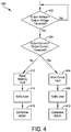
- FIG. 4 is a flow diagram 400 illustrating operation of the controller 122.
- the controller 122 monitors the output voltage of the UPS 100 and compares the output voltage to an output voltage threshold. In response to a determination that the output voltage is greater than the output voltage threshold, the controller 122 continues to monitor the output voltage of the UPS 100.
- the controller 122 monitors the output current of the UPS 100 (e.g., via the current sensor 128) and compares the output current to an output current threshold. In response to a determination that the output current threshold is greater than the output current threshold, at block 406 the controller 122 identifies that the UPS 100 is in a short circuit condition. At block 408, the controller 122 notifies the user (e.g., via a user interface or a transmission to an external system operated by the user) of the existence of the short circuit condition. At block 410, the user can take appropriate corrective action to resolve a short circuit condition (e.g., removing every load connected to the UPS 100 and individually reconnecting each load to identify the faulty load).
- a short circuit condition e.g., removing every load connected to the UPS 100 and individually reconnecting each load to identify the faulty load.
- the controller 122 In response to a determination that the output current threshold is less than the output current threshold, at block 412 the controller 122 identifies that the UPS 100 is in a welded relay condition. At block 441, the controller 122 notifies the user (e.g., via a user interface or a transmission to an external system operated by the user) of the existence of the welded relay condition. At block 160, the user can take appropriate corrective action to resolve a welded relay condition (e.g., the replacement of the AVR bypass relay 114).
- FIG. 5 illustrates an example block diagram of computing components forming a system 500 which may be configured to implement one or more aspects disclosed herein.
- the system 500 may be communicatively coupled to the controller 122 or included within the controller 122.
- the system 500 may also be configured to operate a line-interactive UPS as discussed above.
- the system 500 may include for example a computing platform such as those based on Intel PENTIUM-type processor, Motorola PowerPC, Sun UltraSPARC, Texas Instruments-DSP, Hewlett-Packard PA-RISC processors, or any other type of processor.
- System 500 may include specially-programmed, special-purpose hardware, for example, an application-specific integrated circuit (ASIC).
- ASIC application-specific integrated circuit
- Various aspects of the present disclosure may be implemented as specialized software executing on the system 500 such as that shown in FIG. 5 .
- the system 500 may include a processor/ASIC 506 connected to one or more memory devices 510, such as a disk drive, memory, flash memory or other device for storing data. Memory 510 may be used for storing programs and data during operation of the system 500.
- Components of the computer system 500 may be coupled by an interconnection mechanism 508, which may include one or more buses (e.g., between components that are integrated within a same machine) and/or a network (e.g., between components that reside on separate machines).
- the interconnection mechanism 508 enables communications (e.g., data, instructions) to be exchanged between components of the system 500.
- the system 500 also includes one or more input devices 504, which may include for example, a keyboard or a touch screen.
- the system 500 includes one or more output devices 502, which may include for example a display or user interface.
- the computer system 500 may contain one or more interfaces that may connect the computer system 500 to a communication network, in addition or as an alternative to the interconnection mechanism 508
- the system 500 may include a storage system 512, which may include a computer readable and/or writeable nonvolatile medium in which signals may be stored to provide a program to be executed by the processor or to provide information stored on or in the medium to be processed by the program.
- the medium may, for example, be a disk or flash memory and in some examples may include RAM or other non-volatile memory such as EEPROM.
- the processor may cause data to be read from the nonvolatile medium into another memory 510 that allows for faster access to the information by the processor/ASIC than does the medium.
- This memory 510 may be a volatile, random access memory such as a dynamic random access memory (DRAM) or static memory (SRAM). It may be located in storage system 512 or in memory system 510.
- DRAM dynamic random access memory
- SRAM static memory
- the processor 506 may manipulate the data within the integrated circuit memory 510 and then copy the data to the storage 512 after processing is completed.
- a variety of mechanisms are known for managing data movement between storage 512 and the integrated circuit memory element 510, and the disclosure is not limited thereto. The disclosure is not limited to a particular memory system 510 or a storage system 512.
- the system 500 may include a computer platform that is programmable using a high-level computer programming language.
- the system 500 may be also implemented using specially programmed, special purpose hardware, e.g. an ASIC.
- the system 500 may include a processor 506, which may be a commercially available processor such as the well-known Pentium class processor available from the Intel Corporation. Many other processors are available.
- the processor 506 may execute an operating system which may be, for example, a Windows operating system available from the Microsoft Corporation, MAC OS System X available from Apple Computer, the Solaris Operating System available from Sun Microsystems, or UNIX and/or LINUX available from various sources. Many other operating systems may be used.
- the processor and operating system together may form a computer platform for which application programs in high-level programming languages may be written. It should be understood that the disclosure is not limited to a particular computer system platform, processor, operating system, or network. Also, it should be apparent to those skilled in the art that the present disclosure is not limited to a specific programming language or computer system. Further, it should be appreciated that other appropriate programming languages and other appropriate computer systems could also be used.
- a system and method for accurately identifying a welded relay condition in a line-interactive UPS without requiring the physical inspection of internal components of the line-interactive UPS.
- the UPS can more accurately identify whether a short circuit condition or a welded relay condition exists in the UPS.
- appropriate corrective measures can be taken by the user to fix the UPS.
- the system and method for identifying a welded relay condition is utilized in a line-interactive UPS, As also described herein, the system and method for identifying a welded relay condition is utilized in the backup power mode of operation of a line-interactive UPS,
- the UPS includes a bidirectional DC/AC inverter circuit for both charging a backup power source and converting DC power from the backup power source into AC power.
- the UPS includes both the DC/AC inverter for converting DC power from the backup power source into AC power and a separate AC/DC converter (e.g., charger) for charging the backup power source.
Landscapes
- Business, Economics & Management (AREA)
- Emergency Management (AREA)
- Engineering & Computer Science (AREA)
- Power Engineering (AREA)
- Inverter Devices (AREA)
Claims (10)
- Ein System (100) zur unterbrechungsfreien Stromversorgung (USV), das Folgendes beinhaltet:einen Eingang (101) zum Empfangen von Eingangswechselstromleistung;einen Ausgang (118), um einer Last (124) Wechselstromausgangsleistung bereitzustellen;eine Nullverbindung;einen Transformator (112) zur automatischen Spannungsregelung (AVR, Automatic Voltage Regulation), der eine Primärwickelung und eine Sekundärwickelung aufweist; eine Vielzahl von Relais (104, 106, 108, 118), die an den Eingang, den Ausgang und die Primärwicklung gekoppelt ist, wobei die Vielzahl von Relais konfiguriert ist, um die Primärwicklung selektiv an den Eingang und den Ausgang zu koppeln;ein Bypass-Relais (114), das konfiguriert ist, um die Primärwicklung des AVR-Transformators selektiv an die Nullverbindung zu koppeln;einen Gleichstrom-Wechselstrom-Umrichterschaltkreis (116), der an die Sekundärwicklung gekoppelt ist und konfiguriert ist, um an eine Reserveleistungsquelle (126) gekoppelt zu sein und Reservegleichstromleistung von der Reserveleistungsquelle zu empfangen; undeine Steuereinheit (122), die konfiguriert ist, um die Vielzahl von Relais, das Bypass-Relais und den Gleichstrom-Wechselstrom-Umrichterschaltkreis zu betreiben, um die Ausgangswechselstromleistung, die von mindestens einer von der Eingangswechselstromleistung und der Reservegleichstromleistung abgeleitet ist, der Last bereitzustellen,wobei die Steuereinheit in einem Reserveleistungsbetriebsmodus ferner konfiguriert ist, um die Vielzahl von Relais und das Bypass-Relais zu betreiben, um den AVR-Transformator von dem Eingang zu entkoppeln und die Primärwicklung an den Ausgang zu koppeln, um den Gleichstrom-Wechselstrom-Umrichterschaltkreis zu betreiben, um die Reservegleichstromleistung in umgewandelte Wechselstromleistung umzuwandeln, die der Sekundärwicklung bereitgestellt wird, um die Wechselstromausgangsleistung zu überwachen,wobei die Steuereinheit dadurch gekennzeichnet ist, dass sie konfiguriert ist, basierend auf der überwachten Wechselstromausgangsleistung zu erkennen, dass das Bypass-Relais die Primärwicklung von der Nullverbindung in einem verschweißten Relaiszustand entkoppelt hat,wobei die Steuereinheit beim Überwachen der Wechselstromausgangsleistung ferner konfiguriert ist, um ein Ausgangsspannungsniveau und ein Ausgangsstromniveau an dem Ausgang zu überwachen,wobei die Steuereinheit ferner konfiguriert ist, um das überwachte Ausgangsspannungsniveau mit einem Ausgangsspannungsschwellenwert zu vergleichen,wobei die Steuereinheit als Antwort auf das Bestimmen, dass das Ausgangsspannungsniveau niedriger als der Ausgangsspannungsschwellenwert ist, ferner konfiguriert ist, um das Ausgangsstromniveau mit einem Ausgangsstromschwellenwert zu vergleichen, undwobei die Steuereinheit als Antwort auf das Bestimmen, dass das Ausgangsstromniveau niedriger als der Ausgangsstromschwellenwert ist, ferner konfiguriert ist, um zu erkennen, dass das Bypass-Relais die Primärwicklung von der Nullverbindung in dem verschweißten Relaiszustand entkoppelt hat.
- USV gemäß Anspruch 1, wobei die Steuereinheit als Antwort auf das Bestimmen, dass das Ausgangsstromniveau höher als der Ausgangsstromschwellenwert ist, ferner konfiguriert ist, um zu erkennen, dass die an den Ausgang gekoppelte Last kurzgeschlossen ist.
- USV gemäß Anspruch 1, wobei der AVR-Transformator ferner einen ersten Abgriff, der an eine erste Stelle der Primärwicklung gekoppelt ist, und einen zweiten Abgriff, der an eine zweite Stelle der Primärwicklung gekoppelt ist, beinhaltet und wobei die Vielzahl von Relais Folgendes beinhaltet:ein Line-Transfer-Relais, das konfiguriert ist, um den AVR-Transformator selektiv an den Eingang zu koppeln;ein Booster-Relais, das konfiguriert ist, um den ersten Abgriff selektiv an das Line-Transfer-Relais zu koppeln; undein Trimmer-Relais, das konfiguriert ist, um den zweiten Abgriff selektiv an den Ausgang zu koppeln.
- USV gemäß Anspruch 3, wobei die Steuereinheit in dem Reserveleistungsbetriebsmodus ferner konfiguriert ist, um das Line-Transfer-Relais zu betreiben, um den AVR-Transformator von dem Eingang zu entkoppeln, und um das Trimmer-Relais zu betreiben, um den zweiten Abgriff an den Ausgang zu koppeln.
- USV gemäß Anspruch 4, wobei die Steuereinheit in einem Booster-Betriebsmodus ferner konfiguriert ist, um das Line-Transfer-Relais zu betreiben, um den AVR-Transformator an den Eingang zu koppeln, um das Booster-Relais zu betreiben, um das Line-Transfer-Relais an den ersten Abgriff zu koppeln, um das Trimmer-Relais zu betreiben, um die Primärwicklung an den Ausgang zu koppeln, und um das Bypass-Relais zu betreiben, um die Primärwicklung an die Nullverbindung zu koppeln, und wobei in dem Booster-Betriebsmodus ein Spannungsniveau an dem Ausgang höher als ein Spannungsniveau an dem Eingang ist.
- USV gemäß Anspruch 4, wobei die Steuereinheit in einem Trimmer-Betriebsmodus ferner konfiguriert ist, um das Line-Transfer-Relais zu betreiben, um den AVR-Transformator an den Eingang zu koppeln, um das Booster-Relais zu betreiben, um den ersten Abgriff von dem Line-Transfer-Relais zu entkoppeln, um das Trimmer-Relais zu betreiben, um den zweiten Abgriff an den Ausgang zu koppeln, und um das Bypass-Relais zu betreiben, um die Primärwicklung an die Nullverbindung zu koppeln, und wobei in dem Trimmer-Betriebsmodus ein Spannungsniveau an dem Ausgang niedriger als ein Spannungsniveau an dem Eingang ist.
- Ein Verfahren zum Erkennen eines verschweißten Relaiszustands in einem Line-Interactive-System (100) zur unterbrechungsfreien Stromversorgung (USV), das einen Eingang (101) zum Empfangen von Eingangswechselstromleistung, einen Ausgang (118), um einer Last (124) Wechselstromausgangsleistung bereitzustellen, eine Nullverbindung, einen Transformator (112) zur automatischen Spannungsregelung, der eine Primärwickelung und eine Sekundärwickelung aufweist, eine Vielzahl von Relais (104, 106, 108, 118), die an den Eingang, den Ausgang und die Primärwicklung gekoppelt ist, wobei die Vielzahl von Relais konfiguriert ist, um die Primärwicklung selektiv an den Eingang und den Ausgang zu koppeln, ein Bypass-Relais (114), das konfiguriert ist, um die Primärwicklung des AVR-Transformators selektiv an die Nullverbindung zu koppeln, und einen Gleichstrom-Wechselstrom-Umrichterschaltkreis (116), der an die Sekundärwicklung gekoppelt ist und konfiguriert ist, um an eine Reserveleistungsquelle (126) gekoppelt zu sein und Reservegleichstromleistung von der Reserveleistungsquelle zu empfangen, beinhaltet, wobei das Verfahren folgende Vorgänge beinhaltet:Betreiben, in einem Reserveleistungsbetriebsmodus, der Vielzahl von Relais und des Bypass-Relais, um den AVR-Transformator von dem Eingang zu entkoppeln und die Primärwicklung an den Ausgang und den Gleichstrom-Wechselstrom-Umrichterschaltkreis zu koppeln, um die Wechselstromausgangsleistung, die von der Reservegleichstromleistung abgeleitet ist, der Last bereitzustellen;Überwachen der Wechselstromausgangsleistung;wobei das Verfahren dadurch gekennzeichnet ist, dass es ferner die folgenden Vorgänge beinhaltet:Bestimmen, basierend auf dem Vorgang des Überwachens, dass das Bypass-Relais die Primärwicklung von der Nullverbindung in einem verschweißten Relaiszustand entkoppelt hat,wobei das Überwachen der Wechselstromausgangsleistung Folgendes beinhaltet:Überwachen eines Ausgangsspannungsniveaus an dem Ausgang; undÜberwachen eines Ausgangsstromniveaus an dem Ausgang; undwobei das Bestimmen, ob die Line-Interactive-USV in dem verschweißten Relaiszustand ist, Folgendes beinhaltet:Vergleichen des Ausgangsspannungsniveaus mit einem Ausgangsspannungsschwellenwert;als Antwort auf das Bestimmen, dass das Ausgangsspannungsniveau niedriger als der Ausgangsspannungsschwellenwert ist, Vergleichen des Ausgangsstromniveaus mit einem Ausgangsstromschwellenwert; undals Antwort auf das Bestimmen, dass das Ausgangsstromniveau niedriger als der Ausgangsstromschwellenwert ist, Bestimmen, dass das Bypass-Relais die Primärwicklung von der Nullverbindung in dem verschweißten Relaiszustand entkoppelt hat.
- Verfahren gemäß Anspruch 7, wobei als Antwort auf das Bestimmen, dass das Ausgangsstromniveau höher als der Ausgangsstromschwellenwert ist, Bestimmen, dass die Line-Interactive-USV in einem Kurzschlusszustand ist.
- Verfahren gemäß Anspruch 7, das ferner das Betreiben, in einem Booster-Betriebsmodus, der Vielzahl von Relais und des Bypass-Relais beinhaltet, um ein Spannungsniveau an dem Ausgang zu erzeugen, das höher als ein Spannungsniveau an dem Eingang ist.
- Verfahren gemäß Anspruch 7, das ferner das Betreiben, in einem Trimmer-Betriebsmodus, der Vielzahl von Relais und des Bypass-Relais beinhaltet, um ein Spannungsniveau an dem Ausgang zu erzeugen, das niedriger als ein Spannungsniveau an dem Eingang ist.
Applications Claiming Priority (1)
| Application Number | Priority Date | Filing Date | Title |
|---|---|---|---|
| US16/025,278 US10944287B2 (en) | 2018-07-02 | 2018-07-02 | AVR bypass relay welding detection |
Publications (3)
| Publication Number | Publication Date |
|---|---|
| EP3591799A1 EP3591799A1 (de) | 2020-01-08 |
| EP3591799B1 true EP3591799B1 (de) | 2021-03-03 |
| EP3591799B8 EP3591799B8 (de) | 2021-09-08 |
Family
ID=67003274
Family Applications (1)
| Application Number | Title | Priority Date | Filing Date |
|---|---|---|---|
| EP19181964.8A Active EP3591799B8 (de) | 2018-07-02 | 2019-06-24 | Avr-bypass-relaisschweissdetektion |
Country Status (3)
| Country | Link |
|---|---|
| US (1) | US10944287B2 (de) |
| EP (1) | EP3591799B8 (de) |
| CN (1) | CN110676925B (de) |
Families Citing this family (7)
| Publication number | Priority date | Publication date | Assignee | Title |
|---|---|---|---|---|
| EP3462471B1 (de) * | 2017-09-29 | 2022-04-13 | Rockwell Automation Switzerland GmbH | Schutzschalter |
| CN110061559B (zh) * | 2019-05-24 | 2022-01-25 | 联正电子(深圳)有限公司 | 离线式不间断电源及其控制方法 |
| EP3806281B1 (de) | 2019-10-11 | 2023-07-26 | Schneider Electric IT Corporation | Verfahren zur reduzierung von ups-komponentenspannungen während des übergangs vom umrichter zum grünen bzw. bypassbetrieb |
| US20220278608A1 (en) * | 2020-08-08 | 2022-09-01 | Patrick Carden | Resonant core power supply |
| CN113433847B (zh) * | 2021-05-27 | 2022-06-17 | 东风电驱动系统有限公司 | 一种应用于不确定性继电系统的自适应控制系统 |
| CN119675214A (zh) * | 2023-09-21 | 2025-03-21 | 联正电子(深圳)有限公司 | 在线互动式不间断电源状态切换方法及不间断电源 |
| CN121734107A (zh) * | 2024-09-25 | 2026-03-27 | 斯特兰蒂斯汽车集团 | 电池包的继电器粘连的防护方法和防护系统、车辆 |
Family Cites Families (12)
| Publication number | Priority date | Publication date | Assignee | Title |
|---|---|---|---|---|
| US5602462A (en) | 1995-02-21 | 1997-02-11 | Best Power Technology, Incorporated | Uninterruptible power system |
| US6348782B1 (en) * | 1998-10-02 | 2002-02-19 | Powerware Corporation | Uninterruptible power supply systems, voltage regulators and operating methods employing controlled ferroresonant transformer circuits |
| CA2365409A1 (en) * | 1999-03-22 | 2000-09-28 | Healinx | Method and apparatus for medical covering group request processing, review and management |
| CA2489789A1 (en) | 2004-12-10 | 2006-06-10 | Xantrex International | Ac power backfeed protection based on voltage |
| US7259476B2 (en) * | 2005-04-26 | 2007-08-21 | Always “On” UPS Systems Inc. | DC and AC uninterruptible power supply |
| CN101126745A (zh) * | 2006-08-15 | 2008-02-20 | 安捷伦科技有限公司 | 用于氮磷检测器中珠开路和短路故障诊断的方法和系统 |
| US8212402B2 (en) * | 2009-01-27 | 2012-07-03 | American Power Conversion Corporation | System and method for limiting losses in an uninterruptible power supply |
| JP5945804B2 (ja) * | 2012-03-29 | 2016-07-05 | パナソニックIpマネジメント株式会社 | リレー溶着診断装置 |
| CN103378603B (zh) * | 2012-04-24 | 2017-03-01 | 通用电气公司 | 开路故障检测装置,变流器控制器,能量转换系统和方法 |
| CN104882913A (zh) | 2014-02-27 | 2015-09-02 | 伊顿制造(格拉斯哥)有限合伙莫尔日分支机构 | 一种ups电路 |
| CN104617653B (zh) * | 2015-02-15 | 2017-07-21 | 华为技术有限公司 | 一种选择性保护电路、方法及供电系统 |
| US10211670B2 (en) * | 2015-12-22 | 2019-02-19 | Schneider Electric It Corporation | UPS with integrated bypass switch |
-
2018
- 2018-07-02 US US16/025,278 patent/US10944287B2/en active Active
-
2019
- 2019-06-24 EP EP19181964.8A patent/EP3591799B8/de active Active
- 2019-07-01 CN CN201910583317.5A patent/CN110676925B/zh active Active
Non-Patent Citations (1)
| Title |
|---|
| None * |
Also Published As
| Publication number | Publication date |
|---|---|
| CN110676925B (zh) | 2023-06-27 |
| CN110676925A (zh) | 2020-01-10 |
| EP3591799A1 (de) | 2020-01-08 |
| EP3591799B8 (de) | 2021-09-08 |
| US20200006979A1 (en) | 2020-01-02 |
| US10944287B2 (en) | 2021-03-09 |
Similar Documents
| Publication | Publication Date | Title |
|---|---|---|
| EP3591799B1 (de) | Avr-bypass-relaisschweissdetektion | |
| US7615890B2 (en) | Methods and apparatus for providing uninterruptible power | |
| US5315161A (en) | Power failure detection and shut down timer | |
| EP0410716B1 (de) | Unterbrechungsfreie Stromversorgung | |
| JP2002517153A (ja) | 電源を制御するための方法および装置 | |
| KR101582850B1 (ko) | Hvdc 시스템의 전원 이중화 장치 및 그 제어방법 | |
| US9368955B2 (en) | System and method to derive power and trip a circuit breaker from an external device | |
| EP3840171B1 (de) | Systeme und verfahren zur bereitstellung von gleichstrom und wechselstrom von einer stromversorgung zu einer last | |
| AU2012362971B2 (en) | System and method for maintaining proper phase neutral wiring in a power system | |
| US5679985A (en) | Power supply with automatic recovery system | |
| KR20170116697A (ko) | 방전시 적용 가능한 하이볼티지(High-Voltage)용 연결 스위치의 패일세이프(fail-safe) 제어 장치 | |
| WO2015165121A1 (en) | Dc link voltage control | |
| CN117353442B (zh) | 一种双电源辅助切换装置的切换控制方法 | |
| JPH0739088A (ja) | 無停電電源装置 | |
| EP0063611A1 (de) | Elektrische stromversorgung für eine steuereinheit | |
| CN113287241B (zh) | 电气设备、电源系统和制造电气设备的方法 | |
| KR102874978B1 (ko) | 스마트 자가 점검 기능을 갖는 전원공급장치 및 그 제어방법 | |
| JPH09233736A (ja) | 配電線開閉器用の子局装置 | |
| KR102266188B1 (ko) | 오프라인 무정전 전원 장치 | |
| GB2640734A (en) | Smart UPS | |
| JPH10289001A (ja) | 制御システム | |
| JP2023181752A (ja) | 電源システム、電源制御装置の制御方法及びプログラム | |
| JP6061387B2 (ja) | ヒステリシス電動機用ドライブ装置 | |
| JPS6016827B2 (ja) | 交流電源装置 | |
| JP2000060024A (ja) | 直流電源装置 |
Legal Events
| Date | Code | Title | Description |
|---|---|---|---|
| PUAI | Public reference made under article 153(3) epc to a published international application that has entered the european phase |
Free format text: ORIGINAL CODE: 0009012 |
|
| STAA | Information on the status of an ep patent application or granted ep patent |
Free format text: STATUS: THE APPLICATION HAS BEEN PUBLISHED |
|
| AK | Designated contracting states |
Kind code of ref document: A1 Designated state(s): AL AT BE BG CH CY CZ DE DK EE ES FI FR GB GR HR HU IE IS IT LI LT LU LV MC MK MT NL NO PL PT RO RS SE SI SK SM TR |
|
| AX | Request for extension of the european patent |
Extension state: BA ME |
|
| STAA | Information on the status of an ep patent application or granted ep patent |
Free format text: STATUS: REQUEST FOR EXAMINATION WAS MADE |
|
| 17P | Request for examination filed |
Effective date: 20200703 |
|
| RBV | Designated contracting states (corrected) |
Designated state(s): AL AT BE BG CH CY CZ DE DK EE ES FI FR GB GR HR HU IE IS IT LI LT LU LV MC MK MT NL NO PL PT RO RS SE SI SK SM TR |
|
| GRAP | Despatch of communication of intention to grant a patent |
Free format text: ORIGINAL CODE: EPIDOSNIGR1 |
|
| STAA | Information on the status of an ep patent application or granted ep patent |
Free format text: STATUS: GRANT OF PATENT IS INTENDED |
|
| INTG | Intention to grant announced |
Effective date: 20200924 |
|
| GRAS | Grant fee paid |
Free format text: ORIGINAL CODE: EPIDOSNIGR3 |
|
| GRAA | (expected) grant |
Free format text: ORIGINAL CODE: 0009210 |
|
| STAA | Information on the status of an ep patent application or granted ep patent |
Free format text: STATUS: THE PATENT HAS BEEN GRANTED |
|
| AK | Designated contracting states |
Kind code of ref document: B1 Designated state(s): AL AT BE BG CH CY CZ DE DK EE ES FI FR GB GR HR HU IE IS IT LI LT LU LV MC MK MT NL NO PL PT RO RS SE SI SK SM TR |
|
| REG | Reference to a national code |
Ref country code: GB Ref legal event code: FG4D |
|
| RIN1 | Information on inventor provided before grant (corrected) |
Inventor name: LIN, WEI-HSIANG |
|
| REG | Reference to a national code |
Ref country code: CH Ref legal event code: EP Ref country code: AT Ref legal event code: REF Ref document number: 1368286 Country of ref document: AT Kind code of ref document: T Effective date: 20210315 |
|
| REG | Reference to a national code |
Ref country code: DE Ref legal event code: R096 Ref document number: 602019002907 Country of ref document: DE |
|
| REG | Reference to a national code |
Ref country code: IE Ref legal event code: FG4D |
|
| RAP4 | Party data changed (patent owner data changed or rights of a patent transferred) |
Owner name: SCHNEIDER ELECTRIC IT CORPORATION |
|
| REG | Reference to a national code |
Ref country code: LT Ref legal event code: MG9D |
|
| PG25 | Lapsed in a contracting state [announced via postgrant information from national office to epo] |
Ref country code: FI Free format text: LAPSE BECAUSE OF FAILURE TO SUBMIT A TRANSLATION OF THE DESCRIPTION OR TO PAY THE FEE WITHIN THE PRESCRIBED TIME-LIMIT Effective date: 20210303 Ref country code: GR Free format text: LAPSE BECAUSE OF FAILURE TO SUBMIT A TRANSLATION OF THE DESCRIPTION OR TO PAY THE FEE WITHIN THE PRESCRIBED TIME-LIMIT Effective date: 20210604 Ref country code: BG Free format text: LAPSE BECAUSE OF FAILURE TO SUBMIT A TRANSLATION OF THE DESCRIPTION OR TO PAY THE FEE WITHIN THE PRESCRIBED TIME-LIMIT Effective date: 20210603 Ref country code: HR Free format text: LAPSE BECAUSE OF FAILURE TO SUBMIT A TRANSLATION OF THE DESCRIPTION OR TO PAY THE FEE WITHIN THE PRESCRIBED TIME-LIMIT Effective date: 20210303 Ref country code: NO Free format text: LAPSE BECAUSE OF FAILURE TO SUBMIT A TRANSLATION OF THE DESCRIPTION OR TO PAY THE FEE WITHIN THE PRESCRIBED TIME-LIMIT Effective date: 20210603 Ref country code: LT Free format text: LAPSE BECAUSE OF FAILURE TO SUBMIT A TRANSLATION OF THE DESCRIPTION OR TO PAY THE FEE WITHIN THE PRESCRIBED TIME-LIMIT Effective date: 20210303 |
|
| REG | Reference to a national code |
Ref country code: NL Ref legal event code: MP Effective date: 20210303 |
|
| REG | Reference to a national code |
Ref country code: AT Ref legal event code: MK05 Ref document number: 1368286 Country of ref document: AT Kind code of ref document: T Effective date: 20210303 |
|
| REG | Reference to a national code |
Ref country code: CH Ref legal event code: PK Free format text: BERICHTIGUNG B8 |
|
| PG25 | Lapsed in a contracting state [announced via postgrant information from national office to epo] |
Ref country code: PL Free format text: LAPSE BECAUSE OF FAILURE TO SUBMIT A TRANSLATION OF THE DESCRIPTION OR TO PAY THE FEE WITHIN THE PRESCRIBED TIME-LIMIT Effective date: 20210303 Ref country code: LV Free format text: LAPSE BECAUSE OF FAILURE TO SUBMIT A TRANSLATION OF THE DESCRIPTION OR TO PAY THE FEE WITHIN THE PRESCRIBED TIME-LIMIT Effective date: 20210303 Ref country code: RS Free format text: LAPSE BECAUSE OF FAILURE TO SUBMIT A TRANSLATION OF THE DESCRIPTION OR TO PAY THE FEE WITHIN THE PRESCRIBED TIME-LIMIT Effective date: 20210303 Ref country code: SE Free format text: LAPSE BECAUSE OF FAILURE TO SUBMIT A TRANSLATION OF THE DESCRIPTION OR TO PAY THE FEE WITHIN THE PRESCRIBED TIME-LIMIT Effective date: 20210303 |
|
| PG25 | Lapsed in a contracting state [announced via postgrant information from national office to epo] |
Ref country code: NL Free format text: LAPSE BECAUSE OF FAILURE TO SUBMIT A TRANSLATION OF THE DESCRIPTION OR TO PAY THE FEE WITHIN THE PRESCRIBED TIME-LIMIT Effective date: 20210303 |
|
| PG25 | Lapsed in a contracting state [announced via postgrant information from national office to epo] |
Ref country code: EE Free format text: LAPSE BECAUSE OF FAILURE TO SUBMIT A TRANSLATION OF THE DESCRIPTION OR TO PAY THE FEE WITHIN THE PRESCRIBED TIME-LIMIT Effective date: 20210303 Ref country code: CZ Free format text: LAPSE BECAUSE OF FAILURE TO SUBMIT A TRANSLATION OF THE DESCRIPTION OR TO PAY THE FEE WITHIN THE PRESCRIBED TIME-LIMIT Effective date: 20210303 Ref country code: AT Free format text: LAPSE BECAUSE OF FAILURE TO SUBMIT A TRANSLATION OF THE DESCRIPTION OR TO PAY THE FEE WITHIN THE PRESCRIBED TIME-LIMIT Effective date: 20210303 Ref country code: SM Free format text: LAPSE BECAUSE OF FAILURE TO SUBMIT A TRANSLATION OF THE DESCRIPTION OR TO PAY THE FEE WITHIN THE PRESCRIBED TIME-LIMIT Effective date: 20210303 |
|
| PG25 | Lapsed in a contracting state [announced via postgrant information from national office to epo] |
Ref country code: IS Free format text: LAPSE BECAUSE OF FAILURE TO SUBMIT A TRANSLATION OF THE DESCRIPTION OR TO PAY THE FEE WITHIN THE PRESCRIBED TIME-LIMIT Effective date: 20210703 Ref country code: PT Free format text: LAPSE BECAUSE OF FAILURE TO SUBMIT A TRANSLATION OF THE DESCRIPTION OR TO PAY THE FEE WITHIN THE PRESCRIBED TIME-LIMIT Effective date: 20210705 Ref country code: RO Free format text: LAPSE BECAUSE OF FAILURE TO SUBMIT A TRANSLATION OF THE DESCRIPTION OR TO PAY THE FEE WITHIN THE PRESCRIBED TIME-LIMIT Effective date: 20210303 Ref country code: SK Free format text: LAPSE BECAUSE OF FAILURE TO SUBMIT A TRANSLATION OF THE DESCRIPTION OR TO PAY THE FEE WITHIN THE PRESCRIBED TIME-LIMIT Effective date: 20210303 |
|
| REG | Reference to a national code |
Ref country code: DE Ref legal event code: R097 Ref document number: 602019002907 Country of ref document: DE |
|
| PLBE | No opposition filed within time limit |
Free format text: ORIGINAL CODE: 0009261 |
|
| STAA | Information on the status of an ep patent application or granted ep patent |
Free format text: STATUS: NO OPPOSITION FILED WITHIN TIME LIMIT |
|
| PG25 | Lapsed in a contracting state [announced via postgrant information from national office to epo] |
Ref country code: ES Free format text: LAPSE BECAUSE OF FAILURE TO SUBMIT A TRANSLATION OF THE DESCRIPTION OR TO PAY THE FEE WITHIN THE PRESCRIBED TIME-LIMIT Effective date: 20210303 Ref country code: MC Free format text: LAPSE BECAUSE OF FAILURE TO SUBMIT A TRANSLATION OF THE DESCRIPTION OR TO PAY THE FEE WITHIN THE PRESCRIBED TIME-LIMIT Effective date: 20210303 Ref country code: AL Free format text: LAPSE BECAUSE OF FAILURE TO SUBMIT A TRANSLATION OF THE DESCRIPTION OR TO PAY THE FEE WITHIN THE PRESCRIBED TIME-LIMIT Effective date: 20210303 Ref country code: DK Free format text: LAPSE BECAUSE OF FAILURE TO SUBMIT A TRANSLATION OF THE DESCRIPTION OR TO PAY THE FEE WITHIN THE PRESCRIBED TIME-LIMIT Effective date: 20210303 |
|
| 26N | No opposition filed |
Effective date: 20211206 |
|
| PG25 | Lapsed in a contracting state [announced via postgrant information from national office to epo] |
Ref country code: SI Free format text: LAPSE BECAUSE OF FAILURE TO SUBMIT A TRANSLATION OF THE DESCRIPTION OR TO PAY THE FEE WITHIN THE PRESCRIBED TIME-LIMIT Effective date: 20210303 |
|
| REG | Reference to a national code |
Ref country code: BE Ref legal event code: MM Effective date: 20210630 |
|
| PG25 | Lapsed in a contracting state [announced via postgrant information from national office to epo] |
Ref country code: LU Free format text: LAPSE BECAUSE OF NON-PAYMENT OF DUE FEES Effective date: 20210624 |
|
| PG25 | Lapsed in a contracting state [announced via postgrant information from national office to epo] |
Ref country code: IT Free format text: LAPSE BECAUSE OF FAILURE TO SUBMIT A TRANSLATION OF THE DESCRIPTION OR TO PAY THE FEE WITHIN THE PRESCRIBED TIME-LIMIT Effective date: 20210303 Ref country code: IE Free format text: LAPSE BECAUSE OF NON-PAYMENT OF DUE FEES Effective date: 20210624 |
|
| PG25 | Lapsed in a contracting state [announced via postgrant information from national office to epo] |
Ref country code: IS Free format text: LAPSE BECAUSE OF FAILURE TO SUBMIT A TRANSLATION OF THE DESCRIPTION OR TO PAY THE FEE WITHIN THE PRESCRIBED TIME-LIMIT Effective date: 20210703 |
|
| PG25 | Lapsed in a contracting state [announced via postgrant information from national office to epo] |
Ref country code: BE Free format text: LAPSE BECAUSE OF NON-PAYMENT OF DUE FEES Effective date: 20210630 |
|
| REG | Reference to a national code |
Ref country code: CH Ref legal event code: PL |
|
| PG25 | Lapsed in a contracting state [announced via postgrant information from national office to epo] |
Ref country code: LI Free format text: LAPSE BECAUSE OF NON-PAYMENT OF DUE FEES Effective date: 20220630 Ref country code: CH Free format text: LAPSE BECAUSE OF NON-PAYMENT OF DUE FEES Effective date: 20220630 |
|
| PG25 | Lapsed in a contracting state [announced via postgrant information from national office to epo] |
Ref country code: CY Free format text: LAPSE BECAUSE OF FAILURE TO SUBMIT A TRANSLATION OF THE DESCRIPTION OR TO PAY THE FEE WITHIN THE PRESCRIBED TIME-LIMIT Effective date: 20210303 |
|
| PG25 | Lapsed in a contracting state [announced via postgrant information from national office to epo] |
Ref country code: HU Free format text: LAPSE BECAUSE OF FAILURE TO SUBMIT A TRANSLATION OF THE DESCRIPTION OR TO PAY THE FEE WITHIN THE PRESCRIBED TIME-LIMIT; INVALID AB INITIO Effective date: 20190624 |
|
| PG25 | Lapsed in a contracting state [announced via postgrant information from national office to epo] |
Ref country code: MK Free format text: LAPSE BECAUSE OF FAILURE TO SUBMIT A TRANSLATION OF THE DESCRIPTION OR TO PAY THE FEE WITHIN THE PRESCRIBED TIME-LIMIT Effective date: 20210303 |
|
| PG25 | Lapsed in a contracting state [announced via postgrant information from national office to epo] |
Ref country code: MT Free format text: LAPSE BECAUSE OF FAILURE TO SUBMIT A TRANSLATION OF THE DESCRIPTION OR TO PAY THE FEE WITHIN THE PRESCRIBED TIME-LIMIT Effective date: 20210303 |
|
| PGFP | Annual fee paid to national office [announced via postgrant information from national office to epo] |
Ref country code: DE Payment date: 20250626 Year of fee payment: 7 |
|
| PGFP | Annual fee paid to national office [announced via postgrant information from national office to epo] |
Ref country code: GB Payment date: 20250617 Year of fee payment: 7 |
|
| PGFP | Annual fee paid to national office [announced via postgrant information from national office to epo] |
Ref country code: FR Payment date: 20250624 Year of fee payment: 7 |
|
| PG25 | Lapsed in a contracting state [announced via postgrant information from national office to epo] |
Ref country code: TR Free format text: LAPSE BECAUSE OF FAILURE TO SUBMIT A TRANSLATION OF THE DESCRIPTION OR TO PAY THE FEE WITHIN THE PRESCRIBED TIME-LIMIT Effective date: 20210303 |