EP3591795B1 - Batterieladeverfahren und elektronische vorrichtung - Google Patents
Batterieladeverfahren und elektronische vorrichtung Download PDFInfo
- Publication number
- EP3591795B1 EP3591795B1 EP19182986.0A EP19182986A EP3591795B1 EP 3591795 B1 EP3591795 B1 EP 3591795B1 EP 19182986 A EP19182986 A EP 19182986A EP 3591795 B1 EP3591795 B1 EP 3591795B1
- Authority
- EP
- European Patent Office
- Prior art keywords
- charging
- current
- voltage
- voltage direct
- battery
- Prior art date
- Legal status (The legal status is an assumption and is not a legal conclusion. Google has not performed a legal analysis and makes no representation as to the accuracy of the status listed.)
- Active
Links
Images



Classifications
-
- H—ELECTRICITY
- H02—GENERATION; CONVERSION OR DISTRIBUTION OF ELECTRIC POWER
- H02J—ELECTRIC POWER NETWORKS; CIRCUIT ARRANGEMENTS OR SYSTEMS FOR SUPPLYING OR DISTRIBUTING ELECTRIC POWER; SYSTEMS FOR STORING ELECTRIC ENERGY
- H02J7/00—Circuit arrangements for charging or discharging batteries or for supplying loads from batteries
-
- H—ELECTRICITY
- H02—GENERATION; CONVERSION OR DISTRIBUTION OF ELECTRIC POWER
- H02J—ELECTRIC POWER NETWORKS; CIRCUIT ARRANGEMENTS OR SYSTEMS FOR SUPPLYING OR DISTRIBUTING ELECTRIC POWER; SYSTEMS FOR STORING ELECTRIC ENERGY
- H02J7/00—Circuit arrangements for charging or discharging batteries or for supplying loads from batteries
- H02J7/90—Regulation of charging or discharging current or voltage
- H02J7/92—Regulation of charging or discharging current or voltage with prioritisation of loads or sources
-
- H—ELECTRICITY
- H02—GENERATION; CONVERSION OR DISTRIBUTION OF ELECTRIC POWER
- H02J—ELECTRIC POWER NETWORKS; CIRCUIT ARRANGEMENTS OR SYSTEMS FOR SUPPLYING OR DISTRIBUTING ELECTRIC POWER; SYSTEMS FOR STORING ELECTRIC ENERGY
- H02J7/00—Circuit arrangements for charging or discharging batteries or for supplying loads from batteries
- H02J7/60—Circuit arrangements for charging or discharging batteries or for supplying loads from batteries including safety or protection arrangements
-
- H—ELECTRICITY
- H02—GENERATION; CONVERSION OR DISTRIBUTION OF ELECTRIC POWER
- H02J—ELECTRIC POWER NETWORKS; CIRCUIT ARRANGEMENTS OR SYSTEMS FOR SUPPLYING OR DISTRIBUTING ELECTRIC POWER; SYSTEMS FOR STORING ELECTRIC ENERGY
- H02J7/00—Circuit arrangements for charging or discharging batteries or for supplying loads from batteries
- H02J7/60—Circuit arrangements for charging or discharging batteries or for supplying loads from batteries including safety or protection arrangements
- H02J7/64—Circuit arrangements for charging or discharging batteries or for supplying loads from batteries including safety or protection arrangements against overvoltage
-
- H—ELECTRICITY
- H02—GENERATION; CONVERSION OR DISTRIBUTION OF ELECTRIC POWER
- H02J—ELECTRIC POWER NETWORKS; CIRCUIT ARRANGEMENTS OR SYSTEMS FOR SUPPLYING OR DISTRIBUTING ELECTRIC POWER; SYSTEMS FOR STORING ELECTRIC ENERGY
- H02J7/00—Circuit arrangements for charging or discharging batteries or for supplying loads from batteries
- H02J7/90—Regulation of charging or discharging current or voltage
-
- H—ELECTRICITY
- H02—GENERATION; CONVERSION OR DISTRIBUTION OF ELECTRIC POWER
- H02J—ELECTRIC POWER NETWORKS; CIRCUIT ARRANGEMENTS OR SYSTEMS FOR SUPPLYING OR DISTRIBUTING ELECTRIC POWER; SYSTEMS FOR STORING ELECTRIC ENERGY
- H02J7/00—Circuit arrangements for charging or discharging batteries or for supplying loads from batteries
- H02J7/90—Regulation of charging or discharging current or voltage
- H02J7/933—Regulation of charging or discharging current or voltage the cycle being controlled or terminated in response to electric parameters
-
- H—ELECTRICITY
- H02—GENERATION; CONVERSION OR DISTRIBUTION OF ELECTRIC POWER
- H02J—ELECTRIC POWER NETWORKS; CIRCUIT ARRANGEMENTS OR SYSTEMS FOR SUPPLYING OR DISTRIBUTING ELECTRIC POWER; SYSTEMS FOR STORING ELECTRIC ENERGY
- H02J7/00—Circuit arrangements for charging or discharging batteries or for supplying loads from batteries
- H02J7/90—Regulation of charging or discharging current or voltage
- H02J7/94—Regulation of charging or discharging current or voltage in response to battery current
Definitions
- the present disclosure relates to the field of electronic technologies, and in particular to a charging method and an electronic device.
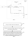
- FIG. 1 shows a schematic view of a structure of the electronic device which comprises a charging interface 101, a charging circuit 102 and a battery 103.
- the charging circuit 102 comprises a high-voltage direct-charging chip 1021.
- An output end of the charging interface 101 is connected to an input end of the high-voltage direct-charging chip 1021.
- An output end of the high-voltage direct-charging chip 1021 is connected to the battery 103.
- a charger is connected to the charging interface 101 and outputs a first voltage and a first current to the high-voltage direct-charging chip 1021 through the charging interface 101.
- the high-voltage direct-charging chip 1021 doubles the current while halving the voltage to obtain a target voltage that is half of the first voltage and a target current that is two times of the first current.
- the target voltage and the target current are output to the battery 103. In this way, a low voltage and a high current are output to the battery 103 after a high voltage and a low current are input into the high-voltage direct-charging chip 1021.
- the characteristic of high charging current is achieved.
- US 2017/077719 discloses a battery charging system and using the battery charging system to charge a battery to a target charge level using multiple constant current stages and without using a constant voltage stage.
- US 2018/069407 discloses a soft start amplifier providing a soft-start function that controls a battery charging current in a feedback loop charging circuit by selecting the lowest voltage between a soft start voltage and an error derived control voltage.
- the lowest voltage is used as a control signal for controlling the battery charging current in the feedback loop charging circuit.
- the error voltage is a difference between a voltage proportional to the charging current and a voltage proportional to the target charging current while the soft start voltage is a voltage configured to ramp up with time.
- US 2018/034296 discloses a charging system.
- the system includes a power adapter and a terminal.
- the power adapter includes a first rectifier, a switch unit, a transformer, a second rectifier, a sampling unit, and a control unit.
- the control unit outputs a control signal to the switch unit, and adjusts a duty ratio of the control signal according to coupled sampling performed by the sampling unit at an auxiliary winding, such that a third voltage outputted by the second rectifier meets a charging requirement.
- the terminal includes a battery. When the power adapter is coupled to the terminal, the third voltage is applied to the battery.
- the present disclosure provides a charging method and a system comprising a charger and an electronic device.
- the technical solutions are as follows.
- the charging current is output to the battery after being increased by the first predetermined current through the high-voltage direct-charging chip every time till the charging current reaches the first target current, such that the voltage of the battery is increased slowly to reserve enough time for detection.
- the voltage of the battery may not exceed a safety voltage because a voltage rise of the battery may be successfully detected in time. Accordingly, the safety is improved.
- the battery is charged by means of stepped reduction of the charging current.
- the voltage of the battery is slowly increased and prevented from being too high.
- charging is fully conducted under the condition of ensuring the safety of the battery.
- the line impedance between the output end of the charger and the input end of the high-voltage direct-charging chip is obtained in a pre-charging stage. Whether the electronic device may be charged by the high-voltage direct-charging technology is judged. The charging efficiency may be improved without an excessive voltage drop when the high-voltage direct-charging technology is adopted for charging.
- a high-voltage direct-charging technology and a low-voltage direct-charging technology are introduced first.
- the high-voltage direct-charging technology lies in that a voltage/current output by a charger end is output to a high-voltage direct-charging chip, and the high-voltage direct-charging chip halves the voltage and doubles the current to obtain a target current, and then outputs the target current to a battery to realize high-current charging.
- the low-voltage direct-charging technology lies in that a current output by a charger end is output to a master charging chip, and the master charging chip directly outputs the current to a battery to charge the battery without halving the voltage.
- FIG. 2 is a schematic view illustrating a structure of an electronic device according to an exemplary aspect.
- the electronic device includes a charging interface 201, a charging circuit 202 and a battery 203.
- the charging circuit 202 includes a high-voltage direct-charging chip 2021.
- An output end of the charging interface 201 is connected to an input end of the high-voltage direct-charging chip 2021.
- An output end of the high-voltage direct-charging chip 2021 is connected to the battery 203 to output a charging current to the battery 203.
- a charger is connected to the charging interface 201 and outputs a current to the charging interface 201. Then, the charging interface 201 outputs the current to the high-voltage direct-charging chip 2021.
- the high-voltage direct-charging chip 2021 outputs a charging current to the battery 203 to charge the battery 203.
- the high-voltage direct-charging chip 2021 obtains a first target current by stepped increase of the current instead of halving a voltage and doubling the current.
- the charging current is output to the battery 203 after being increased by a first predetermined current every time till the charging current reaches the first target current. Therefore, the voltage of the battery 203 is slowly increased. It is ensured that a voltage rise of the battery can be detected in time. The situation that the voltage of the battery exceeds a safety voltage due to the failure to detect the rise of the battery voltage in time can be avoided. Accordingly, the safety is improved.
- the charging circuit 202 further includes a master charging chip 2022.
- the output end of the charging interface 201 is connected to an input end of the master charging chip 2022.
- An output end of the master charging chip 2022 is connected to the battery 203.
- the high-voltage direct-charging chip 2021 charges the battery 203 and the charging current reaches a second target current, the high-voltage direct-charging chip 2021 may be turned off, and the master charging chip 2022 charges the battery 203.
- FIG. 4 is a flowchart of a charging method according to an exemplary aspect. As shown in FIG. 4 , the charging method includes the following steps:
- a high-voltage direct-charging chip rapidly doubles the charging current to obtain the target current, and output the target current to the battery, resulting in that the voltage of the battery rises quickly and easily exceeds the safety voltage.
- the detection mechanism of the charging circuit usually lags behind the rise of the battery voltage, and thus, cannot timely detect the event that the voltage of the battery exceeds the safety voltage such that the battery cannot be protected in time.
- the aforesaid overvoltage phenomenon occurs repeatedly, it will lead to a safety hazard.
- the charging current is output to the battery after being increased by a first predetermined current every time through the high-voltage direct-charging chip till the charging current reaches a first target current, such that the voltage of the battery is increased slowly to reserve enough time for detection.
- a first predetermined current every time through the high-voltage direct-charging chip till the charging current reaches a first target current, such that the voltage of the battery is increased slowly to reserve enough time for detection.
- the method further comprises: when the charging current reaches the first target current, after reducing the charging current by a second predetermined current every time, outputting the reduced charging current to the battery through the high-voltage direct-charging chip till the charging current reaches a second target current which is the charging current when the battery is fully charged, in which the second target current is lower than the first target current.
- the method further comprises:
- the charging circuit further comprises a master charging chip, the output end of the charging interface is connected to an input end of the master charging chip, an output end of the master charging chip is connected to the battery, and the charging method further comprises: when the charging current reaches the second target current, turning off the high-voltage direct-charging chip and turning on the master charging chip.
- an input end of the charging interface is connected to an output end of a charger, and the charging method further comprises:
- the method further comprises:
- the method further comprises: when a difference value between the first line impedance and the second line impedance is greater than a predetermined threshold, turning off the high-voltage direct-charging chip, outputting the second current to the high-voltage direct-charging chip by the charging interface, and re-executing the step of obtaining the first line impedance.
- FIG. 5 is a flow chart of a charging method according to an exemplary aspect.
- FIG. 6 and FIG. 7 are schematic views of current flow directions according to an exemplary aspect. As shown in FIGs. 5-7 , the charging method includes the following steps.
- step 501 the high-voltage direct-charging chip is turned on, and the first current is output to the high-voltage direct-charging chip by the charging interface.
- the high-voltage direct-charging chip is t while the master charging chip is turned off.
- the charger is connected to the charging interface through a data cable and outputs the current to the charging interface.
- the charging interface outputs the first current to the high-voltage direct-charging chip.
- the schematic view of the current flow direction in the charging process may be as shown in FIG. 6 .
- step 502 after increasing the charging current by the first predetermined current every time, the increased charging current is output to the battery by the high-voltage direct-charging chip till the charging current reaches the first target current.
- the battery has the safety voltage. It is believed that the battery is in a safe state when the voltage of the battery is lower than the safety voltage. When the voltage of the battery is greater than or equal to the safety voltage, it means that the battery has an excessive voltage which may impact the safety of the battery.
- the working current of the high-voltage direct-charging chip is the first target current
- the charging current needs to be increased to the first target current and the first target current is adopted to charge the battery when the high-voltage direct-charging chip charges the battery.
- the specific value of the first target current may be determined in accordance with the working performance of the high-voltage direct-charging chip.
- the voltage of the battery may be rapidly increased and thus may exceed the safety voltage to lead to a safety hazard.
- R represents internal resistance of the battery
- I represents the charging current
- a voltage U1 consumed on the internal resistance of the battery is equal to R*I.
- U2 the electricity quantity of the battery
- U of the battery which may be detected
- U1+U2 the voltage U of the battery, which may be detected
- U may not be more than the safety voltage.
- the charging current I is increased rapidly, the voltage U of the battery is also increased rapidly.
- the voltage U of the battery may easily exceed the safety voltage if a user still performs charging.
- the high-voltage direct-charging chip receives the first current output by the charging interface. Instead of directly doubling the first current to obtain the first target current and outputting the obtained first target current to the battery, a stepped current increase mode is adopted to output the charging current which is increased by the first predetermined current every time to the battery, such that the voltage of the battery is slowly increased till the charging current reaches the first target current.
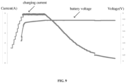
- the current is increased with a step of 200 mA every time till the charging current is increased to 5A.
- step 503 when the charging current reaches the first target current, after increasing the charging current by the first predetermined current every time, the increased charging current is output to the battery by the high-voltage direct-charging chip till the charging current reaches a second target current.
- the second target current is lower than the first target current.
- the high-voltage direct-charging chip Owing to the relatively higher charging current provided by the high-voltage direct-charging chip, and under the action of the internal resistance in the battery, the battery is actually not fully charged when the charging current reaches the first target current. Thus, at this time, the high-voltage direct-charging chip continuously performs charging instead of being turned off.
- the high-voltage direct-charging chip may reduce the charging current by the second predetermined value and then output the reduced charging current to the battery.
- the battery is charged by means of stepped current reduction.
- the voltage of the battery is slowly increased and prevented from being too high.
- the safety of the battery in the charging process is guaranteed.
- the second target current refers to the charging current when the battery is fully charged.
- the specific value thereof may be determined in accordance with the performance of the battery. It can be considered that the battery is fully charged when the charging current reaches the second target current.
- the charging current when the charging current reaches the first target current, the charging current is output to the battery after being reduced by the second predetermined current every time through the high-voltage direct-charging chip.
- the charging current when the charging current reaches a third target current, the charging current is output to the battery after being reduced by a third predetermined current every time till the charging current reaches the second target current.
- the third predetermined current is lower than the second predetermined current.
- the second target current is lower than the first target current.
- the third predetermined current is lower than the first target current and higher than the second target current.
- the high-voltage direct-charging chip continuously provides the charging current for the battery
- the voltage of the battery is gradually increased to be approximate to the safety voltage.
- the charging current may be reduced by the smaller third predetermined current after being reduced by the second predetermined current, such that the voltage of the battery is slowly increased with a smaller amplitude.
- the charging current when the charging current is 5A, the charging current may be output to the battery after being reduced by 1A every time through the high-voltage direct-charging chip.
- the charging current is 2A, the amplitude 1A of the original current reduction is adjusted to 200 mA, and the charging current is reduced by 200 mA every time and then output to the battery.
- the second predetermined current and the third predetermined current may be determined in accordance with the demands on the charging efficiency and the charging sufficiency.
- step 504 when the charging current reaches the second target current, the high-voltage direct-charging chip is turned off and the master charging chip is turned on to charge the battery.
- the schematic view of a current flow direction in the charging process may be as shown in FIG. 7 .
- the aspect of the present disclosure provides the charging method, the charging current is output to the battery after being increased by the first predetermined current every time through the high-voltage direct-charging chip till the charging current reaches the first target current, such that the voltage of the battery is increased slowly to reserve enough time for detection.
- the situation that the voltage of the battery exceeds a safety voltage due to the failure to detect the increase of the battery voltage in time can be avoided. Accordingly, the safety is improved. Some emergencies may be dealt with timely.
- Advantages and disadvantages of the high-voltage direct-charging technology are analyzed, such that the high-voltage direct-charging technology may be played better.
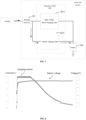
- FIG. 8 is a schematic view of a charging current and a battery voltage that are provided by the related art.
- FIG. 9 is a schematic view of a charging current and a battery voltage that are provided by an aspect of the present disclosure.
- FIG. 10 is a flow chart of a charging method according to an exemplary aspect. As shown in FIG. 10 , the charging method includes the following steps.
- step 1001 a second current is output to the high-voltage direct-charging chip through the charging interface under the condition that the high-voltage direct-charging chip is turned off.
- the high-voltage direct-charging chip is turned off.
- a charger is connected to the charging interface and outputs a current to the charging interface.
- the charging interface outputs the second current to the high-voltage direct-charging chip.
- the second current may be a relatively lower current, for example, a current of 500 mA to 1 A.
- step 1002 a voltage at an output end of the charger and a voltage at an input end of the high-voltage direct-charging chip are acquired.
- the charger is connected to the charging interface through a data cable.
- the voltage at the output end of the charger may be detected and sent to an electronic device through the data cable and the charging interface, such that the electronic device may acquire the voltage at the output end of the charger.
- the electronic device may further detect the voltage at the input end of the high-voltage direct-charging chip.
- step 1003 a line impedance between the charger and the high-voltage direct-charging chip is obtained as a first line impedance in accordance with the second current, the voltage at the output end of the charger and the voltage at the input end of the high-voltage direct-charging chip.
- a voltage difference between the voltage at the output end of the charger and the voltage at the input end of the high-voltage direct-charging chip is calculated.
- a quotient of the voltage difference to the second current is calculated as the first line impedance. If V1 represents the voltage at the output end of the charger, V2 represents the voltage at the input end of the high-voltage direct-charging chip and I represents the second current, the first line impedance is (V1-V2)/I.
- the high-voltage direct-charging chip can be turned on to charge the battery.
- the first line impedance when the first line impedance is greater than or equal to the predetermined impedance, it means that the line impedance between the charger and the high-voltage direct-charging chip is too large, and the charging efficiency may still be reduced when the high-voltage direct-charging technology is adopted.
- the high-voltage direct-charging chip is turned off, and the master charging chip is turned on to charge the battery.
- step 1005 a first current is output to the high-voltage direct-charging chip by the charging interface.
- the charger After the high-voltage direct-charging chip is turned on, the charger outputs a current to the charging interface.
- the charging interface outputs the first current to the high-voltage direct-charging chip.
- the step 1005 and the step 401 are similar to each other and are different in that the step 1005 is the formal charging stage, the first current is higher than the second current in the pre-charging stage.
- step 1007 a line impedance between the charger and the high-voltage direct-charging chip is obtained as a second line impedance in accordance with the first current, the voltage at the output end of the charger and the voltage at the input end of the high-voltage direct-charging chip.
- a calculation mode of the second line impedance is similar to that of the first line impedance in the steps 1001-1003, and will not be repeated herein.
- step 1007 the step 1001 is re-executed when a difference value between the second line impedance and the first line impedance is greater than a predetermined threshold.
- the second line impedance is compared with the first line impedance obtained in the pre-charging stage, and the difference value therebetween is calculated.
- the difference value between the first line impedance and the second line impedance is greater than the predetermined threshold, it means that the difference between the line impedances obtained twice is too large.
- a calculation error such as a voltage detection error or poor plugging in of a plug of the charger, may occur.
- the high-voltage direct-charging chip is turned off.
- the first line impedance is obtained again, such that a mechanism for impedance re-detection is added. Thus, the safety of the battery is guaranteed.
- the difference value between the second line impedance and the first line impedance is less than or equal to the predetermined threshold, it means that the obtained line impedance is accurate. Then, charging may be continuously performed.
- the line impedance between the output end of the charger and the input end of the high-voltage direct-charging chip is obtained in the pre-charging stage, such that the line impedance is estimated and whether the electronic device may be charged by the high-voltage direct-charging technology is judged.
- basic data are provided for the follow-up high-voltage direct-charging process.
- the charging efficiency can be improved when the high-voltage direct-charging technology is adopted for charging without excessive voltage drop.
- the charging current is output to the battery after being increased by the first predetermined current through the high-voltage direct-charging chip every time till the charging current reaches the first target current, such that the voltage of the battery is increased slowly to reserve enough time for detection.
- the voltage of the battery may not exceed a safety voltage because a voltage rise of the battery may be successfully detected in time. Accordingly, the safety is improved.
- the battery is charged by means of stepped reduction of the charging current.
- the voltage of the battery is slowly increased and prevented from being too high.
- charging is fully conducted under the condition of ensuring the safety of the battery.
- the line impedance between the output end of the charger and the input end of the high-voltage direct-charging chip is obtained in a pre-charging stage. Whether the electronic device may be charged by the high-voltage direct-charging technology is judged. The charging efficiency may be improved without an excessive voltage drop when the high-voltage direct-charging technology is adopted for charging.
Landscapes
- Engineering & Computer Science (AREA)
- Power Engineering (AREA)
- Charge And Discharge Circuits For Batteries Or The Like (AREA)
Claims (6)
- Ladeverfahren, angewendet auf eine elektronische Vorrichtung und ein Ladegerät, wobei die elektronische Vorrichtung ein Ladeinterface (201), eine Ladeschaltung (202), und eine Batterie (203) aufweist, wobei die Ladeschaltung (202) einen Hochspannung-Direktladechip (2021) aufweist, wobei das Verfahren die folgenden Schritte aufweisen:Einschalten des Hochspannung-Direktladechips (2021), um das Ausgeben eines Ladestroms an die Batterie (203) zu ermöglichen, wobei ein Ausgangsende des Ladeinterface (201) mit einem Eingangsende des Hochspannung-Direktladechips (2021) verbunden ist, ein Ausgangsende des Hochspannung-Direktladechips (2021) mit der Batterie (203) verbunden ist, und der Hochspannung-Direktladechip (2021) eine Spannung halbiert und einen Strom verdoppelt, um den Ladestrom zu erhalten;Ausgeben, durch das Ladegerät, eines ersten Stroms an den Hochspannung-Direktladechip (2021) durch das Ladeinterface (201); undjeweiliges Erhöhen des Ladestroms um einen ersten vorbestimmten Strom und anschließendes Ausgeben des Ladestroms an die Batterie (203) durch den Hochspannung-Direktladechip (2021), bis der Ladestrom einen ersten Zielstrom erreicht, welcher ein Arbeitsstrom des Hochspannung-Direktladechips (2021) ist; undwobei das Verfahren ferner den folgenden Schritt aufweist:
wenn der Ladestrom den ersten Zielstrom erreicht, jeweiliges Verringern des Ladestroms um einen zweiten vorbestimmten Strom und anschließendes Ausgeben des verringerten Ladestroms an die Batterie (203) durch den Hochspannung-Direktladechip (2021), bis der verringerte Ladestrom einen zweiten Zielstrom erreicht, wobei der zweite Zielstrom der Ladestrom ist, wenn die Batterie (203) vollständig geladen ist, und geringer als der erste Zielstrom ist;dadurch gekennzeichnet, dassein Eingangsende des Ladeinterface (201) mit einem Ausgangsende des Ladegeräts verbunden ist, wobei das Verfahren ferner die folgenden Schritte aufweist:Ausgeben, durch das Ladegerät, eines zweiten Stroms, der geringer als der erste Strom ist, an den Hochspannung-Direktladechip (2021) durch das Ladeinterface (201) unter der Bedingung, dass der Hochspannung-Direktladechip (2021) ausgeschaltet ist;Erfassen einer Spannung am Ausgangsende des Ladegeräts und einer Spannung an dem Eingangsende des Hochspannung-Direktladechips (2021);Ermitteln einer ersten Leitungsimpedanz zwischen dem Ladegerät und dem Hochspannung-Direktladechip (2021) gemäß dem zweiten Strom, der Spannung an dem Ausgangsende des Ladegeräts und der Spannung an dem Eingangsende des Hochspannung-Direktladechips (2021); undEinschalten des Hochspannung-Direktladechips (2021), wenn die erste Leitungsimpedanz geringer als eine vorbestimmte Impedanz ist. - Verfahren nach Anspruch 1, ferner mit den Schritten:wenn der Ladestrom den ersten Ladestrom erreicht, jeweiliges Verringern des Ladestroms um einen zweiten vorbestimmten Ladestrom und anschließendes Ausgeben des verringerten Ladestroms an die Batterie (203) durch den Hochspannung-Direktladechip (2021); undwenn der Ladestrom einen dritten Zielstrom erreicht, jeweiliges Verringern des Ladestroms durch einen dritten vorbestimmten Strom und anschließendes Ausgeben des verringerten Ladestroms an die Batterie (203), bis der Ladestrom einen zweiten Zielstrom erreicht, wobei der zweite Ladestrom der Ladestrom ist, wenn die Batterie (203) vollständig geladen ist, der dritte vorbestimmte Strom geringer als der zweite vorbestimmte Strom ist, der zweite Zielstrom geringer als der erste Zielstrom ist, und der dritte vorbestimmte Strom geringer als der erste Zielstrom und höher als der zweite Zielstrom ist.
- Verfahren nach Anspruch 1 oder Anspruch 2, bei welchem die Lageschaltung (202) ferner einen Master-Ladechip (2022) aufweist, das Ausgangsende des Ladeinterface (201) mit einem Eingangsende des Master-Ladechips (2022) verbunden ist, ein Ausgangsende des Master-Ladechips (2022) mit der Batterie (203) verbunden ist, wobei das Verfahren den folgenden Schritt aufweist:
wenn der Ladestrom den zweiten Zielstrom erreicht, Abschalten des Hochspannung-Direktladechips (2021) und Einschalten des Master-Ladechips (2022), um die Batterie unter Verwendung einer Niederspannung-Direktladetechnologie zu laden. - Ladeverfahren nach Anspruch 1, ferner mit den Schritten:Erfassen der Spannung am Ausgangsende des Ladegeräts und der Spannung am Eingangsende des Hochspannung-Direktladechips (2021) in einem Vorgang, bei welchem das Ladegerät den ersten Strom durch das Ladeinterface (201) an den Hochspannung-Direktladechip (2021) ausgibt; undErmitteln einer zweiten Leitungsimpedanz zwischen dem Ladegerät und dem Hochspannung-Direktladechip (2021) gemäß dem ersten Strom, der Spannung am Ausgangsende des Ladegeräts und der Spannung am Eingangsende des Hochspannung-Direktladechips (2021).
- Ladeverfahren nach Anspruch 4, ferner mit dem Schritt:
wenn ein Differenzwert zwischen der ersten Leitungsimpedanz und der zweiten Leitungsimpedanz größer als ein vorbestimmter Schwellenwert ist, Abschalten des Hochspannung-Direktladechips (2021), Ausgeben des zweiten Stroms zum Hochspannung-Direktladechip (2021) über das Ladeinterface (201), und erneutes Ausführen des Schritts des Ermittelns der ersten Leitungsimpedanz. - System mit einem Ladegerät und einer elektronischen Vorrichtung, bei welchemdie elektronische Vorrichtung ein Ladeinterface (201), eine Ladeschaltung (202), und eine Batterie (203) aufweist,wobei die Ladeschaltung (202) einen Hochspannung-Direktladechip (2021) aufweist, ein Ausgangsende des Ladeinterface (201) mit einem Eingangsende des Hochspannung-Direktladechips (2021) verbunden ist, und ein Ausgangsende des Hochspannung-Direktladechips (2021) mit der Batterie (203) verbunden ist; unddas System dazu ausgebildet ist, das Ladeverfahren nach einem der Ansprüche 1-5 auszuführen.
Applications Claiming Priority (1)
| Application Number | Priority Date | Filing Date | Title |
|---|---|---|---|
| CN201810716578.5A CN108847699B (zh) | 2018-07-03 | 2018-07-03 | 充电方法及电子设备 |
Publications (2)
| Publication Number | Publication Date |
|---|---|
| EP3591795A1 EP3591795A1 (de) | 2020-01-08 |
| EP3591795B1 true EP3591795B1 (de) | 2025-05-21 |
Family
ID=64200145
Family Applications (1)
| Application Number | Title | Priority Date | Filing Date |
|---|---|---|---|
| EP19182986.0A Active EP3591795B1 (de) | 2018-07-03 | 2019-06-27 | Batterieladeverfahren und elektronische vorrichtung |
Country Status (3)
| Country | Link |
|---|---|
| US (1) | US11159037B2 (de) |
| EP (1) | EP3591795B1 (de) |
| CN (1) | CN108847699B (de) |
Families Citing this family (2)
| Publication number | Priority date | Publication date | Assignee | Title |
|---|---|---|---|---|
| CN111525201B (zh) * | 2020-04-28 | 2023-03-14 | 江西凯马百路佳客车有限公司 | 一种装配磷酸铁锂电池新能源车辆的充电控制方法 |
| CN113241835B (zh) * | 2021-06-25 | 2024-05-03 | 维沃移动通信有限公司 | 充电模组、电子设备及充电控制方法 |
Family Cites Families (13)
| Publication number | Priority date | Publication date | Assignee | Title |
|---|---|---|---|---|
| US5710506A (en) * | 1995-02-07 | 1998-01-20 | Benchmarq Microelectronics, Inc. | Lead acid charger |
| TWI552482B (zh) * | 2015-01-23 | 2016-10-01 | 華碩電腦股份有限公司 | 充電方法及應用其之可攜式電子裝置 |
| US10110040B2 (en) | 2015-09-16 | 2018-10-23 | Semiconductor Components Industries, Llc | Dynamic charging without constant voltage stage to extend battery life |
| JP6604808B2 (ja) | 2015-10-09 | 2019-11-13 | キヤノン株式会社 | 電子機器、制御方法およびプログラム |
| EP3383490B1 (de) * | 2015-12-03 | 2019-09-18 | Medtronic Inc. | Extrakardiovaskuläre stimulation mit verwendung von hochspannungstherapieschaltkreis eines implantierbaren kardioverter-defibrillators |
| EP3276811B1 (de) | 2016-07-26 | 2019-03-06 | Guangdong Oppo Mobile Telecommunications Corp., Ltd. | Ladesystem, ladeverfahren und leistungsadapter |
| US10141763B2 (en) | 2016-09-07 | 2018-11-27 | Analog Devices, Inc. | Soft start method and circuit |
| CN106786843B (zh) * | 2016-11-24 | 2019-09-20 | 惠州Tcl移动通信有限公司 | 一种充电电流的调整方法及系统、电子终端 |
| CN106785134A (zh) * | 2016-12-19 | 2017-05-31 | 北京小米移动软件有限公司 | 终端设备的电池充电方法及装置 |
| CN106712219A (zh) * | 2017-03-06 | 2017-05-24 | 北京小米移动软件有限公司 | 充电保护方法和装置 |
| CN106849270A (zh) * | 2017-03-31 | 2017-06-13 | 深圳市金立通信设备有限公司 | 终端及充电方法 |
| CN107612072A (zh) * | 2017-09-26 | 2018-01-19 | 深圳依偎控股有限公司 | 一种电池充电控制装置、方法以及智能终端 |
| CN107579572A (zh) * | 2017-10-10 | 2018-01-12 | 惠州Tcl移动通信有限公司 | 一种充电电流控制方法、移动终端及存储介质 |
-
2018
- 2018-07-03 CN CN201810716578.5A patent/CN108847699B/zh active Active
-
2019
- 2019-05-13 US US16/410,765 patent/US11159037B2/en active Active
- 2019-06-27 EP EP19182986.0A patent/EP3591795B1/de active Active
Also Published As
| Publication number | Publication date |
|---|---|
| CN108847699A (zh) | 2018-11-20 |
| US20200014217A1 (en) | 2020-01-09 |
| US11159037B2 (en) | 2021-10-26 |
| CN108847699B (zh) | 2020-11-20 |
| EP3591795A1 (de) | 2020-01-08 |
Similar Documents
| Publication | Publication Date | Title |
|---|---|---|
| US11946979B2 (en) | Short circuit and soft short protection for data interface charging | |
| EP3282550B1 (de) | Adapter und ladesteuerungsverfahren | |
| US11290801B2 (en) | Headset charging system and headset charging method | |
| US10284004B2 (en) | Charging system with peak voltage detection | |
| US10601238B2 (en) | Charging apparatus and charging control circuit thereof and charging control method | |
| US8188706B2 (en) | Power management unit with battery detection controller and switchable regulator block | |
| EP3522332B1 (de) | Ladegerät | |
| US20190109484A1 (en) | Electronic device, charger, and charging method | |
| CN104113114B (zh) | 一种移动终端自适应不同功率的充电方法 | |
| US10312701B2 (en) | Charging method and portable electronic device using the same | |
| CN110880805B (zh) | 一种充电装置及控制方法 | |
| KR20120113165A (ko) | 충전전류를 제어하는 방법 | |
| WO2013042293A1 (ja) | 充電式電気機器 | |
| EP3591795B1 (de) | Batterieladeverfahren und elektronische vorrichtung | |
| TWI511405B (zh) | 調變攜帶式裝置之電源裝置充電電流的方法以及相關的電源裝置 | |
| US10177420B2 (en) | Charger circuit and power conversion circuit thereof | |
| CN110311438A (zh) | 充电装置及其操作方法 | |
| CN109066885B (zh) | 充电器、及该充电器的充电方法 | |
| EP2852021B1 (de) | Ladestromkreis und steuerungsverfahren dafür | |
| US20190148955A1 (en) | Power supply device and power supply method | |
| CN115549258A (zh) | 充电电路、充电方法和电子设备 | |
| JP2012196084A (ja) | 充電装置、電子機器、及び充電方法 | |
| US20230353040A1 (en) | Power conversion control device, power conversion system, power conversion control method, and recording medium | |
| TWI716244B (zh) | 供電裝置及供電方法 | |
| JP3104489B2 (ja) | 電池挿着検出回路 |
Legal Events
| Date | Code | Title | Description |
|---|---|---|---|
| PUAI | Public reference made under article 153(3) epc to a published international application that has entered the european phase |
Free format text: ORIGINAL CODE: 0009012 |
|
| STAA | Information on the status of an ep patent application or granted ep patent |
Free format text: STATUS: THE APPLICATION HAS BEEN PUBLISHED |
|
| AK | Designated contracting states |
Kind code of ref document: A1 Designated state(s): AL AT BE BG CH CY CZ DE DK EE ES FI FR GB GR HR HU IE IS IT LI LT LU LV MC MK MT NL NO PL PT RO RS SE SI SK SM TR |
|
| AX | Request for extension of the european patent |
Extension state: BA ME |
|
| STAA | Information on the status of an ep patent application or granted ep patent |
Free format text: STATUS: REQUEST FOR EXAMINATION WAS MADE |
|
| 17P | Request for examination filed |
Effective date: 20200706 |
|
| RBV | Designated contracting states (corrected) |
Designated state(s): AL AT BE BG CH CY CZ DE DK EE ES FI FR GB GR HR HU IE IS IT LI LT LU LV MC MK MT NL NO PL PT RO RS SE SI SK SM TR |
|
| STAA | Information on the status of an ep patent application or granted ep patent |
Free format text: STATUS: EXAMINATION IS IN PROGRESS |
|
| 17Q | First examination report despatched |
Effective date: 20201030 |
|
| GRAP | Despatch of communication of intention to grant a patent |
Free format text: ORIGINAL CODE: EPIDOSNIGR1 |
|
| STAA | Information on the status of an ep patent application or granted ep patent |
Free format text: STATUS: GRANT OF PATENT IS INTENDED |
|
| INTG | Intention to grant announced |
Effective date: 20241219 |
|
| P01 | Opt-out of the competence of the unified patent court (upc) registered |
Free format text: CASE NUMBER: APP_9513/2025 Effective date: 20250226 |
|
| GRAS | Grant fee paid |
Free format text: ORIGINAL CODE: EPIDOSNIGR3 |
|
| GRAA | (expected) grant |
Free format text: ORIGINAL CODE: 0009210 |
|
| STAA | Information on the status of an ep patent application or granted ep patent |
Free format text: STATUS: THE PATENT HAS BEEN GRANTED |
|
| AK | Designated contracting states |
Kind code of ref document: B1 Designated state(s): AL AT BE BG CH CY CZ DE DK EE ES FI FR GB GR HR HU IE IS IT LI LT LU LV MC MK MT NL NO PL PT RO RS SE SI SK SM TR |
|
| REG | Reference to a national code |
Ref country code: GB Ref legal event code: FG4D |
|
| REG | Reference to a national code |
Ref country code: CH Ref legal event code: EP |
|
| REG | Reference to a national code |
Ref country code: DE Ref legal event code: R096 Ref document number: 602019070168 Country of ref document: DE |
|
| REG | Reference to a national code |
Ref country code: IE Ref legal event code: FG4D |
|
| PGFP | Annual fee paid to national office [announced via postgrant information from national office to epo] |
Ref country code: DE Payment date: 20250618 Year of fee payment: 7 |
|
| PGFP | Annual fee paid to national office [announced via postgrant information from national office to epo] |
Ref country code: GB Payment date: 20250618 Year of fee payment: 7 |
|
| REG | Reference to a national code |
Ref country code: NL Ref legal event code: MP Effective date: 20250521 |
|
| PG25 | Lapsed in a contracting state [announced via postgrant information from national office to epo] |
Ref country code: FI Free format text: LAPSE BECAUSE OF FAILURE TO SUBMIT A TRANSLATION OF THE DESCRIPTION OR TO PAY THE FEE WITHIN THE PRESCRIBED TIME-LIMIT Effective date: 20250521 Ref country code: PT Free format text: LAPSE BECAUSE OF FAILURE TO SUBMIT A TRANSLATION OF THE DESCRIPTION OR TO PAY THE FEE WITHIN THE PRESCRIBED TIME-LIMIT Effective date: 20250922 Ref country code: ES Free format text: LAPSE BECAUSE OF FAILURE TO SUBMIT A TRANSLATION OF THE DESCRIPTION OR TO PAY THE FEE WITHIN THE PRESCRIBED TIME-LIMIT Effective date: 20250521 |
|
| REG | Reference to a national code |
Ref country code: LT Ref legal event code: MG9D |
|
| PG25 | Lapsed in a contracting state [announced via postgrant information from national office to epo] |
Ref country code: NO Free format text: LAPSE BECAUSE OF FAILURE TO SUBMIT A TRANSLATION OF THE DESCRIPTION OR TO PAY THE FEE WITHIN THE PRESCRIBED TIME-LIMIT Effective date: 20250821 Ref country code: GR Free format text: LAPSE BECAUSE OF FAILURE TO SUBMIT A TRANSLATION OF THE DESCRIPTION OR TO PAY THE FEE WITHIN THE PRESCRIBED TIME-LIMIT Effective date: 20250822 |
|
| PG25 | Lapsed in a contracting state [announced via postgrant information from national office to epo] |
Ref country code: PL Free format text: LAPSE BECAUSE OF FAILURE TO SUBMIT A TRANSLATION OF THE DESCRIPTION OR TO PAY THE FEE WITHIN THE PRESCRIBED TIME-LIMIT Effective date: 20250521 Ref country code: NL Free format text: LAPSE BECAUSE OF FAILURE TO SUBMIT A TRANSLATION OF THE DESCRIPTION OR TO PAY THE FEE WITHIN THE PRESCRIBED TIME-LIMIT Effective date: 20250521 |
|
| PG25 | Lapsed in a contracting state [announced via postgrant information from national office to epo] |
Ref country code: BG Free format text: LAPSE BECAUSE OF FAILURE TO SUBMIT A TRANSLATION OF THE DESCRIPTION OR TO PAY THE FEE WITHIN THE PRESCRIBED TIME-LIMIT Effective date: 20250521 |
|
| PG25 | Lapsed in a contracting state [announced via postgrant information from national office to epo] |
Ref country code: HR Free format text: LAPSE BECAUSE OF FAILURE TO SUBMIT A TRANSLATION OF THE DESCRIPTION OR TO PAY THE FEE WITHIN THE PRESCRIBED TIME-LIMIT Effective date: 20250521 |
|
| PG25 | Lapsed in a contracting state [announced via postgrant information from national office to epo] |
Ref country code: RS Free format text: LAPSE BECAUSE OF FAILURE TO SUBMIT A TRANSLATION OF THE DESCRIPTION OR TO PAY THE FEE WITHIN THE PRESCRIBED TIME-LIMIT Effective date: 20250821 |
|
| PG25 | Lapsed in a contracting state [announced via postgrant information from national office to epo] |
Ref country code: IS Free format text: LAPSE BECAUSE OF FAILURE TO SUBMIT A TRANSLATION OF THE DESCRIPTION OR TO PAY THE FEE WITHIN THE PRESCRIBED TIME-LIMIT Effective date: 20250921 |
|
| PG25 | Lapsed in a contracting state [announced via postgrant information from national office to epo] |
Ref country code: LV Free format text: LAPSE BECAUSE OF FAILURE TO SUBMIT A TRANSLATION OF THE DESCRIPTION OR TO PAY THE FEE WITHIN THE PRESCRIBED TIME-LIMIT Effective date: 20250521 |
|
| REG | Reference to a national code |
Ref country code: AT Ref legal event code: MK05 Ref document number: 1797650 Country of ref document: AT Kind code of ref document: T Effective date: 20250521 |
|
| PG25 | Lapsed in a contracting state [announced via postgrant information from national office to epo] |
Ref country code: DK Free format text: LAPSE BECAUSE OF FAILURE TO SUBMIT A TRANSLATION OF THE DESCRIPTION OR TO PAY THE FEE WITHIN THE PRESCRIBED TIME-LIMIT Effective date: 20250521 Ref country code: SM Free format text: LAPSE BECAUSE OF FAILURE TO SUBMIT A TRANSLATION OF THE DESCRIPTION OR TO PAY THE FEE WITHIN THE PRESCRIBED TIME-LIMIT Effective date: 20250521 Ref country code: AT Free format text: LAPSE BECAUSE OF FAILURE TO SUBMIT A TRANSLATION OF THE DESCRIPTION OR TO PAY THE FEE WITHIN THE PRESCRIBED TIME-LIMIT Effective date: 20250521 |
|
| PG25 | Lapsed in a contracting state [announced via postgrant information from national office to epo] |
Ref country code: CZ Free format text: LAPSE BECAUSE OF FAILURE TO SUBMIT A TRANSLATION OF THE DESCRIPTION OR TO PAY THE FEE WITHIN THE PRESCRIBED TIME-LIMIT Effective date: 20250521 |
|
| PG25 | Lapsed in a contracting state [announced via postgrant information from national office to epo] |
Ref country code: EE Free format text: LAPSE BECAUSE OF FAILURE TO SUBMIT A TRANSLATION OF THE DESCRIPTION OR TO PAY THE FEE WITHIN THE PRESCRIBED TIME-LIMIT Effective date: 20250521 |
|
| PG25 | Lapsed in a contracting state [announced via postgrant information from national office to epo] |
Ref country code: RO Free format text: LAPSE BECAUSE OF FAILURE TO SUBMIT A TRANSLATION OF THE DESCRIPTION OR TO PAY THE FEE WITHIN THE PRESCRIBED TIME-LIMIT Effective date: 20250521 Ref country code: SK Free format text: LAPSE BECAUSE OF FAILURE TO SUBMIT A TRANSLATION OF THE DESCRIPTION OR TO PAY THE FEE WITHIN THE PRESCRIBED TIME-LIMIT Effective date: 20250521 |
|
| REG | Reference to a national code |
Ref country code: CH Ref legal event code: H13 Free format text: ST27 STATUS EVENT CODE: U-0-0-H10-H13 (AS PROVIDED BY THE NATIONAL OFFICE) Effective date: 20260127 |
|
| PG25 | Lapsed in a contracting state [announced via postgrant information from national office to epo] |
Ref country code: IT Free format text: LAPSE BECAUSE OF FAILURE TO SUBMIT A TRANSLATION OF THE DESCRIPTION OR TO PAY THE FEE WITHIN THE PRESCRIBED TIME-LIMIT Effective date: 20250521 |
|
| PG25 | Lapsed in a contracting state [announced via postgrant information from national office to epo] |
Ref country code: LU Free format text: LAPSE BECAUSE OF NON-PAYMENT OF DUE FEES Effective date: 20250627 |
|
| PG25 | Lapsed in a contracting state [announced via postgrant information from national office to epo] |
Ref country code: MC Free format text: LAPSE BECAUSE OF FAILURE TO SUBMIT A TRANSLATION OF THE DESCRIPTION OR TO PAY THE FEE WITHIN THE PRESCRIBED TIME-LIMIT Effective date: 20250521 |
|
| REG | Reference to a national code |
Ref country code: DE Ref legal event code: R097 Ref document number: 602019070168 Country of ref document: DE |
|
| REG | Reference to a national code |
Ref country code: BE Ref legal event code: MM Effective date: 20250630 |
|
| PLBE | No opposition filed within time limit |
Free format text: ORIGINAL CODE: 0009261 |
|
| STAA | Information on the status of an ep patent application or granted ep patent |
Free format text: STATUS: NO OPPOSITION FILED WITHIN TIME LIMIT |
|
| REG | Reference to a national code |
Ref country code: CH Ref legal event code: L10 Free format text: ST27 STATUS EVENT CODE: U-0-0-L10-L00 (AS PROVIDED BY THE NATIONAL OFFICE) Effective date: 20260402 |
|
| PG25 | Lapsed in a contracting state [announced via postgrant information from national office to epo] |
Ref country code: IE Free format text: LAPSE BECAUSE OF NON-PAYMENT OF DUE FEES Effective date: 20250627 |
|
| PG25 | Lapsed in a contracting state [announced via postgrant information from national office to epo] |
Ref country code: BE Free format text: LAPSE BECAUSE OF NON-PAYMENT OF DUE FEES Effective date: 20250630 |
|
| PG25 | Lapsed in a contracting state [announced via postgrant information from national office to epo] |
Ref country code: FR Free format text: LAPSE BECAUSE OF NON-PAYMENT OF DUE FEES Effective date: 20250721 |
|
| PG25 | Lapsed in a contracting state [announced via postgrant information from national office to epo] |
Ref country code: CH Free format text: LAPSE BECAUSE OF NON-PAYMENT OF DUE FEES Effective date: 20250630 |
|
| 26N | No opposition filed |
Effective date: 20260224 |