EP3591328A1 - A heat exchanger module with protective grid for directing and distributing air - Google Patents
A heat exchanger module with protective grid for directing and distributing air Download PDFInfo
- Publication number
- EP3591328A1 EP3591328A1 EP18181389.0A EP18181389A EP3591328A1 EP 3591328 A1 EP3591328 A1 EP 3591328A1 EP 18181389 A EP18181389 A EP 18181389A EP 3591328 A1 EP3591328 A1 EP 3591328A1
- Authority
- EP
- European Patent Office
- Prior art keywords
- heat exchanger
- grid
- air inlet
- inlet duct
- beams
- Prior art date
- Legal status (The legal status is an assumption and is not a legal conclusion. Google has not performed a legal analysis and makes no representation as to the accuracy of the status listed.)
- Granted
Links
Images


Classifications
-
- F—MECHANICAL ENGINEERING; LIGHTING; HEATING; WEAPONS; BLASTING
- F28—HEAT EXCHANGE IN GENERAL
- F28D—HEAT-EXCHANGE APPARATUS, NOT PROVIDED FOR IN ANOTHER SUBCLASS, IN WHICH THE HEAT-EXCHANGE MEDIA DO NOT COME INTO DIRECT CONTACT
- F28D1/00—Heat-exchange apparatus having stationary conduit assemblies for one heat-exchange medium only, the media being in contact with different sides of the conduit wall, in which the other heat-exchange medium is a large body of fluid, e.g. domestic or motor car radiators
- F28D1/02—Heat-exchange apparatus having stationary conduit assemblies for one heat-exchange medium only, the media being in contact with different sides of the conduit wall, in which the other heat-exchange medium is a large body of fluid, e.g. domestic or motor car radiators with heat-exchange conduits immersed in the body of fluid
- F28D1/0233—Heat-exchange apparatus having stationary conduit assemblies for one heat-exchange medium only, the media being in contact with different sides of the conduit wall, in which the other heat-exchange medium is a large body of fluid, e.g. domestic or motor car radiators with heat-exchange conduits immersed in the body of fluid with air flow channels
- F28D1/024—Heat-exchange apparatus having stationary conduit assemblies for one heat-exchange medium only, the media being in contact with different sides of the conduit wall, in which the other heat-exchange medium is a large body of fluid, e.g. domestic or motor car radiators with heat-exchange conduits immersed in the body of fluid with air flow channels with an air driving element
-
- B—PERFORMING OPERATIONS; TRANSPORTING
- B60—VEHICLES IN GENERAL
- B60K—ARRANGEMENT OR MOUNTING OF PROPULSION UNITS OR OF TRANSMISSIONS IN VEHICLES; ARRANGEMENT OR MOUNTING OF PLURAL DIVERSE PRIME-MOVERS IN VEHICLES; AUXILIARY DRIVES FOR VEHICLES; INSTRUMENTATION OR DASHBOARDS FOR VEHICLES; ARRANGEMENTS IN CONNECTION WITH COOLING, AIR INTAKE, GAS EXHAUST OR FUEL SUPPLY OF PROPULSION UNITS IN VEHICLES
- B60K11/00—Arrangement in connection with cooling of propulsion units
- B60K11/02—Arrangement in connection with cooling of propulsion units with liquid cooling
- B60K11/04—Arrangement or mounting of radiators, radiator shutters, or radiator blinds
-
- B—PERFORMING OPERATIONS; TRANSPORTING
- B60—VEHICLES IN GENERAL
- B60K—ARRANGEMENT OR MOUNTING OF PROPULSION UNITS OR OF TRANSMISSIONS IN VEHICLES; ARRANGEMENT OR MOUNTING OF PLURAL DIVERSE PRIME-MOVERS IN VEHICLES; AUXILIARY DRIVES FOR VEHICLES; INSTRUMENTATION OR DASHBOARDS FOR VEHICLES; ARRANGEMENTS IN CONNECTION WITH COOLING, AIR INTAKE, GAS EXHAUST OR FUEL SUPPLY OF PROPULSION UNITS IN VEHICLES
- B60K11/00—Arrangement in connection with cooling of propulsion units
- B60K11/08—Air inlets for cooling; Shutters or blinds therefor
-
- F—MECHANICAL ENGINEERING; LIGHTING; HEATING; WEAPONS; BLASTING
- F01—MACHINES OR ENGINES IN GENERAL; ENGINE PLANTS IN GENERAL; STEAM ENGINES
- F01P—COOLING OF MACHINES OR ENGINES IN GENERAL; COOLING OF INTERNAL-COMBUSTION ENGINES
- F01P11/00—Component parts, details, or accessories not provided for in, or of interest apart from, groups F01P1/00 - F01P9/00
- F01P11/10—Guiding or ducting cooling-air, to, or from, liquid-to-air heat exchangers
-
- F—MECHANICAL ENGINEERING; LIGHTING; HEATING; WEAPONS; BLASTING
- F01—MACHINES OR ENGINES IN GENERAL; ENGINE PLANTS IN GENERAL; STEAM ENGINES
- F01P—COOLING OF MACHINES OR ENGINES IN GENERAL; COOLING OF INTERNAL-COMBUSTION ENGINES
- F01P3/00—Liquid cooling
- F01P3/18—Arrangements or mounting of liquid-to-air heat-exchangers
-
- F—MECHANICAL ENGINEERING; LIGHTING; HEATING; WEAPONS; BLASTING
- F28—HEAT EXCHANGE IN GENERAL
- F28D—HEAT-EXCHANGE APPARATUS, NOT PROVIDED FOR IN ANOTHER SUBCLASS, IN WHICH THE HEAT-EXCHANGE MEDIA DO NOT COME INTO DIRECT CONTACT
- F28D1/00—Heat-exchange apparatus having stationary conduit assemblies for one heat-exchange medium only, the media being in contact with different sides of the conduit wall, in which the other heat-exchange medium is a large body of fluid, e.g. domestic or motor car radiators
- F28D1/02—Heat-exchange apparatus having stationary conduit assemblies for one heat-exchange medium only, the media being in contact with different sides of the conduit wall, in which the other heat-exchange medium is a large body of fluid, e.g. domestic or motor car radiators with heat-exchange conduits immersed in the body of fluid
- F28D1/04—Heat-exchange apparatus having stationary conduit assemblies for one heat-exchange medium only, the media being in contact with different sides of the conduit wall, in which the other heat-exchange medium is a large body of fluid, e.g. domestic or motor car radiators with heat-exchange conduits immersed in the body of fluid with tubular conduits
- F28D1/0408—Multi-circuit heat exchangers, e.g. integrating different heat exchange sections in the same unit or heat exchangers for more than two fluids
- F28D1/0426—Multi-circuit heat exchangers, e.g. integrating different heat exchange sections in the same unit or heat exchangers for more than two fluids with units having particular arrangement relative to the large body of fluid, e.g. with interleaved units or with adjacent heat exchange units in common air flow or with units extending at an angle to each other or with units arranged around a central element
- F28D1/0435—Combination of units extending one behind the other
-
- F—MECHANICAL ENGINEERING; LIGHTING; HEATING; WEAPONS; BLASTING
- F28—HEAT EXCHANGE IN GENERAL
- F28D—HEAT-EXCHANGE APPARATUS, NOT PROVIDED FOR IN ANOTHER SUBCLASS, IN WHICH THE HEAT-EXCHANGE MEDIA DO NOT COME INTO DIRECT CONTACT
- F28D7/00—Heat-exchange apparatus having stationary tubular conduit assemblies for both heat-exchange media, the media being in contact with different sides of a conduit wall
- F28D7/16—Heat-exchange apparatus having stationary tubular conduit assemblies for both heat-exchange media, the media being in contact with different sides of a conduit wall the conduits being arranged in parallel spaced relation
- F28D7/1615—Heat-exchange apparatus having stationary tubular conduit assemblies for both heat-exchange media, the media being in contact with different sides of a conduit wall the conduits being arranged in parallel spaced relation the conduits being inside a casing and extending at an angle to the longitudinal axis of the casing; the conduits crossing the conduit for the other heat exchange medium
-
- F—MECHANICAL ENGINEERING; LIGHTING; HEATING; WEAPONS; BLASTING
- F28—HEAT EXCHANGE IN GENERAL
- F28F—DETAILS OF HEAT-EXCHANGE AND HEAT-TRANSFER APPARATUS, OF GENERAL APPLICATION
- F28F13/00—Arrangements for modifying heat-transfer, e.g. increasing, decreasing
- F28F13/06—Arrangements for modifying heat-transfer, e.g. increasing, decreasing by affecting the pattern of flow of the heat-exchange media
-
- F—MECHANICAL ENGINEERING; LIGHTING; HEATING; WEAPONS; BLASTING
- F28—HEAT EXCHANGE IN GENERAL
- F28F—DETAILS OF HEAT-EXCHANGE AND HEAT-TRANSFER APPARATUS, OF GENERAL APPLICATION
- F28F19/00—Preventing the formation of deposits or corrosion, e.g. by using filters or scrapers
- F28F19/002—Preventing the formation of deposits or corrosion, e.g. by using filters or scrapers by using inserts or attachments
-
- F—MECHANICAL ENGINEERING; LIGHTING; HEATING; WEAPONS; BLASTING
- F28—HEAT EXCHANGE IN GENERAL
- F28F—DETAILS OF HEAT-EXCHANGE AND HEAT-TRANSFER APPARATUS, OF GENERAL APPLICATION
- F28F9/00—Casings; Header boxes; Auxiliary supports for elements; Auxiliary members within casings
- F28F9/02—Header boxes; End plates
- F28F9/026—Header boxes; End plates with static flow control means, e.g. with means for uniformly distributing heat exchange media into conduits
- F28F9/0265—Header boxes; End plates with static flow control means, e.g. with means for uniformly distributing heat exchange media into conduits by using guiding means or impingement means inside the header box
- F28F9/0268—Header boxes; End plates with static flow control means, e.g. with means for uniformly distributing heat exchange media into conduits by using guiding means or impingement means inside the header box in the form of multiple deflectors for channeling the heat exchange medium
-
- F—MECHANICAL ENGINEERING; LIGHTING; HEATING; WEAPONS; BLASTING
- F01—MACHINES OR ENGINES IN GENERAL; ENGINE PLANTS IN GENERAL; STEAM ENGINES
- F01P—COOLING OF MACHINES OR ENGINES IN GENERAL; COOLING OF INTERNAL-COMBUSTION ENGINES
- F01P2060/00—Cooling circuits using auxiliaries
- F01P2060/02—Intercooler
-
- F—MECHANICAL ENGINEERING; LIGHTING; HEATING; WEAPONS; BLASTING
- F01—MACHINES OR ENGINES IN GENERAL; ENGINE PLANTS IN GENERAL; STEAM ENGINES
- F01P—COOLING OF MACHINES OR ENGINES IN GENERAL; COOLING OF INTERNAL-COMBUSTION ENGINES
- F01P2060/00—Cooling circuits using auxiliaries
- F01P2060/14—Condenser
-
- F—MECHANICAL ENGINEERING; LIGHTING; HEATING; WEAPONS; BLASTING
- F28—HEAT EXCHANGE IN GENERAL
- F28D—HEAT-EXCHANGE APPARATUS, NOT PROVIDED FOR IN ANOTHER SUBCLASS, IN WHICH THE HEAT-EXCHANGE MEDIA DO NOT COME INTO DIRECT CONTACT
- F28D21/00—Heat-exchange apparatus not covered by any of the groups F28D1/00 - F28D20/00
- F28D2021/0019—Other heat exchangers for particular applications; Heat exchange systems not otherwise provided for
- F28D2021/008—Other heat exchangers for particular applications; Heat exchange systems not otherwise provided for for vehicles
-
- F—MECHANICAL ENGINEERING; LIGHTING; HEATING; WEAPONS; BLASTING
- F28—HEAT EXCHANGE IN GENERAL
- F28D—HEAT-EXCHANGE APPARATUS, NOT PROVIDED FOR IN ANOTHER SUBCLASS, IN WHICH THE HEAT-EXCHANGE MEDIA DO NOT COME INTO DIRECT CONTACT
- F28D21/00—Heat-exchange apparatus not covered by any of the groups F28D1/00 - F28D20/00
- F28D2021/0019—Other heat exchangers for particular applications; Heat exchange systems not otherwise provided for
- F28D2021/008—Other heat exchangers for particular applications; Heat exchange systems not otherwise provided for for vehicles
- F28D2021/0082—Charged air coolers
-
- F—MECHANICAL ENGINEERING; LIGHTING; HEATING; WEAPONS; BLASTING
- F28—HEAT EXCHANGE IN GENERAL
- F28D—HEAT-EXCHANGE APPARATUS, NOT PROVIDED FOR IN ANOTHER SUBCLASS, IN WHICH THE HEAT-EXCHANGE MEDIA DO NOT COME INTO DIRECT CONTACT
- F28D21/00—Heat-exchange apparatus not covered by any of the groups F28D1/00 - F28D20/00
- F28D2021/0019—Other heat exchangers for particular applications; Heat exchange systems not otherwise provided for
- F28D2021/008—Other heat exchangers for particular applications; Heat exchange systems not otherwise provided for for vehicles
- F28D2021/0084—Condensers
-
- F—MECHANICAL ENGINEERING; LIGHTING; HEATING; WEAPONS; BLASTING
- F28—HEAT EXCHANGE IN GENERAL
- F28D—HEAT-EXCHANGE APPARATUS, NOT PROVIDED FOR IN ANOTHER SUBCLASS, IN WHICH THE HEAT-EXCHANGE MEDIA DO NOT COME INTO DIRECT CONTACT
- F28D21/00—Heat-exchange apparatus not covered by any of the groups F28D1/00 - F28D20/00
- F28D2021/0019—Other heat exchangers for particular applications; Heat exchange systems not otherwise provided for
- F28D2021/008—Other heat exchangers for particular applications; Heat exchange systems not otherwise provided for for vehicles
- F28D2021/0091—Radiators
- F28D2021/0094—Radiators for recooling the engine coolant
-
- F—MECHANICAL ENGINEERING; LIGHTING; HEATING; WEAPONS; BLASTING
- F28—HEAT EXCHANGE IN GENERAL
- F28F—DETAILS OF HEAT-EXCHANGE AND HEAT-TRANSFER APPARATUS, OF GENERAL APPLICATION
- F28F2265/00—Safety or protection arrangements; Arrangements for preventing malfunction
- F28F2265/02—Safety or protection arrangements; Arrangements for preventing malfunction in the form of screens or covers
Definitions
- the present disclosure relates to a heat exchanger module for a vehicle.
- the present disclosure relates to a heat exchanger module configured with a protective grid system for protecting elements thereof and directing and distributing air over a heat exchanger core.
- a vehicle includes several heat exchanger elements.
- a conventional engine cooling system of a vehicle includes a heat exchanger in form of a radiator to facilitate cooling of an engine of the vehicle.
- a coolant in form of glycol or water-glycol mixture is passed through the engine, from where the coolant absorbs heat and becomes hot.
- the hot coolant is then fed into an inlet tank of the radiator that is located preferably on top of the radiator, or along one side of the radiator, from the inlet tank the hot coolant is distributed across a radiator core through radiator tubes to another tank on an opposite end of the radiator.
- the radiator core is disposed behind a front grill of the vehicle, wherein the front grill is disposed between a front hood and a front bumper of the vehicle such that the ram air impinges on the front grille of the vehicle as the vehicle moves ahead in forward direction.
- the engine cooling system often incorporates one or more fan elements disposed preferably behind the radiator core to generate a forced draft of air that facilities passage of air through the radiator core.
- the forced draft generated by the fan elements improves the performance and efficiency of the radiator by improving the air flow rate through the radiator by increasing the air speed.
- the radiator may be disposed either alone or in series with other heat exchange elements such as for example, a condenser and a chiller that also requires draft of air for efficient operation thereof.
- the sequence in which the radiator, condenser and chillers are disposed may vary and the position of the radiator and the condenser can interchange, for example, the radiator can be disposed at the front to first receive the ram air and alternatively the condenser can be disposed at the front to first receive the ram air.
- Conditions such as dropping of heat exchange fluid levels in the heat exchanger, for example radiator below critical level may render the radiator inefficient, thereby resulting in engine seizure due to excessive heat.
- the cracks may also act as points of stress concentration, thereby may cause mechanical failure.
- the high speed ram air often carries therewith lighter articles such as paper, empty polythene bags, leaves and the likes, that may reach the front face of the heat exchanger core and may get struck over there due to draft of air created by the at least one fan element or the ram air.
- Certain prior art suggest placing a grid over the front face of the heat exchanger core to prevent heavier articles from impacting the heat exchanger core and prevent lighter articles from accumulating in front of the heat exchanger core.
- the grid is disposed spaced from the radiator or the condenser core.
- Such arrangement facilitates in dissipating energy of the heavier article as the heavier article travels through space between the front grille and the radiator core.
- the heat exchanger core may be either disposed orthogonally or at an inclination with respect to direction of the ram air. Considering such design limitations, the ram air often fails to cover majority of the surface of the heat exchanger core, thereby limiting utilization of ram air for cooling of the heat exchanger core.
- a heat exchanger module configured with a protective grid system that not only protects the heat exchanger core such as radiator and/or condenser core but also directs and distributes the ram air over maximum surface of the heat exchanger core, thereby resulting in better utilization of the ram air for cooling the heat exchanger and improving the performance and efficiency of the heat exchanger.
- a heat exchanger module configured with a protective grid system that acts as a barrier in front of the radiator or condenser core and prevents heavier articles such as stones from impacting and damaging the radiator and/or condenser core, while still not compromising air flow through the radiator or condenser core.
- a heat exchanger module configured with a protective grid system that prevents lighter articles such as paper, polythene bags and leaves from getting in to path of ram air approaching the radiator or condenser core and deteriorating efficiency and performance of the radiator or condenser respectively, while still not comprising air flow through the radiator or condenser core.
- An object of the present invention is to provide a heat exchanger module configured with a protective grid system that not only protects a heat exchanger core but also directs and distributes the ram air over maximum surface of the heat exchanger core.
- Another object of the present invention is to provide a heat exchanger module configured with a protective grid system that achieves better utilization of the ram air for cooling a heat exchanger, thereby improving efficiency and performance of the heat exchanger.
- Still another object of the present invention is to provide a heat exchanger module configured with a protective grid system that protects a heat exchanger core against damage from impact of heavier articles such as stones and gravel, while still not compromising air flow through the heat exchanger core.
- Yet another object of the present invention is to provide a heat exchanger module configured with a protective grid system that prevents lighter articles such as paper, polythene bags and leaves from getting in to path of ram air approaching a heat exchanger core, while still not compromising air flow through the heat exchanger core.
- Still another object of the present invention is to provide a heat exchanger module configured with a protective grid system that can be easily retrofitted over current heat exchangers without requiring many modifications.
- Another object of the present invention is to provide a heat exchanger module configured with a protective grid system that enhances service life of a heat exchanger and reduces maintenance thereof.
- Yet another of the present invention is to provide a heat exchanger module configured with a protective grid system that is inexpensive and also convenient to manufacture, assemble and use.
- some elements or parameters may be indexed, such as a first element and a second element.
- this indexation is only meant to differentiate and name elements which are similar but not identical. No idea of priority should be inferred from such indexation, as these terms may be switched without betraying the invention. Additionally, this indexation does not imply any order in mounting or use of the elements of the invention.
- a heat exchanger module in accordance with an embodiment of the invention, includes housing, an air inlet duct, at least one fan device and a grid.
- the housing receives therein at least one heat exchanger core.
- the air inlet duct configured over the housing covers at least a portion of a surface of the at least one heat exchanger core and configures an opening.
- the at least one fan device is received within the housing.
- the fan device generates pressure difference across the at least one heat exchanger core for facilitating flow of fluid there through.
- the grid is mounted over the opening of the air inlet duct such that the grid is spaced from the at least one heat exchanger core.
- the grid includes an array of beams that configures restricted passages. The beams are so configured, spaced and oriented with respect to each other that the beams direct and distribute fluid impinging on said grid over the surface of the at least one heat exchanger core covered by the air inlet duct.
- the housing receives therein different heat exchangers that are disposed in series, wherein each heat exchanger is preferably either one of condenser, radiator, charge-air cooler and chiller.
- the air inlet duct is so configured that internal profile of the air inlet duct in conjunction with the beams configured on the grid direct and distribute fluid impinging on the grid over entire portion of the surface of the at least one heat exchanger core covered by the air inlet duct.
- the grid includes first engagement elements configured thereon that engages with complimentary second engagement elements configured on the air inlet duct for facilitating detachable mounting of the grid over the opening of the air inlet duct.
- the engagement elements are either one of clips, screws and expansion pins.
- the orientation of the beams configuring the grid varies from one section to another section of the grid.
- the orientation of the beams formed an angle included between 2 and 45° with the transversal axis of the grid.
- configuration of the beams configuring the grid varies from one section to another section of the grid.
- the grid is of metal and is configured by stamping process.
- the grid is of composite plastic material and is configured by molding process.
- the grid is received in sockets configured around a collar of the air inlet duct.
- the present invention envisages a heat exchanger module configured with a protective grid system that includes at least one grid mounted in a spaced apart configuration and at an inclination with respect to at least one heat exchanger core, such as for example, a radiator core and/or condenser core.
- the beams configuring the grid not only protects the heat exchanger core but also directs and distributes the ram air over maximum surface of the heat exchanger core, thereby achieving proper utilization of the ram air for improving efficiency and performance of the heat exchanger.
- the protective grid system of the present invention is used in heat exchangers, such as radiators, condensers and evaporators that are used in vehicles, however, the protective grid system of the present invention is also applicable to any other heat exchangers used in non-vehicular systems such as generators that also involve air draft for achieving better performance of the heat exchanger.
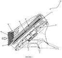
- FIGURE 1 a schematic representation of a heat exchanger module 100 configured with a protective grid system in accordance with an embodiment of the present invention is illustrated.
- the heat exchanger module 100 includes housing 10, an air inlet duct 40, at least one fan device 50 and a grid 60.
- the housing 10 receives therein at least one heat exchanger cores 20, 30.
- the housing 10 receives therein different heat exchanger cores that are disposed in series, wherein each heat exchanger core is preferably either one of a condenser, a radiator, a charge-air cooler and a chiller.
- each heat exchanger core is preferably either one of a condenser, a radiator, a charge-air cooler and a chiller.
- the sequence in which the radiator, condenser and chillers are disposed may vary, for example, the position of the radiator 20 and the condenser 30 may interchange based on design, packaging and other constrains, for example, the radiator can be disposed at the front to first receive the ram air and alternatively the condenser can be disposed at the front to first receive the ram air.
- the housing 10 is so configured to support the heat exchanger cores 20, 30 that the ram air either impinges either one of the heat exchanger cores 20, 30 either orthogonally or at some inclination
- the air inlet duct 40 is configured over the housing 10 and covers at least a portion of a surface of the at least one heat exchanger core 20, 30 and configures an opening 42.
- the air inlet duct 40 includes engagement elements 44 and 44' configured along at least one portion of at least one of the opposite longitudinal edges and at least one portion of at least one of the opposite lateral edges thereof respectively.
- the at least one fan device 50 is received within the housing 10.
- the at least one fan device 50 is disposed downstream of the at least one heat exchanger core 20, 30 that in turn is disposed within the housing 10.
- the fan device 50 generates pressure difference across the at least one heat exchanger core 20, 30 for facilitating flow of fluid there through.
- the present invention is not limited to any particular configuration and position of the at least one fan device 50 as far as the at least one fan device 50 is able to generate pressure difference across the at least one heat exchanger core 20, 30 for facilitating flow of fluid/ ram air there through.
- the grid 60 includes an array of elements defining restricted air flow passages 64, also simply referred to as air passages 64 that restrain passage of articles of a predetermined size but facilitates air flow there through.
- the elements are an array of horizontally and vertically disposed beams 62 that cross each other to configure the restricted air flow passages 64.
- FIGURE 2 illustrates an isometric view of the heat exchanger module 100 along with a schematic representation of the grid 60 and an enlarged view of the grid depicting inclination of the beams 62 configuring the grid 60.
- the beams 62 are so configured, spaced and oriented with respect to each other that the beams 62 direct and distribute ram air impinging on the grid 60 over the entire or maximum surface of the at least one heat exchanger core 20, 30 covered by the air inlet duct 40, thereby resulting in better utilization of the ram air for cooling the at least one heat exchanger cores 20, 30 and improving efficiency and performance of the heat exchanger.
- the beams 62 configured on the grid 60 in conjunction with the internal profile of the air inlet duct 40 directs and distributes the ram air impinging on the grid 60 over entire or maximum portion of the surface of the at least one heat exchanger core 20, 30 covered by the air inlet duct 40.
- the orientation of the beams 62 configuring the grid 60 varies from one section to another section of the grid 60.
- the orientation of the beams 62 formed an angle included between 2 and 45° with the plane XY, represented by main datum system XYZ in FIGURE 2 .
- the plane XY is defined as a plane parallel along the breadth or width of the grid 60 and is also perpendicular to the longitudinal axis Z.
- the configuration of the beams 62 configuring the grid 60 varies from one section to another section of the grid 60.
- any modification may be configured in the beams 62, to enable the beams 62 direct and distribute air impinging on the grid 60 over the entire or maximum surface of the at least one heat exchanger core 20, 30 covered by the air inlet duct 40.
- the ram air is directed and distributed over either entire or maximum surface of the at least one heat exchanger core 20, 30, thereby resulting in better utilization of the ram air for cooling the at least one heat exchanger cores 20, 30 and improving efficiency and performance of the heat exchanger.
- the elements are honeycomb structures that configure the restricted air passages.
- Such configuration of the grid 60 protects the at least one heat exchanger core 20, 30 against damage from impact of heavier articles such as stones and gravel, while still not compromising air flow through the at least one heat exchanger core 20, 30. Also such configuration of the grid 60 prevents lighter articles such as paper, polythene bags and leaves from getting in to path of ram air approaching the at least one heat exchanger core 20, 30, while still not compromising air flow through the heat exchanger core 20, 30. Such configuration of the grid 60 enhances service life of the heat exchanger and reduces maintenance thereof.
- the grid 60 is of metal and is configured by stamping process.
- the grid 60 is of plastic material and is configured by molding process with the beams or honeycomb structures integrally configured thereon during single step molding process.
- the grid 60 of the present invention is not limited to any particular configuration of the elements configuring the grid 60 and any particular material or process used for configuring the grid 60 as far as the grid 60 directs and distributes the ram air over entire or maximum surface of the heat exchanger core 20, 30 for better utilization of the ram air for cooling the heat exchanger and improving efficiency and performance of the heat exchanger.
- the grid 60 also acts as a barrier for preventing heavier articles such as stones and gravel from striking and damaging the at least one heat exchanger core 20, 30 and lighter articles such as paper, polythene bags and leaves from getting in to path of ram air approaching the at least one heat exchanger core 20, 30 while still not compromising air flow through the at least one heat exchanger core 20, 30.
- the grid 60 is mounted in spaced apart configuration and at an inclination relative to the at least one heat exchanger core 20, 30 to meet certain design requirements.
- the grid 60 is configured with at least one first engagement elements 66 and 66' configured along at least a portion of at least one of the opposite longitudinal edges and at least one portion of at least one of the opposite lateral edges of the grid 60 respectively that engage with corresponding complementary second engagement elements 44 and 44' configured along at least a portion of at least one of the opposite longitudinal edges and at least a portion of at least one of the opposite lateral edges of the air inlet duct 40 respectively.
- the grid 60 along with the engagement elements 66 and 66' configured on the grid 60 and the corresponding engagement elements 44 and 44' configured on the air inlet duct 40 collectively configures a protective grid system that can be easily retrofitted over current heat exchanger modules without requiring many modifications.
- FIGURE 3a to FIGURE 4b of the accompanying drawings depicting the engagement between the first engagement elements 66 and 66' and the corresponding complementary second engagement elements 44 and 44' for configuring detachable mounting of the grid 60 over the opening 42 configured by the air inlet duct 40.
- FIGURE 3a illustrates a schematic representation of the grid 60 with the first engagement elements 66 configured along at least a portion of a longitudinal edge thereof in a disengaged configuration with respect to corresponding complementary second engagement elements 44 configured along at least a portion of a corresponding longitudinal edge of the air inlet duct 40.
- FIGURE 3b illustrates a schematic representation of the grid 60 with the first engagement elements 66 thereof in an engaged configuration with respect to the complementary second engagement elements 44.
- FIGURE 4a illustrates a schematic representation of the grid 60 with a first engagement element 66' configured on a lateral edge of the grid 60 in a disengaged configuration with respect to a complementary second engagement element 44' configured on a corresponding lateral edge of the air inlet duct 40.
- FIGURE 4b illustrates a schematic representation of the grid 60 with the first engagement elements 66' thereof in an engaged configuration with respect to the complementary second engagement elements 44'.
- the engagement elements 66 and 66' are either one of clips, screws and expansion pins.
- the engagement elements 66 and 66' are snap fitting engagement elements.
- the grid 60 is received in sockets configured around a collar of the air inlet duct 40.
- the present invention is not limited to any particular configuration and placement of the engagement elements 66 and 66' as far as these elements configure detachable engagement between the grid 60 and the air inlet duct 40.
- the grid 60 is integrally formed over the opening 42 of the air inlet duct 40.
- the protective grid system as defined above, as long as it comprises housing, an air inlet duct, at least one fan device and a grid.
- the housing receives therein at least one heat exchanger core.
- the air inlet duct configured over the housing covers at least a portion of a surface of the at least one heat exchanger core and configures an opening.
- the at least one fan device is received within the housing generates pressure difference across the at least one heat exchanger core for facilitating flow of fluid there through.
- the grid is mounted over the opening of the air inlet duct and includes an array of beams that configures restricted passages. The beams are so configured, spaced and oriented with respect to each other that the beams direct and distribute fluid impinging thereon over the surface of the at least one heat exchanger core covered by the air inlet duct.
Landscapes
- Engineering & Computer Science (AREA)
- Mechanical Engineering (AREA)
- General Engineering & Computer Science (AREA)
- Physics & Mathematics (AREA)
- Thermal Sciences (AREA)
- Chemical & Material Sciences (AREA)
- Combustion & Propulsion (AREA)
- Transportation (AREA)
- Heat-Exchange Devices With Radiators And Conduit Assemblies (AREA)
- Details Of Heat-Exchange And Heat-Transfer (AREA)
Abstract
Description
- The present disclosure relates to a heat exchanger module for a vehicle. Particularly, the present disclosure relates to a heat exchanger module configured with a protective grid system for protecting elements thereof and directing and distributing air over a heat exchanger core.
- A vehicle includes several heat exchanger elements. For example, a conventional engine cooling system of a vehicle includes a heat exchanger in form of a radiator to facilitate cooling of an engine of the vehicle. Specifically, a coolant in form of glycol or water-glycol mixture is passed through the engine, from where the coolant absorbs heat and becomes hot. The hot coolant is then fed into an inlet tank of the radiator that is located preferably on top of the radiator, or along one side of the radiator, from the inlet tank the hot coolant is distributed across a radiator core through radiator tubes to another tank on an opposite end of the radiator. As the hot coolant passes through the radiator tubes to the opposite tank, the coolant transfers heat to tubes of the radiator core, which in turn, transfers the heat to fins that are lodged between each row of radiator tubes. The fins then release the heat to the ambient air that flows across the radiator core. For effective and efficient performance of the radiator, there should be unhindered supply of ambient air to the radiator core. In order to save the power consumption in the vehicle, natural draft of air across the radiator core is utilized. For achieving natural draft of air across the radiator core, the radiator core is disposed behind a front grill of the vehicle, wherein the front grill is disposed between a front hood and a front bumper of the vehicle such that the ram air impinges on the front grille of the vehicle as the vehicle moves ahead in forward direction. Such strategic placement of the radiator core enables the ram air to directly impinge on and pass through the radiator core, thereby creating natural draft of air across the radiator core as the vehicle moves ahead in the forward direction. The engine cooling system often incorporates one or more fan elements disposed preferably behind the radiator core to generate a forced draft of air that facilities passage of air through the radiator core. The forced draft generated by the fan elements improves the performance and efficiency of the radiator by improving the air flow rate through the radiator by increasing the air speed. The radiator may be disposed either alone or in series with other heat exchange elements such as for example, a condenser and a chiller that also requires draft of air for efficient operation thereof. Also, the sequence in which the radiator, condenser and chillers are disposed may vary and the position of the radiator and the condenser can interchange, for example, the radiator can be disposed at the front to first receive the ram air and alternatively the condenser can be disposed at the front to first receive the ram air.
- However, when the vehicle is travelling in off-road conditions or over a rough terrain, heavier articles such as stones, gravel, and the likes may approach the vehicle, cross the front grill and strike a front face of the heat exchanger core, such as for example, radiator core or condenser core. As a result, the heavier article may cause damage to, particularly, may cause cracks in the heat exchange tubes carrying heat exchange fluid there through. The cracks may cause leakage of the tubes. The continuous leakage of the heat exchange fluid from the heat exchange tubes may result in problems such as pressure loss inside the heat exchanger tubes, heat exchanger tank requiring frequent refilling and inefficient operation of the heat exchanger due to insufficient heat exchange fluid. Conditions such as dropping of heat exchange fluid levels in the heat exchanger, for example radiator below critical level may render the radiator inefficient, thereby resulting in engine seizure due to excessive heat. The cracks may also act as points of stress concentration, thereby may cause mechanical failure. In case the heavier articles strike the delicate fin elements disposed between adjacent tubular elements, the fin elements may get damaged and not function as per design, thereby deteriorating efficiency and performance of the heat exchanger. Also, the high speed ram air often carries therewith lighter articles such as paper, empty polythene bags, leaves and the likes, that may reach the front face of the heat exchanger core and may get struck over there due to draft of air created by the at least one fan element or the ram air. Most often, these lighter articles accumulate in the space behind the front grille and in front of the heat exchanger core, thereby causing hindrance to air flow and preventing ram air from reaching and entering the heat exchanger core, thereby deteriorating efficiency and performance of the heat exchanger.
- Certain prior art suggest placing a grid over the front face of the heat exchanger core to prevent heavier articles from impacting the heat exchanger core and prevent lighter articles from accumulating in front of the heat exchanger core. In some cases the grid is disposed spaced from the radiator or the condenser core. Such arrangement facilitates in dissipating energy of the heavier article as the heavier article travels through space between the front grille and the radiator core. Also, depending upon the configuration of the housing receiving the heat exchanger core, the heat exchanger core may be either disposed orthogonally or at an inclination with respect to direction of the ram air. Considering such design limitations, the ram air often fails to cover majority of the surface of the heat exchanger core, thereby limiting utilization of ram air for cooling of the heat exchanger core.
- Accordingly, there is a need for a heat exchanger module configured with a protective grid system that not only protects the heat exchanger core such as radiator and/or condenser core but also directs and distributes the ram air over maximum surface of the heat exchanger core, thereby resulting in better utilization of the ram air for cooling the heat exchanger and improving the performance and efficiency of the heat exchanger. Further, there is a need for a heat exchanger module configured with a protective grid system that acts as a barrier in front of the radiator or condenser core and prevents heavier articles such as stones from impacting and damaging the radiator and/or condenser core, while still not compromising air flow through the radiator or condenser core. Also, there is a need for a heat exchanger module configured with a protective grid system that prevents lighter articles such as paper, polythene bags and leaves from getting in to path of ram air approaching the radiator or condenser core and deteriorating efficiency and performance of the radiator or condenser respectively, while still not comprising air flow through the radiator or condenser core.
- An object of the present invention is to provide a heat exchanger module configured with a protective grid system that not only protects a heat exchanger core but also directs and distributes the ram air over maximum surface of the heat exchanger core.
- Another object of the present invention is to provide a heat exchanger module configured with a protective grid system that achieves better utilization of the ram air for cooling a heat exchanger, thereby improving efficiency and performance of the heat exchanger.
- Still another object of the present invention is to provide a heat exchanger module configured with a protective grid system that protects a heat exchanger core against damage from impact of heavier articles such as stones and gravel, while still not compromising air flow through the heat exchanger core.
- Yet another object of the present invention is to provide a heat exchanger module configured with a protective grid system that prevents lighter articles such as paper, polythene bags and leaves from getting in to path of ram air approaching a heat exchanger core, while still not compromising air flow through the heat exchanger core.
- Still another object of the present invention is to provide a heat exchanger module configured with a protective grid system that can be easily retrofitted over current heat exchangers without requiring many modifications.
- Another object of the present invention is to provide a heat exchanger module configured with a protective grid system that enhances service life of a heat exchanger and reduces maintenance thereof.
- Yet another of the present invention is to provide a heat exchanger module configured with a protective grid system that is inexpensive and also convenient to manufacture, assemble and use.
- In the present description, some elements or parameters may be indexed, such as a first element and a second element. In this case, unless stated otherwise, this indexation is only meant to differentiate and name elements which are similar but not identical. No idea of priority should be inferred from such indexation, as these terms may be switched without betraying the invention. Additionally, this indexation does not imply any order in mounting or use of the elements of the invention.
- In accordance with an embodiment of the invention, a heat exchanger module is disclosed. The heat exchanger module includes housing, an air inlet duct, at least one fan device and a grid. The housing receives therein at least one heat exchanger core. The air inlet duct configured over the housing covers at least a portion of a surface of the at least one heat exchanger core and configures an opening. The at least one fan device is received within the housing. The fan device generates pressure difference across the at least one heat exchanger core for facilitating flow of fluid there through. The grid is mounted over the opening of the air inlet duct such that the grid is spaced from the at least one heat exchanger core. The grid includes an array of beams that configures restricted passages. The beams are so configured, spaced and oriented with respect to each other that the beams direct and distribute fluid impinging on said grid over the surface of the at least one heat exchanger core covered by the air inlet duct.
- Generally, the housing receives therein different heat exchangers that are disposed in series, wherein each heat exchanger is preferably either one of condenser, radiator, charge-air cooler and chiller.
- In accordance with an embodiment of the present invention, the air inlet duct is so configured that internal profile of the air inlet duct in conjunction with the beams configured on the grid direct and distribute fluid impinging on the grid over entire portion of the surface of the at least one heat exchanger core covered by the air inlet duct.
- Further, the grid includes first engagement elements configured thereon that engages with complimentary second engagement elements configured on the air inlet duct for facilitating detachable mounting of the grid over the opening of the air inlet duct.
- In accordance with an embodiment of the present invention, the engagement elements are either one of clips, screws and expansion pins.
- Generally, the orientation of the beams configuring the grid varies from one section to another section of the grid.
- Particularly, the orientation of the beams formed an angle included between 2 and 45° with the transversal axis of the grid.
- In accordance with an embodiment of the present invention, configuration of the beams configuring the grid varies from one section to another section of the grid.
- In accordance with an embodiment of the present invention, the grid is of metal and is configured by stamping process.
- Alternatively, the grid is of composite plastic material and is configured by molding process.
- Generally, the grid is received in sockets configured around a collar of the air inlet duct.
- Other characteristics, details and advantages of the invention can be inferred from the description of the invention hereunder. A more complete appreciation of the invention and many of the attendant advantages thereof will be readily obtained as the same becomes better understood by reference to the following detailed description when considered in connection with the accompanying figures, wherein:
-
FIGURE 1 illustrates a schematic representation of a heat exchanger module in accordance with an embodiment of the present invention, wherein a grid of a protective grid system is mounted in spaced apart configuration and at an inclination relative to a heat exchanger core of the heat exchanger module; -
FIGURE 2 illustrates an isometric view of the heat exchanger module ofFIGURE 1 , also is depicted schematic representation of the grid and an enlarged view of the grid depicting inclination of beams configuring the grid; -
FIGURE 3a illustrates a schematic representation of the grid ofFIGURE 1 with first engagement elements configured along at least a portion of a longitudinal edge of the grid in a disengaged configuration with respect to complementary second engagement elements configured on at least a portion of a corresponding longitudinal edge of an air inlet duct in accordance with an embodiment of the present invention; -
FIGURE 3b illustrates a schematic representation of the grid with the first engagement elements thereof in an engaged configuration with respect to the complementary second engagement elements ofFIGURE 3a ; -
FIGURE 4a illustrates a schematic representation of the grid ofFIGURE 1 with a first engagement element configured along a lateral edge of the grid in a disengaged configuration with respect to a complementary second engagement element configured on a corresponding lateral edge of an air inlet duct; and -
FIGURE 4b illustrates a schematic representation of the grid with the first engagement element thereof in an engaged configuration with respect to the complementary second engagement element ofFIGURE 4a . - The present invention envisages a heat exchanger module configured with a protective grid system that includes at least one grid mounted in a spaced apart configuration and at an inclination with respect to at least one heat exchanger core, such as for example, a radiator core and/or condenser core. The beams configuring the grid not only protects the heat exchanger core but also directs and distributes the ram air over maximum surface of the heat exchanger core, thereby achieving proper utilization of the ram air for improving efficiency and performance of the heat exchanger. Although, the protective grid system of the present invention is used in heat exchangers, such as radiators, condensers and evaporators that are used in vehicles, however, the protective grid system of the present invention is also applicable to any other heat exchangers used in non-vehicular systems such as generators that also involve air draft for achieving better performance of the heat exchanger.
- Referring to
FIGURE 1 , a schematic representation of aheat exchanger module 100 configured with a protective grid system in accordance with an embodiment of the present invention is illustrated. Theheat exchanger module 100 includeshousing 10, anair inlet duct 40, at least onefan device 50 and agrid 60. - The
housing 10 receives therein at least oneheat exchanger cores housing 10 receives therein different heat exchanger cores that are disposed in series, wherein each heat exchanger core is preferably either one of a condenser, a radiator, a charge-air cooler and a chiller. Also, the sequence in which the radiator, condenser and chillers are disposed may vary, for example, the position of theradiator 20 and thecondenser 30 may interchange based on design, packaging and other constrains, for example, the radiator can be disposed at the front to first receive the ram air and alternatively the condenser can be disposed at the front to first receive the ram air. Thehousing 10 is so configured to support theheat exchanger cores heat exchanger cores - The
air inlet duct 40 is configured over thehousing 10 and covers at least a portion of a surface of the at least oneheat exchanger core opening 42. Theair inlet duct 40 includesengagement elements 44 and 44' configured along at least one portion of at least one of the opposite longitudinal edges and at least one portion of at least one of the opposite lateral edges thereof respectively. - The at least one
fan device 50 is received within thehousing 10. Preferably, the at least onefan device 50 is disposed downstream of the at least oneheat exchanger core housing 10. Thefan device 50 generates pressure difference across the at least oneheat exchanger core fan device 50 as far as the at least onefan device 50 is able to generate pressure difference across the at least oneheat exchanger core - In accordance with an embodiment, the
grid 60 includes an array of elements defining restrictedair flow passages 64, also simply referred to asair passages 64 that restrain passage of articles of a predetermined size but facilitates air flow there through. In accordance with a preferred embodiment, the elements are an array of horizontally and vertically disposedbeams 62 that cross each other to configure the restrictedair flow passages 64.FIGURE 2 illustrates an isometric view of theheat exchanger module 100 along with a schematic representation of thegrid 60 and an enlarged view of the grid depicting inclination of thebeams 62 configuring thegrid 60. Thebeams 62 are so configured, spaced and oriented with respect to each other that thebeams 62 direct and distribute ram air impinging on thegrid 60 over the entire or maximum surface of the at least oneheat exchanger core air inlet duct 40, thereby resulting in better utilization of the ram air for cooling the at least oneheat exchanger cores beams 62 configured on thegrid 60 in conjunction with the internal profile of theair inlet duct 40 directs and distributes the ram air impinging on thegrid 60 over entire or maximum portion of the surface of the at least oneheat exchanger core air inlet duct 40. In accordance with an embodiment of the present invention, the orientation of thebeams 62 configuring thegrid 60 varies from one section to another section of thegrid 60. In accordance with an embodiment, the orientation of thebeams 62 formed an angle included between 2 and 45° with the plane XY, represented by main datum system XYZ inFIGURE 2 . The plane XY is defined as a plane parallel along the breadth or width of thegrid 60 and is also perpendicular to the longitudinal axis Z. In accordance with still another embodiment of the present invention, the configuration of thebeams 62 configuring thegrid 60 varies from one section to another section of thegrid 60. Any modification may be configured in thebeams 62, to enable thebeams 62 direct and distribute air impinging on thegrid 60 over the entire or maximum surface of the at least oneheat exchanger core air inlet duct 40. With such configuration of thegrid 60 and theair inlet duct 40, the ram air is directed and distributed over either entire or maximum surface of the at least oneheat exchanger core heat exchanger cores grid 60 protects the at least oneheat exchanger core heat exchanger core grid 60 prevents lighter articles such as paper, polythene bags and leaves from getting in to path of ram air approaching the at least oneheat exchanger core heat exchanger core grid 60 enhances service life of the heat exchanger and reduces maintenance thereof. - In accordance with an embodiment, the
grid 60 is of metal and is configured by stamping process. In accordance with another embodiment, thegrid 60 is of plastic material and is configured by molding process with the beams or honeycomb structures integrally configured thereon during single step molding process. However, thegrid 60 of the present invention is not limited to any particular configuration of the elements configuring thegrid 60 and any particular material or process used for configuring thegrid 60 as far as thegrid 60 directs and distributes the ram air over entire or maximum surface of theheat exchanger core grid 60 also acts as a barrier for preventing heavier articles such as stones and gravel from striking and damaging the at least oneheat exchanger core heat exchanger core heat exchanger core - Again referring to
FIGURE 1 , thegrid 60 is mounted in spaced apart configuration and at an inclination relative to the at least oneheat exchanger core grid 60 is configured with at least onefirst engagement elements 66 and 66' configured along at least a portion of at least one of the opposite longitudinal edges and at least one portion of at least one of the opposite lateral edges of thegrid 60 respectively that engage with corresponding complementarysecond engagement elements 44 and 44' configured along at least a portion of at least one of the opposite longitudinal edges and at least a portion of at least one of the opposite lateral edges of theair inlet duct 40 respectively. Thegrid 60 along with theengagement elements 66 and 66' configured on thegrid 60 and thecorresponding engagement elements 44 and 44' configured on theair inlet duct 40 collectively configures a protective grid system that can be easily retrofitted over current heat exchanger modules without requiring many modifications. Refer toFIGURE 3a to FIGURE 4b of the accompanying drawings depicting the engagement between thefirst engagement elements 66 and 66' and the corresponding complementarysecond engagement elements 44 and 44' for configuring detachable mounting of thegrid 60 over theopening 42 configured by theair inlet duct 40. More specifically, theFIGURE 3a illustrates a schematic representation of thegrid 60 with thefirst engagement elements 66 configured along at least a portion of a longitudinal edge thereof in a disengaged configuration with respect to corresponding complementarysecond engagement elements 44 configured along at least a portion of a corresponding longitudinal edge of theair inlet duct 40.FIGURE 3b illustrates a schematic representation of thegrid 60 with thefirst engagement elements 66 thereof in an engaged configuration with respect to the complementarysecond engagement elements 44.FIGURE 4a illustrates a schematic representation of thegrid 60 with a first engagement element 66' configured on a lateral edge of thegrid 60 in a disengaged configuration with respect to a complementary second engagement element 44' configured on a corresponding lateral edge of theair inlet duct 40.FIGURE 4b illustrates a schematic representation of thegrid 60 with the first engagement elements 66' thereof in an engaged configuration with respect to the complementary second engagement elements 44'. In accordance with an embodiment of the present invention theengagement elements 66 and 66' are either one of clips, screws and expansion pins. In accordance with an embodiment of the present invention theengagement elements 66 and 66' are snap fitting engagement elements. In accordance with still another embodiment, thegrid 60 is received in sockets configured around a collar of theair inlet duct 40. However, the present invention is not limited to any particular configuration and placement of theengagement elements 66 and 66' as far as these elements configure detachable engagement between thegrid 60 and theair inlet duct 40. In accordance with another embodiment of the present invention, thegrid 60 is integrally formed over the opening 42 of theair inlet duct 40. - Several modifications and improvement might be applied by the person skilled in the art to the protective grid system as defined above, as long as it comprises housing, an air inlet duct, at least one fan device and a grid. The housing receives therein at least one heat exchanger core. The air inlet duct configured over the housing covers at least a portion of a surface of the at least one heat exchanger core and configures an opening. The at least one fan device is received within the housing generates pressure difference across the at least one heat exchanger core for facilitating flow of fluid there through. The grid is mounted over the opening of the air inlet duct and includes an array of beams that configures restricted passages. The beams are so configured, spaced and oriented with respect to each other that the beams direct and distribute fluid impinging thereon over the surface of the at least one heat exchanger core covered by the air inlet duct.
- In any case, the invention cannot and should not be limited to the embodiments specifically described in this document, as other embodiments might exist. The invention shall spread to any equivalent means and any technically operating combination of means.
Claims (11)
- A heat exchanger module (100) comprising:• a housing (10) adapted to receive therein at least one heat exchanger core (20, 30);• an air inlet duct (40) configured over said housing (10) and adapted to cover at least a portion of a surface of said at least one heat exchanger core (20, 30) and configure an opening (42);• at least one fan device (50) received within said housing (10) and adapted to generate pressure difference across said at least one heat exchanger core (20, 30) for facilitating flow of fluid there through;• a grid (60) adapted to be mounted over said opening (42) of said air inlet duct (40) such that said grid (60) is spaced from said at least one heat exchanger core (20, 30), said grid (60) comprising an array of beams (62) adapted to configure restricted passages (64), said beams (62) are so configured, spaced and oriented with respect to each other that said beams (62) are adapted to direct and distribute fluid impinging on said grid (60) over said surface of said at least one heat exchanger core (20, 30) covered by said air inlet duct (40).
- The heat exchanger module (100) as claimed in the preceding claim, wherein said housing (10) is adapted to receive therein different heat exchangers that are disposed in series, each heat exchanger is preferably either one of condenser, radiator, charge-air cooler and chiller.
- The heat exchanger module (100) as claimed in any of the preceding claims, wherein said air inlet duct (40) is so configured that internal profile of said air inlet duct (40) in conjunction with said beams (62) configured on said grid (60) are adapted to direct and distribute fluid impinging on said grid (60) over entire portion of said surface of said at least one heat exchanger core (20, 30) covered by said air inlet duct (40).
- The heat exchanger module (100) as claimed in any of the preceding claims, wherein said grid (60) further comprises first engagement elements (66, 66') configured thereon and adapted to engage with complimentary second engagement elements (44, 44') configured on said air inlet duct (40) for facilitating detachable mounting of said grid (60) over said opening (42) of said air inlet duct (40).
- The heat exchanger module (100) as claimed in the preceding claim, wherein said engagement elements are either one of clips, screws and expansion pins.
- The heat exchanger module (100) as claimed in any of the preceding claims, wherein orientation of said beams (62) configuring said grid (60) vary from one section to another section of said grid (60).
- The heat exchanger module (100) as claimed in the preceding claim, wherein said orientation of said beams (62) formed an angle comprised between 2 and 45° with the transversal axis of said grid (60).
- The heat exchanger module (100) as claimed in any of the preceding claims, wherein configuration of said beams (62) configuring said grid (60) vary from one section to another section of said grid (60).
- The heat exchanger module (100) as claimed in any of the preceding claims, wherein said grid (60) is of metal and is configured by stamping process.
- The heat exchanger module (100) as claimed in any of claims 1 to 7, wherein said grid (60) is of composite plastic material and is configured by molding process.
- The heat exchanger module (100) as claimed in any of the preceding claims, wherein said grid (60) is received in sockets configured around a collar of said air inlet duct (40).
Priority Applications (1)
| Application Number | Priority Date | Filing Date | Title |
|---|---|---|---|
| EP18181389.0A EP3591328B1 (en) | 2018-07-03 | 2018-07-03 | A heat exchanger module with protective grid for directing and distributing air |
Applications Claiming Priority (1)
| Application Number | Priority Date | Filing Date | Title |
|---|---|---|---|
| EP18181389.0A EP3591328B1 (en) | 2018-07-03 | 2018-07-03 | A heat exchanger module with protective grid for directing and distributing air |
Publications (2)
| Publication Number | Publication Date |
|---|---|
| EP3591328A1 true EP3591328A1 (en) | 2020-01-08 |
| EP3591328B1 EP3591328B1 (en) | 2022-08-17 |
Family
ID=62846039
Family Applications (1)
| Application Number | Title | Priority Date | Filing Date |
|---|---|---|---|
| EP18181389.0A Active EP3591328B1 (en) | 2018-07-03 | 2018-07-03 | A heat exchanger module with protective grid for directing and distributing air |
Country Status (1)
| Country | Link |
|---|---|
| EP (1) | EP3591328B1 (en) |
Cited By (4)
| Publication number | Priority date | Publication date | Assignee | Title |
|---|---|---|---|---|
| EP4169755A1 (en) * | 2021-10-19 | 2023-04-26 | Audi AG | Radiator arrangement for a vehicle and vehicle |
| EP4417929A1 (en) * | 2023-02-16 | 2024-08-21 | The Boeing Company | Modular heat exchanger systems |
| WO2025038340A1 (en) * | 2023-08-15 | 2025-02-20 | Valeo Systemes Thermiques | Stone guard |
| FR3161263A1 (en) * | 2024-04-15 | 2025-10-17 | Valeo Systemes Thermiques | Set comprising an air intake duct and a protective grille |
Citations (5)
| Publication number | Priority date | Publication date | Assignee | Title |
|---|---|---|---|---|
| US20110114286A1 (en) * | 2008-12-05 | 2011-05-19 | Mitsubishi Heavy Industries, Ltd. | Vehicle heat-exchange module and vehicle having the same |
| US20120085510A1 (en) * | 2010-10-06 | 2012-04-12 | Kia Motors Corporation | Cooling apparatus for vehicle |
| US20120241128A1 (en) * | 2009-09-29 | 2012-09-27 | Vacca Frederic | Heat Exchange Block For A Motor Vehicle |
| US20130052000A1 (en) * | 2011-08-29 | 2013-02-28 | Cheng Ming Su | Structure of wind direction cover of electric fan |
| WO2016177826A1 (en) * | 2015-05-06 | 2016-11-10 | Valeo Systemes Thermiques | Protective device for heat exchangers |
-
2018
- 2018-07-03 EP EP18181389.0A patent/EP3591328B1/en active Active
Patent Citations (5)
| Publication number | Priority date | Publication date | Assignee | Title |
|---|---|---|---|---|
| US20110114286A1 (en) * | 2008-12-05 | 2011-05-19 | Mitsubishi Heavy Industries, Ltd. | Vehicle heat-exchange module and vehicle having the same |
| US20120241128A1 (en) * | 2009-09-29 | 2012-09-27 | Vacca Frederic | Heat Exchange Block For A Motor Vehicle |
| US20120085510A1 (en) * | 2010-10-06 | 2012-04-12 | Kia Motors Corporation | Cooling apparatus for vehicle |
| US20130052000A1 (en) * | 2011-08-29 | 2013-02-28 | Cheng Ming Su | Structure of wind direction cover of electric fan |
| WO2016177826A1 (en) * | 2015-05-06 | 2016-11-10 | Valeo Systemes Thermiques | Protective device for heat exchangers |
Cited By (9)
| Publication number | Priority date | Publication date | Assignee | Title |
|---|---|---|---|---|
| EP4169755A1 (en) * | 2021-10-19 | 2023-04-26 | Audi AG | Radiator arrangement for a vehicle and vehicle |
| WO2023066571A1 (en) * | 2021-10-19 | 2023-04-27 | Audi Ag | Radiator arrangement for a vehicle and vehicle |
| US12611924B2 (en) | 2021-10-19 | 2026-04-28 | Audi Ag | Radiator arrangement for a vehicle and vehicle |
| EP4417929A1 (en) * | 2023-02-16 | 2024-08-21 | The Boeing Company | Modular heat exchanger systems |
| US20240278921A1 (en) * | 2023-02-16 | 2024-08-22 | The Boeing Company | Modular heat exchanger systems |
| US12434845B2 (en) | 2023-02-16 | 2025-10-07 | The Boeing Company | Modular heat exchanger systems |
| WO2025038340A1 (en) * | 2023-08-15 | 2025-02-20 | Valeo Systemes Thermiques | Stone guard |
| FR3161263A1 (en) * | 2024-04-15 | 2025-10-17 | Valeo Systemes Thermiques | Set comprising an air intake duct and a protective grille |
| WO2025219287A1 (en) * | 2024-04-15 | 2025-10-23 | Valeo Systemes Thermiques | Assembly comprising an air intake duct and a protective grille |
Also Published As
| Publication number | Publication date |
|---|---|
| EP3591328B1 (en) | 2022-08-17 |
Similar Documents
| Publication | Publication Date | Title |
|---|---|---|
| EP3591328B1 (en) | A heat exchanger module with protective grid for directing and distributing air | |
| CA2429872C (en) | Heat exchanger package | |
| KR101405234B1 (en) | Radiator for vehicle | |
| JP2005053464A (en) | Vehicle front end structure | |
| JP2005035476A (en) | Vehicle cooling system | |
| US20190128171A1 (en) | Cooling structure for vehicle | |
| US3770049A (en) | Vehicle cooling system | |
| KR101646129B1 (en) | Radiator for vehicle | |
| KR20170079203A (en) | Cooling module for vehicle | |
| KR20110063117A (en) | Car Cooling System | |
| EP3671099A1 (en) | A protection grid for a heat exchanger module | |
| EP3457071B1 (en) | A protection device for a heat exchanger | |
| EP3590771B1 (en) | A protective grid system with sealing elements | |
| EP3943865A1 (en) | A heat exchanger assembly | |
| JP4506413B2 (en) | Fuel cell vehicle cooling system | |
| JP4415712B2 (en) | Heat exchanger | |
| JP2018017194A (en) | Attachment structure of intercooler | |
| US20220252362A1 (en) | A protection system for a heat exchanger | |
| US20190024573A1 (en) | Cooling Module | |
| JP3630201B2 (en) | Integrated heat exchanger | |
| EP3770024B1 (en) | A protection system for a heat exchanger | |
| US10492342B2 (en) | System for cooling an electronic device and assembly method | |
| US12043105B2 (en) | Cooling assembly for a motor vehicle | |
| KR102602089B1 (en) | Cooling System of Fuel Cell Vehicle | |
| CN113085473B (en) | Layout structure of refrigerant piping near heat accumulator in vehicle |
Legal Events
| Date | Code | Title | Description |
|---|---|---|---|
| PUAI | Public reference made under article 153(3) epc to a published international application that has entered the european phase |
Free format text: ORIGINAL CODE: 0009012 |
|
| STAA | Information on the status of an ep patent application or granted ep patent |
Free format text: STATUS: THE APPLICATION HAS BEEN PUBLISHED |
|
| AK | Designated contracting states |
Kind code of ref document: A1 Designated state(s): AL AT BE BG CH CY CZ DE DK EE ES FI FR GB GR HR HU IE IS IT LI LT LU LV MC MK MT NL NO PL PT RO RS SE SI SK SM TR |
|
| AX | Request for extension of the european patent |
Extension state: BA ME |
|
| STAA | Information on the status of an ep patent application or granted ep patent |
Free format text: STATUS: REQUEST FOR EXAMINATION WAS MADE |
|
| 17P | Request for examination filed |
Effective date: 20200708 |
|
| RBV | Designated contracting states (corrected) |
Designated state(s): AL AT BE BG CH CY CZ DE DK EE ES FI FR GB GR HR HU IE IS IT LI LT LU LV MC MK MT NL NO PL PT RO RS SE SI SK SM TR |
|
| GRAP | Despatch of communication of intention to grant a patent |
Free format text: ORIGINAL CODE: EPIDOSNIGR1 |
|
| STAA | Information on the status of an ep patent application or granted ep patent |
Free format text: STATUS: GRANT OF PATENT IS INTENDED |
|
| RIC1 | Information provided on ipc code assigned before grant |
Ipc: F01P 11/10 20060101ALI20220204BHEP Ipc: F01P 3/18 20060101ALI20220204BHEP Ipc: B60K 11/08 20060101ALI20220204BHEP Ipc: B60K 11/04 20060101ALI20220204BHEP Ipc: F28F 19/00 20060101ALI20220204BHEP Ipc: F28D 1/02 20060101ALI20220204BHEP Ipc: F28D 21/00 20060101ALI20220204BHEP Ipc: F28D 7/16 20060101ALI20220204BHEP Ipc: F28D 1/04 20060101ALI20220204BHEP Ipc: F28F 13/06 20060101ALI20220204BHEP Ipc: F28F 9/02 20060101AFI20220204BHEP |
|
| RAP3 | Party data changed (applicant data changed or rights of an application transferred) |
Owner name: VALEO AUTOSYSTEMY SP. Z O.O. |
|
| INTG | Intention to grant announced |
Effective date: 20220307 |
|
| RIN1 | Information on inventor provided before grant (corrected) |
Inventor name: BRANKIEWICZ, KRYSZTOF Inventor name: WATOR, TOMASZ Inventor name: BARUS, LUKASZ Inventor name: GODZINA, RADOSLAW |
|
| GRAS | Grant fee paid |
Free format text: ORIGINAL CODE: EPIDOSNIGR3 |
|
| GRAA | (expected) grant |
Free format text: ORIGINAL CODE: 0009210 |
|
| STAA | Information on the status of an ep patent application or granted ep patent |
Free format text: STATUS: THE PATENT HAS BEEN GRANTED |
|
| AK | Designated contracting states |
Kind code of ref document: B1 Designated state(s): AL AT BE BG CH CY CZ DE DK EE ES FI FR GB GR HR HU IE IS IT LI LT LU LV MC MK MT NL NO PL PT RO RS SE SI SK SM TR |
|
| REG | Reference to a national code |
Ref country code: CH Ref legal event code: EP |
|
| REG | Reference to a national code |
Ref country code: DE Ref legal event code: R096 Ref document number: 602018039324 Country of ref document: DE |
|
| REG | Reference to a national code |
Ref country code: IE Ref legal event code: FG4D |
|
| REG | Reference to a national code |
Ref country code: AT Ref legal event code: REF Ref document number: 1512445 Country of ref document: AT Kind code of ref document: T Effective date: 20220915 |
|
| REG | Reference to a national code |
Ref country code: NL Ref legal event code: MP Effective date: 20220817 |
|
| REG | Reference to a national code |
Ref country code: LT Ref legal event code: MG9D |
|
| PG25 | Lapsed in a contracting state [announced via postgrant information from national office to epo] |
Ref country code: SE Free format text: LAPSE BECAUSE OF FAILURE TO SUBMIT A TRANSLATION OF THE DESCRIPTION OR TO PAY THE FEE WITHIN THE PRESCRIBED TIME-LIMIT Effective date: 20220817 Ref country code: RS Free format text: LAPSE BECAUSE OF FAILURE TO SUBMIT A TRANSLATION OF THE DESCRIPTION OR TO PAY THE FEE WITHIN THE PRESCRIBED TIME-LIMIT Effective date: 20220817 Ref country code: PT Free format text: LAPSE BECAUSE OF FAILURE TO SUBMIT A TRANSLATION OF THE DESCRIPTION OR TO PAY THE FEE WITHIN THE PRESCRIBED TIME-LIMIT Effective date: 20221219 Ref country code: NO Free format text: LAPSE BECAUSE OF FAILURE TO SUBMIT A TRANSLATION OF THE DESCRIPTION OR TO PAY THE FEE WITHIN THE PRESCRIBED TIME-LIMIT Effective date: 20221117 Ref country code: NL Free format text: LAPSE BECAUSE OF FAILURE TO SUBMIT A TRANSLATION OF THE DESCRIPTION OR TO PAY THE FEE WITHIN THE PRESCRIBED TIME-LIMIT Effective date: 20220817 Ref country code: LV Free format text: LAPSE BECAUSE OF FAILURE TO SUBMIT A TRANSLATION OF THE DESCRIPTION OR TO PAY THE FEE WITHIN THE PRESCRIBED TIME-LIMIT Effective date: 20220817 Ref country code: LT Free format text: LAPSE BECAUSE OF FAILURE TO SUBMIT A TRANSLATION OF THE DESCRIPTION OR TO PAY THE FEE WITHIN THE PRESCRIBED TIME-LIMIT Effective date: 20220817 Ref country code: FI Free format text: LAPSE BECAUSE OF FAILURE TO SUBMIT A TRANSLATION OF THE DESCRIPTION OR TO PAY THE FEE WITHIN THE PRESCRIBED TIME-LIMIT Effective date: 20220817 |
|
| REG | Reference to a national code |
Ref country code: AT Ref legal event code: MK05 Ref document number: 1512445 Country of ref document: AT Kind code of ref document: T Effective date: 20220817 |
|
| PG25 | Lapsed in a contracting state [announced via postgrant information from national office to epo] |
Ref country code: PL Free format text: LAPSE BECAUSE OF FAILURE TO SUBMIT A TRANSLATION OF THE DESCRIPTION OR TO PAY THE FEE WITHIN THE PRESCRIBED TIME-LIMIT Effective date: 20220817 Ref country code: IS Free format text: LAPSE BECAUSE OF FAILURE TO SUBMIT A TRANSLATION OF THE DESCRIPTION OR TO PAY THE FEE WITHIN THE PRESCRIBED TIME-LIMIT Effective date: 20221217 Ref country code: HR Free format text: LAPSE BECAUSE OF FAILURE TO SUBMIT A TRANSLATION OF THE DESCRIPTION OR TO PAY THE FEE WITHIN THE PRESCRIBED TIME-LIMIT Effective date: 20220817 Ref country code: GR Free format text: LAPSE BECAUSE OF FAILURE TO SUBMIT A TRANSLATION OF THE DESCRIPTION OR TO PAY THE FEE WITHIN THE PRESCRIBED TIME-LIMIT Effective date: 20221118 |
|
| PG25 | Lapsed in a contracting state [announced via postgrant information from national office to epo] |
Ref country code: SM Free format text: LAPSE BECAUSE OF FAILURE TO SUBMIT A TRANSLATION OF THE DESCRIPTION OR TO PAY THE FEE WITHIN THE PRESCRIBED TIME-LIMIT Effective date: 20220817 Ref country code: RO Free format text: LAPSE BECAUSE OF FAILURE TO SUBMIT A TRANSLATION OF THE DESCRIPTION OR TO PAY THE FEE WITHIN THE PRESCRIBED TIME-LIMIT Effective date: 20220817 Ref country code: ES Free format text: LAPSE BECAUSE OF FAILURE TO SUBMIT A TRANSLATION OF THE DESCRIPTION OR TO PAY THE FEE WITHIN THE PRESCRIBED TIME-LIMIT Effective date: 20220817 Ref country code: DK Free format text: LAPSE BECAUSE OF FAILURE TO SUBMIT A TRANSLATION OF THE DESCRIPTION OR TO PAY THE FEE WITHIN THE PRESCRIBED TIME-LIMIT Effective date: 20220817 Ref country code: CZ Free format text: LAPSE BECAUSE OF FAILURE TO SUBMIT A TRANSLATION OF THE DESCRIPTION OR TO PAY THE FEE WITHIN THE PRESCRIBED TIME-LIMIT Effective date: 20220817 Ref country code: AT Free format text: LAPSE BECAUSE OF FAILURE TO SUBMIT A TRANSLATION OF THE DESCRIPTION OR TO PAY THE FEE WITHIN THE PRESCRIBED TIME-LIMIT Effective date: 20220817 |
|
| REG | Reference to a national code |
Ref country code: DE Ref legal event code: R097 Ref document number: 602018039324 Country of ref document: DE |
|
| PG25 | Lapsed in a contracting state [announced via postgrant information from national office to epo] |
Ref country code: SK Free format text: LAPSE BECAUSE OF FAILURE TO SUBMIT A TRANSLATION OF THE DESCRIPTION OR TO PAY THE FEE WITHIN THE PRESCRIBED TIME-LIMIT Effective date: 20220817 Ref country code: EE Free format text: LAPSE BECAUSE OF FAILURE TO SUBMIT A TRANSLATION OF THE DESCRIPTION OR TO PAY THE FEE WITHIN THE PRESCRIBED TIME-LIMIT Effective date: 20220817 |
|
| PLBE | No opposition filed within time limit |
Free format text: ORIGINAL CODE: 0009261 |
|
| STAA | Information on the status of an ep patent application or granted ep patent |
Free format text: STATUS: NO OPPOSITION FILED WITHIN TIME LIMIT |
|
| PG25 | Lapsed in a contracting state [announced via postgrant information from national office to epo] |
Ref country code: AL Free format text: LAPSE BECAUSE OF FAILURE TO SUBMIT A TRANSLATION OF THE DESCRIPTION OR TO PAY THE FEE WITHIN THE PRESCRIBED TIME-LIMIT Effective date: 20220817 |
|
| P01 | Opt-out of the competence of the unified patent court (upc) registered |
Effective date: 20230528 |
|
| 26N | No opposition filed |
Effective date: 20230519 |
|
| PG25 | Lapsed in a contracting state [announced via postgrant information from national office to epo] |
Ref country code: SI Free format text: LAPSE BECAUSE OF FAILURE TO SUBMIT A TRANSLATION OF THE DESCRIPTION OR TO PAY THE FEE WITHIN THE PRESCRIBED TIME-LIMIT Effective date: 20220817 |
|
| PG25 | Lapsed in a contracting state [announced via postgrant information from national office to epo] |
Ref country code: MC Free format text: LAPSE BECAUSE OF FAILURE TO SUBMIT A TRANSLATION OF THE DESCRIPTION OR TO PAY THE FEE WITHIN THE PRESCRIBED TIME-LIMIT Effective date: 20220817 |
|
| PG25 | Lapsed in a contracting state [announced via postgrant information from national office to epo] |
Ref country code: MC Free format text: LAPSE BECAUSE OF FAILURE TO SUBMIT A TRANSLATION OF THE DESCRIPTION OR TO PAY THE FEE WITHIN THE PRESCRIBED TIME-LIMIT Effective date: 20220817 |
|
| REG | Reference to a national code |
Ref country code: CH Ref legal event code: PL |
|
| REG | Reference to a national code |
Ref country code: BE Ref legal event code: MM Effective date: 20230731 |
|
| PG25 | Lapsed in a contracting state [announced via postgrant information from national office to epo] |
Ref country code: LU Free format text: LAPSE BECAUSE OF NON-PAYMENT OF DUE FEES Effective date: 20230703 |
|
| GBPC | Gb: european patent ceased through non-payment of renewal fee |
Effective date: 20230703 |
|
| PG25 | Lapsed in a contracting state [announced via postgrant information from national office to epo] |
Ref country code: LU Free format text: LAPSE BECAUSE OF NON-PAYMENT OF DUE FEES Effective date: 20230703 |
|
| REG | Reference to a national code |
Ref country code: IE Ref legal event code: MM4A |
|
| PG25 | Lapsed in a contracting state [announced via postgrant information from national office to epo] |
Ref country code: CH Free format text: LAPSE BECAUSE OF NON-PAYMENT OF DUE FEES Effective date: 20230731 Ref country code: GB Free format text: LAPSE BECAUSE OF NON-PAYMENT OF DUE FEES Effective date: 20230703 |
|
| PG25 | Lapsed in a contracting state [announced via postgrant information from national office to epo] |
Ref country code: IT Free format text: LAPSE BECAUSE OF FAILURE TO SUBMIT A TRANSLATION OF THE DESCRIPTION OR TO PAY THE FEE WITHIN THE PRESCRIBED TIME-LIMIT Effective date: 20220817 Ref country code: BE Free format text: LAPSE BECAUSE OF NON-PAYMENT OF DUE FEES Effective date: 20230731 |
|
| PG25 | Lapsed in a contracting state [announced via postgrant information from national office to epo] |
Ref country code: IE Free format text: LAPSE BECAUSE OF NON-PAYMENT OF DUE FEES Effective date: 20230703 |
|
| PG25 | Lapsed in a contracting state [announced via postgrant information from national office to epo] |
Ref country code: IE Free format text: LAPSE BECAUSE OF NON-PAYMENT OF DUE FEES Effective date: 20230703 |
|
| PG25 | Lapsed in a contracting state [announced via postgrant information from national office to epo] |
Ref country code: BG Free format text: LAPSE BECAUSE OF FAILURE TO SUBMIT A TRANSLATION OF THE DESCRIPTION OR TO PAY THE FEE WITHIN THE PRESCRIBED TIME-LIMIT Effective date: 20220817 |
|
| PG25 | Lapsed in a contracting state [announced via postgrant information from national office to epo] |
Ref country code: BG Free format text: LAPSE BECAUSE OF FAILURE TO SUBMIT A TRANSLATION OF THE DESCRIPTION OR TO PAY THE FEE WITHIN THE PRESCRIBED TIME-LIMIT Effective date: 20220817 |
|
| PG25 | Lapsed in a contracting state [announced via postgrant information from national office to epo] |
Ref country code: CY Free format text: LAPSE BECAUSE OF FAILURE TO SUBMIT A TRANSLATION OF THE DESCRIPTION OR TO PAY THE FEE WITHIN THE PRESCRIBED TIME-LIMIT; INVALID AB INITIO Effective date: 20180703 |
|
| PG25 | Lapsed in a contracting state [announced via postgrant information from national office to epo] |
Ref country code: HU Free format text: LAPSE BECAUSE OF FAILURE TO SUBMIT A TRANSLATION OF THE DESCRIPTION OR TO PAY THE FEE WITHIN THE PRESCRIBED TIME-LIMIT; INVALID AB INITIO Effective date: 20180703 |
|
| PGFP | Annual fee paid to national office [announced via postgrant information from national office to epo] |
Ref country code: DE Payment date: 20250711 Year of fee payment: 8 |
|
| PGFP | Annual fee paid to national office [announced via postgrant information from national office to epo] |
Ref country code: FR Payment date: 20250730 Year of fee payment: 8 |
|
| PG25 | Lapsed in a contracting state [announced via postgrant information from national office to epo] |
Ref country code: TR Free format text: LAPSE BECAUSE OF FAILURE TO SUBMIT A TRANSLATION OF THE DESCRIPTION OR TO PAY THE FEE WITHIN THE PRESCRIBED TIME-LIMIT Effective date: 20220817 |