EP3591178A1 - Module d'étanchéité de turbomachine d'aeronef - Google Patents
Module d'étanchéité de turbomachine d'aeronef Download PDFInfo
- Publication number
- EP3591178A1 EP3591178A1 EP19183350.8A EP19183350A EP3591178A1 EP 3591178 A1 EP3591178 A1 EP 3591178A1 EP 19183350 A EP19183350 A EP 19183350A EP 3591178 A1 EP3591178 A1 EP 3591178A1
- Authority
- EP
- European Patent Office
- Prior art keywords
- ring
- hook
- casing
- upstream
- deflector
- Prior art date
- Legal status (The legal status is an assumption and is not a legal conclusion. Google has not performed a legal analysis and makes no representation as to the accuracy of the status listed.)
- Granted
Links
Images


Classifications
-
- F—MECHANICAL ENGINEERING; LIGHTING; HEATING; WEAPONS; BLASTING
- F01—MACHINES OR ENGINES IN GENERAL; ENGINE PLANTS IN GENERAL; STEAM ENGINES
- F01D—NON-POSITIVE DISPLACEMENT MACHINES OR ENGINES, e.g. STEAM TURBINES
- F01D11/00—Preventing or minimising internal leakage of working-fluid, e.g. between stages
- F01D11/08—Preventing or minimising internal leakage of working-fluid, e.g. between stages for sealing space between rotor blade tips and stator
- F01D11/12—Preventing or minimising internal leakage of working-fluid, e.g. between stages for sealing space between rotor blade tips and stator using a rubstrip, e.g. erodible. deformable or resiliently-biased part
- F01D11/122—Preventing or minimising internal leakage of working-fluid, e.g. between stages for sealing space between rotor blade tips and stator using a rubstrip, e.g. erodible. deformable or resiliently-biased part with erodable or abradable material
-
- F—MECHANICAL ENGINEERING; LIGHTING; HEATING; WEAPONS; BLASTING
- F01—MACHINES OR ENGINES IN GENERAL; ENGINE PLANTS IN GENERAL; STEAM ENGINES
- F01D—NON-POSITIVE DISPLACEMENT MACHINES OR ENGINES, e.g. STEAM TURBINES
- F01D11/00—Preventing or minimising internal leakage of working-fluid, e.g. between stages
- F01D11/005—Sealing means between non relatively rotating elements
-
- F—MECHANICAL ENGINEERING; LIGHTING; HEATING; WEAPONS; BLASTING
- F01—MACHINES OR ENGINES IN GENERAL; ENGINE PLANTS IN GENERAL; STEAM ENGINES
- F01D—NON-POSITIVE DISPLACEMENT MACHINES OR ENGINES, e.g. STEAM TURBINES
- F01D25/00—Component parts, details, or accessories, not provided for in, or of interest apart from, other groups
- F01D25/24—Casings; Casing parts, e.g. diaphragms, casing fastenings
- F01D25/246—Fastening of diaphragms or stator-rings
-
- F—MECHANICAL ENGINEERING; LIGHTING; HEATING; WEAPONS; BLASTING
- F05—INDEXING SCHEMES RELATING TO ENGINES OR PUMPS IN VARIOUS SUBCLASSES OF CLASSES F01-F04
- F05D—INDEXING SCHEME FOR ASPECTS RELATING TO NON-POSITIVE-DISPLACEMENT MACHINES OR ENGINES, GAS-TURBINES OR JET-PROPULSION PLANTS
- F05D2220/00—Application
- F05D2220/30—Application in turbines
- F05D2220/32—Application in turbines in gas turbines
- F05D2220/323—Application in turbines in gas turbines for aircraft propulsion, e.g. jet engines
-
- F—MECHANICAL ENGINEERING; LIGHTING; HEATING; WEAPONS; BLASTING
- F05—INDEXING SCHEMES RELATING TO ENGINES OR PUMPS IN VARIOUS SUBCLASSES OF CLASSES F01-F04
- F05D—INDEXING SCHEME FOR ASPECTS RELATING TO NON-POSITIVE-DISPLACEMENT MACHINES OR ENGINES, GAS-TURBINES OR JET-PROPULSION PLANTS
- F05D2240/00—Components
- F05D2240/10—Stators
- F05D2240/11—Shroud seal segments
-
- F—MECHANICAL ENGINEERING; LIGHTING; HEATING; WEAPONS; BLASTING
- F05—INDEXING SCHEMES RELATING TO ENGINES OR PUMPS IN VARIOUS SUBCLASSES OF CLASSES F01-F04
- F05D—INDEXING SCHEME FOR ASPECTS RELATING TO NON-POSITIVE-DISPLACEMENT MACHINES OR ENGINES, GAS-TURBINES OR JET-PROPULSION PLANTS
- F05D2240/00—Components
- F05D2240/55—Seals
Definitions
- the present invention relates to a turbomachine module, which can be a turbine or be part of a turbine for example.
- a turbomachine turbine comprises one or more stages, each comprising a distributor formed of an annular row of fixed blades carried by a casing of the turbine, and an impeller mounted rotatably in general downstream of the distributor.
- the wheel is surrounded by a sealing ring which is sectorized and formed by sectors which are arranged circumferentially end to end and which are hung on the casing of the turbine.
- Each ring sector generally includes a circumferentially oriented body which carries an abradable coating attached to the internal surface of the body.
- This coating is for example of the honeycomb type and is intended to wear by friction on external wipers of the impeller vanes, to form a labyrinth seal and minimize the radial clearances between the impeller and the ring areas.
- Each ring sector comprises at its upstream and downstream ends means for hooking onto the casing.
- Each ring sector may include at its upstream end a circumferential hook which defines an annular groove in which is engaged, on the one hand, an annular rail of the casing, and on the other hand, a catching spout downstream of the distributor located upstream.
- the hook of the ring has in cross-section a general U or C shape and comprises two coaxial circumferential walls, respectively internal and external, connected together by a central bottom wall.
- the downstream attachment spoiler of the distributor has a circumferential orientation and is held tightly radially against the casing rail by means of the circumferential hook upstream of the ring, the circumferential walls of which extend respectively inside the spoiler of the distributor and outside the housing rail. This makes it possible to participate in the radial retention of the distributor with respect to the casing.
- annular foil for protecting the casing rail, in particular against wear and high temperatures.
- This foil can be sectorized and then comprises an annular row of foil sectors circumferentially arranged end to end. It has a general U-shaped or C-shaped section and comprises two coaxial circumferential walls, respectively internal and external, connected together by a central bottom wall.
- the foil sectors are made of sheet metal and make it possible to avoid direct contact between the hooks of the ring sectors and the casing rail, which on the one hand makes it possible to protect the latter against wear by friction and on the other hand apart from thermally protecting it from the ring which can be very hot in operation due to its proximity to the combustion gases flowing in the turbine stream.
- the longitudinal edges of the circumferential ends of two adjacent sectors of the foil are opposite one another and are separated from each other by a circumferential clearance.
- the circumferential clearances between the foil sectors can be offset circumferentially relative to the circumferential clearances between the ring sectors, and in particular with respect to the circumferential clearances between the hooks of the ring sectors at which there 'is not possible to mount tabs of the aforementioned type for reasons of space in particular. Hot gases can thus pass through the circumferential clearances between the hooks of the ring sectors and impact the foil sectors, which will heat the casing rail by conduction, and therefore risk reducing its service life.
- the document WO-A1-2016 / 024060 proposes to circumferentially shift each foil relative to the associated hook so as to better protect the casing rail because the gases which would be likely to pass between the edges of the circumferential ends of the ring sectors are blocked by the foil sectors (due to their circumferential offset with respect to the ring sectors) and do not reach the housing rail.
- this solution does not make it possible to protect the casing from inter-sector leaks which take place at the level of the bottom middle walls of the ring hooks.
- the document FR-A1-3 914 350 proposes to circumferentially offset the body of the ring sector, with respect to its hook and its abradable coating.
- this solution is only applicable in the case where the body of the ring sector covers its hook, which is not always the case when an optimization of the integration is desired.
- This solution also leads to inter-sector leaks at the hooks of the ring sectors.
- the gases from the stream which are liable to heat and damage the casing escape from the stream by passing through an axial clearance between the external periphery of the wheel and the external periphery of the distributor located upstream of the wheel. These gases pass through this clearance by passing radially from the inside to the outside and penetrate into an annular space delimited, upstream, by the hooking spout downstream of the distributor, and downstream, by a wiper. sealing upstream of the wheel.
- This annular space is therefore the place of circulation of leakage gas, which is liable to pass through the inter-sector games and reach the casing.
- the object of the present invention is in particular to provide a simple, effective and economical solution to this need, in particular by improving the thermal protection of the casing rail in the above-mentioned case.
- the present invention thus proposes a sealing module for a turbomachine, in particular an aircraft, this sealing module extending around an axis and comprising a distributor fixed to a casing and comprising at least one blade connected to a platform external, the external platform comprising a spoiler fixing to the casing, the turbine module further comprising an impeller rotatably mounted inside the casing and surrounded by a sealing ring attached to this casing, this ring being sectorized and comprising an annular row of ring sectors arranged so that the circumferential end edges of two adjacent sectors are opposite one another, each ring sector comprising a body carrying an abradable coating configured to cooperate with at least one wiper carried by the wheel and a hook which extends circumferentially by being located upstream of said abradable coating and which is configured to cooperate with a rail for attaching the casing, this hook having in section a general C shape whose opening is oriented axially towards upstream and intended to receive said rail.
- each ring sector further comprises a deflector which is arranged upstream of said coating and which extends radially inwards and upstream relative to the axis so that that its radially internal end extends around a downstream end of the external platform of the distributor.
- each hook has a circumferential extent identical to that of said deflector, and the circumferential ends of said hook are offset in the circumferential direction from the circumferential ends of said deflector.
- the deflector is thus intended to be located in the abovementioned annular space, between the external periphery of the wheel and that of the distributor situated upstream, and makes it possible to limit the gas flows in this space.
- it makes it possible to limit the flow of leakage gases at the level of the upstream hook of each ring sector and therefore to reduce the risk of these gases passing through the inter-sector games at their hooks.
- the casing is thus better protected and has an optimized service life.
- the offset of the ends is advantageous because the gases which are liable to pass radially from the inside towards the outside through the circumferential clearances between the circumferential ends of the deflectors, are blocked by the hooks which extend opposite these clearances, and the gases which are liable to pass radially from the inside towards the outside through the circumferential clearances between the circumferential ends of the hooks, are blocked by the deflector sectors which extend opposite these clearances,
- the present invention also relates to a turbomachine, comprising at least one sealing module as described above.
- FIG. 1 represents a turbine 10, here low pressure, of a turbomachine such as a turbojet or an airplane turboprop, this turbine comprising several stages (of which only one is here shown) each comprising a distributor 12 formed of a row annular of fixed blades carried by a casing 14 of the turbine, and an impeller 16 mounted downstream of the distributor 12 and rotating around an axis (not visible) in a ring 18 attached to the casing 14.
- a turbine 10 here low pressure
- this turbine comprising several stages (of which only one is here shown) each comprising a distributor 12 formed of a row annular of fixed blades carried by a casing 14 of the turbine, and an impeller 16 mounted downstream of the distributor 12 and rotating around an axis (not visible) in a ring 18 attached to the casing 14.
- the ring 18 is sectorized and formed of several sectors which are carried circumferentially end to end by the casing 14 of the turbine.
- Each ring sector 18 comprises a body 20 which extends circumferentially and a coating 22 of abradable material fixed by brazing and / or welding on the radially internal surface of the body 20, this coating 22 being of the honeycomb type and being intended to wear by friction on external wipers 24 of the blades of the wheel 16 to minimize the radial clearances between the wheel and the ring sectors 18.
- the wipers 24 are formed projecting on an external platform 16a of the wheel 16, the external platform 16a being connected to a blade of the impeller.
- Each ring sector 18 comprises at its upstream end a hook 32 with a C or U section which extends circumferentially and the opening of which opens upstream, this hook 32 being engaged axially from downstream on a spoiler d 'hooking 34 oriented downstream of the distributor 12 which extends circumferentially upstream of the ring sectors 18, on the one hand, and on a cylindrical rail 36 of the casing 14 on which this distributor is hung, on the other hand .
- the spoiler 34 has a general L shape and is projecting from a platform 12a of the distributor 12, to which at least one blade of the distributor is connected.
- each ring sector 18 comprises two walls 38 and 40 extending circumferentially and upstream, each wall, respectively radially external and radially internal, are interconnected at their downstream ends by a central bottom wall 42 substantially radial, and which extend respectively radially outside and inside the rail 36, the internal wall 40 radially holding the spoiler 34 of the distributor against the rail 36.
- the circumferential retention of the distributor 12 is ensured by means of an anti-rotation pin 44 which is carried by the casing 14 and is engaged in a notch of the distributor 12. Its axial retention downstream is ensured by a ring annular 46 split which is mounted in an annular groove 48 of the rail 36, which opens radially inward.
- the spoiler 34 of the distributor 12 is in axial support downstream on the rod 46 which is held radially in the groove of the casing rail by the internal wall 40, which extends radially inside the rod 46.
- the axial stop function of the rod 46 can be provided directly by the casing rail 36.
- the downstream ends of the ring sectors 18 are clamped radially on a cylindrical rail 30 of the casing by the distributor located downstream of the ring sectors.
- the ring sectors 18 bear radially outwardly on a radially inner cylindrical face of the rail 30 of the casing, and inwardly on a radially outer cylindrical face of a cylindrical rim 28 of the downstream distributor.
- the downstream ends of the ring sectors 18 are also tightened axially via lugs on the cylindrical rail 30.
- annular foil 50 which is sectorized and comprises an annular row of foil sectors arranged circumferentially end to end. He has in cross-section in a general C or U shape and comprises two coaxial annular walls, respectively internal 52 and external 54, connected together by a central bottom wall 56.
- the foil 50 is mounted on the casing rail 36 and on the spoiler 34 of the distributor 12 so that the internal walls 52 of the foil sectors 50 are interposed between the internal walls 40 of the hooks 32 of the ring sectors 18, of on the one hand, and the spoiler 34 of the distributor 12 and the annular ring 46, on the other hand, that the external walls 54 of the foil sectors are interposed between the external walls 38 of the hooks 32 of the ring sectors and the casing rail 36, and that the bottom walls 56 of the foil sectors are interposed between the bottom walls 42 of the hooks of the ring sectors and the casing rail 36.
- the foil sectors 50 are made of sheet metal and make it possible to avoid direct contact between the hooks 32 of the ring sectors 18 and the casing rail 36, which on the one hand makes it possible to protect the latter against wear by friction and secondly to protect it thermally from the ring which can be very hot in operation due to its proximity to the combustion gases flowing in the turbine stream.
- the longitudinal edges of the circumferential ends of the ring sectors comprise slots for mounting the tongues 58.
- the tongues 58 each have a generally elongated and planar shape and each comprise a longitudinal edge engaged in a slot in the edge of a ring sector and an opposite longitudinal edge engaged in a slot in the edge opposite an adjacent ring sector.
- the figure 1 shows a first sealing ring technology 18 in which the body 20 and the hook 32 are formed in one piece.
- the figure 2 shows a second sealing ring technology 18 in which the body 20 and the hook 32 are formed from assembled parts.
- the references used in the figure 2 are the same as those of the figure 1 insofar as they designate the same elements.
- the second technology covers the case where the hook 32 is fixed under the body, just upstream of the covering 22 (as is the case in the application FR-A1-3 914,350 ), as well as the case where the hook 32 is fixed upstream of the body, as is the case in the example shown.
- each distributor 12 is separated by an axial clearance J from the outer periphery of the adjacent wheel 16, which can be crossed by leakage gases.
- the cooperation of the wipers 24 with the abradable coating 22 limits the passage of these leakage gases from upstream to downstream between the wheel 16 and the ring 18.
- the leakage gases then circulate in the annular space E extending radially between the external platforms 12a, 16a of the distributor 12 and of the wheel 16, and axially between the downstream spoiler 34 of the distributor 12 and the upstream wiper 24a of the wheel 16.
- the tongues 58 limit the passage of gases from the space E radially outwards, at the level of the circumferential clearances between the bodies 20 of the ring sectors. However, as is better visible at the figure 3 , circumferential clearances are always present between the hooks 32 and gases can pass from the space E radially outwards, in particular between the bottom middle walls 42 of the hooks 32 (arrow F).
- each ring sector further comprises a deflector 60 which is disposed upstream of the coating 22 and which extends radially inwards relative to the aforementioned axis so that its radially internal end extends around the downstream end of the external platform 12a of the distributor 12.
- the deflector 60 is formed by a piece independent of the hook 32 and of the body 20, and which is interposed axially between the hook 32 located upstream, and the body 20 and the coating 22 located downstream.
- the deflector 60 can be formed by an annular sheet sector.
- the deflector 60 here has a generally curved orientation and a general V shape. It thus comprises a radially external portion 60a extending in a plane substantially perpendicular to the aforementioned axis, and a radially internal portion 60b which is frustoconical.
- the portion 60a is interposed between the middle bottom wall 42 of the hook 32 and the upstream ends of the body 20 and of the covering 22.
- the portion 60b extends from downstream to upstream, radially inward. Its internal periphery defines a diameter D which is less than the smallest internal diameters D1, D2 of the hook 32 and of the covering 22. This internal periphery surrounds here with a slight radial clearance the end of the external platform 12a of the distributor 12 ( figure 4 ).
- the deflector 60 has a circumferential extent around the axis which is identical to that of the body 20 and the coating 22.
- the circumferential ends of the deflector 60 are substantially axially aligned with those of the body 20 and the coating 22, as can be seen in the figure 5 .
- the deflector 60 comprises at its circumferential ends notches 62 aligned axially with the slots 64 for accommodating the inter-sector sealing tongues 58. These notches 62 are designed to be able to be crossed by the tongues 58. Each notch 62 has a height (or radial dimension) at least equal to the height (or radial dimension of the slots 64 for housing the tongues), and a width (or dimension circumferential) at least equal to the circumferential dimension between the bottoms of the two slots 64 opposite housing of the tongues.
- each circumferential end of a ring sector may comprise two slots 64 for housing two tongues 58, which have different lengths and extend one above the another in radial direction.
- the upstream ends of the slots 64 meet at the upstream end of each edge and both communicate with the notch 62, so that the two tabs 58 of each edge are capable of passing through the notch 62 ( figures 4 and 5 ).
- the edge of each circumferential end of a ring sector could carry only one tongue 58.
- Each hook 32 has a circumferential extent identical to that of the deflector 60, and the circumferential ends of the hook 32 are offset in the circumferential direction from the circumferential ends of the deflector ( figure 5 ).
- Each hook 32 thus comprises a circumferential end portion 32a which makes projecting from the circumferential ends of the other parts of the ring sector, and another circumferential end part 32b which is set back from the circumferential ends of the other parts of the ring sector ( figure 5 ).
- each ring sector comprising the projecting end portion 32a
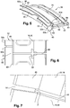
- the tongues 58 bear axially on this end portion (the support zone Z is visible to the Figures 6 and 7 ).
- the tongues 58 bear axially not on this end portion 32b but on the end portion 32a of the sector adjacent ring.
- the deflector 60 extends in the space E located between the hook 32 and the end 12 of the external platform 12a of the distributor and divides it into two parts respectively upstream and downstream. Its shape requires the leakage gases passing through the clearance J to flow downstream towards the labyrinth seal defined by the wipers 24. There is therefore less risk of leakage gas circulation at the level of hooks 32 of the ring sectors.
- the inter-sector clearances at the level of these hooks are also made watertight due to the circumferential offset between the hooks 32 and the deflectors 60. The invention thus makes it possible to effectively protect the casing 14 and to improve its service life and 'Also avoid leakage from the stream to the housing which improves the performance of the turbomachine.
Landscapes
- Engineering & Computer Science (AREA)
- Mechanical Engineering (AREA)
- General Engineering & Computer Science (AREA)
- Turbine Rotor Nozzle Sealing (AREA)
Abstract
Description
- La présente invention concerne un module de turbomachine, qui peut être une turbine ou faire partie d'une turbine par exemple.
- L'état de l'art comprend notamment les documents
FR-A1-3 914 350 WO-A1-2016/024060 . - Une turbine de turbomachine comprend un ou plusieurs étages comportant chacun un distributeur formé d'une rangée annulaire de pales fixes portées par un carter de la turbine, et une roue à aubes montée rotative en général en aval du distributeur. La roue est entourée par un anneau d'étanchéité qui est sectorisé et formé par des secteurs qui sont disposés circonférentiellement bout à bout et qui sont accrochés sur le carter de la turbine.
- Chaque secteur d'anneau comprend en général un corps à orientation circonférentielle qui porte un revêtement abradable fixé sur la surface interne du corps. Ce revêtement est par exemple du type en nid d'abeille et est destiné à s'user par frottement sur des léchettes externes des aubes de la roue, pour former un joint d'étanchéité à labyrinthe et minimiser les jeux radiaux entre la roue et les secteurs d'anneau.
- Chaque secteur d'anneau comprend à ses extrémités amont et aval des moyens d'accrochage sur le carter. Chaque secteur d'anneau peut comprendre à son extrémité amont un crochet circonférentiel qui définit une gorge annulaire dans laquelle est engagé, d'une part, un rail annulaire du carter, et d'autre part, un becquet d'accrochage aval du distributeur situé en amont. Le crochet de l'anneau a en section une forme générale en U ou en C et comprend deux parois circonférentielles coaxiales, respectivement interne et externe, reliées ensemble par une paroi médiane de fond. Le becquet d'accrochage aval du distributeur a une orientation circonférentielle et est maintenu serré radialement contre le rail de carter par l'intermédiaire du crochet circonférentiel amont de l'anneau, dont les parois circonférentielles s'étendent respectivement à l'intérieur du becquet du distributeur et à l'extérieur du rail de carter. Ceci permet de participer au maintien radial du distributeur vis-à-vis du carter.
- Il est connu d'utiliser un clinquant annulaire de protection du rail de carter, en particulier contre l'usure et les hautes températures. Ce clinquant peut être sectorisé et comprend alors une rangée annulaire de secteurs de clinquant disposés circonférentiellement bout à bout. Il a en section une forme générale en U ou en C et comprend deux parois circonférentielles coaxiales, respectivement interne et externe, reliées ensemble par une paroi médiane de fond.
- Les secteurs de clinquant sont en tôle et permettent d'éviter les contacts directs entre les crochets des secteurs d'anneau et le rail de carter, ce qui permet d'une part de protéger ce dernier contre l'usure par frottement et d'autre part de le protéger thermiquement de l'anneau qui peut être très chaud en fonctionnement du fait de sa proximité avec les gaz de combustion s'écoulant dans la veine de turbine.
- Du fait de la sectorisation de l'anneau, les bords longitudinaux des extrémités circonférentielles de deux secteurs adjacents de l'anneau sont en regard l'un de l'autre et sont séparés l'un de l'autre par un jeu circonférentiel à travers lequel des gaz chauds de la veine peuvent passer. Ces gaz chauds ont tendance à chauffer le carter, ce qui est néfaste pour plusieurs raisons. Une des raisons est qu'un chauffage du carter entraînerait une dilatation et une déformation de ce dernier qui risquerait d'altérer les jeux radiaux entre la roue mobile et l'anneau, et donc de diminuer les performances de la turbine. Par ailleurs, ces fuites de gaz ont un impact sur les performances de la turbomachine. Pour ces deux raisons, il est nécessaire d'étanchéifier au maximum les zones inter-secteurs. Une solution connue à ce problème consiste à intercaler des languettes d'étanchéité entre les secteurs d'anneau, qui sont logées dans des fentes des bords longitudinaux précités ses secteurs d'anneau.
- Cependant, du fait de la sectorisation du clinquant, les bords longitudinaux des extrémités circonférentielles de deux secteurs adjacents du clinquant sont en regard l'un de l'autre et sont séparés l'un de l'autre par un jeu circonférentiel. Dans la technique actuelle, les jeux circonférentiels entre les secteurs de clinquant peuvent être décalés circonférentiellement par rapport aux jeux circonférentiels entre les secteurs d'anneau, et en particulier par rapport aux jeux circonférentiels entre les crochets des secteurs d'anneau au niveau desquels il n'est pas possible de monter des languettes du type précité pour des raisons d'encombrement notamment. Des gaz chauds peuvent ainsi passer à travers les jeux circonférentiels entre les crochets des secteurs d'anneau et impacter les secteurs de clinquant, ce qui va réchauffer par conduction le rail de carter, et risque donc de réduire sa durée de vie.
- Le document
WO-A1-2016/024060 propose de décaler circonférentiellement chaque clinquant par rapport au crochet associé de façon à mieux protéger le rail de carter car les gaz qui seraient susceptibles de passer entre les bords des extrémités circonférentielles des secteurs d'anneau sont bloqués par les secteurs de clinquant (du fait de leur décalage circonférentiel vis-à-vis des secteurs d'anneau) et ne parviennent pas jusqu'au rail de carter. Cependant, cette solution ne permet pas de protéger le carter des fuites inter-secteurs qui ont lieu au niveau des parois médianes de fond des crochets de l'anneau. - Le document
FR-A1-3 914 350 - Par ailleurs, les gaz de la veine qui sont susceptibles de chauffer et détériorer le carter s'échappent de la veine en passant à travers un jeu axial entre la périphérie externe de la roue et la périphérie externe du distributeur situé en amont de la roue. Ces gaz traversent ce jeu en passant radialement de l'intérieur vers l'extérieur et pénètrent dans un espace annulaire délimité, à l'amont, par le becquet d'accrochage aval du distributeur, et à l'aval, par une léchette d'étanchéité amont de la roue. Cet espace annulaire est donc le lieu de circulation de gaz de fuite, qui est susceptible de passer à travers les jeux inter-secteurs et d'atteindre le carter.
- La présente invention a notamment pour but d'apporter une solution simple, efficace et économique à ce besoin en améliorant notamment la protection thermique du rail de carter dans le cas précité.
- La présente invention propose ainsi un module d'étanchéité de turbomachine, en particulier d'aéronef, ce module d'étanchéité s'étendant autour d'un axe et comprenant un distributeur fixé à un carter et comportant au moins une pale reliée à une plateforme externe, la plateforme externe comportant un becquet de fixation au carter, le module de turbine comportant en outre une roue à aubes montée rotative à l'intérieur du carter et entourée par un anneau d'étanchéité accroché à ce carter, cet anneau étant sectorisé et comportant une rangée annulaire de secteurs d'anneau disposés de façon à ce que des bords d'extrémité circonférentielle de deux secteurs adjacents soient en regard l'un de l'autre, chaque secteur d'anneau comportant un corps portant un revêtement abradable configuré pour coopérer avec au moins une léchette portée par la roue et un crochet qui s'étend circonférentiellement en étant situé en amont dudit revêtement abradable et qui est configuré pour coopérer avec un rail d'accrochage du carter, ce crochet ayant en section une forme générale en C dont l'ouverture est orientée axialement vers l'amont et destinée à recevoir ledit rail. L'invention se caractérise en ce que chaque secteur d'anneau comporte en outre un déflecteur qui est disposé en amont dudit revêtement et qui s'étend radialement vers l'intérieur et vers l'amont par rapport à l'axe de façon à ce que son extrémité radialement interne s'étende autour d'une extrémité aval de la plateforme externe du distributeur. L'invention se caractérise également en ce que chaque crochet a une étendue circonférentielle identique à celle dudit déflecteur, et les extrémités circonférentielles dudit crochet sont décalées en direction circonférentielle des extrémités circonférentielles dudit déflecteur.
- Le déflecteur est ainsi destiné à être situé dans l'espace annulaire précité, entre la périphérie externe de la roue et celle du distributeur situé en amont, et permet de limiter les circulations de gaz dans cet espace. Il permet en particulier de limiter la circulation des gaz de fuite au niveau du crochet amont de chaque secteur d'anneau et donc de réduire le risque de passage de ces gaz dans les jeux inter-secteurs au niveau de leurs crochets. Le carter est ainsi mieux protéger et a une durée de vie optimisée.
- Par ailleurs, le décalage des extrémités est avantageux car les gaz qui sont susceptibles de passer radialement de l'intérieur vers l'extérieur à travers les jeux circonférentiels entre les extrémités circonférentielles des déflecteurs, sont bloqués par les crochets qui s'étendent en regard de ces jeux, et les gaz qui sont susceptibles de passer radialement de l'intérieur vers l'extérieur à travers les jeux circonférentiels entre les extrémités circonférentielles des crochets, sont bloqués par les secteurs de déflecteur qui s'étendent en regard de ces jeux,
- Le module selon l'invention peut comprendre une ou plusieurs des caractéristiques suivantes, prises isolément ou en combinaison les unes avec les autres :
- ledit déflecteur comprend un secteur de tôle annulaire intercalé axialement entre le crochet, d'une part, et le revêtement et/ou corps, d'autre part,
- le secteur de tôle a en section une forme générale en V dont une portion radialement externe s'étend radialement, et dont une portion radialement interne est tronconique et s'étend, d'amont en aval, radialement vers l'intérieur,
- le crochet comprend une paroi médiane de fond qui relie deux parois circonférentielles respectivement radialement interne et externe, la portion radialement externe du secteur de tôle étant intercalée axialement entre la paroi de fond du crochet, et le revêtement et/ou le corps,
- chaque déflecteur a une étendue circonférentielle identique à celle dudit corps et dudit revêtement, et les extrémités circonférentielles dudit déflecteur sont sensiblement alignées axialement avec celles dudit corps et dudit revêtement,
- ledit corps comprend à ses extrémités circonférentielles des fentes de logement de languettes d'étanchéité inter-secteurs, et ledit déflecteur comprend à ses extrémités circonférentielles des encoches alignées axialement avec ces fentes de façon à ce que des extrémités axiales amont d'au moins certaines desdites languettes d'étanchéité pénètrent dans ces encoches ; les languettes s'étendent ainsi au plus près du crochet, ce qui optimise l'étanchéité inter-secteurs,
- chaque secteur d'anneau comprend à une de ses extrémités circonférentielles au moins une languette d'étanchéité dont l'extrémité axiale amont traverse une encoche du déflecteur et est en appui axial sur un crochet de ce secteur d'anneau, et à l'autre de ses extrémités circonférentielles au moins une languette d'étanchéité dont l'extrémité axiales amont traverse une encoche du déflecteur et est en appui axial sur un crochet d'un secteur d'anneau adjacent.
- La présente invention concerne encore une turbomachine, comportant au moins un module d'étanchéité tel que décrit ci-dessus.
- L'invention sera mieux comprise et d'autres détails, caractéristiques et avantages de l'invention apparaîtront à la lecture de la description suivante faite à titre d'exemple non limitatif et en référence aux dessins annexés, dans lesquels :
- la
figure 1 est une demi-vue schématique partielle en coupe axiale d'une turbine de turbomachine ; - la
figure 2 est une demi-vue schématique partielle en coupe axiale d'une autre turbine de turbomachine ; - la
figure 3 est une vue schématique partielle en perspective et à plus grande échelle d'un anneau d'étanchéité de la turbine de lafigure 2 ; - la
figure 4 est une demi-vue schématique partielle en coupe axiale d'un module de turbomachine selon l'invention ; - la
figure 5 est une vue schématique en perspective d'un secteur d'anneau d'étanchéité du module de lafigure 4 ; et - les
figures 6 et 7 sont des vues schématiques en perspective et à plus grande échelle des jeux inter-secteurs de l'anneau d'étanchéité du module de lafigure 4 . - On se réfère d'abord à la
figure 1 qui représente une turbine 10, ici basse-pression, d'une turbomachine telle qu'un turboréacteur ou un turbopropulseur d'avion, cette turbine comportant plusieurs étages (dont un seul est ici représenté) comportant chacun un distributeur 12 formé d'une rangée annulaire de pales fixes portées par un carter 14 de la turbine, et une roue à aubes 16 montée en aval du distributeur 12 et tournant autour d'un axe (non visible) dans un anneau 18 accroché au carter 14. - L'anneau 18 est sectorisé et formé de plusieurs secteurs qui sont portés circonférentiellement bout à bout par le carter 14 de la turbine.
- Chaque secteur d'anneau 18 comprend un corps 20 qui s'étend circonférentiellement et un revêtement 22 de matière abradable fixé par brasage et/ou soudage sur la surface radialement interne du corps 20, ce revêtement 22 étant du type en nid d'abeille et étant destiné à s'user par frottement sur des léchettes externes 24 des aubes de la roue 16 pour minimiser les jeux radiaux entre la roue et les secteurs d'anneau 18. Les léchettes 24 sont formées en saillie sur une plateforme externe 16a de la roue 16, la plateforme externe 16a étant reliée à une pale de la roue à aubes.
- Chaque secteur d'anneau 18 comprend à son extrémité amont un crochet 32 à section en C ou U qui s'étend circonférentiellement et dont l'ouverture débouche vers l'amont, ce crochet 32 étant engagé axialement depuis l'aval sur un becquet d'accrochage 34 orienté vers l'aval du distributeur 12 qui s'étend circonférentiellement en amont des secteurs d'anneau 18, d'une part, et sur un rail cylindrique 36 du carter 14 sur lequel est accroché ce distributeur, d'autre part. Le becquet 34 a une forme générale en L et est en saillie d'une plateforme 12a du distributeur 12, à laquelle sont reliées au moins une pale du distributeur.
- Le crochet 32 de chaque secteur d'anneau 18 comprend deux parois 38 et 40 s'étendant circonférentiellement et vers l'amont, chaque paroi, respectivement radialement externe et radialement interne sont reliées entre elles à leurs extrémités aval par une paroi médiane de fond 42 sensiblement radiale, et qui s'étendent respectivement radialement à l'extérieur et à l'intérieur du rail 36, la paroi interne 40 maintenant radialement le becquet 34 du distributeur contre le rail 36.
- Tel qu'illustré en
figure 1 , le maintien circonférentiel du distributeur 12 est assuré par l'intermédiaire d'un pion anti-rotation 44 qui est porté par le carter 14 et est engagé dans une encoche du distributeur 12. Son maintien axial vers l'aval est assuré par un jonc annulaire 46 fendu qui est monté dans une gorge annulaire 48 du rail 36, qui débouche radialement vers l'intérieur. Dans ce cas, le becquet 34 du distributeur 12 est en appui axial vers l'aval sur le jonc 46 qui est maintenu radialement dans la gorge du rail de carter par la paroi interne 40, qui s'étend radialement à l'intérieur du jonc 46. En variante, la fonction d'arrêt axial du jonc 46 peut être assurée directement par le rail de carter 36. - Les extrémités aval des secteurs d'anneau 18 sont serrées radialement sur un rail cylindrique 30 du carter par le distributeur situé en aval des secteurs d'anneau. Les secteurs d'anneau 18 sont en appui radial vers l'extérieur sur une face cylindrique radialement interne du rail 30 du carter, et vers l'intérieur sur une face cylindrique radialement externe d'un rebord cylindrique 28 du distributeur aval. Les extrémités aval des secteurs d'anneau 18 sont en outre serrées axialement via des ergots sur le rail cylindrique 30.
- Pour protéger thermiquement et contre l'usure le rail 36, il est également connu d'utiliser un clinquant annulaire 50 qui est sectorisé et comprend une rangée annulaire de secteurs de clinquant disposés circonférentiellement bout à bout. Il a en section une forme générale en C ou U et comprend deux parois annulaires coaxiales, respectivement interne 52 et externe 54, reliées ensemble par une paroi médiane de fond 56.
- Le clinquant 50 est monté sur le rail de carter 36 et sur le becquet 34 du distributeur 12 de sorte que les parois internes 52 des secteurs de clinquant 50 soient intercalées entre les parois internes 40 des crochets 32 des secteurs d'anneau 18, d'une part, et le becquet 34 du distributeur 12 et le jonc annulaire 46, d'autre part, que les parois externes 54 des secteurs de clinquant soient intercalées entre les parois externes 38 des crochets 32 des secteurs d'anneau et le rail de carter 36, et que les parois de fond 56 des secteurs de clinquant soient intercalées entre les parois de fond 42 des crochets des secteurs d'anneau et le rail de carter 36.
- Les secteurs de clinquant 50 sont en tôle et permettent d'éviter les contacts directs entre les crochets 32 des secteurs d'anneau 18 et le rail de carter 36, ce qui permet d'une part de protéger ce dernier contre l'usure par frottement et d'autre part de le protéger thermiquement de l'anneau qui peut être très chaud en fonctionnement du fait de sa proximité avec les gaz de combustion s'écoulant dans la veine de turbine.
- Pour éviter des fuites de gaz vers le carter 14, il est également connu de monter des languettes d'étanchéité 58 au niveau des jeux circonférentiels inter-secteurs. Les bords longitudinaux des extrémités circonférentielles des secteurs d'anneau comprennent des fentes de montage des languettes 58. Les languettes 58 ont chacune une forme générale allongée et plane et comprennent chacune un bord longitudinal engagé dans une fente du bord d'un secteur d'anneau et un bord longitudinal opposé engagé dans une fente du bord en regard d'un secteur d'anneau adjacent.
- La
figure 1 représente une première technologie d'anneau d'étanchéité 18 dans lequel le corps 20 et le crochet 32 sont formés d'une seule pièce. - La
figure 2 représente une seconde technologie d'anneau d'étanchéité 18 dans lequel le corps 20 et le crochet 32 sont formés de pièces assemblées. Les références utilisées dans lafigure 2 sont les mêmes que celles de lafigure 1 dans la mesure où elles désignent les mêmes éléments. - La seconde technologie couvre le cas où le crochet 32 est fixé sous le corps, juste en amont du revêtement 22 (comme c'est le cas dans la demande
FR-A1-3 914 350 - En fonctionnement, les gaz de combustion s'écoulent d'amont en aval dans la veine de turbine, à travers les pales des distributeurs 12 et les aubes mobiles des roues 16. La périphérie externe de chaque distributeur 12 est séparée par un jeu axial J de la périphérie externe de la roue 16 adjacente, qui peut être traversé par des gaz de fuite. La coopération des léchettes 24 avec le revêtement abradable 22 limite le passage de ces gaz de fuite d'amont en aval entre la roue 16 et l'anneau 18. Les gaz de fuite circulent alors dans l'espace annulaire E s'étendant radialement entre les plateformes externes 12a, 16a du distributeur 12 et de la roue 16, et axialement entre le becquet aval 34 du distributeur 12 et la léchette amont 24a de la roue 16.
- Les languettes 58 limitent le passage des gaz depuis l'espace E radialement vers l'extérieur, au niveau des jeux circonférentiels entre les corps 20 des secteurs d'anneau. Cependant, comme cela est mieux visible à la
figure 3 , des jeux circonférentiels sont toujours présents entre les crochets 32 et des gaz peuvent passer depuis l'espace E radialement vers l'extérieur, en particulier entre les parois médiane de fond 42 des crochets 32 (flèche F). - Les
figures 4 et suivantes représentent un mode de réalisation de l'invention qui permet de résoudre au moins une partie de ces problèmes. Les références utilisées dans lafigure 3 sont les mêmes que celles des précédentes figures dans la mesure où elles désignent les mêmes éléments. - L'anneau 18 diffère de celui décrit dans ce qui précède notamment en ce que chaque secteur d'anneau comporte en outre un déflecteur 60 qui est disposé en amont du revêtement 22 et qui s'étend radialement vers l'intérieur par rapport à l'axe précité de façon à ce que son extrémité radialement interne s'étende autour de l'extrémité aval de la plateforme externe 12a du distributeur 12. Dans l'exemple représenté, le déflecteur 60 est formé par une pièce indépendante du crochet 32 et du corps 20, et qui est intercalée axialement entre le crochet 32 situé à l'amont, et le corps 20 et le revêtement 22 situés à l'aval. Le déflecteur 60 peut être formé par un secteur de tôle annulaire.
- Le déflecteur 60 a ici une orientation générale incurvée et une forme générale en V. Il comporte ainsi une portion radialement externe 60a s'étendant dans un plan sensiblement perpendiculaire à l'axe précité, et une portion radialement interne 60b qui est tronconique.
- La portion 60a est intercalée entre la paroi médiane de fond 42 du crochet 32 et les extrémités amont du corps 20 et du revêtement 22.
- La portion 60b s'étend d'aval en amont, radialement vers l'intérieur. Sa périphérie interne définit un diamètre D qui est inférieur aux plus petits diamètres internes D1, D2 du crochet 32 et du revêtement 22. Cette périphérie interne entoure avec ici un faible jeu radial l'extrémité de la plateforme externe 12a du distributeur 12 (
figure 4 ). - Le déflecteur 60 a une étendue circonférentielle autour de l'axe qui est identique à celle du corps 20 et du revêtement 22. Les extrémités circonférentielles du déflecteur 60 sont sensiblement alignées axialement avec celles du corps 20 et du revêtement 22, comme cela est visible à la
figure 5 . - La
figure 5 permet de voir également que le déflecteur 60 comprend à ses extrémités circonférentielles des encoches 62 alignées axialement avec les fentes 64 de logement des languettes 58 d'étanchéité inter-secteurs. Ces encoches 62 sont conçues pour pouvoir être traversées par les languettes 58. Chaque encoche 62 a une hauteur (ou dimension radiale) au moins égale à la hauteur (ou dimension radiale des fentes 64 de logement des languettes), et une largeur (ou dimension circonférentielle) au moins égale à la dimension circonférentielle entre les fonds des deux fentes 64 en regard de logement des languettes. - On notera dans les dessins que le bord longitudinal de chaque extrémité circonférentielle d'un secteur d'anneau peut comprendre deux fentes 64 de logement de deux languettes 58, qui ont des longueurs différentes et s'étendent l'une au-dessus de l'autre en direction radiale. Les extrémités amont des fentes 64 se rejoignent à l'extrémité amont de chaque bord et communiquent toutes les deux avec l'encoche 62, si bien que les deux languettes 58 de chaque bord sont susceptibles de traverser l'encoche 62 (
figures 4 et5 ). En variante, le bord de chaque extrémité circonférentielle d'un secteur d'anneau pourrait porter qu'une seule languette 58. - Chaque crochet 32 a une étendue circonférentielle identique à celle du déflecteur 60, et les extrémités circonférentielles du crochet 32 sont décalées en direction circonférentielle des extrémités circonférentielles du déflecteur (
figure 5 ). Chaque crochet 32 comprend ainsi une partie d'extrémité circonférentielle 32a qui fait saillie par rapport aux extrémités circonférentielles des autres pièces du secteur d'anneau, et une autre partie d'extrémité circonférentielle 32b qui est en retrait par rapport aux extrémités circonférentielles des autres pièces du secteur d'anneau (figure 5 ). - Lors du montage de l'anneau 18 sur le carter, on comprend donc que les secteurs d'anneau s'emboiteront circonférentiellement les uns dans les autres (
figure 6 ). - Au niveau de l'extrémité circonférentielle de chaque secteur d'anneau comportant la portion d'extrémité 32a en saillie, les languettes 58 prennent appui axialement sur cette portion d'extrémité (la zone d'appui Z est visible aux
figures 6 et 7 ). Au niveau de l'extrémité circonférentielle de chaque secteur d'anneau comportant la portion d'extrémité 32b en retrait, les languettes 58 prennent appui axialement non pas sur cette portion d'extrémité 32b mais sur la portion d'extrémité 32a du secteur d'anneau adjacent. - Comme on le voit à la
figure 4 , le déflecteur 60 s'étend dans l'espace E situé entre le crochet 32 et l'extrémité 12 de la plateforme externe 12a du distributeur et le divise en deux parties respectivement amont et aval. Sa forme impose aux gaz de fuite passant à travers le jeu J de s'écouler vers l'aval en direction du joint d'étanchéité à labyrinthe défini par les léchettes 24. Il y a donc moins de risque de circulation de gaz de fuite au niveau des crochets 32 des secteurs d'anneau. Les jeux inter-secteurs au niveau de ces crochets sont par ailleurs rendus étanches du fait du décalage circonférentiel entre les crochets 32 et les déflecteurs 60. L'invention permet ainsi de protéger efficacement le carter 14 et d'améliorer sa durée de vie et d'éviter également des fuites de la veine vers le carter ce qui améliore le rendement de la turbomachine.
Claims (8)
- Module d'étanchéité de turbine de turbomachine, en particulier d'aéronef, ce module d'étanchéité s'étendant autour d'un axe et comprenant un distributeur (12) fixé à un carter (14), le distributeur (12) ayant au moins une pale reliée à une plateforme externe (12a), la plateforme externe (12a) comportant un becquet (34) de fixation au carter (14), le module d'étanchéité comportant en outre une roue (16) à aubes montée rotative à l'intérieur du carter (14) et entourée par un anneau d'étanchéité (18) accroché à ce carter (14), cet anneau d'étanchéité (18) étant sectorisé et comportant une rangée annulaire de secteurs d'anneau disposés de façon à ce que des bords d'extrémité circonférentielle de deux secteurs adjacents soient en regard l'un de l'autre, chaque secteur d'anneau comportant un corps (20) portant un revêtement abradable (22) configuré pour coopérer avec au moins une léchette (24) portée par la roue (16) et un crochet (32) qui s'étend circonférentiellement en étant situé en amont dudit revêtement abradable (22) et qui est configuré pour coopérer avec un rail (36) d'accrochage du carter (14), ce crochet (32) ayant en section une forme générale en C dont l'ouverture est orientée axialement vers l'amont et destinée à recevoir ledit rail (36), caractérisé en ce que chaque secteur d'anneau comporte en outre un déflecteur (60) qui est disposé en amont dudit revêtement et qui s'étend radialement vers l'intérieur et vers l'amont par rapport à l'axe de façon à ce que son extrémité radialement interne s'étende autour d'une extrémité aval de la plateforme externe (12a) du distributeur (12), et en ce que chaque crochet (32) a une étendue circonférentielle identique à celle dudit déflecteur (60), et les extrémités circonférentielles dudit crochet (32) sont décalées en direction circonférentielle des extrémités circonférentielles dudit déflecteur (60).
- Module d'étanchéité selon la revendication précédente, dans lequel ledit déflecteur (60) comprend un secteur de tôle annulaire intercalé axialement entre le crochet (32), d'une part, et le revêtement (22) et/ou corps (20), d'autre part.
- Module d'étanchéité selon la revendication précédente, dans lequel le secteur de tôle a en section une forme générale en V dont une portion radialement externe (62a) s'étend radialement, et dont une portion radialement interne (62b) est tronconique et s'étend, d'aval en amont, radialement vers l'intérieur.
- Module d'étanchéité selon la revendication précédente, dans lequel le crochet (32) comprend une paroi médiane (42) de fond qui relie deux parois respectivement radialement interne (40) et externe (38) qui s'étendent circonférentiellement, la portion radialement externe du secteur de tôle étant intercalée axialement entre la paroi de fond du crochet (32), et le revêtement (22) et/ou le corps (20).
- Module d'étanchéité selon l'une des revendications précédentes, dans lequel chaque déflecteur (60) a une étendue circonférentielle identique à celle dudit corps (20) et dudit revêtement (22), et les extrémités circonférentielles dudit déflecteur (60) sont sensiblement alignées axialement avec celles dudit corps (20) et dudit revêtement (22).
- Module d'étanchéité selon la revendication précédente, dans lequel ledit corps (20) comprend à ses extrémités circonférentielles des fentes de logement de languettes (58) d'étanchéité inter-secteurs, et ledit déflecteur (60) comprend à ses extrémités circonférentielles des encoches (62) alignées axialement avec ces fentes de façon à ce que des extrémités axiales amont d'au moins certaines desdites languettes d'étanchéité pénètrent dans ces encoches (62).
- Module d'étanchéité selon l'une des revendications précédentes, dans lequel chaque secteur d'anneau comprend à une de ses extrémités circonférentielles au moins une languette d'étanchéité (58) dont l'extrémité axiale amont traverse une encoche (62) du déflecteur (60) et est en appui axial sur un crochet (32) de ce secteur d'anneau, et à l'autre de ses extrémités circonférentielles au moins une languette d'étanchéité dont l'extrémité axiale amont traverse une encoche (62) du déflecteur et est en appui axial sur un crochet d'un secteur d'anneau adjacent.
- Turbomachine, comportant au moins un module d'étanchéité selon l'une des revendications précédentes.
Applications Claiming Priority (1)
| Application Number | Priority Date | Filing Date | Title |
|---|---|---|---|
| FR1856139A FR3083563B1 (fr) | 2018-07-03 | 2018-07-03 | Module d'etancheite de turbomachine d'aeronef |
Publications (2)
| Publication Number | Publication Date |
|---|---|
| EP3591178A1 true EP3591178A1 (fr) | 2020-01-08 |
| EP3591178B1 EP3591178B1 (fr) | 2022-08-10 |
Family
ID=63896322
Family Applications (1)
| Application Number | Title | Priority Date | Filing Date |
|---|---|---|---|
| EP19183350.8A Active EP3591178B1 (fr) | 2018-07-03 | 2019-06-28 | Module d'étanchéité de turbomachine |
Country Status (4)
| Country | Link |
|---|---|
| US (1) | US11035244B2 (fr) |
| EP (1) | EP3591178B1 (fr) |
| CN (1) | CN110685753B (fr) |
| FR (1) | FR3083563B1 (fr) |
Cited By (4)
| Publication number | Priority date | Publication date | Assignee | Title |
|---|---|---|---|---|
| FR3114840A1 (fr) * | 2020-10-05 | 2022-04-08 | Safran Aircraft Engines | Ensemble annulaire pour turbine de turbomachine |
| FR3114841A1 (fr) * | 2020-10-05 | 2022-04-08 | Safran Aircraft Engines | Ensemble annulaire pour turbine de turbomachine |
| FR3122692A1 (fr) * | 2021-05-07 | 2022-11-11 | Safran Aircraft Engines | Pièce annulaire d’étanchéité pour aubes mobiles de turbine de turbomachine |
| FR3149037A1 (fr) * | 2023-05-26 | 2024-11-29 | Safran Aircraft Engines | Ensemble pour turbomachine comprenant un élément d’étanchéité et élément d’étanchéité pour un tel ensemble pour turbomachine |
Families Citing this family (6)
| Publication number | Priority date | Publication date | Assignee | Title |
|---|---|---|---|---|
| FR3100838B1 (fr) * | 2019-09-13 | 2021-10-01 | Safran Aircraft Engines | Anneau d’etancheite de turbomachine |
| FR3107079B1 (fr) * | 2020-02-07 | 2022-01-21 | Safran Aircraft Engines | Aube de turbomachine d’aeronef |
| FR3108935B1 (fr) * | 2020-04-02 | 2022-03-04 | Safran Aircraft Engines | Dispositif de distribution d’huile d’un palier a roulement de turbomachine d’aeronef |
| FR3111382B1 (fr) | 2020-06-11 | 2022-12-23 | Safran Aircraft Engines | Ensemble annulaire pour turbine de turbomachine |
| FR3140112A1 (fr) * | 2022-09-22 | 2024-03-29 | Safran Aircraft Engines | Amélioration de l’étanchéité dans une turbine de turbomachine |
| FR3146709B1 (fr) * | 2023-03-16 | 2025-06-27 | Safran Aircraft Engines | Ensemble d’étanchéité avec tôle thermique pour turbine à gaz |
Citations (6)
| Publication number | Priority date | Publication date | Assignee | Title |
|---|---|---|---|---|
| EP1840339A1 (fr) * | 2006-03-30 | 2007-10-03 | Snecma | Dispositif de fixation de secteurs d'anneau autour d'une roue de turbine d'une turbomachine |
| FR2914350A1 (fr) | 2007-03-30 | 2008-10-03 | Snecma Sa | Enveloppe externe etanche pour une roue de turbine de turbomachine |
| WO2013156734A1 (fr) * | 2012-04-20 | 2013-10-24 | Snecma | Etage de turbine pour une turbomachine |
| US20140186163A1 (en) * | 2012-12-31 | 2014-07-03 | United Technologies Corporation | Blade outer air seal having shiplap structure |
| WO2016024060A1 (fr) | 2014-08-14 | 2016-02-18 | Snecma | Module de turbomachine |
| FR3058756A1 (fr) * | 2016-11-15 | 2018-05-18 | Safran Aircraft Engines | Turbine pour turbomachine |
Family Cites Families (10)
| Publication number | Priority date | Publication date | Assignee | Title |
|---|---|---|---|---|
| GB2249356B (en) * | 1990-11-01 | 1995-01-18 | Rolls Royce Plc | Shroud liners |
| US5971703A (en) * | 1997-12-05 | 1999-10-26 | Pratt & Whitney Canada Inc. | Seal assembly for a gas turbine engine |
| DE10122464C1 (de) * | 2001-05-09 | 2002-03-07 | Mtu Aero Engines Gmbh | Mantelring |
| US8206092B2 (en) * | 2007-12-05 | 2012-06-26 | United Technologies Corp. | Gas turbine engines and related systems involving blade outer air seals |
| US8240985B2 (en) * | 2008-04-29 | 2012-08-14 | Pratt & Whitney Canada Corp. | Shroud segment arrangement for gas turbine engines |
| US9506367B2 (en) * | 2012-07-20 | 2016-11-29 | United Technologies Corporation | Blade outer air seal having inward pointing extension |
| US9115596B2 (en) * | 2012-08-07 | 2015-08-25 | United Technologies Corporation | Blade outer air seal having anti-rotation feature |
| ES2620482T3 (es) * | 2012-08-09 | 2017-06-28 | MTU Aero Engines AG | Impermeabilización del canal de flujo de una turbomáquina |
| EP2846001B1 (fr) * | 2013-09-06 | 2023-01-11 | MTU Aero Engines AG | Procédés de montage et de démontage d'un rotor d'une turbine à gaz, et outil associé |
| US10662794B2 (en) * | 2017-10-19 | 2020-05-26 | Rolls-Royce Corporation | Strip seal axial assembly groove |
-
2018
- 2018-07-03 FR FR1856139A patent/FR3083563B1/fr active Active
-
2019
- 2019-06-28 EP EP19183350.8A patent/EP3591178B1/fr active Active
- 2019-07-01 US US16/459,406 patent/US11035244B2/en active Active
- 2019-07-03 CN CN201910593253.7A patent/CN110685753B/zh active Active
Patent Citations (6)
| Publication number | Priority date | Publication date | Assignee | Title |
|---|---|---|---|---|
| EP1840339A1 (fr) * | 2006-03-30 | 2007-10-03 | Snecma | Dispositif de fixation de secteurs d'anneau autour d'une roue de turbine d'une turbomachine |
| FR2914350A1 (fr) | 2007-03-30 | 2008-10-03 | Snecma Sa | Enveloppe externe etanche pour une roue de turbine de turbomachine |
| WO2013156734A1 (fr) * | 2012-04-20 | 2013-10-24 | Snecma | Etage de turbine pour une turbomachine |
| US20140186163A1 (en) * | 2012-12-31 | 2014-07-03 | United Technologies Corporation | Blade outer air seal having shiplap structure |
| WO2016024060A1 (fr) | 2014-08-14 | 2016-02-18 | Snecma | Module de turbomachine |
| FR3058756A1 (fr) * | 2016-11-15 | 2018-05-18 | Safran Aircraft Engines | Turbine pour turbomachine |
Cited By (5)
| Publication number | Priority date | Publication date | Assignee | Title |
|---|---|---|---|---|
| FR3114840A1 (fr) * | 2020-10-05 | 2022-04-08 | Safran Aircraft Engines | Ensemble annulaire pour turbine de turbomachine |
| FR3114841A1 (fr) * | 2020-10-05 | 2022-04-08 | Safran Aircraft Engines | Ensemble annulaire pour turbine de turbomachine |
| FR3122692A1 (fr) * | 2021-05-07 | 2022-11-11 | Safran Aircraft Engines | Pièce annulaire d’étanchéité pour aubes mobiles de turbine de turbomachine |
| FR3149037A1 (fr) * | 2023-05-26 | 2024-11-29 | Safran Aircraft Engines | Ensemble pour turbomachine comprenant un élément d’étanchéité et élément d’étanchéité pour un tel ensemble pour turbomachine |
| WO2024246455A1 (fr) * | 2023-05-26 | 2024-12-05 | Safran Aircraft Engines | Ensemble pour turbomachine comprenant un élément d'étanchéité et élément d'étanchéité pour un tel ensemble pour turbomachine |
Also Published As
| Publication number | Publication date |
|---|---|
| FR3083563A1 (fr) | 2020-01-10 |
| US11035244B2 (en) | 2021-06-15 |
| CN110685753A (zh) | 2020-01-14 |
| US20200011194A1 (en) | 2020-01-09 |
| FR3083563B1 (fr) | 2020-07-24 |
| CN110685753B (zh) | 2023-04-28 |
| EP3591178B1 (fr) | 2022-08-10 |
Similar Documents
| Publication | Publication Date | Title |
|---|---|---|
| EP3591178B1 (fr) | Module d'étanchéité de turbomachine | |
| CA2956882C (fr) | Module de turbomachine | |
| EP2334909B1 (fr) | Etanchéité entre une chambre de combustion et un distributeur de turbine dans une turbomachine | |
| EP1847686B1 (fr) | Dispositif de fixation de secteurs d'anneau sur un carter de turbine d'une turbomachine | |
| EP2839117B1 (fr) | Étage de turbine pour une turbomachine | |
| CA2781936C (fr) | Isolation d'un rebord circonferentiel d'un carter externe de turbomachine vis-a-vis d'un secteur d'anneau correspondant | |
| FR2928963A1 (fr) | Distributeur de turbine pour une turbomachine. | |
| EP2060751B1 (fr) | Etage de turbine ou de compresseur d'un turboréacteur | |
| CA2891076A1 (fr) | Support de tube d'evacuation d'air dans une turbomachine | |
| FR2919345A1 (fr) | Anneau pour une roue de turbine de turbomachine. | |
| FR2961848A1 (fr) | Etage de turbine | |
| EP4028644B1 (fr) | Anneau d'étanchéité de turbomachine | |
| FR2999641A1 (fr) | Etage de turbomachine | |
| FR2899273A1 (fr) | Dispositif de fixation de secteurs d'anneau sur un carter de turbine d'une turbomachine | |
| FR2960590A1 (fr) | Distributeur de turbine pour une turbomachine | |
| EP3853445B1 (fr) | Etancheite d'une turbine | |
| FR2944554A1 (fr) | Turbine haute-pression de turbomachine |
Legal Events
| Date | Code | Title | Description |
|---|---|---|---|
| PUAI | Public reference made under article 153(3) epc to a published international application that has entered the european phase |
Free format text: ORIGINAL CODE: 0009012 |
|
| STAA | Information on the status of an ep patent application or granted ep patent |
Free format text: STATUS: REQUEST FOR EXAMINATION WAS MADE |
|
| 17P | Request for examination filed |
Effective date: 20190628 |
|
| AK | Designated contracting states |
Kind code of ref document: A1 Designated state(s): AL AT BE BG CH CY CZ DE DK EE ES FI FR GB GR HR HU IE IS IT LI LT LU LV MC MK MT NL NO PL PT RO RS SE SI SK SM TR |
|
| AX | Request for extension of the european patent |
Extension state: BA ME |
|
| STAA | Information on the status of an ep patent application or granted ep patent |
Free format text: STATUS: EXAMINATION IS IN PROGRESS |
|
| 17Q | First examination report despatched |
Effective date: 20201112 |
|
| GRAP | Despatch of communication of intention to grant a patent |
Free format text: ORIGINAL CODE: EPIDOSNIGR1 |
|
| STAA | Information on the status of an ep patent application or granted ep patent |
Free format text: STATUS: GRANT OF PATENT IS INTENDED |
|
| GRAJ | Information related to disapproval of communication of intention to grant by the applicant or resumption of examination proceedings by the epo deleted |
Free format text: ORIGINAL CODE: EPIDOSDIGR1 |
|
| STAA | Information on the status of an ep patent application or granted ep patent |
Free format text: STATUS: EXAMINATION IS IN PROGRESS |
|
| INTG | Intention to grant announced |
Effective date: 20220124 |
|
| INTC | Intention to grant announced (deleted) | ||
| GRAP | Despatch of communication of intention to grant a patent |
Free format text: ORIGINAL CODE: EPIDOSNIGR1 |
|
| STAA | Information on the status of an ep patent application or granted ep patent |
Free format text: STATUS: GRANT OF PATENT IS INTENDED |
|
| INTG | Intention to grant announced |
Effective date: 20220404 |
|
| GRAS | Grant fee paid |
Free format text: ORIGINAL CODE: EPIDOSNIGR3 |
|
| GRAA | (expected) grant |
Free format text: ORIGINAL CODE: 0009210 |
|
| STAA | Information on the status of an ep patent application or granted ep patent |
Free format text: STATUS: THE PATENT HAS BEEN GRANTED |
|
| AK | Designated contracting states |
Kind code of ref document: B1 Designated state(s): AL AT BE BG CH CY CZ DE DK EE ES FI FR GB GR HR HU IE IS IT LI LT LU LV MC MK MT NL NO PL PT RO RS SE SI SK SM TR |
|
| REG | Reference to a national code |
Ref country code: AT Ref legal event code: REF Ref document number: 1510696 Country of ref document: AT Kind code of ref document: T Effective date: 20220815 Ref country code: CH Ref legal event code: EP |
|
| REG | Reference to a national code |
Ref country code: DE Ref legal event code: R096 Ref document number: 602019018003 Country of ref document: DE |
|
| REG | Reference to a national code |
Ref country code: IE Ref legal event code: FG4D Free format text: LANGUAGE OF EP DOCUMENT: FRENCH |
|
| REG | Reference to a national code |
Ref country code: NL Ref legal event code: MP Effective date: 20220810 |
|
| REG | Reference to a national code |
Ref country code: LT Ref legal event code: MG9D |
|
| PG25 | Lapsed in a contracting state [announced via postgrant information from national office to epo] |
Ref country code: SE Free format text: LAPSE BECAUSE OF FAILURE TO SUBMIT A TRANSLATION OF THE DESCRIPTION OR TO PAY THE FEE WITHIN THE PRESCRIBED TIME-LIMIT Effective date: 20220810 Ref country code: RS Free format text: LAPSE BECAUSE OF FAILURE TO SUBMIT A TRANSLATION OF THE DESCRIPTION OR TO PAY THE FEE WITHIN THE PRESCRIBED TIME-LIMIT Effective date: 20220810 Ref country code: PT Free format text: LAPSE BECAUSE OF FAILURE TO SUBMIT A TRANSLATION OF THE DESCRIPTION OR TO PAY THE FEE WITHIN THE PRESCRIBED TIME-LIMIT Effective date: 20221212 Ref country code: NO Free format text: LAPSE BECAUSE OF FAILURE TO SUBMIT A TRANSLATION OF THE DESCRIPTION OR TO PAY THE FEE WITHIN THE PRESCRIBED TIME-LIMIT Effective date: 20221110 Ref country code: NL Free format text: LAPSE BECAUSE OF FAILURE TO SUBMIT A TRANSLATION OF THE DESCRIPTION OR TO PAY THE FEE WITHIN THE PRESCRIBED TIME-LIMIT Effective date: 20220810 Ref country code: LV Free format text: LAPSE BECAUSE OF FAILURE TO SUBMIT A TRANSLATION OF THE DESCRIPTION OR TO PAY THE FEE WITHIN THE PRESCRIBED TIME-LIMIT Effective date: 20220810 Ref country code: LT Free format text: LAPSE BECAUSE OF FAILURE TO SUBMIT A TRANSLATION OF THE DESCRIPTION OR TO PAY THE FEE WITHIN THE PRESCRIBED TIME-LIMIT Effective date: 20220810 Ref country code: FI Free format text: LAPSE BECAUSE OF FAILURE TO SUBMIT A TRANSLATION OF THE DESCRIPTION OR TO PAY THE FEE WITHIN THE PRESCRIBED TIME-LIMIT Effective date: 20220810 |
|
| REG | Reference to a national code |
Ref country code: AT Ref legal event code: MK05 Ref document number: 1510696 Country of ref document: AT Kind code of ref document: T Effective date: 20220810 |
|
| PG25 | Lapsed in a contracting state [announced via postgrant information from national office to epo] |
Ref country code: PL Free format text: LAPSE BECAUSE OF FAILURE TO SUBMIT A TRANSLATION OF THE DESCRIPTION OR TO PAY THE FEE WITHIN THE PRESCRIBED TIME-LIMIT Effective date: 20220810 Ref country code: IS Free format text: LAPSE BECAUSE OF FAILURE TO SUBMIT A TRANSLATION OF THE DESCRIPTION OR TO PAY THE FEE WITHIN THE PRESCRIBED TIME-LIMIT Effective date: 20221210 Ref country code: HR Free format text: LAPSE BECAUSE OF FAILURE TO SUBMIT A TRANSLATION OF THE DESCRIPTION OR TO PAY THE FEE WITHIN THE PRESCRIBED TIME-LIMIT Effective date: 20220810 Ref country code: GR Free format text: LAPSE BECAUSE OF FAILURE TO SUBMIT A TRANSLATION OF THE DESCRIPTION OR TO PAY THE FEE WITHIN THE PRESCRIBED TIME-LIMIT Effective date: 20221111 |
|
| PG25 | Lapsed in a contracting state [announced via postgrant information from national office to epo] |
Ref country code: SM Free format text: LAPSE BECAUSE OF FAILURE TO SUBMIT A TRANSLATION OF THE DESCRIPTION OR TO PAY THE FEE WITHIN THE PRESCRIBED TIME-LIMIT Effective date: 20220810 Ref country code: RO Free format text: LAPSE BECAUSE OF FAILURE TO SUBMIT A TRANSLATION OF THE DESCRIPTION OR TO PAY THE FEE WITHIN THE PRESCRIBED TIME-LIMIT Effective date: 20220810 Ref country code: ES Free format text: LAPSE BECAUSE OF FAILURE TO SUBMIT A TRANSLATION OF THE DESCRIPTION OR TO PAY THE FEE WITHIN THE PRESCRIBED TIME-LIMIT Effective date: 20220810 Ref country code: DK Free format text: LAPSE BECAUSE OF FAILURE TO SUBMIT A TRANSLATION OF THE DESCRIPTION OR TO PAY THE FEE WITHIN THE PRESCRIBED TIME-LIMIT Effective date: 20220810 Ref country code: CZ Free format text: LAPSE BECAUSE OF FAILURE TO SUBMIT A TRANSLATION OF THE DESCRIPTION OR TO PAY THE FEE WITHIN THE PRESCRIBED TIME-LIMIT Effective date: 20220810 Ref country code: AT Free format text: LAPSE BECAUSE OF FAILURE TO SUBMIT A TRANSLATION OF THE DESCRIPTION OR TO PAY THE FEE WITHIN THE PRESCRIBED TIME-LIMIT Effective date: 20220810 |
|
| REG | Reference to a national code |
Ref country code: DE Ref legal event code: R097 Ref document number: 602019018003 Country of ref document: DE |
|
| PG25 | Lapsed in a contracting state [announced via postgrant information from national office to epo] |
Ref country code: SK Free format text: LAPSE BECAUSE OF FAILURE TO SUBMIT A TRANSLATION OF THE DESCRIPTION OR TO PAY THE FEE WITHIN THE PRESCRIBED TIME-LIMIT Effective date: 20220810 Ref country code: EE Free format text: LAPSE BECAUSE OF FAILURE TO SUBMIT A TRANSLATION OF THE DESCRIPTION OR TO PAY THE FEE WITHIN THE PRESCRIBED TIME-LIMIT Effective date: 20220810 |
|
| PLBE | No opposition filed within time limit |
Free format text: ORIGINAL CODE: 0009261 |
|
| STAA | Information on the status of an ep patent application or granted ep patent |
Free format text: STATUS: NO OPPOSITION FILED WITHIN TIME LIMIT |
|
| PG25 | Lapsed in a contracting state [announced via postgrant information from national office to epo] |
Ref country code: AL Free format text: LAPSE BECAUSE OF FAILURE TO SUBMIT A TRANSLATION OF THE DESCRIPTION OR TO PAY THE FEE WITHIN THE PRESCRIBED TIME-LIMIT Effective date: 20220810 |
|
| 26N | No opposition filed |
Effective date: 20230511 |
|
| PG25 | Lapsed in a contracting state [announced via postgrant information from national office to epo] |
Ref country code: SI Free format text: LAPSE BECAUSE OF FAILURE TO SUBMIT A TRANSLATION OF THE DESCRIPTION OR TO PAY THE FEE WITHIN THE PRESCRIBED TIME-LIMIT Effective date: 20220810 |
|
| PG25 | Lapsed in a contracting state [announced via postgrant information from national office to epo] |
Ref country code: MC Free format text: LAPSE BECAUSE OF FAILURE TO SUBMIT A TRANSLATION OF THE DESCRIPTION OR TO PAY THE FEE WITHIN THE PRESCRIBED TIME-LIMIT Effective date: 20220810 |
|
| PG25 | Lapsed in a contracting state [announced via postgrant information from national office to epo] |
Ref country code: MC Free format text: LAPSE BECAUSE OF FAILURE TO SUBMIT A TRANSLATION OF THE DESCRIPTION OR TO PAY THE FEE WITHIN THE PRESCRIBED TIME-LIMIT Effective date: 20220810 |
|
| REG | Reference to a national code |
Ref country code: CH Ref legal event code: PL |
|
| REG | Reference to a national code |
Ref country code: BE Ref legal event code: MM Effective date: 20230630 |
|
| PG25 | Lapsed in a contracting state [announced via postgrant information from national office to epo] |
Ref country code: LU Free format text: LAPSE BECAUSE OF NON-PAYMENT OF DUE FEES Effective date: 20230628 |
|
| REG | Reference to a national code |
Ref country code: IE Ref legal event code: MM4A |
|
| PG25 | Lapsed in a contracting state [announced via postgrant information from national office to epo] |
Ref country code: LU Free format text: LAPSE BECAUSE OF NON-PAYMENT OF DUE FEES Effective date: 20230628 |
|
| PG25 | Lapsed in a contracting state [announced via postgrant information from national office to epo] |
Ref country code: IE Free format text: LAPSE BECAUSE OF NON-PAYMENT OF DUE FEES Effective date: 20230628 |
|
| PG25 | Lapsed in a contracting state [announced via postgrant information from national office to epo] |
Ref country code: IE Free format text: LAPSE BECAUSE OF NON-PAYMENT OF DUE FEES Effective date: 20230628 Ref country code: CH Free format text: LAPSE BECAUSE OF NON-PAYMENT OF DUE FEES Effective date: 20230630 |
|
| PG25 | Lapsed in a contracting state [announced via postgrant information from national office to epo] |
Ref country code: IT Free format text: LAPSE BECAUSE OF FAILURE TO SUBMIT A TRANSLATION OF THE DESCRIPTION OR TO PAY THE FEE WITHIN THE PRESCRIBED TIME-LIMIT Effective date: 20220810 Ref country code: BE Free format text: LAPSE BECAUSE OF NON-PAYMENT OF DUE FEES Effective date: 20230630 |
|
| PG25 | Lapsed in a contracting state [announced via postgrant information from national office to epo] |
Ref country code: BG Free format text: LAPSE BECAUSE OF FAILURE TO SUBMIT A TRANSLATION OF THE DESCRIPTION OR TO PAY THE FEE WITHIN THE PRESCRIBED TIME-LIMIT Effective date: 20220810 |
|
| PG25 | Lapsed in a contracting state [announced via postgrant information from national office to epo] |
Ref country code: BG Free format text: LAPSE BECAUSE OF FAILURE TO SUBMIT A TRANSLATION OF THE DESCRIPTION OR TO PAY THE FEE WITHIN THE PRESCRIBED TIME-LIMIT Effective date: 20220810 |
|
| PGFP | Annual fee paid to national office [announced via postgrant information from national office to epo] |
Ref country code: DE Payment date: 20250618 Year of fee payment: 7 |
|
| PGFP | Annual fee paid to national office [announced via postgrant information from national office to epo] |
Ref country code: GB Payment date: 20250625 Year of fee payment: 7 |
|
| PGFP | Annual fee paid to national office [announced via postgrant information from national office to epo] |
Ref country code: FR Payment date: 20250623 Year of fee payment: 7 |
|
| PG25 | Lapsed in a contracting state [announced via postgrant information from national office to epo] |
Ref country code: CY Free format text: LAPSE BECAUSE OF FAILURE TO SUBMIT A TRANSLATION OF THE DESCRIPTION OR TO PAY THE FEE WITHIN THE PRESCRIBED TIME-LIMIT; INVALID AB INITIO Effective date: 20190628 |
|
| PG25 | Lapsed in a contracting state [announced via postgrant information from national office to epo] |
Ref country code: HU Free format text: LAPSE BECAUSE OF FAILURE TO SUBMIT A TRANSLATION OF THE DESCRIPTION OR TO PAY THE FEE WITHIN THE PRESCRIBED TIME-LIMIT; INVALID AB INITIO Effective date: 20190628 |
|
| PG25 | Lapsed in a contracting state [announced via postgrant information from national office to epo] |
Ref country code: TR Free format text: LAPSE BECAUSE OF FAILURE TO SUBMIT A TRANSLATION OF THE DESCRIPTION OR TO PAY THE FEE WITHIN THE PRESCRIBED TIME-LIMIT Effective date: 20220810 |