EP3591158A1 - Bauelement - Google Patents
Bauelement Download PDFInfo
- Publication number
- EP3591158A1 EP3591158A1 EP19175408.4A EP19175408A EP3591158A1 EP 3591158 A1 EP3591158 A1 EP 3591158A1 EP 19175408 A EP19175408 A EP 19175408A EP 3591158 A1 EP3591158 A1 EP 3591158A1
- Authority
- EP
- European Patent Office
- Prior art keywords
- leg
- outer shell
- profile
- guide
- holding device
- Prior art date
- Legal status (The legal status is an assumption and is not a legal conclusion. Google has not performed a legal analysis and makes no representation as to the accuracy of the status listed.)
- Granted
Links
Images


Classifications
-
- E—FIXED CONSTRUCTIONS
- E06—DOORS, WINDOWS, SHUTTERS, OR ROLLER BLINDS IN GENERAL; LADDERS
- E06B—FIXED OR MOVABLE CLOSURES FOR OPENINGS IN BUILDINGS, VEHICLES, FENCES OR LIKE ENCLOSURES IN GENERAL, e.g. DOORS, WINDOWS, BLINDS, GATES
- E06B1/00—Border constructions of openings in walls, floors, or ceilings; Frames to be rigidly mounted in such openings
- E06B1/04—Frames for doors, windows, or the like to be fixed in openings
- E06B1/32—Frames composed of parts made of different materials
- E06B1/325—Frames composed of parts made of different materials comprising insulation between two metal section members
-
- E—FIXED CONSTRUCTIONS
- E04—BUILDING
- E04B—GENERAL BUILDING CONSTRUCTIONS; WALLS, e.g. PARTITIONS; ROOFS; FLOORS; CEILINGS; INSULATION OR OTHER PROTECTION OF BUILDINGS
- E04B2/00—Walls, e.g. partitions, for buildings; Wall construction with regard to insulation; Connections specially adapted to walls
- E04B2/88—Curtain walls
- E04B2/96—Curtain walls comprising panels attached to the structure through mullions or transoms
-
- E—FIXED CONSTRUCTIONS
- E06—DOORS, WINDOWS, SHUTTERS, OR ROLLER BLINDS IN GENERAL; LADDERS
- E06B—FIXED OR MOVABLE CLOSURES FOR OPENINGS IN BUILDINGS, VEHICLES, FENCES OR LIKE ENCLOSURES IN GENERAL, e.g. DOORS, WINDOWS, BLINDS, GATES
- E06B1/00—Border constructions of openings in walls, floors, or ceilings; Frames to be rigidly mounted in such openings
- E06B1/04—Frames for doors, windows, or the like to be fixed in openings
- E06B1/32—Frames composed of parts made of different materials
-
- E—FIXED CONSTRUCTIONS
- E06—DOORS, WINDOWS, SHUTTERS, OR ROLLER BLINDS IN GENERAL; LADDERS
- E06B—FIXED OR MOVABLE CLOSURES FOR OPENINGS IN BUILDINGS, VEHICLES, FENCES OR LIKE ENCLOSURES IN GENERAL, e.g. DOORS, WINDOWS, BLINDS, GATES
- E06B9/00—Screening or protective devices for wall or similar openings, with or without operating or securing mechanisms; Closures of similar construction
- E06B9/56—Operating, guiding or securing devices or arrangements for roll-type closures; Spring drums; Tape drums; Counterweighting arrangements therefor
- E06B9/58—Guiding devices
Definitions
- the present invention relates to a component, for example a window, a door, a facade, for mounting on a building opening, with a frame in which a surface element is held directly or indirectly, the frame made of at least one composite profile with an inner shell, an outer shell and an insulating section connecting the inner shell and the outer shell is formed.
- the US 2015/0027059 discloses a window with an integrally formed guide for a curtain, which can be moved in a groove-shaped receptacle on opposite sides.
- the EP 2 436 848 B1 discloses a support structure in which a protruding support profile is fixed to an adapter rail on a mullion-transom structure, which is fixed to a mullion-transom structure. Screw connections are usually used to assemble such protruding support profiles. In the case of support profiles which are subsequently screwed on, joints are therefore formed at the transition between the support profile and a profile of the support structure. Especially when assembling a sunshade, a large number of guide profiles are frequently mounted on a frame, the screwing of such guide profiles being complex in the assembly and, moreover, being optically disadvantageous because of the formation of joints.
- the frame has at least one composite profile with an outer shell, which comprises an angular profile and has a first leg, which is fixed to the insulating section and is aligned essentially parallel to the surface element, and a second leg, which on the the side facing away from the insulating section protrudes and on which at least one guide and / or holding device is provided.
- the second leg of the outer shell thus protrudes from the surface element and can be used for fastening and guiding components, in particular sun protection, fall protection or other components can be mounted on the second leg.
- the second leg thus forms a prefabricated aid in order to mount a guide and / or holding device.
- a holding device for fall protection is provided on the second leg.
- a fall protection is necessary, for example, if a floor-deep sash is provided on the frame, so that a fall protection must be provided over a certain height of the frame, which can be designed as a fall-through glass, grille or other surface element.
- a fall protection can also be mounted on the second leg of the outer shell.
- the second leg preferably extends at a right angle from the first leg.
- Each leg can optionally be single-walled or multi-walled and optionally have a hollow chamber to increase stability.
- fastening webs or other profiles can be integrally formed on the webs without the basic shape of the outer shell being changed with the angular shape.
- the frame preferably comprises a composite profile with an outer shell, which has an angle profile, on opposite vertical sides.
- the horizontal composite profiles on the underside and the top of the frame can optionally also have a composite profile with an angular profile, preferably at least the composite profile on the top is formed with a smooth outer surface without a second leg.
- the two vertical composite profiles can have an outer shell with an angle profile.
- Sun protection can then be mounted on the second leg, for which purpose the guiding and / or holding device can comprise a strip-shaped profile which is fixed to the second leg.
- the profile can then be fixed in a clamping and / or latching manner on the second leg, wherein corresponding profiles or fastening webs can be provided on the second leg in order to be able to pre-fix or fix the strip-shaped profile.
- a guide or holding device can also be integrally formed on the second leg. For this you can on the second leg Grooves, retaining webs or other profiles can be provided, on which sun protection, for example with guide elements, can be mounted directly.
- the outer shell is T-shaped and thus comprises two angular sections, a guiding or holding device being attached to the protruding second leg, preferably on opposite sides. Then the second leg of the outer shell can be used to provide sun protection and / or fall protection on opposite sides.
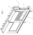
- a component 1 comprises a frame made of composite profiles 2, which is mounted in a building opening.
- the window frame can be surrounded all the way around by masonry or can be formed as a mullion-transom construction.
- a surface element 3 in the form of an insulating glass pane or another plate-shaped component is arranged in the frame, the surface element 3 optionally being fixed to a wing or directly to the composite profile 2 of the frame.
- FIG. 2 a sectional view through a vertical composite profile 2 of a frame is shown.
- the composite profile 2 comprises an inner shell 10, which can be made of metal or wood and is connected to an outer shell 14 via an insulating section 11.
- the insulating section 11 can comprise one or more insulating webs 12 made of plastic and can also be filled with one or more insulating bodies 13.
- the outer shell 14 is made of metal, in particular an extruded aluminum profile.
- the outer shell 14 is designed as an angular profile and comprises a first leg 15, which is oriented essentially parallel to the surface element 3, and a second leg 16, which protrudes outward essentially perpendicularly from the first leg 15.
- Fastening webs are formed on the first leg 15 on the side facing the insulating section 11.
- the first insulating web 15 can be single-walled or double-walled and optionally comprise one or more hollow chambers.
- the basic shape of the insulating web 15, apart from such hollow chambers, fastening webs or fitting grooves, is aligned parallel to the surface element 3.
- the second leg 16, which projects vertically from the first leg 15, can likewise be single or double-walled and have one or more hollow chambers.
- 16 attachment webs, grooves or other profiles can also be formed on the second leg.
- a guide device 32 for a sun protection 30 is formed on the outer shell 14.
- the sun protection 30 can be designed as a textile curtain or lamella curtain which has movable guide elements 31 on opposite sides, which are held movable in a groove in the guide device 32.
- the guide device comprises a strip-shaped profile which, with a first hook-shaped fastening web 33, engages around an outer web on the second leg 16 in a U-shape.
- two fastening webs 34 are supported on the first leg 15 and secured by holding webs on the first leg 15 against displacement in the plane of the surface element.
- the strip-shaped profile can be clamped or latched to the outer shell 14, with an additional screwing optionally being possible. In any case, forces can already be absorbed by the second leg 16 by fixing the guide device 32 and, in addition, a gap formation is avoided in the region of the second leg 16, since this is formed integrally with the outer shell 14.
- FIG 3 the composite profile is shown without the sun protection 30.
- the composite profile 2 can be inserted into a masonry or a supporting structure in a window frame, the second leg 16 being able to be provided with sealing means on the side facing away from the sun protection 30 in order to form a first sealing level.
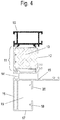
- FIG 4 A modified embodiment of a composite profile is shown, in which a modified outer shell 14 'is fixed to the insulating section 11.
- the outer shell 14 ' is angularly formed with a first leg 15 and a second leg 16, wherein an angled guide web 17 is additionally formed on the second leg 16, which has an inwardly projecting web 18.
- a further guide web 20 is protruding, so that an undercut groove 19 is formed on the second leg 16, on which a sun protection 30 with movable guide elements 31 can be mounted directly.
- FIG 2 Shown two-part design of the leg 16 with the guide device 32 is in Figure 4 formed in one piece, so that the outer shell 14 'has an integrally formed guide device, in particular a groove 19 or guide groove or guide webs, which are used for mounting a sun protection.
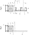
- FIG. 5 and 6 A third embodiment of a composite profile is shown, in which an outer shell 14 is connected to an inner shell 10 via an insulating section 11.
- the outer shell 14 has a modified second leg 16 ', which has a greater length than in the embodiment of FIG Figures 2 and 3 ,
- a guide device 32 can be mounted on the second leg 16 ′, which has a first guide groove for sun protection 30 and a second groove 35 for fall protection 40.
- the guide device 32 is designed as a strip-shaped profile, which is fixed with a hook-shaped fastening web 33 to an outwardly projecting web of the second leg 16 ', and in addition two fastening webs 34 are supported on the first leg 15 and secured against displacement, as is also the case in Figure 2 is shown.
- the component can also be used with a window frame with floor-to-ceiling windows, which on the outside with a Fall protection 40 must be provided.
- the fall protection 40 can be designed as a glass pane, grating or surface element which is held on the outer shell 14 by the guide device 32.
- the sun protection 30 is then held on the outside of the fall protection 40 so that it can be moved via the guide elements 31.
- the guiding device 32 can be formed integrally with the outer shell 14 in order to reduce the number of components.
- FIG. 7 and 8 A fourth embodiment of a composite profile is shown, in which a modified outer shell 44 is fixed to an insulating section 11, which in turn is connected to an inner shell 10.
- the outer shell 44 comprises two interconnected angle profiles, which are T-shaped in cross section.
- a first angle profile comprises a first leg 45, which extends parallel to a surface element, and a second leg 46, which projects essentially perpendicularly outwards.
- the second angle profile comprises a third leg 47, which is aligned parallel to a surface element, and the second leg 46.
- Fastening webs 33 are provided on the strip-shaped profile, which are inserted into a groove on the outside of the second leg 46, and fastening webs 34 are also provided on the guide device 32 ′ and are supported on the legs 45 and 47.
- the guide device 32 ′ has an undercut groove on opposite sides, into which movable guide elements 31 of a sun protection 30 are inserted. In this embodiment too, it is possible to provide the guide device 32 ′ with two grooves arranged next to one another, as shown in FIG Figure 6 is shown. In addition, the guide device 32 ′ can optionally also be formed integrally with the second leg 46.
Landscapes
- Engineering & Computer Science (AREA)
- Structural Engineering (AREA)
- Civil Engineering (AREA)
- Architecture (AREA)
- Physics & Mathematics (AREA)
- Electromagnetism (AREA)
- Securing Of Glass Panes Or The Like (AREA)
Abstract
Description
- Die vorliegende Erfindung betrifft ein Bauelement, beispielsweise ein Fenster, eine Tür, eine Fassade, zur Montage an einer Gebäudeöffnung, mit einem Blendrahmen, in dem ein Flächenelement mittelbar oder unmittelbar gehalten ist, wobei der Blendrahmen aus mindestens einem Verbundprofil mit einer Innenschale, einer Außenschale und einem die Innenschale und die Außenschale verbindenden Isolierabschnitt gebildet ist.
- Die
US 2015/0027059 offenbart ein Fenster mit einer integral ausgebildeten Führung für einen Behang, der an gegenüberliegenden Seiten in einer nutförmigen Aufnahme verfahrebar ist. - Die
EP 2 436 848 B1 offenbart eine Tragwerkkonstruktion, bei der an einer Pfosten-Riegel-Konstruktion ein hervorstehendes Tragprofil an einer Adapterschiene fixiert ist, die an einer Pfosten-Riegel-Konstruktion festgelegt ist. Zur Montage solcher hervorstehender Tragprofile dienen meist Schraubverbindungen. Bei nachträglich angeschraubten Tragprofilen bilden sich daher Fugen an dem Übergang zwischen Tragprofil und einem Profil der Tragkonstruktion aus. Gerade bei Montage eines Sonnenschutzes werden häufig eine Vielzahl von Führungsprofilen an einem Blendrahmen montiert, wobei das Verschrauben solcher Führungsprofile in der Montage aufwändig ist und zudem wegen der Fugenbildung optisch nachteilig ist. - Es ist daher Aufgabe der vorliegenden Erfindung, ein Bauelement zur Montage an einer Gebäudeöffnung zu schaffen, an dem auf einfache Weise an einer Außenseite ein Sonnenschutz oder andere Funktionselemente montiert werden können.
- Diese Aufgabe wird mit einem Bauelement mit den Merkmalen des Anspruches 1 gelöst.
- Bei dem erfindungsgemäßen Bauelement weist der Blendrahmen mindestens ein Verbundprofil mit einer Außenschale auf, das ein Winkelprofil umfasst und einen ersten Schenkel aufweist, der an dem Isolierabschnitt festgelegt ist und im Wesentlichen parallel zu dem Flächenelement ausgerichtet ist, und einen zweiten Schenkel, der auf der von dem Isolierabschnitt abgewandten Seite hervorsteht und an dem mindestens eine Führungs- und/oder Haltevorrichtung vorgesehen ist. Der zweite Schenkel der Außenschale steht somit von dem Flächenelement hervor und kann zur Befestigung und Führung von Bauteilen eingesetzt werden, insbesondere können an dem zweiten Schenkel ein Sonnenschutz, eine Absturzsicherung oder weitere Bauteile montiert werden. Der zweite Schenkel bildet somit ein vorgefertigtes Hilfsmittel aus, um eine Führungs- und/oder Haltevorrichtung zu montieren.
- Erfindungsgemäß ist an dem zweiten Schenkel eine Haltevorrichtung für eine Absturzsicherung vorgesehen. Eine solche Absturzsicherung ist beispielsweise notwendig, wenn an dem Blendrahmen ein bodentiefer Flügel vorgesehen wird, so dass über eine gewisse Höhe des Blendrahmens eine Absturzsicherung vorgesehen werden muss, die als durchsturzsicheres Glas, Gitter oder sonstiges Flächenelement ausgebildet sein kann. Eine solche Absturzsicherung kann ebenfalls an dem zweiten Schenkel der Außenschale montiert werden.
- Der zweite Schenkel erstreckt sich vorzugsweise in einem rechten Winkel von dem ersten Schenkel. Dabei kann jeder Schenkel wahlweise ein- oder mehrwandig ausgebildet sein und optional zur Erhöhung der Stabilität eine Hohlkammer aufweisen. Zudem können an den Stegen Befestigungsstege oder andere Profilierungen integral ausgebildet sein, ohne dass die Grundform der Außenschale mit der Winkelform geändert wird.
- Der Blendrahmen umfasst vorzugsweise an gegenüberliegenden vertikalen Seiten jeweils ein Verbundprofil mit einer Außenschale, die ein Winkelprofil aufweist. Die horizontalen Verbundprofile an der Unterseite und der Oberseite des Blendrahmens können optional auch ein Verbundprofil mit Winkelprofil aufweisen, vorzugweise ist zumindest das Verbundprofil an der Oberseite mit einer glatten Außenfläche ohne einen zweiten Schenkel ausgebildet. Zur Führung eines Sonnenschutzes können beispielsweise nur die beiden vertikalen Verbundprofile eine Außenschale mit einem Winkelprofil aufweisen. An dem zweiten Schenkel kann dann ein Sonnenschutz montiert werden, wobei hierfür die Führungs- und/oder Haltevorrichtung ein leistenförmiges Profil umfassen kann, das an dem zweiten Schenkel fixiert ist. Das Profil kann dann klemmend und/oder rastend an dem zweiten Schenkel fixiert werden, wobei an dem zweiten Schenkel entsprechende Profilierungen oder Befestigungsstege vorgesehen sein können, um das leistenförmige Profil vorfixieren oder fixieren zu können. Alternativ kann an dem zweiten Schenkel auch eine Führungs- oder Haltevorrichtung integral ausgebildet sein. Hierfür können an dem zweiten Schenkel Nuten, Haltestege oder andere Profilierungen vorgesehen sein, an denen ein Sonnenschutz, beispielsweise mit Führungselementen- unmittelbar montiert werden kann.
- In einer weiteren Ausgestaltung ist die Außenschale T-förmig ausgebildet und umfasst somit zwei winkelförmige Abschnitte, wobei an dem hervorstehenden zweiten Schenkel vorzugsweise auf gegenüberliegenden Seiten eine Führungs- oder Haltevorrichtung festgelegt ist. Dann kann der zweiten Schenkel der Außenschale genutzt werden, um an gegenüberliegenden Seiten einen Sonnenschutz und/oder eine Absturzsicherung vorzusehen.
- Die Erfindung wird nachfolgend anhand mehrerer Ausführungsbeispiele mit Bezug auf die beigefügten Zeichnungen näher erläutert. Es zeigen:
- Figur 1
- eine perspektivische Ansicht eines Bauelementes in einer montierten Position;
- Figuren 2 und 3
- zwei Schnittansichten durch ein Verbundprofil für ein erfindungsgemäßes Bauelement in einer ersten Ausführungsform;
- Figur 4
- eine Schnittansicht durch ein Verbundprofil gemäß einer zweiten Ausführungsform;
- Figuren 5 und 6
- zwei Schnittansichten durch ein Verbundprofil einer dritten Ausführungsform, und
- Figuren 7 und 8
- zwei Schnittansichten durch ein Verbundprofil gemäß einer vierten Ausführungsform.
- Ein Bauelement 1 umfasst einen aus Verbundprofilen 2 hergestellten Blendrahmen, der in einer Gebäudeöffnung montiert ist. Dabei kann der Blendrahmen umlaufend von einem Mauerwerk umgeben sein oder als Pfosten-Riegel-Konstruktion gebildet sein. In dem Blendrahmen ist ein Flächenelement 3 in Form einer Isolierglasscheibe oder eines anderen plattenförmigen Bauteils angeordnet, wobei das Flächenelement 3 wahlweise an einem Flügel oder unmittelbar an dem Verbundprofil 2 des Blendrahmens fixiert sein kann. An dem Flächenelement 3 sind an der Außenseite zwei vertikale Führungen 4 für einen Sonnenschutz 5 vorgesehen, wobei der Sonnenschutz 5 entlang der beiden Führungen 4 verfahrbar ist.
- In
Figur 2 ist eine Schnittansicht durch ein vertikales Verbundprofil 2 eines Blendrahmens gezeigt. Das Verbundprofil 2 umfasst eine Innenschale 10, die aus Metall oder Holz hergestellt sein kann und über einen Isolierabschnitt 11 mit einer Außenschale 14 verbunden ist. Der Isolierabschnitt 11 kann ein oder mehrere Isolierstege 12 aus Kunststoff umfassen und zudem mit einem oder mehreren Isolierkörpern 13 gefüllt sein. Die Außenschale 14 besteht aus Metall, insbesondere aus einem extrudierten Aluminiumprofil. - Die Außenschale 14 ist als Winkelprofil ausgebildet und umfasst einen ersten Schenkel 15, der im Wesentlichen parallel zu dem Flächenelement 3 ausgerichtet ist, und einen zweiten Schenkel 16, der im Wesentlichen senkrecht von dem ersten Schenkel 15 nach außen hervorsteht. An dem ersten Schenkel 15 sind auf der zu dem Isolierabschnitt 11 gewandten Seite Befestigungsstege ausgebildet. Der erste Isoliersteg 15 kann einwandig oder doppelwandig ausgebildet sein und optional eine oder mehrere Hohlkammern umfassen. In jedem Fall ist die Grundform des Isoliersteges 15, abgesehen von solchen Hohlkammern, Befestigungsstegen oder Beschlagsnuten, parallel zu dem Flächenelement 3 ausgerichtet. Der von dem ersten Schenkel 15 senkrecht hervorstehende zweite Schenkel 16 kann ebenfalls ein- oder doppelwandig ausgebildet sein und eine oder mehrere Hohlkammern aufweisen. Zudem können auch an dem zweiten Schenkel 16 Befestigungsstege, Nuten oder andere Profilierungen ausgebildet sein.
- In
Figur 2 ist an der Außenschale 14 eine Führungsvorrichtung 32 für einen Sonnenschutz 30 ausgebildet. Der Sonnenschutz 30 kann als textiler Behang oder Lamellenbehang ausgebildet sein, der an gegenüberliegenden Seiten Verfahrbare Führungselemente 31 aufweist, die in einer Nut der Führungsvorrichtung 32 verfahrbar gehalten sind. Die Führungsvorrichtung umfasst ein leistenförmiges Profil, das mit einem ersten hakenförmigen Befestigungssteg 33 einen äußeren Steg an dem zweiten Schenkel 16 U-förmig umgreift. Zudem sind zwei Befestigungsstege 34 an dem ersten Schenkel 15 abgestützt und durch Haltestege an dem ersten Schenkel 15 gegen ein Verschieben in der Ebene des Flächenelementes gesichert. Das leistenförmige Profil kann klemmend oder rastend an der Außenschale 14 festgelegt sein, wobei optional auch ein zusätzliches Verschrauben möglich ist. In jedem Fall können von dem zweiten Schenkel 16 schon Kräfte durch die Fixierung der Führungsvorrichtung 32 aufgenommen werden, und zudem wird im Bereich des zweiten Schenkels 16 eine Fugenbildung vermieden, da dieser integral mit der Außenschale 14 ausgebildet ist. - In
Figur 3 ist das Verbundprofil ohne den Sonnenschutz 30 dargestellt. Das Verbundprofil 2 kann in einem Blendrahmen in ein Mauerwerk oder eine Tragkonstruktion eingesetzt werden, wobei der zweite Schenkel 16 auf der zu dem Sonnenschutz 30 abgewandten Seite mit Dichtmitteln versehen sein kann, um eine erste Dichtebene auszubilden. - In
Figur 4 ist eine modifizierte Ausgestaltung eines Verbundprofils gezeigt, bei der eine geänderte Außenschale 14' an dem Isolierabschnitt 11 festgelegt ist. Die Außenschale 14' ist winkelförmig mit einem ersten Schenkel 15 und einem zweiten Schenkel 16 ausgebildet, wobei zusätzlich an dem zweiten Schenkel 16 ein abgewinkelter Führungssteg 17 angeformt ist, der einen nach innen ragenden Steg 18 aufweist. An dem ersten Schenkel 15 ist ein weiterer Führungssteg 20 hervorstehend ausgebildet, so dass eine hinterschnittene Nut 19 an dem zweiten Schenkel 16 ausgebildet ist, an der unmittelbar ein Sonnenschutz 30 mit verfahrbaren Führungselementen 31 montiert werden kann. Die inFigur 2 gezeigte zweiteilige Ausgestaltung des Schenkels 16 mit der Führungsvorrichtung 32 ist inFigur 4 einteilig ausgebildet, so dass die Außenschale 14' eine integral ausgebildete Führungsvorrichtung besitzt, insbesondere eine Nut 19 oder Führungsnut oder Führungsstege, die zur Montage eines Sonnenschutzes dienen. - In den
Figuren 5 und 6 ist eine dritte Ausführungsform eines Verbundprofils gezeigt, bei dem eine Außenschale 14 über einen Isolierabschnitt 11 mit einer Innenschale 10 verbunden ist. Die Außenschale 14 besitzt einen modifizierten zweiten Schenkel 16', der eine größere Länge besitzt als bei dem Ausführungsbeispiel derFiguren 2 und 3 . Dadurch kann eine Führungsvorrichtung 32 an dem zweiten Schenkel 16' montiert werden, die eine erste Führungsnut für einen Sonnenschutz 30 und eine zweite Nut 35 für eine Absturzsicherung 40 aufweist. Die Führungsvorrichtung 32 ist als leistenförmiges Profil ausgebildet, das mit einem hakenförmigen Befestigungssteg 33 an einem nach außen ragenden Steg des zweiten Schenkels 16' fixiert ist, und zudem sind zwei Befestigungsstege 34 an dem ersten Schenkel 15 abgestützt und gegen ein Verschieben gesichert, wie dies auch inFigur 2 gezeigt ist. Durch die Ausgestaltung derFiguren 5 und 6 kann das Bauelement auch mit einem Blendrahmen mit bodentiefen Fenstern eingesetzt werden, die an der Außenseite mit einer Absturzsicherung 40 versehen werden müssen. Die Absturzsicherung 40 kann als Glasscheibe, Gitter oder Flächenelement ausgebildet sein, das über die Führungsvorrichtung 32 an der Außenschale 14 gehalten ist. Auf der Außenseite der Absturzsicherung 40 ist dann der Sonnenschutz 30 verfahrbar über die Führungselemente 31 gehalten. Auch bei dem Ausführungsbeispiel derFiguren 5 und 6 kann die Führungsvorrichtung 32 integral mit der Außenschale 14 ausgebildet sein, um die Anzahl der Bauteile zu reduzieren. - In den
Figuren 7 und 8 ist eine vierte Ausführungsform eines Verbundprofils gezeigt, bei dem eine modifizierte Außenschale 44 an einem Isolierabschnitt 11 fixiert ist, der wiederum mit einer Innenschale 10 verbunden ist. - Die Außenschale 44 umfasst zwei miteinander verbundene Winkelprofile, die im Querschnitt T-förmig ausgebildet sind. Ein erstes Winkelprofil umfasst einen ersten Schenkel 45, der sich parallel zu einem Flächenelement erstreckt, und einen zweiten Schenkel 46, der im Wesentlichen senkrecht nach außen hervorsteht. Das zweite Winkelprofil umfasst einen dritten Schenkel 47, der parallel zu einem Flächenelement ausgerichtet ist, und den zweiten Schenkel 46. Durch diese Ausgestaltung der Außenschale 46 kann an gegenüberliegenden Seiten des hervorstehenden zweiten Schenkels eine Haltevorrichtung 32' vorgesehen werden, die in dem dargestellten Ausführungsbeispiel als einteiliges Profil ausgebildet ist, das von außen auf den zweiten Schenkel 46 aufgesteckt wird. An dem leistenförmigen Profil sind Befestigungsstege 33 vorgesehen, die in eine Nut an der Außenseite des zweiten Schenkels 46 eingefügt sind, und zudem sind an der Führungsvorrichtung 32' Befestigungsstege 34 vorgesehen, die an den Schenkeln 45 und 47 abgestützt sind. Die Führungsvorrichtung 32' besitzt an gegenüberliegenden Seiten jeweils eine hinterschnittene Nut, in die verfahrbare Führungselemente 31 eines Sonnenschutzes 30 eingefügt sind. Auch bei dieser Ausführungsform ist es möglich, die Führungsvorrichtung 32' mit zwei nebeneinander angeordneten Nuten zu versehen, wie dies in
Figur 6 gezeigt ist. Zudem kann die Führungsvorrichtung 32' optional auch integral mit dem zweiten Schenkel 46 ausgebildet sein. -
- 1
- Bauelement
- 2
- Verbundprofil
- 3
- Flächenelement
- 4
- Führung
- 5
- Sonnenschutz
- 10
- Innenschale
- 11
- Isolierabschnitt
- 12
- Isoliersteg
- 13
- Isolierkörper
- 14, 14'
- Außenschale
- 15
- Schenkel
- 16, 16'
- Schenkel
- 17
- Führungssteg
- 18
- Steg
- 19
- Nut
- 20
- Führungssteg
- 30
- Sonnenschutz
- 31
- Führungselement
- 32
- Führungsvorrichtung
- 32'
- Haltevorrichtung
- 33
- Befestigungssteg
- 34
- Befestigungssteg
- 35
- Nut
- 40
- Absturzsicherung
- 44
- Außenschale
- 45
- Schenkel
- 46
- Schenkel
- 47
- Schenkel
Claims (8)
- Bauelement zur Montage an einer Gebäudeöffnung, mit einem Blendrahmen, in dem ein Flächenelement (3) mittelbar oder unmittelbar gehalten ist, wobei der Blendrahmen aus mindestens einem Verbundprofil (2) mit einer Innenschale (10), einer Außenschale (14, 44) und einem die Innenschale (10) und die Außenschale (14, 44) verbindenden Isolierabschnitt (11) gebildet ist, dadurch gekennzeichnet, dass die Außenschale (14, 44) ein Winkelprofil umfasst, mit einem ersten Schenkel (15, 45), der an dem Isolierabschnitt (11) festgelegt ist, und sich im Wesentlichen parallel zu dem Flächenelement (3) erstreckt, und einem zweiten Schenkel (16, 46), der auf der von dem Isolierabschnitt (11) abgewandten Seite hervorsteht und an dem mindestens eine Führungs- und/oder Haltevorrichtung (17, 32) festgelegt ist, wobei an dem zweiten Schenkel (16, 46) eine Haltevorrichtung (32) für eine Absturzsicherung (40) vorgesehen ist.
- Bauelement nach Anspruch 1, dadurch gekennzeichnet, dass der zweite Schenkel (16, 46) im Wesentlichen in einem rechten Winkel zu dem ersten Schenkel (15, 45) ausgerichtet ist.
- Bauelement nach Anspruch 1 oder 2, dadurch gekennzeichnet, dass der Blendrahmen an gegenüberliegenden vertikalen Seiten jeweils ein Verbundprofil (2) mit einer Außenschale (14, 44) als Winkelprofil aufweist.
- Bauelement nach einem der Ansprüche 1 bis 3, dadurch gekennzeichnet, dass an dem zweiten Schenkel (16, 46) eine Führungsvorrichtung (32) für einen verfahrbaren Sonnenschutz (30) vorgesehen ist.
- Bauelement nach einem der vorhergehenden Ansprüche, dadurch gekennzeichnet, dass die Führungs- oder Haltevorrichtung (32) ein leistenförmiges Profil umfasst, das an dem zweiten Schenkel (16, 46) fixiert ist.
- Bauelement nach Anspruch 5, dadurch gekennzeichnet, dass das leistenförmige Profil klemmend und/oder rastend an dem zweiten Schenkel (16, 46) fixiert ist.
- Bauelement nach einem der Ansprüche 1 bis 4, dadurch gekennzeichnet, dass die Führungs- oder Haltevorrichtung (17) integral mit dem zweiten Schenkel (16) ausgebildet ist.
- Bauelement nach einem der vorhergehenden Ansprüche, dadurch gekennzeichnet, dass die Außenschale (44) T-förmig ausgebildet ist und an dem hervorstehenden zweiten Schenkel (46) auf gegenüberliegenden Seiten eine Führungs- oder Haltevorrichtung (32) festgelegt ist.
Priority Applications (1)
| Application Number | Priority Date | Filing Date | Title |
|---|---|---|---|
| PL19175408T PL3591158T3 (pl) | 2018-07-04 | 2019-05-20 | Element konstrukcyjny |
Applications Claiming Priority (1)
| Application Number | Priority Date | Filing Date | Title |
|---|---|---|---|
| DE202018103814.1U DE202018103814U1 (de) | 2018-07-04 | 2018-07-04 | Bauelement |
Publications (2)
| Publication Number | Publication Date |
|---|---|
| EP3591158A1 true EP3591158A1 (de) | 2020-01-08 |
| EP3591158B1 EP3591158B1 (de) | 2021-10-13 |
Family
ID=66625096
Family Applications (1)
| Application Number | Title | Priority Date | Filing Date |
|---|---|---|---|
| EP19175408.4A Active EP3591158B1 (de) | 2018-07-04 | 2019-05-20 | Bauelement |
Country Status (4)
| Country | Link |
|---|---|
| EP (1) | EP3591158B1 (de) |
| DE (1) | DE202018103814U1 (de) |
| ES (1) | ES2897442T3 (de) |
| PL (1) | PL3591158T3 (de) |
Families Citing this family (1)
| Publication number | Priority date | Publication date | Assignee | Title |
|---|---|---|---|---|
| FR3151052A1 (fr) * | 2023-07-13 | 2025-01-17 | Lapeyre | Cadre de dormant dont les montants sont equipes d’un profile de tapee |
Citations (3)
| Publication number | Priority date | Publication date | Assignee | Title |
|---|---|---|---|---|
| EP2436848A2 (de) | 2010-10-01 | 2012-04-04 | SCHÜCO International KG | Tragwerkkonstruktion |
| US20150027059A1 (en) | 2012-05-16 | 2015-01-29 | Xianfeng LU | Integrated multi-function window |
| CN205330484U (zh) * | 2016-01-25 | 2016-06-22 | 南京二十六度建筑节能工程有限公司 | 一种抗强风外遮阳一体化窗 |
Family Cites Families (4)
| Publication number | Priority date | Publication date | Assignee | Title |
|---|---|---|---|---|
| DE29702911U1 (de) * | 1997-02-19 | 1997-06-19 | Woschko, Emil, 74182 Obersulm | Anordnung zur Anbringung einer Führungsschiene für Rolläden an einem Blendrahmen |
| DE10060345A1 (de) * | 2000-12-04 | 2002-06-20 | Blaurock Gmbh | Führungseinrichtung für Rolladen |
| CN202299941U (zh) * | 2011-09-14 | 2012-07-04 | 湖南湘联节能科技股份有限公司 | 一种三位一体集成卷窗的竖外框型材 |
| DE202017102736U1 (de) * | 2017-05-08 | 2017-06-16 | Warema Renkhoff Se | Führungsschiene für eine Sonnenschutzanlage und entsprechende Sonnenschutzanlage |
-
2018
- 2018-07-04 DE DE202018103814.1U patent/DE202018103814U1/de active Active
-
2019
- 2019-05-20 ES ES19175408T patent/ES2897442T3/es active Active
- 2019-05-20 EP EP19175408.4A patent/EP3591158B1/de active Active
- 2019-05-20 PL PL19175408T patent/PL3591158T3/pl unknown
Patent Citations (3)
| Publication number | Priority date | Publication date | Assignee | Title |
|---|---|---|---|---|
| EP2436848A2 (de) | 2010-10-01 | 2012-04-04 | SCHÜCO International KG | Tragwerkkonstruktion |
| US20150027059A1 (en) | 2012-05-16 | 2015-01-29 | Xianfeng LU | Integrated multi-function window |
| CN205330484U (zh) * | 2016-01-25 | 2016-06-22 | 南京二十六度建筑节能工程有限公司 | 一种抗强风外遮阳一体化窗 |
Also Published As
| Publication number | Publication date |
|---|---|
| EP3591158B1 (de) | 2021-10-13 |
| ES2897442T3 (es) | 2022-03-01 |
| DE202018103814U1 (de) | 2019-10-11 |
| PL3591158T3 (pl) | 2022-02-07 |
Similar Documents
| Publication | Publication Date | Title |
|---|---|---|
| EP1352134B1 (de) | Riegel-pfosten-konstruktion | |
| EP0945577A2 (de) | Vorrichtung zum Abstützen von Fenster- oder Türrahmen an der Begrenzung einer Wandöffnung | |
| EP2666948A1 (de) | Rahmenanordnung für ein Sektionaltorpaneel | |
| EP3591158B1 (de) | Bauelement | |
| EP3770372B1 (de) | Kasten zur aufnahme eines rollladens oder eines sonnenschutzes und fenster oder tür | |
| DE29816780U1 (de) | Vorrichtung zum Abstützen von Fenster- oder Türrahmen an der Begrenzung einer Wandöffnung | |
| DE4000969A1 (de) | Anordnung zum befestigen einer gebaeudeplatte an einer gebaeudewand | |
| EP1437478A2 (de) | Wärmegedämmtes Verbundprofil | |
| DE102017100617B4 (de) | Pfosten-Riegel-Konstruktion | |
| DE20100618U1 (de) | Rahmenprofil | |
| DE2642746C3 (de) | Aus Schaumstoff mit eingelagerten metallenen Hohlprofilen bestehender Rahmen fur Fenster | |
| DE202016105087U1 (de) | Halteschiene für einen französischen Balkon sowie Haltevorrichtung und Anordnung dafür | |
| DE29910027U1 (de) | Pfosten-Riegel-System für mit Ausfachungen versehene Gebäudefassaden | |
| EP3770373A1 (de) | Montageeinheit und verfahren zur montage eines kastens zur aufnahme eines rollladens oder eines sonnenschutzes an einem blendrahmen | |
| DE29620668U1 (de) | Profilelement zur Festlegung einer Festverglasung | |
| EP3879061B1 (de) | Schiebetür und bausatz für eine schiebetür | |
| DE20118311U1 (de) | Kollektorfassade | |
| DE202010016979U1 (de) | Lichtband und Hallenwand mit einem Lichtband | |
| EP4361369A1 (de) | Fassadenkonstruktion und verfahren zur montage einer fassadenkonstruktion | |
| DE202023101422U1 (de) | Türrahmen, und Glastüranlage | |
| DE102024101452A1 (de) | Profilverbindung | |
| DE202010008692U1 (de) | Tragwerkkonstruktion | |
| DE102022115118A1 (de) | Tragprofilkonstruktion | |
| DE202007005388U1 (de) | Rahmenkonstruktion für Fenster und/oder Türen | |
| DE102008029073B3 (de) | Rahmenprofil für Garagentore und Garagentorrahmen |
Legal Events
| Date | Code | Title | Description |
|---|---|---|---|
| PUAI | Public reference made under article 153(3) epc to a published international application that has entered the european phase |
Free format text: ORIGINAL CODE: 0009012 |
|
| STAA | Information on the status of an ep patent application or granted ep patent |
Free format text: STATUS: THE APPLICATION HAS BEEN PUBLISHED |
|
| AK | Designated contracting states |
Kind code of ref document: A1 Designated state(s): AL AT BE BG CH CY CZ DE DK EE ES FI FR GB GR HR HU IE IS IT LI LT LU LV MC MK MT NL NO PL PT RO RS SE SI SK SM TR |
|
| AX | Request for extension of the european patent |
Extension state: BA ME |
|
| STAA | Information on the status of an ep patent application or granted ep patent |
Free format text: STATUS: REQUEST FOR EXAMINATION WAS MADE |
|
| 17P | Request for examination filed |
Effective date: 20200626 |
|
| RBV | Designated contracting states (corrected) |
Designated state(s): AL AT BE BG CH CY CZ DE DK EE ES FI FR GB GR HR HU IE IS IT LI LT LU LV MC MK MT NL NO PL PT RO RS SE SI SK SM TR |
|
| STAA | Information on the status of an ep patent application or granted ep patent |
Free format text: STATUS: EXAMINATION IS IN PROGRESS |
|
| 17Q | First examination report despatched |
Effective date: 20210507 |
|
| GRAP | Despatch of communication of intention to grant a patent |
Free format text: ORIGINAL CODE: EPIDOSNIGR1 |
|
| STAA | Information on the status of an ep patent application or granted ep patent |
Free format text: STATUS: GRANT OF PATENT IS INTENDED |
|
| INTG | Intention to grant announced |
Effective date: 20210729 |
|
| GRAS | Grant fee paid |
Free format text: ORIGINAL CODE: EPIDOSNIGR3 |
|
| GRAA | (expected) grant |
Free format text: ORIGINAL CODE: 0009210 |
|
| STAA | Information on the status of an ep patent application or granted ep patent |
Free format text: STATUS: THE PATENT HAS BEEN GRANTED |
|
| AK | Designated contracting states |
Kind code of ref document: B1 Designated state(s): AL AT BE BG CH CY CZ DE DK EE ES FI FR GB GR HR HU IE IS IT LI LT LU LV MC MK MT NL NO PL PT RO RS SE SI SK SM TR |
|
| REG | Reference to a national code |
Ref country code: GB Ref legal event code: FG4D Free format text: NOT ENGLISH |
|
| REG | Reference to a national code |
Ref country code: CH Ref legal event code: EP |
|
| REG | Reference to a national code |
Ref country code: DE Ref legal event code: R096 Ref document number: 502019002488 Country of ref document: DE |
|
| REG | Reference to a national code |
Ref country code: IE Ref legal event code: FG4D Free format text: LANGUAGE OF EP DOCUMENT: GERMAN |
|
| REG | Reference to a national code |
Ref country code: AT Ref legal event code: REF Ref document number: 1438319 Country of ref document: AT Kind code of ref document: T Effective date: 20211115 |
|
| REG | Reference to a national code |
Ref country code: LT Ref legal event code: MG9D |
|
| REG | Reference to a national code |
Ref country code: NL Ref legal event code: MP Effective date: 20211013 |
|
| REG | Reference to a national code |
Ref country code: ES Ref legal event code: FG2A Ref document number: 2897442 Country of ref document: ES Kind code of ref document: T3 Effective date: 20220301 |
|
| PG25 | Lapsed in a contracting state [announced via postgrant information from national office to epo] |
Ref country code: RS Free format text: LAPSE BECAUSE OF FAILURE TO SUBMIT A TRANSLATION OF THE DESCRIPTION OR TO PAY THE FEE WITHIN THE PRESCRIBED TIME-LIMIT Effective date: 20211013 Ref country code: LT Free format text: LAPSE BECAUSE OF FAILURE TO SUBMIT A TRANSLATION OF THE DESCRIPTION OR TO PAY THE FEE WITHIN THE PRESCRIBED TIME-LIMIT Effective date: 20211013 Ref country code: FI Free format text: LAPSE BECAUSE OF FAILURE TO SUBMIT A TRANSLATION OF THE DESCRIPTION OR TO PAY THE FEE WITHIN THE PRESCRIBED TIME-LIMIT Effective date: 20211013 Ref country code: BG Free format text: LAPSE BECAUSE OF FAILURE TO SUBMIT A TRANSLATION OF THE DESCRIPTION OR TO PAY THE FEE WITHIN THE PRESCRIBED TIME-LIMIT Effective date: 20220113 |
|
| PG25 | Lapsed in a contracting state [announced via postgrant information from national office to epo] |
Ref country code: IS Free format text: LAPSE BECAUSE OF FAILURE TO SUBMIT A TRANSLATION OF THE DESCRIPTION OR TO PAY THE FEE WITHIN THE PRESCRIBED TIME-LIMIT Effective date: 20220213 Ref country code: SE Free format text: LAPSE BECAUSE OF FAILURE TO SUBMIT A TRANSLATION OF THE DESCRIPTION OR TO PAY THE FEE WITHIN THE PRESCRIBED TIME-LIMIT Effective date: 20211013 Ref country code: PT Free format text: LAPSE BECAUSE OF FAILURE TO SUBMIT A TRANSLATION OF THE DESCRIPTION OR TO PAY THE FEE WITHIN THE PRESCRIBED TIME-LIMIT Effective date: 20220214 Ref country code: NO Free format text: LAPSE BECAUSE OF FAILURE TO SUBMIT A TRANSLATION OF THE DESCRIPTION OR TO PAY THE FEE WITHIN THE PRESCRIBED TIME-LIMIT Effective date: 20220113 Ref country code: NL Free format text: LAPSE BECAUSE OF FAILURE TO SUBMIT A TRANSLATION OF THE DESCRIPTION OR TO PAY THE FEE WITHIN THE PRESCRIBED TIME-LIMIT Effective date: 20211013 Ref country code: LV Free format text: LAPSE BECAUSE OF FAILURE TO SUBMIT A TRANSLATION OF THE DESCRIPTION OR TO PAY THE FEE WITHIN THE PRESCRIBED TIME-LIMIT Effective date: 20211013 Ref country code: HR Free format text: LAPSE BECAUSE OF FAILURE TO SUBMIT A TRANSLATION OF THE DESCRIPTION OR TO PAY THE FEE WITHIN THE PRESCRIBED TIME-LIMIT Effective date: 20211013 Ref country code: GR Free format text: LAPSE BECAUSE OF FAILURE TO SUBMIT A TRANSLATION OF THE DESCRIPTION OR TO PAY THE FEE WITHIN THE PRESCRIBED TIME-LIMIT Effective date: 20220114 |
|
| REG | Reference to a national code |
Ref country code: DE Ref legal event code: R097 Ref document number: 502019002488 Country of ref document: DE |
|
| PG25 | Lapsed in a contracting state [announced via postgrant information from national office to epo] |
Ref country code: SM Free format text: LAPSE BECAUSE OF FAILURE TO SUBMIT A TRANSLATION OF THE DESCRIPTION OR TO PAY THE FEE WITHIN THE PRESCRIBED TIME-LIMIT Effective date: 20211013 Ref country code: SK Free format text: LAPSE BECAUSE OF FAILURE TO SUBMIT A TRANSLATION OF THE DESCRIPTION OR TO PAY THE FEE WITHIN THE PRESCRIBED TIME-LIMIT Effective date: 20211013 Ref country code: RO Free format text: LAPSE BECAUSE OF FAILURE TO SUBMIT A TRANSLATION OF THE DESCRIPTION OR TO PAY THE FEE WITHIN THE PRESCRIBED TIME-LIMIT Effective date: 20211013 Ref country code: EE Free format text: LAPSE BECAUSE OF FAILURE TO SUBMIT A TRANSLATION OF THE DESCRIPTION OR TO PAY THE FEE WITHIN THE PRESCRIBED TIME-LIMIT Effective date: 20211013 Ref country code: DK Free format text: LAPSE BECAUSE OF FAILURE TO SUBMIT A TRANSLATION OF THE DESCRIPTION OR TO PAY THE FEE WITHIN THE PRESCRIBED TIME-LIMIT Effective date: 20211013 Ref country code: CZ Free format text: LAPSE BECAUSE OF FAILURE TO SUBMIT A TRANSLATION OF THE DESCRIPTION OR TO PAY THE FEE WITHIN THE PRESCRIBED TIME-LIMIT Effective date: 20211013 |
|
| PLBE | No opposition filed within time limit |
Free format text: ORIGINAL CODE: 0009261 |
|
| STAA | Information on the status of an ep patent application or granted ep patent |
Free format text: STATUS: NO OPPOSITION FILED WITHIN TIME LIMIT |
|
| 26N | No opposition filed |
Effective date: 20220714 |
|
| PG25 | Lapsed in a contracting state [announced via postgrant information from national office to epo] |
Ref country code: AL Free format text: LAPSE BECAUSE OF FAILURE TO SUBMIT A TRANSLATION OF THE DESCRIPTION OR TO PAY THE FEE WITHIN THE PRESCRIBED TIME-LIMIT Effective date: 20211013 |
|
| PG25 | Lapsed in a contracting state [announced via postgrant information from national office to epo] |
Ref country code: SI Free format text: LAPSE BECAUSE OF FAILURE TO SUBMIT A TRANSLATION OF THE DESCRIPTION OR TO PAY THE FEE WITHIN THE PRESCRIBED TIME-LIMIT Effective date: 20211013 |
|
| REG | Reference to a national code |
Ref country code: CH Ref legal event code: PL |
|
| PG25 | Lapsed in a contracting state [announced via postgrant information from national office to epo] |
Ref country code: MC Free format text: LAPSE BECAUSE OF FAILURE TO SUBMIT A TRANSLATION OF THE DESCRIPTION OR TO PAY THE FEE WITHIN THE PRESCRIBED TIME-LIMIT Effective date: 20211013 Ref country code: LU Free format text: LAPSE BECAUSE OF NON-PAYMENT OF DUE FEES Effective date: 20220520 Ref country code: LI Free format text: LAPSE BECAUSE OF NON-PAYMENT OF DUE FEES Effective date: 20220531 Ref country code: CH Free format text: LAPSE BECAUSE OF NON-PAYMENT OF DUE FEES Effective date: 20220531 |
|
| PG25 | Lapsed in a contracting state [announced via postgrant information from national office to epo] |
Ref country code: IE Free format text: LAPSE BECAUSE OF NON-PAYMENT OF DUE FEES Effective date: 20220520 |
|
| P01 | Opt-out of the competence of the unified patent court (upc) registered |
Effective date: 20230815 |
|
| GBPC | Gb: european patent ceased through non-payment of renewal fee |
Effective date: 20230520 |
|
| PG25 | Lapsed in a contracting state [announced via postgrant information from national office to epo] |
Ref country code: MK Free format text: LAPSE BECAUSE OF FAILURE TO SUBMIT A TRANSLATION OF THE DESCRIPTION OR TO PAY THE FEE WITHIN THE PRESCRIBED TIME-LIMIT Effective date: 20211013 Ref country code: CY Free format text: LAPSE BECAUSE OF FAILURE TO SUBMIT A TRANSLATION OF THE DESCRIPTION OR TO PAY THE FEE WITHIN THE PRESCRIBED TIME-LIMIT Effective date: 20211013 Ref country code: GB Free format text: LAPSE BECAUSE OF NON-PAYMENT OF DUE FEES Effective date: 20230520 |
|
| PG25 | Lapsed in a contracting state [announced via postgrant information from national office to epo] |
Ref country code: HU Free format text: LAPSE BECAUSE OF FAILURE TO SUBMIT A TRANSLATION OF THE DESCRIPTION OR TO PAY THE FEE WITHIN THE PRESCRIBED TIME-LIMIT; INVALID AB INITIO Effective date: 20190520 |
|
| PG25 | Lapsed in a contracting state [announced via postgrant information from national office to epo] |
Ref country code: MT Free format text: LAPSE BECAUSE OF FAILURE TO SUBMIT A TRANSLATION OF THE DESCRIPTION OR TO PAY THE FEE WITHIN THE PRESCRIBED TIME-LIMIT Effective date: 20211013 |
|
| PGFP | Annual fee paid to national office [announced via postgrant information from national office to epo] |
Ref country code: PL Payment date: 20250415 Year of fee payment: 7 Ref country code: DE Payment date: 20250422 Year of fee payment: 7 |
|
| PGFP | Annual fee paid to national office [announced via postgrant information from national office to epo] |
Ref country code: ES Payment date: 20250616 Year of fee payment: 7 |
|
| PGFP | Annual fee paid to national office [announced via postgrant information from national office to epo] |
Ref country code: BE Payment date: 20250606 Year of fee payment: 7 Ref country code: IT Payment date: 20250530 Year of fee payment: 7 |
|
| PGFP | Annual fee paid to national office [announced via postgrant information from national office to epo] |
Ref country code: FR Payment date: 20250415 Year of fee payment: 7 |
|
| PGFP | Annual fee paid to national office [announced via postgrant information from national office to epo] |
Ref country code: AT Payment date: 20250606 Year of fee payment: 7 |
|
| PG25 | Lapsed in a contracting state [announced via postgrant information from national office to epo] |
Ref country code: TR Free format text: LAPSE BECAUSE OF FAILURE TO SUBMIT A TRANSLATION OF THE DESCRIPTION OR TO PAY THE FEE WITHIN THE PRESCRIBED TIME-LIMIT Effective date: 20211013 |