EP3590818A1 - Schiffsladungsüberwachungsvorrichtung, schiffsladungsüberwachungsverfahren und schiffsladungsüberwachungsprogramm - Google Patents
Schiffsladungsüberwachungsvorrichtung, schiffsladungsüberwachungsverfahren und schiffsladungsüberwachungsprogramm Download PDFInfo
- Publication number
- EP3590818A1 EP3590818A1 EP18761760.0A EP18761760A EP3590818A1 EP 3590818 A1 EP3590818 A1 EP 3590818A1 EP 18761760 A EP18761760 A EP 18761760A EP 3590818 A1 EP3590818 A1 EP 3590818A1
- Authority
- EP
- European Patent Office
- Prior art keywords
- load
- hull
- posture
- acceleration
- observation
- Prior art date
- Legal status (The legal status is an assumption and is not a legal conclusion. Google has not performed a legal analysis and makes no representation as to the accuracy of the status listed.)
- Granted
Links
Images






Classifications
-
- B—PERFORMING OPERATIONS; TRANSPORTING
- B63—SHIPS OR OTHER WATERBORNE VESSELS; RELATED EQUIPMENT
- B63B—SHIPS OR OTHER WATERBORNE VESSELS; EQUIPMENT FOR SHIPPING
- B63B79/00—Monitoring properties or operating parameters of vessels in operation
-
- B—PERFORMING OPERATIONS; TRANSPORTING
- B63—SHIPS OR OTHER WATERBORNE VESSELS; RELATED EQUIPMENT
- B63B—SHIPS OR OTHER WATERBORNE VESSELS; EQUIPMENT FOR SHIPPING
- B63B43/00—Improving safety of vessels, e.g. damage control, not otherwise provided for
-
- B—PERFORMING OPERATIONS; TRANSPORTING
- B63—SHIPS OR OTHER WATERBORNE VESSELS; RELATED EQUIPMENT
- B63B—SHIPS OR OTHER WATERBORNE VESSELS; EQUIPMENT FOR SHIPPING
- B63B43/00—Improving safety of vessels, e.g. damage control, not otherwise provided for
- B63B43/18—Improving safety of vessels, e.g. damage control, not otherwise provided for preventing collision or grounding; reducing collision damage
- B63B43/20—Feelers
-
- B—PERFORMING OPERATIONS; TRANSPORTING
- B63—SHIPS OR OTHER WATERBORNE VESSELS; RELATED EQUIPMENT
- B63B—SHIPS OR OTHER WATERBORNE VESSELS; EQUIPMENT FOR SHIPPING
- B63B49/00—Arrangements of nautical instruments or navigational aids
Definitions
- the present disclosure relates to a hull load observation device, a method of observing a load on a hull, and a hull load observation program, which observe the load on the hull due to waves etc.
- a load on the hull underway is a problem.
- factors of the load on the hull are slamming, whipping, etc.
- the slamming is an impact produced when a wave collides with the hull, and the whipping is vibration of the hull resulting from the slamming.
- Accumulation of the hull load may lead to a change in the characteristics of the hull and damage to the hull to the extent that the safe traveling and the handling of the ship are affected.
- Nonpatent Document 1 discloses a hull load monitoring system which uses an optical fiber and a high precision sensor.
- Nonpatent Document 1 The internet, http://dspace.dsto.defence.gov.au/dspace/bitstream/desto/10246/1/DSTO-TR-2 818%20PR.pdf
- Nonpatent Document 1 a large-scale installation is required and the hull load cannot be observed by a simple configuration.
- one purpose of the present disclosure is to provide a hull load observation device, a method of observing a load on a hull, and a hull load observation program, capable of observing the load on the hull by a simple configuration.
- a hull load observation device may include an acceleration measuring part, a posture measuring part, an extracting module, and a load calculating module.
- the acceleration measuring part may measure an acceleration of a hull.
- the posture measuring part may measure a posture of the hull.
- the extracting module may extract a load observation acceleration caused by a phenomenon leading to the load on the hull from the acceleration, and extract a load observation posture caused by the phenomenon from the posture.
- the load calculating module may calculate the load based on the load observation acceleration and the load observation posture.
- the acceleration measuring part and the posture measuring part don't have a complex structure
- the extracting module and the load calculating module connected to these parts can be implemented with a general processor, such as, CPU.
- the hull load can be observed by the simple configuration.
- FIG. 1 is a block diagram of a hull load observation device according to the first embodiment of the present disclosure.
- Fig. 2 is a block diagram illustrating one example of a configuration which realizes a movement state measuring part according to the first embodiment of the present disclosure.
- Fig. 3(A) is a plan view of a ship provided with the hull load observation device according to the first embodiment of the present disclosure.
- Fig. 3(B) is a side view of the ship provided with the hull load observation device according to the first embodiment of the present disclosure.
- a hull load observation device 10 may include a movement state measuring part 20, an extracting module 30, and a load calculating module 40.
- the extracting module 30 and the load calculating module 40 may constitute a data processor 50.
- the data processor 50 may be implemented by hardware which performs arithmetic operation, such as a CPU, and a program which causes the hardware of the arithmetic operation to execute processings of the extracting module 30 and the load calculating module 40.
- the movement state measuring part 20 may be disposed at a position suitable for calculating a load on the hull 100, and, for example, it may be disposed at a bow 101 of a hull 100 in a case of Figs. 3(A) and 3(B) .
- the data processor 50 may be installed in a control room 110 of the hull 100.
- the movement state measuring part 20 and the data processor 50 may be connected with each other through a general-purpose means of communication, such as a telecommunication cable, a cable LAN, and a wireless LAN. That is, the movement state measuring part 20 and the data processor 50 may be connected to the general-purpose and less-expensive means of communication.
- the movement state measuring part 20 may include an acceleration measuring part 21 and a posture measuring part 22.
- the acceleration measuring part 21 may measure an acceleration of the hull 100 provided with the hull load observation device 10.
- the posture measuring part 22 may measure a posture of the hull to which the hull load observation device 10 is mounted.
- the acceleration measuring part 21 may output the acceleration to the extracting module 30.
- the posture measuring part 22 may output the posture to the extracting module 30.
- the acceleration measuring part 21 may measure the acceleration of the hull 100 at the bow 101.
- the posture measuring part 22 may measure the posture of the hull 100 at the bow 101.
- the extracting module 30 may observe a phenomenon leading to a hull load (hereinafter, simply referred to as the "load"), such as slamming or whipping, based on the acceleration and the posture.
- a hull load hereinafter, simply referred to as the "load”
- the extracting module 30 may extract a load observation acceleration from the acceleration based on the observation result.
- the load observation acceleration may be an acceleration caused by the phenomenon leading to the load, such as slamming or whipping.
- the load observation acceleration may be a value obtained by subtracting the acceleration caused during the normal traveling from the measured acceleration.
- the extracting module 30 may extract a load observation posture from the posture based on the observation result.
- the load observation posture may be a posture caused by the phenomenon leading to the load, such as slamming or whipping.
- the load observation posture may be a value obtained by subtracting the posture produced during the normal traveling from the measured posture.
- the extracting module 30 may output the load observation acceleration and the load observation posture to the load calculating module 40.
- the load calculating module 40 may calculate the load on the hull 100 based on the load observation acceleration and the load observation posture.
- the load calculating module 40 may calculate a load index value based on the load observation acceleration and the load observation posture.
- the load index value may be calculated when the load observation posture is a given posture and the load observation acceleration is a given acceleration, and it may be calculated as a value according to the postures and the acceleration.
- the load index value may be calculated to be a larger value as the load observation acceleration increases.
- an amount of change or a rate of change in the load observation acceleration may be used as the load index value, and, in this case, the load index value may be calculated to be a larger value as the amount of change or the rate of change in the load observation acceleration increases.
- the amount of change or the rate of change in the load observation acceleration may be calculated based on the load observation accelerations before and after a timing at which the phenomenon leading to the load occurs.
- an amount of change or a rate of change in the load observation posture may be used as the load index value, and, in this case, the load index value may be calculated to be a larger value as the amount of change or the rate of change in the load observation posture increases.
- the amount of change or the rate of change in the load observation posture may be calculated based on the load observation accelerations before and after the timing at which the phenomenon leading to the load occurs.
- the load calculating module 40 may integrate the load index values which are sequentially calculated. The load calculating module 40 may calculate this integrated value as the load.
- the load calculating module 40 may set a threshold for the index value to the load index value, and it may integrate the load index values only when the load index value exceeds the threshold for the load index value.
- the load calculating module 40 may compare the integrated value of the load index value, i.e., the load, with a given notification threshold.
- the load calculating module 40 may notify a warning etc. when the load exceeds the notification threshold.
- the load given to the hull 100 by slamming or whipping can be calculated with a simple configuration. Moreover, the load on the hull 100 reaching a dangerous level can be informed with the simple configuration.
- the hull load observation device 10 may calculate the load only based on the acceleration and the posture which causes the load, by using the load observation acceleration extracted from the acceleration and the load observation posture extracted from the posture. Therefore, the hull load observation device 10 can calculate the load with high precision.
- FIG. 4 is a flowchart illustrating a main processing of a load observation according to the first embodiment of the present disclosure.
- the arithmetic operation hardware may acquire the acceleration and the posture of the hull (S101).
- the arithmetic operation device may extract the load observation acceleration from the acceleration, and extract the load observation posture from the posture (S102).
- the arithmetic operation device may calculate the load based on the load observation acceleration and the load observation posture (S103).
- a concrete method of calculating the load is, for example, a method illustrated in Figs. 5 and 6 .
- Fig. 5 is a flowchart of a first load calculation.
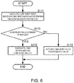
- Fig. 6 is a flowchart of a second load calculation.
- the arithmetic operation device may calculate the load index value as described above based on the load observation acceleration and the load observation posture (Sill).
- the arithmetic operation device may calculate the load by integrating the load index values (S112).
- the arithmetic operation device may calculate the load index value as described above based on the load observation acceleration and the load observation posture (Sill). If the load index value exceeds the threshold for the index value (SI13: YES), the arithmetic operation device may calculate the load by integrating the load index values (S112). If the load index value does not exceed the threshold for the index value (S113: NO), the arithmetic operation device may calculate the load without adding this load index value to the current integrated value (S114). If using the method illustrated in Fig. 6 , when the load index value is small and it does not have bad influences (exhaustion etc.) on the hull 100, this load index value may not be integrated. Therefore, the load can be calculated with higher precision.
- the movement state measuring part 20 may include antennas 201, 202, and 203, receivers 204, 205, and 206, an inertia sensor 207, and a processor 208.
- the antenna 201 may be connected to the receiver 204, the antenna 202 is connected to the receiver 205, and the antenna 203 is connected to the receiver 206.
- the receivers 204, 205, and 206 and the inertia sensor 207 may be connected to the processor 208.
- the antennas 201, 202, and 203 may be disposed so that all the antennas are not lined up linearly.
- the antenna 201 may receive a positioning signal and output it to the receiver 204.
- the antenna 202 may receive a positioning signal and output it to the receiver 205.
- the antenna 203 may receive a positioning signal and output it to the receiver 206.
- the positioning signal may be a signal transmitted from a positioning satellite, such as a GNSS satellite, and may be a signal obtained by modulating a carrier signal with a code peculiar to each positioning satellite.
- the carrier signal may be superimposed with a navigation message including, for example, orbital information of the positioning satellite.
- the antennas 201, 202, and 203 may receive at least four common positioning signals.
- the receiver 204 may acquire and track the positioning signal received by the antenna 201, and observe a code phase and a carrier phase.
- the receiver 205 may acquire and track the positioning signal received by the antenna 202, and observe a code phase and a carrier phase.
- the receiver 206 may acquire and track the positioning signal received by the antenna 203, and observe a code phase and a carrier phase.
- the receivers 204, 205, and 206 may observe the code phases and the carrier phases at a given time interval.
- the receivers 204, 205, and 206 may output the observed carrier phases to the processor 208 along with observation timings. Note that the receivers 204, 205, and 206 may output to the processor 208 the code phases, or may output to the processor 208 a code pseudo range acquired from the code phase or a positioning result by the code pseudo range.
- the inertia sensor 207 may include at least an acceleration sensor.
- the inertia sensor 207 may measure accelerations in three perpendicular axes of a hull coordinate system at an installed position, and output them to the processor 208.
- the processor 208 may calculate an angular velocity and the posture at the installed position of the movement state measuring part 20 in the hull 100 based on the carrier phases.
- the processor 208 may set base-line vectors of the antennas 201, 202, and 203 based on differences of the carrier phases (carrier phase difference) of the receivers 204, 205, and 206.
- the processor 208 may calculate the angular velocities on the three perpendicular axes of an absolute coordinate system based on changes in the base-line vectors acquired at every observation timing.
- the processor 208 may convert the angular velocities on the three perpendicular axes of the absolute coordinate system into the hull coordinate system to calculate the posture of the hull 100.
- the processor 208 may use the outputs of the inertia sensor 207 as they are to output them as the accelerations of the hull 100. Note that the processor 208 may correct the outputs of the inertia sensor 207 by using on the accelerations calculated based on the carrier phases to calculate the accelerations of the hull 100. Therefore, the calculation accuracy of the accelerations may improve.
- the acceleration measuring part 21 of Fig. 1 may be implemented by the inertia sensor 207 and the processor 208.
- the posture measuring part 22 illustrated in Fig. 1 may be implemented by the receivers 204, 205, and 206 and the processor 208. Therefore, the acceleration which can be used as the source of extraction of the load observation acceleration, and the posture which can be used as the source of extraction of the load observation posture can be measured by the simple configuration in which the positioning operation function and the inertia sensor are integrated into one device.
- the inertia sensor 207 can be omitted, and, in this case, the accelerations may be calculated based on the carrier phases.
- the antennas 201, 202, and 203, and the receivers 204, 205, and 206 may be omitted, and the inertia sensor 207 may be provided with the posture sensor(s), as well as the acceleration sensor(s).
- the inertia sensor 207 may be provided with an angular velocity sensor, and the posture which can be used as the source of extraction of the load observation posture may be calculated based on the output of the angular velocity sensor and the angular velocity by the carrier phase.
- slamming may be an impact produced when a wave collides with the hull 100.
- whipping may be vibration produced in the hull 100 by slamming.
- the extracting module 30 may observe slamming based on the acceleration at a plurality of observation timings.
- the extracting module 30 may observe whipping based on the acceleration or the change in the posture (angular velocity) at a plurality of observation timings. Then, the extracting module 30 may detect occurred timings of slamming and whipping. That is, the extracting module 30 may also function as a detector which detects the occurred timing of the phenomenon leading to the load on the hull.
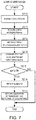
- Fig. 7 is a flowchart of a flow for observing slamming.
- the extracting module 30 may buffer the accelerations at the plurality of observation timings (S211). Note that, in this case, the extracting module 30 may also buffer the posture, in addition to the acceleration.
- the extracting module 30 may acquire a Z-axis acceleration "az" included in the acceleration at each observation timing (S212).
- the Z-axis acceleration az may be an acceleration in the vertical direction in the hull coordinate system.
- the extracting module 30 may highpass-filter (HPF) the Z-axis acceleration az (S213).
- HPF highpass-filter
- the Z-axis acceleration az caused by slamming may become a higher frequency than the steady Z-axis acceleration caused by the normal wave. Therefore, a threshold frequency of the highpass filtering may be set between the steady Z-axis acceleration caused by the normal wave and the Z-axis acceleration az caused by slamming which is acquired beforehand experimentally, experientially, or by a simulation. By performing this processing, the steady component caused by the normal wave included in the Z-axis acceleration may be removed.
- the extracting module 30 may compare a post-HPF acceleration azf with a threshold Th (S214).
- the threshold Th may be set as a lower limit of the Z-axis acceleration which can be determined that a wave collides with the hull 100 and slamming occurs.
- the threshold Th may be a value determined experimentally, experientially, or by the simulation, and may be changed based on the movement state of the hull. For example, the threshold Th may be raised in stormy weather and lowered during the ship is stopped.
- the extracting module 30 may detect that slamming occurred (S216). When the occurrence of slamming is detected, the extracting module 30 may save the accelerations at a plurality of observation timings before the detection of the slamming occurrence (S217). Here, the extracting module 30 may also save the posture, in addition to the acceleration. Note that, when only detecting slamming, Step S217 can be omitted.
- the extracting module 30 may set the post-HPF acceleration azf at an occurred timing of slamming as the load observation acceleration. Moreover, the extracting module 30 may set the posture at this occurred timing of slamming the load observation posture.
- the data processor 50 may determine that slamming is not occurred.
- the extracting module 30 can observe slamming.
- the extracting module 30 can observe slamming with high precision, and can extract the highly-precise load observation acceleration.
- the extracting module 30 can accurately separate the acceleration caused by the normal shake of the hull 100 and the acceleration caused by the impact of slamming, by using the post-HPF acceleration azf. Therefore, the extracting module 30 can observe slamming with higher precision.
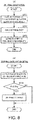
- Fig. 8(A) is an outline flowchart of an estimation of whipping.
- Fig. 8(B) is a detailed flowchart of the estimation of whipping.
- the extracting module 30 may acquire the postures at a plurality of observation timings before and after slamming is occurred (S301).
- the extracting module 30 may calculate a rate of change in the posture based on the postures at the plurality of observation timings.
- the extracting module 30 may conduct a frequency analysis of the rate of change in the posture (S302).
- the frequency analysis may be a processing which calculates a frequency spectrum of the rate of change in the posture (for example, FFT processing).
- the extracting module 30 may estimate a frequency of whipping and an intensity of whipping based on the frequency spectrum (S303).
- the extracting module 30 may detect a peak of the frequency spectrum of the rate of change in the posture, and detect a peak intensity PS (S311).
- the extracting module 30 may compare the peak intensity PS with a whipping detection threshold Thp.
- the whipping detection threshold Thp may be set as a lower limit of the spectral intensity which can be determined that whipping is occurred.
- the whipping detection threshold Thp may be a value determined experimentally, experientially, or by the simulation, and may be changed based on the movement state of the hull. For example, the whipping detection threshold Thp may be raised in stormy weather, or may be lowered during the ship is stopped.
- the extracting module 30 may determine that whipping is occurred (S313). Then, the extracting module 30 may set this peak intensity PS as the intensity of whipping. Moreover, the extracting module 30 may set the frequency at the peak intensity PS as the frequency of whipping. On the other hand, if the peak intensity PS is below the whipping detection threshold Thp (PS ⁇ Thp) (S312: NO), the extracting module 30 may determine that whipping is not occurred.
- the extracting module 30 may set the posture at the occurred timing of whipping as the load observation posture. Moreover, the extracting module 30 may set the post-HPF acceleration azf at this occurred timing of whipping as the load observation acceleration.
- the posture may be calculated with high precision based on the carrier phase. Therefore, by such a configuration and processing, the extracting module 30 can perform the determination of the occurrence of whipping certainly and accurately with the simple configuration. Moreover, the extracting module 30 can detect the intensity of whipping and the frequency of whipping certainly and accurately with the simple configuration. Therefore, the load index value and the load can be calculated accurately.
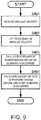
- Fig. 9 is a flowchart for calculating a change in the hull posture caused by slamming based on the angular velocity.
- the extracting module 30 may detect the occurrence of slamming as described above, and acquire the angular velocities at the plurality of observation timings before and after slamming is occurred (S401).
- the extracting module 30 may carry out a low pass filtering of the angular velocity (S402).
- the angular velocity may include various kinds of noises, and, normally, the frequency of noise may be higher than the frequency of the angular velocity resulting from slamming. Therefore, the noise may be removed by carrying out the low pass filtering of the angular velocity.
- the extracting module 30 may calculate the posture within a given period of time before and after slamming is occurred based on the angular velocity (S403). Note that such a given period of time may be set suitably, and may differ before and after slamming is occurred.
- the extracting module 30 may calculate an amount of posture change based on a difference between the postures before and after slamming is occurred (S404). Alternatively, the extracting module 30 may calculate a rate of posture change based on an amount of time change of the postures before and after slamming is occurred (S404).
- the load may be calculated based on the acceleration or the amount of change in the posture.
- a direction of displacement at a specific part of the hull 100 which can serve as one element of the load can be extracted.
- a direction of displacement in the Z-axis direction at the specific position of the hull 100, such as the bow 101 can be extracted.
- a hummering-in state of sea water i.e., the specific part of the bow 101 fell or the specific part of the bow 101 is pushed up by slamming, can be detected.
- the movement state measuring part 20 may be provided with the three antennas 201, 202, and 203 and the three receivers 204, 205, and 206.
- the acceleration sensor is provided as the inertia sensor
- the movement state measuring part 20 may be provided with at least two antennas and two receivers.
- Fig. 10 is a block diagram of the hull load observation device according to the second embodiment of the present disclosure.
- Fig. 11(A) is a plan view of a ship provided with the hull load observation device according to the second embodiment of the present disclosure.
- Fig. 11(B) is a side view of the ship provided with the hull load observation device according to the second embodiment of the present disclosure.
- a hull load observation device 10A may differ from the hull load observation device 10 according to the first embodiment in that it includes movement state measuring parts 20A, 20B, 20C, and 20D, and these parts are connected to a data processor 50A.
- the movement state measuring parts 20A, 20B, 20C, and 20D may be disposed at different positions of the hull 100.
- the movement state measuring parts 20A, 20B, 20C, and 20D may have the same configuration. As illustrated in Figs. 11(A) and 11(B) , the movement state measuring parts 20A, 20B, 20C, and 20D may be installed in the hull 100.
- the movement state measuring part 20A may be installed at the bow 101 of the hull 100.
- the movement state measuring part 20B may be installed at an intermediate position of the hull 100 in the bow-stern direction (X-axis direction of the hull coordinate system).
- the movement state measuring parts 20C and 20D may be installed on the top of the control room 110 near a stern 102 of the hull 100.
- the movement state measuring parts 20C and 20D may respectively be installed at one of a position near the starboard edge or the port side edge of the hull 100.
- the movement state measuring parts 20C and 20D may be disposed so that a base line connecting the movement state measuring parts 20C and 20D becomes parallel to the starboard-to-port-side direction (Y-axis direction of the hull coordinate system).
- the data processor 50A may perform the observation of the load similar to the observation of the load described in the first embodiment (the detections of slamming, the occurrence of whipping, etc.) for each installed position of the movement state measuring parts 20A, 20B, 20C, and 20D. Therefore, the hull load observation device 10 can observe the load at each of the plurality of positions of the hull 100.
- the plurality of loads at these positions can be synchronized with high precision by the time of the positioning system which can be demodulated from the positioning signal. Therefore, the load occurring at the same time at the plurality of positions of the hull 100 can be observed.
- the arrangement of the movement state measuring parts 20A, 20B, 20C, and 20D is not limited to this arrangement, but is desirable to be an arrangement so that all the movement state measuring parts 20A, 20B, 20C, and 20D are not lined up on a straight line. Therefore, even if the number of antennas provided to each of the movement state measuring parts 20A, 20B, 20C, and 20D is one, a plurality of base-line vectors can be set, and the base-line vectors can be used for the observation of the load.
- the plurality of base-line vectors can be set, and the base-line vectors can be used for the observation of the load based on the carrier phase.
- the movement state measuring part 20B may be disposed at a position which is not located on any of the base line connecting the movement state measuring part 20A and the movement state measuring part 20C, the base line connecting the movement state measuring part 20A and the movement state measuring part 20D, and the base line connecting the movement state measuring part 20C and the movement state measuring part 20D. Therefore, the number of base-line vectors which are not parallel to each other can be increases as much as possible within a limit of the number of movement state measuring parts.
- the movement state measuring parts 20A, 20B, 20C, and 20D may be desirable to be arranged in a wide range, i.e., so that the length of base-line vector connecting the respective movement state measuring parts becomes longer. Therefore, the calculation accuracy of the base-line vector may improve, and the calculation accuracy of the posture, and, as a result, the calculation accuracy of the load may improve.
- the data processor 50A can observe the following factors of the load.
- the factors of the load to be observed may include, for example, an estimation of an arrival direction of a wave colliding, and an estimation of the propagation characteristic of whipping.
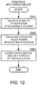
- Fig. 12 is a flowchart for estimating the arrival direction of the wave which causes slamming.
- the data processor 50A may acquire accelerations at a plurality of observation timings after slamming is occurred, outputted from the movement state measuring parts 20A, 20B, 20C, and 20D (S501).
- the data processor 50A may extract the load observation acceleration for every acceleration.
- the data processor 50A may synchronize the accelerations (the load observation accelerations) of the movement state measuring parts 20A, 20B, 20C, and 20D.
- the synchronization of the accelerations (the load observation accelerations) may be performed at an observation timing acquired with the accelerations (the load observation accelerations). Since the time of the positioning system is used as the observation timing, the synchronization of the observation timing may be performed with high precision.
- the data processor 50A may detect the maximum acceleration of the accelerations (the load observation accelerations) of the movement state measuring parts 20A, 20B, 20C, and 20D at the same timing (S502).
- the data processor 50A may estimate the position of the movement state measuring part which observed the maximum acceleration in the hull 100 as the arrival direction of the wave which causes slamming (S503).
- the hull load observation device 10A can certainly and accurately detect the arrival direction of the wave which causes slamming, and, as a result, it can observe the load accurately, with the simple configuration.
- the accelerations can be synchronized based on the highly-precise observation timing, the arrival direction of the wave which causes slamming can be detected without a large-scale construction but with the less-expensive configuration.
- Fig. 13 is a flowchart for estimating the whipping propagation characteristic.
- the data processor 50A may use the above-described method to detect whipping for each of the movement state measuring parts 20A, 20B, and 20C and 20D (S601).
- the data processor 50A may also detect whipping detection data including an intensity (amplitude) and a frequency of whipping.
- the data processor 50A may set a detection timing of the intensity (amplitude) and the frequency of whipping based on the observation timing, and have them included in the whipping detection data.
- the data processor 50A may synchronize the whipping detection data of the movement state measuring parts 20A, 20B, 20C, and 20D, and estimate the whipping propagation characteristic. That is, the data processor 50A may estimate the whipping propagation characteristic based on amplitude characteristics or frequency characteristics of the accelerations of the movement state measuring parts 20A, 20B, 20C, and 20D, or an amplitude characteristic or a frequency characteristic of the amount of change in the posture (the rate of change). In detail, the data processor 50A may estimate the propagation direction of whipping based on differences between the detection timings of the movement state measuring parts 20A, 20B, 20C, and 20D and the frequency components detected as whipping, i.e., a time series.
- the data processor 50A may estimate, for example, a damping characteristic of whipping by propagation based on the intensity of whipping detected by each of the movement state measuring parts 20A, 20B, 20C, and 20D. Therefore, the data processor 50A can estimate the intensity of whipping at a desired position of the hull 100. Therefore, the hull load observation device 10A can estimate and observe the load at an arbitrary position of the hull 100 by using the whipping propagation characteristic.
- the accelerations can be synchronized based on the highly-precise observation timing, the large-scale construction is not needed, and the whipping propagation characteristic can be estimated with the less-expensive configuration.
- Fig. 14 is a block diagram of the navigation support system to which the hull load observation device according to the embodiment of the present disclosure is applied.
- a navigation support system 80 may include the hull load observation device 10A, a support part 70, a ship speed acquiring part 61, a steering angle acquiring part 62, and an oceanic condition acquiring part 63.
- the hull load observation device 10A, the ship speed acquiring part 61, the steering angle acquiring part 62, and the oceanic condition acquiring part 63 may be connected to the support part 70.
- the ship speed acquiring part 61 may acquire a ship speed by calculating a speed based on the acceleration of any of the movement state measuring parts 20A, 20B, 20C, and 20D.
- a Doppler sonar attached to the hull 100 may be connected to the ship speed acquiring part 61, and the ship speed may be acquired based on an output value of the Doppler sonar by a known method.
- the steering angle acquiring part 62 may be connected to a steering angle sensor attached to the hull 100, and may acquire a steering angle based on an output value of the steering angle sensor by a known method.
- the oceanic condition acquiring part 63 may be connected to a wave radar attached to the hull 100, and may acquire an oceanic condition based on an output value of the wave radar by a known method. Moreover, the oceanic condition acquiring part 63 may have a wireless communication function, and acquire the oceanic condition from an exterior apparatus.
- the support part 70 may generate navigation support information for avoiding a generation of the load based on the information on the load obtained from the hull load observation device 10A, the ship speed obtained from the ship speed acquiring part 61, the steering angle obtained from the steering angle acquiring part 62, and the oceanic condition obtained from the oceanic condition acquiring part 63.
- the navigation support information may be information including a ship speed control and a steering angle control for avoiding slamming which may cause the load.
- the navigation support which reduces the load can be performed by using such a configuration and processing.
- the hull load observation device 10A may also be used.
- the hull load observation device described above mainly detects slamming or whipping as the phenomenon leading to the load, it is also possible to detect sagging and hogging of the hull by using the configuration of the hull load observation device 10A.
Landscapes
- Engineering & Computer Science (AREA)
- Chemical & Material Sciences (AREA)
- Combustion & Propulsion (AREA)
- Mechanical Engineering (AREA)
- Ocean & Marine Engineering (AREA)
- Health & Medical Sciences (AREA)
- Public Health (AREA)
- Radar, Positioning & Navigation (AREA)
- Remote Sensing (AREA)
- Position Fixing By Use Of Radio Waves (AREA)
Applications Claiming Priority (2)
| Application Number | Priority Date | Filing Date | Title |
|---|---|---|---|
| JP2017039964 | 2017-03-03 | ||
| PCT/JP2018/006432 WO2018159440A1 (ja) | 2017-03-03 | 2018-02-22 | 船体負荷観測装置、船体負荷観測方法、および、船体負荷観測プログラム |
Publications (3)
| Publication Number | Publication Date |
|---|---|
| EP3590818A1 true EP3590818A1 (de) | 2020-01-08 |
| EP3590818A4 EP3590818A4 (de) | 2021-01-20 |
| EP3590818B1 EP3590818B1 (de) | 2023-08-30 |
Family
ID=63371158
Family Applications (1)
| Application Number | Title | Priority Date | Filing Date |
|---|---|---|---|
| EP18761760.0A Active EP3590818B1 (de) | 2017-03-03 | 2018-02-22 | Schiffsladungsüberwachungsvorrichtung, schiffsladungsüberwachungsverfahren und schiffsladungsüberwachungsprogramm |
Country Status (4)
| Country | Link |
|---|---|
| EP (1) | EP3590818B1 (de) |
| JP (1) | JP6880171B2 (de) |
| CN (1) | CN110366522B (de) |
| WO (1) | WO2018159440A1 (de) |
Families Citing this family (1)
| Publication number | Priority date | Publication date | Assignee | Title |
|---|---|---|---|---|
| JP2024143859A (ja) * | 2023-03-30 | 2024-10-11 | 横河電機株式会社 | 装置、方法およびプログラム |
Family Cites Families (6)
| Publication number | Priority date | Publication date | Assignee | Title |
|---|---|---|---|---|
| US6263297B1 (en) * | 1999-03-11 | 2001-07-17 | The United States Of America As Represented By The Secretary Of The Navy | Programmed computation of predicted loading of ship hull |
| US6996493B1 (en) * | 2004-02-11 | 2006-02-07 | The United States Of America As Represented By The Secretary Of The Navy | Programmed computation of predicted pressure loads on marine vessels |
| WO2008152613A2 (en) * | 2007-06-14 | 2008-12-18 | Fincantieri Cantieri Navali Italiani S.P.A. | Device and method for operator guidance of a ship |
| JP5479788B2 (ja) * | 2009-06-23 | 2014-04-23 | 古野電気株式会社 | 自動操舵システム及び自動操舵装置 |
| JP2012051500A (ja) * | 2010-09-02 | 2012-03-15 | Universal Shipbuilding Corp | 荒天時警報発令システム |
| EP3241038B1 (de) * | 2014-12-30 | 2019-05-29 | Centro per gli Studi di Tecnica Navale CETENA S.p.A. | Strukturüberwachungssystem des rumpfes eines schiffes mit integriertem navigationsentscheidungsunterstützungssystem |
-
2018
- 2018-02-22 JP JP2019502928A patent/JP6880171B2/ja active Active
- 2018-02-22 EP EP18761760.0A patent/EP3590818B1/de active Active
- 2018-02-22 CN CN201880014702.1A patent/CN110366522B/zh active Active
- 2018-02-22 WO PCT/JP2018/006432 patent/WO2018159440A1/ja not_active Ceased
Also Published As
| Publication number | Publication date |
|---|---|
| JPWO2018159440A1 (ja) | 2019-12-26 |
| EP3590818A4 (de) | 2021-01-20 |
| CN110366522B (zh) | 2022-02-11 |
| WO2018159440A1 (ja) | 2018-09-07 |
| JP6880171B2 (ja) | 2021-06-02 |
| EP3590818B1 (de) | 2023-08-30 |
| CN110366522A (zh) | 2019-10-22 |
Similar Documents
| Publication | Publication Date | Title |
|---|---|---|
| EP3028070B1 (de) | Navigation und integritätsüberwachung | |
| EP2169422B1 (de) | System und Verfahren zur akustischen Verfolgung der Bahn eines Unterwasserfahrzeugs | |
| Matos et al. | Development and implementation of a low-cost LBL navigation system for an AUV | |
| EP3109674B1 (de) | Vorrichtung zur erkennung von strukturverlagerungen, system zum teilen von strukturverlagerungen, verfahren zur erkennung von strukturverlagerungen und programm zur erkennung von strukturverlagerungen | |
| KR101257097B1 (ko) | 선 배열 소나 및 이의 표적방위 검출방법 | |
| CN113311388B (zh) | 一种水下机器人的超短基线定位系统 | |
| KR101196510B1 (ko) | 표적 데이터의 수동적 결정 방법 및 장치 | |
| JP2009229424A (ja) | 津波監視装置 | |
| CN109029465A (zh) | 一种无人艇基于毫米波雷达的跟踪和避障系统 | |
| KR20170078835A (ko) | 적어도 하나의 선박의 수면속도를 계산하는 방법 및 상기 선박의 경로상의 모든 지점에서 각각의 표류벡터를 추론하는 방법 | |
| EP3590818B1 (de) | Schiffsladungsüberwachungsvorrichtung, schiffsladungsüberwachungsverfahren und schiffsladungsüberwachungsprogramm | |
| RU2620925C1 (ru) | Способ определения направления и дальности до источника сигналов | |
| WO2017141614A1 (ja) | 津波観測装置、津波観測システム、津波観測方法 | |
| EP1970723A1 (de) | Verfahren zur Berechnung verbesserter SBAS-Schutzebenen, die für nicht gesteuerte Umgebungen gelten | |
| JP2011185719A (ja) | 追尾レーダ装置 | |
| RU2405166C2 (ru) | Способ определения местоположения передатчика переносным пеленгатором | |
| CN117169923A (zh) | 移动场景下的gnss欺骗干扰检测方法 | |
| KR101837845B1 (ko) | 수중 표적 정보 획득 시스템 및 방법 | |
| KR101513100B1 (ko) | 단일안테나 위성항법 수신기와 관성센서를 이용하는 항법위성신호 기만탐지 장치 및 방법 | |
| AU2012244785B2 (en) | Method and device for determining target parameters | |
| Cao et al. | Travel time processing for LBL positioning system | |
| RU2625094C1 (ru) | Способ определения пеленга и дальности до источника сигналов | |
| KR100760979B1 (ko) | 선박의 위치감지 시스템 및 그 방법 | |
| RU108133U1 (ru) | Измеритель деформаций корпуса корабля | |
| JP4948485B2 (ja) | 方位探知装置 |
Legal Events
| Date | Code | Title | Description |
|---|---|---|---|
| STAA | Information on the status of an ep patent application or granted ep patent |
Free format text: STATUS: THE INTERNATIONAL PUBLICATION HAS BEEN MADE |
|
| PUAI | Public reference made under article 153(3) epc to a published international application that has entered the european phase |
Free format text: ORIGINAL CODE: 0009012 |
|
| STAA | Information on the status of an ep patent application or granted ep patent |
Free format text: STATUS: REQUEST FOR EXAMINATION WAS MADE |
|
| 17P | Request for examination filed |
Effective date: 20190924 |
|
| AK | Designated contracting states |
Kind code of ref document: A1 Designated state(s): AL AT BE BG CH CY CZ DE DK EE ES FI FR GB GR HR HU IE IS IT LI LT LU LV MC MK MT NL NO PL PT RO RS SE SI SK SM TR |
|
| AX | Request for extension of the european patent |
Extension state: BA ME |
|
| DAV | Request for validation of the european patent (deleted) | ||
| DAX | Request for extension of the european patent (deleted) | ||
| A4 | Supplementary search report drawn up and despatched |
Effective date: 20201217 |
|
| RIC1 | Information provided on ipc code assigned before grant |
Ipc: B63B 43/20 20060101ALI20201211BHEP Ipc: B63B 43/00 20060101AFI20201211BHEP Ipc: B63B 79/00 20200101ALI20201211BHEP Ipc: B63B 49/00 20060101ALI20201211BHEP |
|
| GRAP | Despatch of communication of intention to grant a patent |
Free format text: ORIGINAL CODE: EPIDOSNIGR1 |
|
| STAA | Information on the status of an ep patent application or granted ep patent |
Free format text: STATUS: GRANT OF PATENT IS INTENDED |
|
| INTG | Intention to grant announced |
Effective date: 20230526 |
|
| GRAS | Grant fee paid |
Free format text: ORIGINAL CODE: EPIDOSNIGR3 |
|
| GRAA | (expected) grant |
Free format text: ORIGINAL CODE: 0009210 |
|
| STAA | Information on the status of an ep patent application or granted ep patent |
Free format text: STATUS: THE PATENT HAS BEEN GRANTED |
|
| AK | Designated contracting states |
Kind code of ref document: B1 Designated state(s): AL AT BE BG CH CY CZ DE DK EE ES FI FR GB GR HR HU IE IS IT LI LT LU LV MC MK MT NL NO PL PT RO RS SE SI SK SM TR |
|
| REG | Reference to a national code |
Ref country code: GB Ref legal event code: FG4D |
|
| REG | Reference to a national code |
Ref country code: CH Ref legal event code: EP |
|
| REG | Reference to a national code |
Ref country code: DE Ref legal event code: R096 Ref document number: 602018056476 Country of ref document: DE |
|
| REG | Reference to a national code |
Ref country code: IE Ref legal event code: FG4D |
|
| REG | Reference to a national code |
Ref country code: LT Ref legal event code: MG9D |
|
| REG | Reference to a national code |
Ref country code: NL Ref legal event code: MP Effective date: 20230830 |
|
| REG | Reference to a national code |
Ref country code: AT Ref legal event code: MK05 Ref document number: 1605124 Country of ref document: AT Kind code of ref document: T Effective date: 20230830 |
|
| PG25 | Lapsed in a contracting state [announced via postgrant information from national office to epo] |
Ref country code: GR Free format text: LAPSE BECAUSE OF FAILURE TO SUBMIT A TRANSLATION OF THE DESCRIPTION OR TO PAY THE FEE WITHIN THE PRESCRIBED TIME-LIMIT Effective date: 20231201 |
|
| PG25 | Lapsed in a contracting state [announced via postgrant information from national office to epo] |
Ref country code: IS Free format text: LAPSE BECAUSE OF FAILURE TO SUBMIT A TRANSLATION OF THE DESCRIPTION OR TO PAY THE FEE WITHIN THE PRESCRIBED TIME-LIMIT Effective date: 20231230 |
|
| PG25 | Lapsed in a contracting state [announced via postgrant information from national office to epo] |
Ref country code: SE Free format text: LAPSE BECAUSE OF FAILURE TO SUBMIT A TRANSLATION OF THE DESCRIPTION OR TO PAY THE FEE WITHIN THE PRESCRIBED TIME-LIMIT Effective date: 20230830 Ref country code: RS Free format text: LAPSE BECAUSE OF FAILURE TO SUBMIT A TRANSLATION OF THE DESCRIPTION OR TO PAY THE FEE WITHIN THE PRESCRIBED TIME-LIMIT Effective date: 20230830 Ref country code: NO Free format text: LAPSE BECAUSE OF FAILURE TO SUBMIT A TRANSLATION OF THE DESCRIPTION OR TO PAY THE FEE WITHIN THE PRESCRIBED TIME-LIMIT Effective date: 20231130 Ref country code: LV Free format text: LAPSE BECAUSE OF FAILURE TO SUBMIT A TRANSLATION OF THE DESCRIPTION OR TO PAY THE FEE WITHIN THE PRESCRIBED TIME-LIMIT Effective date: 20230830 Ref country code: LT Free format text: LAPSE BECAUSE OF FAILURE TO SUBMIT A TRANSLATION OF THE DESCRIPTION OR TO PAY THE FEE WITHIN THE PRESCRIBED TIME-LIMIT Effective date: 20230830 Ref country code: IS Free format text: LAPSE BECAUSE OF FAILURE TO SUBMIT A TRANSLATION OF THE DESCRIPTION OR TO PAY THE FEE WITHIN THE PRESCRIBED TIME-LIMIT Effective date: 20231230 Ref country code: HR Free format text: LAPSE BECAUSE OF FAILURE TO SUBMIT A TRANSLATION OF THE DESCRIPTION OR TO PAY THE FEE WITHIN THE PRESCRIBED TIME-LIMIT Effective date: 20230830 Ref country code: GR Free format text: LAPSE BECAUSE OF FAILURE TO SUBMIT A TRANSLATION OF THE DESCRIPTION OR TO PAY THE FEE WITHIN THE PRESCRIBED TIME-LIMIT Effective date: 20231201 Ref country code: FI Free format text: LAPSE BECAUSE OF FAILURE TO SUBMIT A TRANSLATION OF THE DESCRIPTION OR TO PAY THE FEE WITHIN THE PRESCRIBED TIME-LIMIT Effective date: 20230830 Ref country code: AT Free format text: LAPSE BECAUSE OF FAILURE TO SUBMIT A TRANSLATION OF THE DESCRIPTION OR TO PAY THE FEE WITHIN THE PRESCRIBED TIME-LIMIT Effective date: 20230830 |
|
| PG25 | Lapsed in a contracting state [announced via postgrant information from national office to epo] |
Ref country code: PL Free format text: LAPSE BECAUSE OF FAILURE TO SUBMIT A TRANSLATION OF THE DESCRIPTION OR TO PAY THE FEE WITHIN THE PRESCRIBED TIME-LIMIT Effective date: 20230830 Ref country code: NL Free format text: LAPSE BECAUSE OF FAILURE TO SUBMIT A TRANSLATION OF THE DESCRIPTION OR TO PAY THE FEE WITHIN THE PRESCRIBED TIME-LIMIT Effective date: 20230830 |
|
| PG25 | Lapsed in a contracting state [announced via postgrant information from national office to epo] |
Ref country code: ES Free format text: LAPSE BECAUSE OF FAILURE TO SUBMIT A TRANSLATION OF THE DESCRIPTION OR TO PAY THE FEE WITHIN THE PRESCRIBED TIME-LIMIT Effective date: 20230830 |
|
| PG25 | Lapsed in a contracting state [announced via postgrant information from national office to epo] |
Ref country code: SM Free format text: LAPSE BECAUSE OF FAILURE TO SUBMIT A TRANSLATION OF THE DESCRIPTION OR TO PAY THE FEE WITHIN THE PRESCRIBED TIME-LIMIT Effective date: 20230830 Ref country code: RO Free format text: LAPSE BECAUSE OF FAILURE TO SUBMIT A TRANSLATION OF THE DESCRIPTION OR TO PAY THE FEE WITHIN THE PRESCRIBED TIME-LIMIT Effective date: 20230830 Ref country code: ES Free format text: LAPSE BECAUSE OF FAILURE TO SUBMIT A TRANSLATION OF THE DESCRIPTION OR TO PAY THE FEE WITHIN THE PRESCRIBED TIME-LIMIT Effective date: 20230830 Ref country code: EE Free format text: LAPSE BECAUSE OF FAILURE TO SUBMIT A TRANSLATION OF THE DESCRIPTION OR TO PAY THE FEE WITHIN THE PRESCRIBED TIME-LIMIT Effective date: 20230830 Ref country code: DK Free format text: LAPSE BECAUSE OF FAILURE TO SUBMIT A TRANSLATION OF THE DESCRIPTION OR TO PAY THE FEE WITHIN THE PRESCRIBED TIME-LIMIT Effective date: 20230830 Ref country code: CZ Free format text: LAPSE BECAUSE OF FAILURE TO SUBMIT A TRANSLATION OF THE DESCRIPTION OR TO PAY THE FEE WITHIN THE PRESCRIBED TIME-LIMIT Effective date: 20230830 Ref country code: PT Free format text: LAPSE BECAUSE OF FAILURE TO SUBMIT A TRANSLATION OF THE DESCRIPTION OR TO PAY THE FEE WITHIN THE PRESCRIBED TIME-LIMIT Effective date: 20240102 Ref country code: SK Free format text: LAPSE BECAUSE OF FAILURE TO SUBMIT A TRANSLATION OF THE DESCRIPTION OR TO PAY THE FEE WITHIN THE PRESCRIBED TIME-LIMIT Effective date: 20230830 |
|
| PG25 | Lapsed in a contracting state [announced via postgrant information from national office to epo] |
Ref country code: IT Free format text: LAPSE BECAUSE OF FAILURE TO SUBMIT A TRANSLATION OF THE DESCRIPTION OR TO PAY THE FEE WITHIN THE PRESCRIBED TIME-LIMIT Effective date: 20230830 |
|
| REG | Reference to a national code |
Ref country code: DE Ref legal event code: R097 Ref document number: 602018056476 Country of ref document: DE |
|
| PLBE | No opposition filed within time limit |
Free format text: ORIGINAL CODE: 0009261 |
|
| STAA | Information on the status of an ep patent application or granted ep patent |
Free format text: STATUS: NO OPPOSITION FILED WITHIN TIME LIMIT |
|
| PG25 | Lapsed in a contracting state [announced via postgrant information from national office to epo] |
Ref country code: SI Free format text: LAPSE BECAUSE OF FAILURE TO SUBMIT A TRANSLATION OF THE DESCRIPTION OR TO PAY THE FEE WITHIN THE PRESCRIBED TIME-LIMIT Effective date: 20230830 |
|
| 26N | No opposition filed |
Effective date: 20240603 |
|
| PG25 | Lapsed in a contracting state [announced via postgrant information from national office to epo] |
Ref country code: MC Free format text: LAPSE BECAUSE OF FAILURE TO SUBMIT A TRANSLATION OF THE DESCRIPTION OR TO PAY THE FEE WITHIN THE PRESCRIBED TIME-LIMIT Effective date: 20230830 |
|
| REG | Reference to a national code |
Ref country code: CH Ref legal event code: PL |
|
| PG25 | Lapsed in a contracting state [announced via postgrant information from national office to epo] |
Ref country code: LU Free format text: LAPSE BECAUSE OF NON-PAYMENT OF DUE FEES Effective date: 20240222 |
|
| PG25 | Lapsed in a contracting state [announced via postgrant information from national office to epo] |
Ref country code: CH Free format text: LAPSE BECAUSE OF NON-PAYMENT OF DUE FEES Effective date: 20240229 |
|
| PG25 | Lapsed in a contracting state [announced via postgrant information from national office to epo] |
Ref country code: LU Free format text: LAPSE BECAUSE OF NON-PAYMENT OF DUE FEES Effective date: 20240222 Ref country code: CH Free format text: LAPSE BECAUSE OF NON-PAYMENT OF DUE FEES Effective date: 20240229 |
|
| PG25 | Lapsed in a contracting state [announced via postgrant information from national office to epo] |
Ref country code: BG Free format text: LAPSE BECAUSE OF FAILURE TO SUBMIT A TRANSLATION OF THE DESCRIPTION OR TO PAY THE FEE WITHIN THE PRESCRIBED TIME-LIMIT Effective date: 20230830 |
|
| PG25 | Lapsed in a contracting state [announced via postgrant information from national office to epo] |
Ref country code: BG Free format text: LAPSE BECAUSE OF FAILURE TO SUBMIT A TRANSLATION OF THE DESCRIPTION OR TO PAY THE FEE WITHIN THE PRESCRIBED TIME-LIMIT Effective date: 20230830 |
|
| REG | Reference to a national code |
Ref country code: BE Ref legal event code: MM Effective date: 20240229 |
|
| PG25 | Lapsed in a contracting state [announced via postgrant information from national office to epo] |
Ref country code: BE Free format text: LAPSE BECAUSE OF NON-PAYMENT OF DUE FEES Effective date: 20240229 |
|
| PG25 | Lapsed in a contracting state [announced via postgrant information from national office to epo] |
Ref country code: FR Free format text: LAPSE BECAUSE OF NON-PAYMENT OF DUE FEES Effective date: 20240229 |
|
| PG25 | Lapsed in a contracting state [announced via postgrant information from national office to epo] |
Ref country code: IE Free format text: LAPSE BECAUSE OF NON-PAYMENT OF DUE FEES Effective date: 20240222 |
|
| PG25 | Lapsed in a contracting state [announced via postgrant information from national office to epo] |
Ref country code: IE Free format text: LAPSE BECAUSE OF NON-PAYMENT OF DUE FEES Effective date: 20240222 Ref country code: FR Free format text: LAPSE BECAUSE OF NON-PAYMENT OF DUE FEES Effective date: 20240229 Ref country code: BE Free format text: LAPSE BECAUSE OF NON-PAYMENT OF DUE FEES Effective date: 20240229 |
|
| PG25 | Lapsed in a contracting state [announced via postgrant information from national office to epo] |
Ref country code: CY Free format text: LAPSE BECAUSE OF FAILURE TO SUBMIT A TRANSLATION OF THE DESCRIPTION OR TO PAY THE FEE WITHIN THE PRESCRIBED TIME-LIMIT; INVALID AB INITIO Effective date: 20180222 |
|
| PG25 | Lapsed in a contracting state [announced via postgrant information from national office to epo] |
Ref country code: HU Free format text: LAPSE BECAUSE OF FAILURE TO SUBMIT A TRANSLATION OF THE DESCRIPTION OR TO PAY THE FEE WITHIN THE PRESCRIBED TIME-LIMIT; INVALID AB INITIO Effective date: 20180222 |
|
| PG25 | Lapsed in a contracting state [announced via postgrant information from national office to epo] |
Ref country code: TR Free format text: LAPSE BECAUSE OF FAILURE TO SUBMIT A TRANSLATION OF THE DESCRIPTION OR TO PAY THE FEE WITHIN THE PRESCRIBED TIME-LIMIT Effective date: 20230830 |
|
| PGFP | Annual fee paid to national office [announced via postgrant information from national office to epo] |
Ref country code: GB Payment date: 20260106 Year of fee payment: 9 |
|
| PGFP | Annual fee paid to national office [announced via postgrant information from national office to epo] |
Ref country code: DE Payment date: 20251230 Year of fee payment: 9 |