EP3590778B1 - Ventilanordnung - Google Patents
Ventilanordnung Download PDFInfo
- Publication number
- EP3590778B1 EP3590778B1 EP19183718.6A EP19183718A EP3590778B1 EP 3590778 B1 EP3590778 B1 EP 3590778B1 EP 19183718 A EP19183718 A EP 19183718A EP 3590778 B1 EP3590778 B1 EP 3590778B1
- Authority
- EP
- European Patent Office
- Prior art keywords
- distributor
- fact
- chamber
- valve assembly
- port
- Prior art date
- Legal status (The legal status is an assumption and is not a legal conclusion. Google has not performed a legal analysis and makes no representation as to the accuracy of the status listed.)
- Active
Links
Images
Classifications
-
- B—PERFORMING OPERATIONS; TRANSPORTING
- B60—VEHICLES IN GENERAL
- B60T—VEHICLE BRAKE CONTROL SYSTEMS OR PARTS THEREOF; BRAKE CONTROL SYSTEMS OR PARTS THEREOF, IN GENERAL; ARRANGEMENT OF BRAKING ELEMENTS ON VEHICLES IN GENERAL; PORTABLE DEVICES FOR PREVENTING UNWANTED MOVEMENT OF VEHICLES; VEHICLE MODIFICATIONS TO FACILITATE COOLING OF BRAKES
- B60T13/00—Transmitting braking action from initiating means to ultimate brake actuator with power assistance or drive; Brake systems incorporating such transmitting means, e.g. air-pressure brake systems
- B60T13/10—Transmitting braking action from initiating means to ultimate brake actuator with power assistance or drive; Brake systems incorporating such transmitting means, e.g. air-pressure brake systems with fluid assistance, drive, or release
- B60T13/24—Transmitting braking action from initiating means to ultimate brake actuator with power assistance or drive; Brake systems incorporating such transmitting means, e.g. air-pressure brake systems with fluid assistance, drive, or release the fluid being gaseous
- B60T13/241—Differential pressure systems
- B60T13/242—The control valve is provided as one unit with the servomotor cylinder
- B60T13/243—Mechanical command of the control valve, mechanical transmission to the brakes
-
- B—PERFORMING OPERATIONS; TRANSPORTING
- B60—VEHICLES IN GENERAL
- B60T—VEHICLE BRAKE CONTROL SYSTEMS OR PARTS THEREOF; BRAKE CONTROL SYSTEMS OR PARTS THEREOF, IN GENERAL; ARRANGEMENT OF BRAKING ELEMENTS ON VEHICLES IN GENERAL; PORTABLE DEVICES FOR PREVENTING UNWANTED MOVEMENT OF VEHICLES; VEHICLE MODIFICATIONS TO FACILITATE COOLING OF BRAKES
- B60T13/00—Transmitting braking action from initiating means to ultimate brake actuator with power assistance or drive; Brake systems incorporating such transmitting means, e.g. air-pressure brake systems
- B60T13/10—Transmitting braking action from initiating means to ultimate brake actuator with power assistance or drive; Brake systems incorporating such transmitting means, e.g. air-pressure brake systems with fluid assistance, drive, or release
- B60T13/24—Transmitting braking action from initiating means to ultimate brake actuator with power assistance or drive; Brake systems incorporating such transmitting means, e.g. air-pressure brake systems with fluid assistance, drive, or release the fluid being gaseous
- B60T13/241—Differential pressure systems
- B60T13/242—The control valve is provided as one unit with the servomotor cylinder
- B60T13/244—Mechanical command of the control valve, hydraulic transmission to the brakes
-
- B—PERFORMING OPERATIONS; TRANSPORTING
- B60—VEHICLES IN GENERAL
- B60T—VEHICLE BRAKE CONTROL SYSTEMS OR PARTS THEREOF; BRAKE CONTROL SYSTEMS OR PARTS THEREOF, IN GENERAL; ARRANGEMENT OF BRAKING ELEMENTS ON VEHICLES IN GENERAL; PORTABLE DEVICES FOR PREVENTING UNWANTED MOVEMENT OF VEHICLES; VEHICLE MODIFICATIONS TO FACILITATE COOLING OF BRAKES
- B60T13/00—Transmitting braking action from initiating means to ultimate brake actuator with power assistance or drive; Brake systems incorporating such transmitting means, e.g. air-pressure brake systems
- B60T13/10—Transmitting braking action from initiating means to ultimate brake actuator with power assistance or drive; Brake systems incorporating such transmitting means, e.g. air-pressure brake systems with fluid assistance, drive, or release
- B60T13/24—Transmitting braking action from initiating means to ultimate brake actuator with power assistance or drive; Brake systems incorporating such transmitting means, e.g. air-pressure brake systems with fluid assistance, drive, or release the fluid being gaseous
- B60T13/241—Differential pressure systems
- B60T13/246—The control valve is provided apart from the servomotor cylinder
- B60T13/248—Mechanical command of the control valve, hydraulic transmission to the brakes
-
- B—PERFORMING OPERATIONS; TRANSPORTING
- B60—VEHICLES IN GENERAL
- B60T—VEHICLE BRAKE CONTROL SYSTEMS OR PARTS THEREOF; BRAKE CONTROL SYSTEMS OR PARTS THEREOF, IN GENERAL; ARRANGEMENT OF BRAKING ELEMENTS ON VEHICLES IN GENERAL; PORTABLE DEVICES FOR PREVENTING UNWANTED MOVEMENT OF VEHICLES; VEHICLE MODIFICATIONS TO FACILITATE COOLING OF BRAKES
- B60T15/00—Construction arrangement, or operation of valves incorporated in power brake systems and not covered by groups B60T11/00 or B60T13/00
- B60T15/02—Application and release valves
- B60T15/18—Triple or other relay valves which allow step-wise application or release and which are actuated by brake-pipe pressure variation to connect brake cylinders or equivalent to compressed air or vacuum source or atmosphere
- B60T15/181—Trailer control valves
-
- B—PERFORMING OPERATIONS; TRANSPORTING
- B60—VEHICLES IN GENERAL
- B60T—VEHICLE BRAKE CONTROL SYSTEMS OR PARTS THEREOF; BRAKE CONTROL SYSTEMS OR PARTS THEREOF, IN GENERAL; ARRANGEMENT OF BRAKING ELEMENTS ON VEHICLES IN GENERAL; PORTABLE DEVICES FOR PREVENTING UNWANTED MOVEMENT OF VEHICLES; VEHICLE MODIFICATIONS TO FACILITATE COOLING OF BRAKES
- B60T15/00—Construction arrangement, or operation of valves incorporated in power brake systems and not covered by groups B60T11/00 or B60T13/00
- B60T15/02—Application and release valves
- B60T15/18—Triple or other relay valves which allow step-wise application or release and which are actuated by brake-pipe pressure variation to connect brake cylinders or equivalent to compressed air or vacuum source or atmosphere
- B60T15/182—Trailer brake valves
-
- B—PERFORMING OPERATIONS; TRANSPORTING
- B60—VEHICLES IN GENERAL
- B60T—VEHICLE BRAKE CONTROL SYSTEMS OR PARTS THEREOF; BRAKE CONTROL SYSTEMS OR PARTS THEREOF, IN GENERAL; ARRANGEMENT OF BRAKING ELEMENTS ON VEHICLES IN GENERAL; PORTABLE DEVICES FOR PREVENTING UNWANTED MOVEMENT OF VEHICLES; VEHICLE MODIFICATIONS TO FACILITATE COOLING OF BRAKES
- B60T15/00—Construction arrangement, or operation of valves incorporated in power brake systems and not covered by groups B60T11/00 or B60T13/00
- B60T15/02—Application and release valves
- B60T15/18—Triple or other relay valves which allow step-wise application or release and which are actuated by brake-pipe pressure variation to connect brake cylinders or equivalent to compressed air or vacuum source or atmosphere
- B60T15/20—Triple or other relay valves which allow step-wise application or release and which are actuated by brake-pipe pressure variation to connect brake cylinders or equivalent to compressed air or vacuum source or atmosphere controlled by two fluid pressures
- B60T15/203—Trailer control valves
-
- B—PERFORMING OPERATIONS; TRANSPORTING
- B60—VEHICLES IN GENERAL
- B60T—VEHICLE BRAKE CONTROL SYSTEMS OR PARTS THEREOF; BRAKE CONTROL SYSTEMS OR PARTS THEREOF, IN GENERAL; ARRANGEMENT OF BRAKING ELEMENTS ON VEHICLES IN GENERAL; PORTABLE DEVICES FOR PREVENTING UNWANTED MOVEMENT OF VEHICLES; VEHICLE MODIFICATIONS TO FACILITATE COOLING OF BRAKES
- B60T15/00—Construction arrangement, or operation of valves incorporated in power brake systems and not covered by groups B60T11/00 or B60T13/00
- B60T15/02—Application and release valves
- B60T15/18—Triple or other relay valves which allow step-wise application or release and which are actuated by brake-pipe pressure variation to connect brake cylinders or equivalent to compressed air or vacuum source or atmosphere
- B60T15/20—Triple or other relay valves which allow step-wise application or release and which are actuated by brake-pipe pressure variation to connect brake cylinders or equivalent to compressed air or vacuum source or atmosphere controlled by two fluid pressures
- B60T15/206—Trailer brake valves
-
- B—PERFORMING OPERATIONS; TRANSPORTING
- B60—VEHICLES IN GENERAL
- B60T—VEHICLE BRAKE CONTROL SYSTEMS OR PARTS THEREOF; BRAKE CONTROL SYSTEMS OR PARTS THEREOF, IN GENERAL; ARRANGEMENT OF BRAKING ELEMENTS ON VEHICLES IN GENERAL; PORTABLE DEVICES FOR PREVENTING UNWANTED MOVEMENT OF VEHICLES; VEHICLE MODIFICATIONS TO FACILITATE COOLING OF BRAKES
- B60T15/00—Construction arrangement, or operation of valves incorporated in power brake systems and not covered by groups B60T11/00 or B60T13/00
- B60T15/02—Application and release valves
- B60T15/18—Triple or other relay valves which allow step-wise application or release and which are actuated by brake-pipe pressure variation to connect brake cylinders or equivalent to compressed air or vacuum source or atmosphere
- B60T15/20—Triple or other relay valves which allow step-wise application or release and which are actuated by brake-pipe pressure variation to connect brake cylinders or equivalent to compressed air or vacuum source or atmosphere controlled by two fluid pressures
- B60T15/22—Triple or other relay valves which allow step-wise application or release and which are actuated by brake-pipe pressure variation to connect brake cylinders or equivalent to compressed air or vacuum source or atmosphere controlled by two fluid pressures with one or more auxiliary valves, for braking, releasing, filling reservoirs
- B60T15/223—Trailer control valves
-
- B—PERFORMING OPERATIONS; TRANSPORTING
- B60—VEHICLES IN GENERAL
- B60T—VEHICLE BRAKE CONTROL SYSTEMS OR PARTS THEREOF; BRAKE CONTROL SYSTEMS OR PARTS THEREOF, IN GENERAL; ARRANGEMENT OF BRAKING ELEMENTS ON VEHICLES IN GENERAL; PORTABLE DEVICES FOR PREVENTING UNWANTED MOVEMENT OF VEHICLES; VEHICLE MODIFICATIONS TO FACILITATE COOLING OF BRAKES
- B60T15/00—Construction arrangement, or operation of valves incorporated in power brake systems and not covered by groups B60T11/00 or B60T13/00
- B60T15/02—Application and release valves
- B60T15/18—Triple or other relay valves which allow step-wise application or release and which are actuated by brake-pipe pressure variation to connect brake cylinders or equivalent to compressed air or vacuum source or atmosphere
- B60T15/20—Triple or other relay valves which allow step-wise application or release and which are actuated by brake-pipe pressure variation to connect brake cylinders or equivalent to compressed air or vacuum source or atmosphere controlled by two fluid pressures
- B60T15/22—Triple or other relay valves which allow step-wise application or release and which are actuated by brake-pipe pressure variation to connect brake cylinders or equivalent to compressed air or vacuum source or atmosphere controlled by two fluid pressures with one or more auxiliary valves, for braking, releasing, filling reservoirs
- B60T15/226—Trailer brake valves
-
- B—PERFORMING OPERATIONS; TRANSPORTING
- B60—VEHICLES IN GENERAL
- B60T—VEHICLE BRAKE CONTROL SYSTEMS OR PARTS THEREOF; BRAKE CONTROL SYSTEMS OR PARTS THEREOF, IN GENERAL; ARRANGEMENT OF BRAKING ELEMENTS ON VEHICLES IN GENERAL; PORTABLE DEVICES FOR PREVENTING UNWANTED MOVEMENT OF VEHICLES; VEHICLE MODIFICATIONS TO FACILITATE COOLING OF BRAKES
- B60T15/00—Construction arrangement, or operation of valves incorporated in power brake systems and not covered by groups B60T11/00 or B60T13/00
- B60T15/02—Application and release valves
- B60T15/18—Triple or other relay valves which allow step-wise application or release and which are actuated by brake-pipe pressure variation to connect brake cylinders or equivalent to compressed air or vacuum source or atmosphere
- B60T15/24—Triple or other relay valves which allow step-wise application or release and which are actuated by brake-pipe pressure variation to connect brake cylinders or equivalent to compressed air or vacuum source or atmosphere controlled by three fluid pressures
- B60T15/30—Triple or other relay valves which allow step-wise application or release and which are actuated by brake-pipe pressure variation to connect brake cylinders or equivalent to compressed air or vacuum source or atmosphere controlled by three fluid pressures with a quick braking action
- B60T15/302—Railway control or brake valves with evacuation of air to a reservoir, to the atmosphere or to the brake cylinder
- B60T15/304—Railway control or brake valves with evacuation of air to a reservoir, to the atmosphere or to the brake cylinder with one slide valve
- B60T15/306—Railway control or brake valves with evacuation of air to a reservoir, to the atmosphere or to the brake cylinder with one slide valve with a slide valve for initiation and a second slide valve for control of the braking
-
- B—PERFORMING OPERATIONS; TRANSPORTING
- B60—VEHICLES IN GENERAL
- B60T—VEHICLE BRAKE CONTROL SYSTEMS OR PARTS THEREOF; BRAKE CONTROL SYSTEMS OR PARTS THEREOF, IN GENERAL; ARRANGEMENT OF BRAKING ELEMENTS ON VEHICLES IN GENERAL; PORTABLE DEVICES FOR PREVENTING UNWANTED MOVEMENT OF VEHICLES; VEHICLE MODIFICATIONS TO FACILITATE COOLING OF BRAKES
- B60T15/00—Construction arrangement, or operation of valves incorporated in power brake systems and not covered by groups B60T11/00 or B60T13/00
- B60T15/02—Application and release valves
- B60T15/18—Triple or other relay valves which allow step-wise application or release and which are actuated by brake-pipe pressure variation to connect brake cylinders or equivalent to compressed air or vacuum source or atmosphere
- B60T15/24—Triple or other relay valves which allow step-wise application or release and which are actuated by brake-pipe pressure variation to connect brake cylinders or equivalent to compressed air or vacuum source or atmosphere controlled by three fluid pressures
- B60T15/30—Triple or other relay valves which allow step-wise application or release and which are actuated by brake-pipe pressure variation to connect brake cylinders or equivalent to compressed air or vacuum source or atmosphere controlled by three fluid pressures with a quick braking action
- B60T15/302—Railway control or brake valves with evacuation of air to a reservoir, to the atmosphere or to the brake cylinder
- B60T15/304—Railway control or brake valves with evacuation of air to a reservoir, to the atmosphere or to the brake cylinder with one slide valve
- B60T15/308—Railway control or brake valves with evacuation of air to a reservoir, to the atmosphere or to the brake cylinder with one slide valve with a slide valve for initiation and annular valves for control of the braking
-
- B—PERFORMING OPERATIONS; TRANSPORTING
- B60—VEHICLES IN GENERAL
- B60T—VEHICLE BRAKE CONTROL SYSTEMS OR PARTS THEREOF; BRAKE CONTROL SYSTEMS OR PARTS THEREOF, IN GENERAL; ARRANGEMENT OF BRAKING ELEMENTS ON VEHICLES IN GENERAL; PORTABLE DEVICES FOR PREVENTING UNWANTED MOVEMENT OF VEHICLES; VEHICLE MODIFICATIONS TO FACILITATE COOLING OF BRAKES
- B60T17/00—Component parts, details, or accessories of power brake systems not covered by groups B60T8/00, B60T13/00 or B60T15/00, or presenting other characteristic features
- B60T17/18—Safety devices; Monitoring
- B60T17/22—Devices for monitoring or checking brake systems; Signal devices
- B60T17/221—Procedure or apparatus for checking or keeping in a correct functioning condition of brake systems
- B60T17/222—Procedure or apparatus for checking or keeping in a correct functioning condition of brake systems by filling or bleeding of hydraulic systems
- B60T17/223—Devices for pressurising brake systems acting on pedal
Definitions
- the present invention relates to a valve assembly, particularly for the management of the braking of a trailer.
- valves are known from the WO 2017/006288 A1 as well as from the DE 1 580 614 A1 .
- the braking system of the trailer is then driven by the braking system of the towing vehicle in order to synchronize the braking forces acting on same.
- the known towing vehicles comprise a braking valve, provided with a relative valve body inside which there is a seat communicating with a supply port that can be connected to a source of a work fluid under pressure (e.g. a pump), with a drain port that can be connected to a drain tank, with a braking port that can be connected to the braking system of the trailer and with a further port that can be connected to one or more auxiliary user points.
- a braking valve provided with a relative valve body inside which there is a seat communicating with a supply port that can be connected to a source of a work fluid under pressure (e.g. a pump), with a drain port that can be connected to a drain tank, with a braking port that can be connected to the braking system of the trailer and with a further port that can be connected to one or more auxiliary user points.
- a distributor which can be moved to open and close the connection between the various ports, so as to adjust accordingly the pressure of the work fluid that is conveyed to the braking system of the trailer.
- the distributor can be moved from a home position, wherein the braking port is placed in communication with the drain port, to at least one braking position, wherein the braking port is placed in communication with the supply port.
- the displacement of the distributor is activated by means of driving means connected to the braking system of the towing vehicle.
- the driving means exert a force on the distributor, so as to cause the displacement thereof and to place the braking port in communication with the supply port.
- a connecting element provided with a cylindrical extension of predefined diameter and adapted to exert a certain force on the distributor following the displacement of the driving means themselves.
- the driving means comprise a bottom element of the hollow type, housed inside a third chamber and connected to the braking system of the towing vehicle, which is adapted to compress a group of springs acting on the connecting element.
- the bottom element compresses the group of springs housed inside the third chamber, which exerts a force on the connecting element which, through its cylindrical extension, causes the displacement of the distributor.
- the driving means then exert a force on the distributor which varies according to the braking pressure of the towing vehicle, and this force is counterbalanced by the braking pressure of the trailer.
- the distributor then moves inside the relative seat to balance the forces acting on it.
- the stiffness of the spring packages housed inside the first and the third chamber does not allow maintaining substantially constant the ratio between the braking pressure and the pressure received from the braking system of the towing vehicle following the displacements of the distributor.
- Another drawback is tied to the fact that the variations in pump flow or pressure, e.g. to supply power to other circuits, cause a change in the braking pressure.
- the main aim of the present invention is to devise a valve assembly that allows significantly reducing, compared to the solutions known today, the negative effect on the braking pressure caused by the stiffness of the elastic means acting on the distributor.
- one object of the present invention is to devise a valve assembly that allows the distributor displacing inside the seat to obtain the desired braking pressure independently of the flow and pressures present at the supply port and/or at the further port that can be connected to other user points.
- Another object of the present invention is to devise a valve assembly that allows overcoming the aforementioned drawbacks of the prior art in the context of a simple, rational, easy, effective to use and affordable solution.
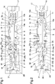
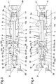
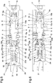
- Figures 1 to 6 are sectional views of a valve assembly according to the invention in different operating configurations.
- reference numeral 1 globally designates a valve assembly, particularly of the type of a brake-trailer valve.
- the valve assembly 1 comprises a body 2 inside which is obtained a seat 3 communicating with at least one supply port 4 connectable to a source of a pressurized work fluid, e.g. of the type of a gear pump, at least one braking port 6 connectable to the braking system of a trailer, and at least one drain port 7 connectable to a drain tank.
- a source of a pressurized work fluid e.g. of the type of a gear pump
- at least one braking port 6 connectable to the braking system of a trailer
- at least one drain port 7 connectable to a drain tank.
- the seat 3 is also communicating with at least one secondary port 5 connectable to at least one user point.
- the seat 3 preferably also has a driving port 8, which can be connected to another source of supply for the pressurized work fluid, e.g. of the type of a piston pump.
- At least one distributor 9 is housed in a sliding manner, which can be moved between a home position, in which the braking port 6 is isolated from the supply port 4 and is in communication with the drain port 7, and at least one braking position, in which the braking port 6 is in communication at least with the supply port 4.
- the distributor 9 is movable between a plurality of braking positions, in which the work fluid passage cross-section varies and, as a consequence, the braking pressure of the trailer also varies.
- the supply port 4 is placed in communication with the secondary port 5.
- At least one connecting channel 10 which is adapted to place the braking port 6 in communication with at least a first chamber 11, operating on the first end 9a of the distributor 9, and with at least a second chamber 12, operating on a second end 9b of the distributor 9 opposed to the first end 9a.
- the first chamber 11 is interposed between the first end 9a of the distributor 9 and a closure element 17 of the seat 3 associated to the body 2.
- the connecting channel 10 has a first section 10a communicating with the braking port 6, a second section 10b communicating with the first chamber 11, and a third section 10c communicating with the second chamber 12.
- a first orifice 13 between the first section 10a and the third section 10c there is a second orifice 14.
- the driving port 8 is adapted to be placed in communication with the second chamber 12 as a result of the displacement of the distributor 9 inside the seat 3.
- the distributor 9 comprises at least one driving channel 15 communicating with the connecting channel 10; the distributor 9 is adapted to place the driving channel 15 in communication with the driving port 8 during the displacement thereof inside the seat 3.
- the valve assembly 1 then comprises first elastic means 16 operating on the first end 9a and adapted to counteract the displacement of the distributor 9 from the home position towards a braking position.
- first elastic means 16 are housed inside the first chamber 11 and are interposed between the distributor 9 and the closure element 17.
- the first elastic means 16 are preferably made up of a single helical spring.
- Driving means 18 of the distributor 9 are also provided, which can be connected to the braking system of a towing vehicle and operating on the second end 9b to push the distributor itself from the home position towards a braking position.
- the driving means 18 comprise valve means 19 provided with at least one shutter element 20 adapted to place in communication/insulate the second chamber 12 with/from at least a third chamber 21 communicating with a further drain tank, wherein the valve means 19 comprise at least one connecting element 22 movable by the shutter element 20 and adapted to interact with the distributor 9.
- the connecting element 22 is locked together with the shutter element 20.
- Alternative embodiments cannot however be ruled out wherein a relative movement is provided, by a predefined stroke, between the shutter element 20 and the connecting element 22.
- the drain tank and the further drain tank may coincide or be separate from each other.
- the connecting element 22 is therefore protruding inside the second chamber 12.
- the shutter element 20 is therefore able to allow, choke or prevent the passage of the work fluid from the second chamber 12 to the third chamber 21.
- the shutter element 20 preferably has a substantially conical shape so as to involve a progressive increase in the passage of the work fluid as a result of its displacement.
- abutment element 23 locked together with the body 2 and which defines an abutment surface 23a against which the second end of the distributor 9 is leaning.
- the abutment surface 23a then defines an end-of-stroke position of the distributor 9.
- the abutment element 23 defines at least one opening 24 adapted to receive the shutter element 20.
- the opening 24 therefore faces the third chamber 21 and communicates with the second chamber 12.
- abutment element 23 there is one passage channel 25 adapted to place the opening 24 in communication with the second chamber 12.
- the opening 24 has at least one bottleneck 24a of the through type, inside which the connecting element 22 is inserted in a sliding manner.
- the connecting element 22 has a first end 22a locked together with the shutter element 20 and a second end 22b, opposed to the first end 22a, projecting inside the second chamber 12 and adapted to interact with the distributor 9.
- the connecting element 22 is of the type of a rod having an elongated shape.
- the connecting element 22 has a smaller cross-section than the cross-section of the opening 24.
- cross-section means the area defined by the connecting element 22 and by the opening 24 along a transverse plane to the relative longitudinal axis.
- both the connecting element 22 and the opening 24 have a substantially circular cross-section, where the diameter of the connecting element 22 is lower than the half of the diameter of the opening 24.
- second elastic means 26 which are housed inside the second chamber 12.
- the connecting element 22 moves towards the first end 9a of the distributor 9, the second elastic means 26 are then progressively compressed and the force they exert on the distributor itself increases.
- the second elastic means 26 are preferably made up of a single helical spring. More in particular, the second end 22b of the connecting element 22 is associated with a disc 27, which slides with respect to the distributor 9, and the second elastic means 26 are interposed between the disc 27 and the distributor 9.
- a retaining element 28, of the type of a Seeger ring, is locked together with the distributor 9 and against which the disc 27 leans. The retaining element 28 then defines the end-of-stroke position of the disc 27 as it moves away from the first end 9a of the distributor 9.
- the second elastic means 26 are of the pre-compressed type. Appropriately, the second elastic means 26 have greater load with respect to the first elastic means 16.
- the driving means 18 comprise at least one thrust element 29, connectable to the braking system of the towing vehicle, and third elastic means 30 interposed between the thrust element 29 and the shutter element 20.
- the thrust element 29 is then adapted to move towards the shutter element 20 as a result of the actuation of the braking pedal of the towing vehicle, compressing the third elastic means 30.
- the driving means 18 comprise at least one preload screw 31 locked together with the thrust element 29 and inserted in a sliding manner inside a spring guide element 32 associated with the shutter element 20 and around which the third elastic means 30 are fitted.
- the third elastic means 30 are preferably made up of a single helical spring.
- the operation of the present invention is as follows.
- the supply port 4 is placed in communication with the secondary port 5 and the braking port 6 is placed in communication with the drain port 7.
- the driving port 8 is also placed in communication with the drain port 7, through the driving channel 15 and the connecting channel 10.
- the second end 9b of the distributor 9 leans against the abutment surface 23a.
- the thrust element 29 moves in such a way as to compress the third elastic means 30, which then push the shutter element 20 closer to the opening 24.
- the displacement of the shutter element 20 also causes the displacement of the connecting element 22 which, by means of the disc 27, compresses the second elastic means 26.
- the second elastic means 26 which, as mentioned above, have greater load than the first elastic means 16, push the distributor 9 from the home position to a braking position.
- the displacement of the distributor 9 causes the closure of the connection between the braking port 6 and the drain port 7, as shown in Figure 2 .
- the further forward movement of the connecting element 22, in turn due to the displacement of the thrust element 29 and of the shutter element 20, causes the opening of the connection between the braking port itself and the supply port 4, thus allowing the pressurized work fluid to flow towards the braking system of the trailer, as shown in Figure 3 .
- the work fluid also enters the connecting channel 10 and flows into the first and second chambers 11 and 12 through the orifices 13 and 14.
- the work fluid in the second chamber 12 then enters the passage channel 25 and reaches the opening 24. As long as the shutter element 20 is spaced away from the opening 24, the work fluid passes through the latter, enters the third chamber 21 and is drained. In this operating condition, the pressure of the work fluid in the first and in the second chamber 11 and 12 is therefore substantially zero and only the forces exerted by the first and by the second elastic means 16 and 26 operate on the distributor 9.
- the shutter element 20 moves close to the opening 24 and chokes the flow of the work fluid inside the third chamber 21, the pressure inside the first chamber and the second chamber 11 and 12 increases and the forces generated by the pressure of the work fluid present in the chambers themselves therefore also operate on the distributor.
- the distributor 9 is free to displace to obtain the desired braking pressure.
- the shutter element 20 is pushed away from the opening 24 in order to drain at least part of the work fluid present in the second chamber 12.
- the pressure inside the second chamber 12 therefore decreases and the distributor 9, as a result of the higher pressure inside the first chamber 11, due to the presence of the orifices 13 and 14, moves closer to the abutment element 23, compressing the second elastic means 26.
- the shutter element 20 then moves closer to/further away from the opening 24 depending on the force exerted by the third elastic means 30 and by the pressure of the fluid in the second chamber 12.
- valve assembly to which the present invention relates allows the management of the braking pressure being released from the supply pressure of the work fluid.
- the use of the connecting element allows the force to be transferred from the driving means to the distributor and at the same time, having a reduced cross-section, it does not transfer sufficient force to unbalance the valve means/ distributor system.
- the passage channel which places the second chamber in communication with the opening facing the shutter element, allows the flow of the work fluid slowing down towards the opening itself and dampens the pulsations on the shutter element itself.
- the orifices along the connecting channel which slow down the variation of the work fluid contained in the first and in the second chambers, also contribute to the action of stabilizing the braking pressure.
Landscapes
- Engineering & Computer Science (AREA)
- Transportation (AREA)
- Mechanical Engineering (AREA)
- Physics & Mathematics (AREA)
- Fluid Mechanics (AREA)
- Lift Valve (AREA)
- Forging (AREA)
- Pens And Brushes (AREA)
Claims (15)
- Ventilbaugruppe (1), umfassend:- einen Körper (2), in dessen Inneren ein Sitz (3) ausgebildet ist, der mit mindestens einem Versorgungsanschluss (4) in Verbindung steht, der mit einer Quelle eines unter Druck stehenden Arbeitsfluids verbindbar ist, mindestens einem Bremsanschluss (6), der mit dem Bremssystem eines Anhängers verbindbar ist, mindestens einem Ablassanschluss (7), der mit einem Ablassbehälter verbindbar ist;- mindestens einen Verteiler (9), der gleitend innerhalb des Sitzes (3) untergebracht ist und zwischen einer Ausgangsstellung, in der der Bremsanschluss (6) von dem Versorgungsanschluss (4) isoliert ist und mit dem Ablassanschluss (7) in Verbindung steht, und mindestens einer Bremsstellung bewegbar ist, in der der Bremsanschluss (6) mindestens mit dem Versorgungsanschluss (4) in Verbindung steht;
wobei innerhalb des Verteilers (9) mindestens ein Verbindungskanal (10) ausgebildet ist, der ausgebildet ist, den Bremsanschluss (6) mit mindestens einer ersten Kammer (11), die auf ein erstes Ende (9a) des Verteilers (9) wirkt, und mit mindestens einer zweiten Kammer (12), die auf ein zweites Ende (9b) des Verteilers (9) wirkt, das dem ersten Ende (9a) gegenüberliegt, in Verbindung zu bringen;- erste elastische Mittel (16), die auf das erste Ende (9a) wirken und ausgebildet sind, der Verschiebung des Verteilers (9) aus der Ausgangsstellung in eine Bremsstellung entgegenzuwirken;- Antriebsmittel (18) des Verteilers (9), die mit dem Bremssystem eines Zugfahrzeugs verbindbar sind und auf das zweite Ende (9b) wirken, um den Verteiler (9) aus der Ausgangsstellung in eine Bremsstellung zu schieben;
gekennzeichnet durch die Tatsache, dass die Antriebsmittel (18) Ventilmittel (19) umfassen, die mit mindestens einem Verschlusselement (20) versehen sind, das ausgebildet ist, die zweite Kammer (12) in Verbindung mit/von mindestens einer dritten Kammer (21) zu bringen/ isolieren, die mit einem weiteren Ablassbehälter in Verbindung steht, und durch die Tatsache, dass die Ventilmittel (19) mindestens ein Verbindungselement (22) umfassen, das durch das Verschlusselement (20) beweglich ist und ausgebildet ist, mit dem Verteiler (9) zusammenzuwirken. - Ventilanordnung (1) nach Anspruch 1, dadurch gekennzeichnet, dass zwischen der zweiten Kammer (12) und der dritten Kammer (21) mindestens ein Anschlagelement (23) angeordnet ist, das mit dem Körper (2) verriegelt ist und mindestens eine Öffnung (24) definiert, die ausgebildet ist, das Verschlusselement (20) aufzunehmen, die der dritten Kammer (21) zugewandt ist und mit der zweiten Kammer (12) in Verbindung steht.
- Ventilanordnung (1) nach Anspruch 2, dadurch gekennzeichnet, dass das Anschlagelement (23) mindestens einen Durchgangskanal (25) aufweist, der ausgebildet ist, die Öffnung (24) mit der zweiten Kammer (12) in Verbindung zu bringen.
- Ventilanordnung (1) nach Anspruch 2 oder 3, dadurch gekennzeichnet, dass die Öffnung (24) mindestens einen durchgehenden Flaschenhals (24a) aufweist und dass das Verbindungselement (22) gleitend in dem Flaschenhals (24a) eingesetzt ist.
- Ventilanordnung (1) nach Anspruch 3, gekennzeichnet durch die Tatsache, dass der Querschnitt des Verbindungselements (22) kleiner ist als der Querschnitt der Öffnung (24).
- Ventilanordnung (1) nach Anspruch 4, dadurch gekennzeichnet, dass das Verbindungselement (22) und die Öffnung (24) einen im Wesentlichen kreisförmigen Querschnitt haben und dass der Durchmesser des Verbindungselements (22) kleiner ist als die Hälfte des Durchmessers der Öffnung (24).
- Ventilanordnung (1) nach einem oder mehreren der vorstehenden Ansprüche, dadurch gekennzeichnet, dass zwischen dem Verbindungselement (22) und dem Verteiler (9) zweite elastische Mittel (26) angeordnet sind.
- Ventilanordnung (1) nach Anspruch 7, gekennzeichnet durch die Tatsache, dass die zweiten elastischen Mittel (26) vom vorkomprimierten Typ sind und im Vergleich zu den ersten elastischen Mitteln (16) eine größere Spannung aufweisen.
- Ventilanordnung (1) nach einem oder mehreren der Ansprüche 2 bis 8, dadurch gekennzeichnet, dass das Anschlagelement (23) mindestens eine Anschlagfläche (23a) definiert, gegen die sich das zweite Ende (9b) des Verteilers (9) anlehnen kann.
- Ventilanordnung (1) nach einem oder mehreren der vorhergehenden Ansprüche, dadurch gekennzeichnet, dass das Verbindungselement (22) ein erstes Ende (22a), das mit dem Verschlusselement (20) verriegelt ist, und ein zweites Ende (22b) aufweist, das dem ersten Ende (22a) gegenüberliegt, in das Innere der zweiten Kammer (12) ragt und ausgebildet ist, mit dem Verteiler (9) zusammenzuwirken.
- Ventilanordnung (1) nach einem oder mehreren der vorstehenden Ansprüche, dadurch gekennzeichnet, dass das Verbindungselement (22) nach Art einer Stange mit länglicher Form ausgebildet ist.
- Ventilanordnung (1) nach einem oder mehreren der vorstehenden Ansprüche, dadurch gekennzeichnet, dass die Antriebsmittel (18) mindestens ein mit dem Bremssystem des Zugfahrzeugs verbindbares Schubelement (29) und dritte elastische Mittel (30) umfassen, die zwischen dem Schubelement (29) und dem Verschlusselement (20) angeordnet sind.
- Ventilanordnung (1) nach einem oder mehreren der vorstehenden Ansprüche, dadurch gekennzeichnet, dass der Verbindungskanal (10) mindestens einen ersten Abschnitt (10a), der mit dem Bremsanschluss (6) in Verbindung steht, mindestens einen zweiten Abschnitt (10b), der mit der ersten Kammer (11) in Verbindung steht, wobei zwischen dem ersten Abschnitt (10a) und dem zweiten Abschnitt (10b) eine erste Öffnung (13) angeordnet ist, und mindestens einen dritten Abschnitt (10c) umfasst, der mit der zweiten Kammer (12) in Verbindung steht, wobei zwischen dem ersten Abschnitt (10a) und dem dritten Abschnitt (10c) eine zweite Öffnung (14) angeordnet ist.
- Ventilanordnung (1) nach einem oder mehreren der vorhergehenden Ansprüche, dadurch gekennzeichnet, dass der Sitz (3) mit mindestens einem Antriebsanschluss (8) in Verbindung steht und dass der Verteiler (9) ausgebildet ist, während seiner Verschiebung innerhalb des Sitzes (3) den Antriebsanschluss (8) mit der zweiten Kammer (12) in Verbindung zu bringen.
- Ventilanordnung (1) nach Anspruch 14, dadurch gekennzeichnet, dass der Verteiler (9) mindestens einen Antriebskanal (15) aufweist, der mit dem Verbindungskanal (10) in Verbindung steht, wobei der Verteiler (9) ausgebildet ist, während seiner Verschiebung im Sitz (3) den Antriebskanal (15) mit dem Antriebsanschluss (8) in Verbindung zu bringen.
Applications Claiming Priority (1)
| Application Number | Priority Date | Filing Date | Title |
|---|---|---|---|
| IT102018000006900A IT201800006900A1 (it) | 2018-07-03 | 2018-07-03 | Blocco valvolare |
Publications (2)
| Publication Number | Publication Date |
|---|---|
| EP3590778A1 EP3590778A1 (de) | 2020-01-08 |
| EP3590778B1 true EP3590778B1 (de) | 2021-01-06 |
Family
ID=63896502
Family Applications (1)
| Application Number | Title | Priority Date | Filing Date |
|---|---|---|---|
| EP19183718.6A Active EP3590778B1 (de) | 2018-07-03 | 2019-07-01 | Ventilanordnung |
Country Status (2)
| Country | Link |
|---|---|
| EP (1) | EP3590778B1 (de) |
| IT (1) | IT201800006900A1 (de) |
Family Cites Families (7)
| Publication number | Priority date | Publication date | Assignee | Title |
|---|---|---|---|---|
| ES326457A1 (es) * | 1965-05-22 | 1967-03-01 | Renault | Dispositivo de mando del sistema de frenado de un remolque de vehiculo. |
| ITTO20010600A1 (it) * | 2001-06-21 | 2002-12-21 | Knorr Bremse Systeme | Gruppo valvolare, particolarmente per l'impiego nell'impianto pneumatico di frenatura di una motrice, per il controllo della frenatura di un |
| ITMO20110288A1 (it) * | 2011-11-11 | 2013-05-12 | Studio Tecnico 6M Srl | Dispositivo per la frenatura di un rimorchio |
| ITMO20120165A1 (it) * | 2012-06-28 | 2013-12-29 | Studio Tecnico 6M Srl | Dispositivo per la frenatura di un rimorchio |
| EP3000672B1 (de) * | 2014-05-30 | 2019-04-24 | SAFIM S.p.A. | Anhängerventilanordnung |
| ITMO20140333A1 (it) * | 2014-11-11 | 2016-05-11 | Safim S P A | Dispositivo per il controllo della frenatura di un rimorchio |
| ITUB20152034A1 (it) * | 2015-07-08 | 2017-01-08 | Safim S P A | Dispositivo di azionamento di una valvola per la frenatura di un rimorchio |
-
2018
- 2018-07-03 IT IT102018000006900A patent/IT201800006900A1/it unknown
-
2019
- 2019-07-01 EP EP19183718.6A patent/EP3590778B1/de active Active
Non-Patent Citations (1)
| Title |
|---|
| None * |
Also Published As
| Publication number | Publication date |
|---|---|
| IT201800006900A1 (it) | 2020-01-04 |
| EP3590778A1 (de) | 2020-01-08 |
Similar Documents
| Publication | Publication Date | Title |
|---|---|---|
| CN105358879B (zh) | 用于自动变速器的液压控制装置和自动变速器 | |
| RU2401390C2 (ru) | Диафрагменный насос и способ регулирования давления жидкости в диафрагменном насосе | |
| US10413430B2 (en) | Hydraulic damping cylinder, in particular for a knee prosthesis | |
| KR101497859B1 (ko) | 릴리프 밸브 | |
| KR102508991B1 (ko) | 브레이크 시스템 | |
| US5148834A (en) | Piston-type pressure accumulator for traction slip controlled brake systems and switching arrangement for same | |
| US11643061B2 (en) | Pedal simulation device with a plurality of return elements | |
| US10202988B2 (en) | Cushion mechanism for a hydraulic cylinder | |
| US7413264B2 (en) | Vehicle braking system | |
| EP3590778B1 (de) | Ventilanordnung | |
| EP2591963B1 (de) | Vorrichtung zum Bremsen eines Anhängers | |
| CN213109295U (zh) | 液压制动系统 | |
| US10774929B2 (en) | Hydraulic flushing valve arrangement | |
| US20170240155A1 (en) | Pump Attenuator Bypass Valve | |
| EP2119580A1 (de) | Stossdämpfer für Fahrzeuge, insbesondere für Motorrad-ähnliche Fahrzeuge und ähnlichen Fahrzeugen | |
| JPS5852854B2 (ja) | 流体圧ブレ−キブ−スタのための圧力制御装置 | |
| US3012509A (en) | Differential pumps | |
| CA2079137C (en) | Two-stage valve | |
| EP3401177B1 (de) | Anordnung zur steuerung eines anhängerbremsventils, zur kopplung mit einem bremssystem eines anhängerfahrzeugs. | |
| US10801615B2 (en) | Pressure limiting device, in particular for a hydraulic assist system for vehicles | |
| US4389167A (en) | Pump having membrane actuated control valve to unload slave actuated inlet valve | |
| EP1538045B1 (de) | Hydraulische Steuerung | |
| KR101546607B1 (ko) | 릴리프 밸브장치 | |
| CN119527263B (zh) | 一种制动阀 | |
| RU66463U1 (ru) | Двухступенчатый клапан давления |
Legal Events
| Date | Code | Title | Description |
|---|---|---|---|
| PUAI | Public reference made under article 153(3) epc to a published international application that has entered the european phase |
Free format text: ORIGINAL CODE: 0009012 |
|
| STAA | Information on the status of an ep patent application or granted ep patent |
Free format text: STATUS: THE APPLICATION HAS BEEN PUBLISHED |
|
| AK | Designated contracting states |
Kind code of ref document: A1 Designated state(s): AL AT BE BG CH CY CZ DE DK EE ES FI FR GB GR HR HU IE IS IT LI LT LU LV MC MK MT NL NO PL PT RO RS SE SI SK SM TR |
|
| AX | Request for extension of the european patent |
Extension state: BA ME |
|
| STAA | Information on the status of an ep patent application or granted ep patent |
Free format text: STATUS: REQUEST FOR EXAMINATION WAS MADE |
|
| GRAP | Despatch of communication of intention to grant a patent |
Free format text: ORIGINAL CODE: EPIDOSNIGR1 |
|
| STAA | Information on the status of an ep patent application or granted ep patent |
Free format text: STATUS: GRANT OF PATENT IS INTENDED |
|
| 17P | Request for examination filed |
Effective date: 20200626 |
|
| RBV | Designated contracting states (corrected) |
Designated state(s): AL AT BE BG CH CY CZ DE DK EE ES FI FR GB GR HR HU IE IS IT LI LT LU LV MC MK MT NL NO PL PT RO RS SE SI SK SM TR |
|
| INTG | Intention to grant announced |
Effective date: 20200731 |
|
| GRAS | Grant fee paid |
Free format text: ORIGINAL CODE: EPIDOSNIGR3 |
|
| GRAA | (expected) grant |
Free format text: ORIGINAL CODE: 0009210 |
|
| STAA | Information on the status of an ep patent application or granted ep patent |
Free format text: STATUS: THE PATENT HAS BEEN GRANTED |
|
| AK | Designated contracting states |
Kind code of ref document: B1 Designated state(s): AL AT BE BG CH CY CZ DE DK EE ES FI FR GB GR HR HU IE IS IT LI LT LU LV MC MK MT NL NO PL PT RO RS SE SI SK SM TR |
|
| REG | Reference to a national code |
Ref country code: GB Ref legal event code: FG4D |
|
| REG | Reference to a national code |
Ref country code: AT Ref legal event code: REF Ref document number: 1352028 Country of ref document: AT Kind code of ref document: T Effective date: 20210115 Ref country code: CH Ref legal event code: EP |
|
| REG | Reference to a national code |
Ref country code: DE Ref legal event code: R096 Ref document number: 602019002071 Country of ref document: DE |
|
| REG | Reference to a national code |
Ref country code: IE Ref legal event code: FG4D |
|
| REG | Reference to a national code |
Ref country code: CH Ref legal event code: PK Free format text: BERICHTIGUNGEN |
|
| RIN2 | Information on inventor provided after grant (corrected) |
Inventor name: MAMEI, ERONNE Inventor name: MAMEI, ENRICO Inventor name: MAMEI, ANDREA |
|
| RAP4 | Party data changed (patent owner data changed or rights of a patent transferred) |
Owner name: SAFIM S.R.L. |
|
| REG | Reference to a national code |
Ref country code: DE Ref legal event code: R081 Ref document number: 602019002071 Country of ref document: DE Owner name: SAFIM S.R.L., MODENA, IT Free format text: FORMER OWNER: SAFIM S.P.A., MODENA, IT |
|
| REG | Reference to a national code |
Ref country code: NL Ref legal event code: MP Effective date: 20210106 |
|
| REG | Reference to a national code |
Ref country code: AT Ref legal event code: MK05 Ref document number: 1352028 Country of ref document: AT Kind code of ref document: T Effective date: 20210106 |
|
| REG | Reference to a national code |
Ref country code: LT Ref legal event code: MG9D |
|
| PG25 | Lapsed in a contracting state [announced via postgrant information from national office to epo] |
Ref country code: LT Free format text: LAPSE BECAUSE OF FAILURE TO SUBMIT A TRANSLATION OF THE DESCRIPTION OR TO PAY THE FEE WITHIN THE PRESCRIBED TIME-LIMIT Effective date: 20210106 Ref country code: NO Free format text: LAPSE BECAUSE OF FAILURE TO SUBMIT A TRANSLATION OF THE DESCRIPTION OR TO PAY THE FEE WITHIN THE PRESCRIBED TIME-LIMIT Effective date: 20210406 Ref country code: PT Free format text: LAPSE BECAUSE OF FAILURE TO SUBMIT A TRANSLATION OF THE DESCRIPTION OR TO PAY THE FEE WITHIN THE PRESCRIBED TIME-LIMIT Effective date: 20210506 Ref country code: BG Free format text: LAPSE BECAUSE OF FAILURE TO SUBMIT A TRANSLATION OF THE DESCRIPTION OR TO PAY THE FEE WITHIN THE PRESCRIBED TIME-LIMIT Effective date: 20210406 Ref country code: HR Free format text: LAPSE BECAUSE OF FAILURE TO SUBMIT A TRANSLATION OF THE DESCRIPTION OR TO PAY THE FEE WITHIN THE PRESCRIBED TIME-LIMIT Effective date: 20210106 Ref country code: GR Free format text: LAPSE BECAUSE OF FAILURE TO SUBMIT A TRANSLATION OF THE DESCRIPTION OR TO PAY THE FEE WITHIN THE PRESCRIBED TIME-LIMIT Effective date: 20210407 Ref country code: FI Free format text: LAPSE BECAUSE OF FAILURE TO SUBMIT A TRANSLATION OF THE DESCRIPTION OR TO PAY THE FEE WITHIN THE PRESCRIBED TIME-LIMIT Effective date: 20210106 |
|
| PG25 | Lapsed in a contracting state [announced via postgrant information from national office to epo] |
Ref country code: SE Free format text: LAPSE BECAUSE OF FAILURE TO SUBMIT A TRANSLATION OF THE DESCRIPTION OR TO PAY THE FEE WITHIN THE PRESCRIBED TIME-LIMIT Effective date: 20210106 Ref country code: RS Free format text: LAPSE BECAUSE OF FAILURE TO SUBMIT A TRANSLATION OF THE DESCRIPTION OR TO PAY THE FEE WITHIN THE PRESCRIBED TIME-LIMIT Effective date: 20210106 Ref country code: LV Free format text: LAPSE BECAUSE OF FAILURE TO SUBMIT A TRANSLATION OF THE DESCRIPTION OR TO PAY THE FEE WITHIN THE PRESCRIBED TIME-LIMIT Effective date: 20210106 Ref country code: PL Free format text: LAPSE BECAUSE OF FAILURE TO SUBMIT A TRANSLATION OF THE DESCRIPTION OR TO PAY THE FEE WITHIN THE PRESCRIBED TIME-LIMIT Effective date: 20210106 Ref country code: AT Free format text: LAPSE BECAUSE OF FAILURE TO SUBMIT A TRANSLATION OF THE DESCRIPTION OR TO PAY THE FEE WITHIN THE PRESCRIBED TIME-LIMIT Effective date: 20210106 |
|
| PG25 | Lapsed in a contracting state [announced via postgrant information from national office to epo] |
Ref country code: IS Free format text: LAPSE BECAUSE OF FAILURE TO SUBMIT A TRANSLATION OF THE DESCRIPTION OR TO PAY THE FEE WITHIN THE PRESCRIBED TIME-LIMIT Effective date: 20210506 |
|
| REG | Reference to a national code |
Ref country code: DE Ref legal event code: R097 Ref document number: 602019002071 Country of ref document: DE |
|
| PG25 | Lapsed in a contracting state [announced via postgrant information from national office to epo] |
Ref country code: SM Free format text: LAPSE BECAUSE OF FAILURE TO SUBMIT A TRANSLATION OF THE DESCRIPTION OR TO PAY THE FEE WITHIN THE PRESCRIBED TIME-LIMIT Effective date: 20210106 Ref country code: EE Free format text: LAPSE BECAUSE OF FAILURE TO SUBMIT A TRANSLATION OF THE DESCRIPTION OR TO PAY THE FEE WITHIN THE PRESCRIBED TIME-LIMIT Effective date: 20210106 Ref country code: CZ Free format text: LAPSE BECAUSE OF FAILURE TO SUBMIT A TRANSLATION OF THE DESCRIPTION OR TO PAY THE FEE WITHIN THE PRESCRIBED TIME-LIMIT Effective date: 20210106 |
|
| PLBE | No opposition filed within time limit |
Free format text: ORIGINAL CODE: 0009261 |
|
| STAA | Information on the status of an ep patent application or granted ep patent |
Free format text: STATUS: NO OPPOSITION FILED WITHIN TIME LIMIT |
|
| PG25 | Lapsed in a contracting state [announced via postgrant information from national office to epo] |
Ref country code: DK Free format text: LAPSE BECAUSE OF FAILURE TO SUBMIT A TRANSLATION OF THE DESCRIPTION OR TO PAY THE FEE WITHIN THE PRESCRIBED TIME-LIMIT Effective date: 20210106 Ref country code: RO Free format text: LAPSE BECAUSE OF FAILURE TO SUBMIT A TRANSLATION OF THE DESCRIPTION OR TO PAY THE FEE WITHIN THE PRESCRIBED TIME-LIMIT Effective date: 20210106 Ref country code: SK Free format text: LAPSE BECAUSE OF FAILURE TO SUBMIT A TRANSLATION OF THE DESCRIPTION OR TO PAY THE FEE WITHIN THE PRESCRIBED TIME-LIMIT Effective date: 20210106 |
|
| 26N | No opposition filed |
Effective date: 20211007 |
|
| PG25 | Lapsed in a contracting state [announced via postgrant information from national office to epo] |
Ref country code: ES Free format text: LAPSE BECAUSE OF FAILURE TO SUBMIT A TRANSLATION OF THE DESCRIPTION OR TO PAY THE FEE WITHIN THE PRESCRIBED TIME-LIMIT Effective date: 20210106 Ref country code: AL Free format text: LAPSE BECAUSE OF FAILURE TO SUBMIT A TRANSLATION OF THE DESCRIPTION OR TO PAY THE FEE WITHIN THE PRESCRIBED TIME-LIMIT Effective date: 20210106 |
|
| REG | Reference to a national code |
Ref country code: DE Ref legal event code: R119 Ref document number: 602019002071 Country of ref document: DE |
|
| PG25 | Lapsed in a contracting state [announced via postgrant information from national office to epo] |
Ref country code: SI Free format text: LAPSE BECAUSE OF FAILURE TO SUBMIT A TRANSLATION OF THE DESCRIPTION OR TO PAY THE FEE WITHIN THE PRESCRIBED TIME-LIMIT Effective date: 20210106 |
|
| PG25 | Lapsed in a contracting state [announced via postgrant information from national office to epo] |
Ref country code: MC Free format text: LAPSE BECAUSE OF FAILURE TO SUBMIT A TRANSLATION OF THE DESCRIPTION OR TO PAY THE FEE WITHIN THE PRESCRIBED TIME-LIMIT Effective date: 20210106 |
|
| REG | Reference to a national code |
Ref country code: BE Ref legal event code: MM Effective date: 20210731 |
|
| PG25 | Lapsed in a contracting state [announced via postgrant information from national office to epo] |
Ref country code: DE Free format text: LAPSE BECAUSE OF NON-PAYMENT OF DUE FEES Effective date: 20220201 |
|
| PG25 | Lapsed in a contracting state [announced via postgrant information from national office to epo] |
Ref country code: IS Free format text: LAPSE BECAUSE OF FAILURE TO SUBMIT A TRANSLATION OF THE DESCRIPTION OR TO PAY THE FEE WITHIN THE PRESCRIBED TIME-LIMIT Effective date: 20210506 Ref country code: LU Free format text: LAPSE BECAUSE OF NON-PAYMENT OF DUE FEES Effective date: 20210701 |
|
| PG25 | Lapsed in a contracting state [announced via postgrant information from national office to epo] |
Ref country code: IE Free format text: LAPSE BECAUSE OF NON-PAYMENT OF DUE FEES Effective date: 20210701 Ref country code: BE Free format text: LAPSE BECAUSE OF NON-PAYMENT OF DUE FEES Effective date: 20210731 |
|
| REG | Reference to a national code |
Ref country code: CH Ref legal event code: PL |
|
| PG25 | Lapsed in a contracting state [announced via postgrant information from national office to epo] |
Ref country code: LI Free format text: LAPSE BECAUSE OF NON-PAYMENT OF DUE FEES Effective date: 20220731 Ref country code: CH Free format text: LAPSE BECAUSE OF NON-PAYMENT OF DUE FEES Effective date: 20220731 |
|
| PG25 | Lapsed in a contracting state [announced via postgrant information from national office to epo] |
Ref country code: NL Free format text: LAPSE BECAUSE OF NON-PAYMENT OF DUE FEES Effective date: 20210206 Ref country code: CY Free format text: LAPSE BECAUSE OF FAILURE TO SUBMIT A TRANSLATION OF THE DESCRIPTION OR TO PAY THE FEE WITHIN THE PRESCRIBED TIME-LIMIT Effective date: 20210106 |
|
| P01 | Opt-out of the competence of the unified patent court (upc) registered |
Effective date: 20230527 |
|
| PG25 | Lapsed in a contracting state [announced via postgrant information from national office to epo] |
Ref country code: HU Free format text: LAPSE BECAUSE OF FAILURE TO SUBMIT A TRANSLATION OF THE DESCRIPTION OR TO PAY THE FEE WITHIN THE PRESCRIBED TIME-LIMIT; INVALID AB INITIO Effective date: 20190701 |
|
| GBPC | Gb: european patent ceased through non-payment of renewal fee |
Effective date: 20230701 |
|
| PG25 | Lapsed in a contracting state [announced via postgrant information from national office to epo] |
Ref country code: MK Free format text: LAPSE BECAUSE OF FAILURE TO SUBMIT A TRANSLATION OF THE DESCRIPTION OR TO PAY THE FEE WITHIN THE PRESCRIBED TIME-LIMIT Effective date: 20210106 Ref country code: GB Free format text: LAPSE BECAUSE OF NON-PAYMENT OF DUE FEES Effective date: 20230701 |
|
| PG25 | Lapsed in a contracting state [announced via postgrant information from national office to epo] |
Ref country code: MT Free format text: LAPSE BECAUSE OF FAILURE TO SUBMIT A TRANSLATION OF THE DESCRIPTION OR TO PAY THE FEE WITHIN THE PRESCRIBED TIME-LIMIT Effective date: 20210106 |
|
| PGFP | Annual fee paid to national office [announced via postgrant information from national office to epo] |
Ref country code: IT Payment date: 20250721 Year of fee payment: 7 |
|
| PGFP | Annual fee paid to national office [announced via postgrant information from national office to epo] |
Ref country code: FR Payment date: 20250725 Year of fee payment: 7 |
|
| PG25 | Lapsed in a contracting state [announced via postgrant information from national office to epo] |
Ref country code: TR Free format text: LAPSE BECAUSE OF FAILURE TO SUBMIT A TRANSLATION OF THE DESCRIPTION OR TO PAY THE FEE WITHIN THE PRESCRIBED TIME-LIMIT Effective date: 20210106 |