EP3590686B1 - A device and a method for solvent vapor smoothing of a surface of a plastic product - Google Patents
A device and a method for solvent vapor smoothing of a surface of a plastic product Download PDFInfo
- Publication number
- EP3590686B1 EP3590686B1 EP18461571.4A EP18461571A EP3590686B1 EP 3590686 B1 EP3590686 B1 EP 3590686B1 EP 18461571 A EP18461571 A EP 18461571A EP 3590686 B1 EP3590686 B1 EP 3590686B1
- Authority
- EP
- European Patent Office
- Prior art keywords
- solvent
- chamber
- temperature
- evaporator
- vapors
- Prior art date
- Legal status (The legal status is an assumption and is not a legal conclusion. Google has not performed a legal analysis and makes no representation as to the accuracy of the status listed.)
- Active
Links
Images

Classifications
-
- B—PERFORMING OPERATIONS; TRANSPORTING
- B29—WORKING OF PLASTICS; WORKING OF SUBSTANCES IN A PLASTIC STATE IN GENERAL
- B29C—SHAPING OR JOINING OF PLASTICS; SHAPING OF MATERIAL IN A PLASTIC STATE, NOT OTHERWISE PROVIDED FOR; AFTER-TREATMENT OF THE SHAPED PRODUCTS, e.g. REPAIRING
- B29C71/00—After-treatment of articles without altering their shape; Apparatus therefor
- B29C71/0009—After-treatment of articles without altering their shape; Apparatus therefor using liquids, e.g. solvents, swelling agents
-
- B—PERFORMING OPERATIONS; TRANSPORTING
- B29—WORKING OF PLASTICS; WORKING OF SUBSTANCES IN A PLASTIC STATE IN GENERAL
- B29C—SHAPING OR JOINING OF PLASTICS; SHAPING OF MATERIAL IN A PLASTIC STATE, NOT OTHERWISE PROVIDED FOR; AFTER-TREATMENT OF THE SHAPED PRODUCTS, e.g. REPAIRING
- B29C64/00—Additive manufacturing, i.e. manufacturing of three-dimensional [3D] objects by additive deposition, additive agglomeration or additive layering, e.g. by 3D printing, stereolithography or selective laser sintering
- B29C64/30—Auxiliary operations or equipment
- B29C64/35—Cleaning
-
- B—PERFORMING OPERATIONS; TRANSPORTING
- B29—WORKING OF PLASTICS; WORKING OF SUBSTANCES IN A PLASTIC STATE IN GENERAL
- B29C—SHAPING OR JOINING OF PLASTICS; SHAPING OF MATERIAL IN A PLASTIC STATE, NOT OTHERWISE PROVIDED FOR; AFTER-TREATMENT OF THE SHAPED PRODUCTS, e.g. REPAIRING
- B29C64/00—Additive manufacturing, i.e. manufacturing of three-dimensional [3D] objects by additive deposition, additive agglomeration or additive layering, e.g. by 3D printing, stereolithography or selective laser sintering
- B29C64/30—Auxiliary operations or equipment
- B29C64/386—Data acquisition or data processing for additive manufacturing
- B29C64/393—Data acquisition or data processing for additive manufacturing for controlling or regulating additive manufacturing processes
-
- B—PERFORMING OPERATIONS; TRANSPORTING
- B33—ADDITIVE MANUFACTURING TECHNOLOGY
- B33Y—ADDITIVE MANUFACTURING, i.e. MANUFACTURING OF THREE-DIMENSIONAL [3-D] OBJECTS BY ADDITIVE DEPOSITION, ADDITIVE AGGLOMERATION OR ADDITIVE LAYERING, e.g. BY 3-D PRINTING, STEREOLITHOGRAPHY OR SELECTIVE LASER SINTERING
- B33Y40/00—Auxiliary operations or equipment, e.g. for material handling
- B33Y40/20—Post-treatment, e.g. curing, coating or polishing
-
- F—MECHANICAL ENGINEERING; LIGHTING; HEATING; WEAPONS; BLASTING
- F26—DRYING
- F26B—DRYING SOLID MATERIALS OR OBJECTS BY REMOVING LIQUID THEREFROM
- F26B21/00—Arrangements or duct systems, e.g. in combination with pallet boxes, for supplying and controlling air or gases for drying solid materials or objects
- F26B21/02—Circulating air or gases in closed cycles, e.g. wholly within the drying enclosure
-
- F—MECHANICAL ENGINEERING; LIGHTING; HEATING; WEAPONS; BLASTING
- F26—DRYING
- F26B—DRYING SOLID MATERIALS OR OBJECTS BY REMOVING LIQUID THEREFROM
- F26B3/00—Drying solid materials or objects by processes involving the application of heat
- F26B3/02—Drying solid materials or objects by processes involving the application of heat by convection, i.e. heat being conveyed from a heat source to the materials or objects to be dried by a gas or vapour, e.g. air
- F26B3/04—Drying solid materials or objects by processes involving the application of heat by convection, i.e. heat being conveyed from a heat source to the materials or objects to be dried by a gas or vapour, e.g. air the gas or vapour circulating over or surrounding the materials or objects to be dried
-
- F—MECHANICAL ENGINEERING; LIGHTING; HEATING; WEAPONS; BLASTING
- F26—DRYING
- F26B—DRYING SOLID MATERIALS OR OBJECTS BY REMOVING LIQUID THEREFROM
- F26B9/00—Machines or apparatus for drying solid materials or objects at rest or with only local agitation; Domestic airing cupboards
- F26B9/06—Machines or apparatus for drying solid materials or objects at rest or with only local agitation; Domestic airing cupboards in stationary drums or chambers
Definitions
- the present disclosure relates to a device and a method for solvent vapor smoothing of a surface of a plastic product.
- the present disclosure relates to smoothing of a surface of models made by additive manufacturing process utilizing melted polymer layers, by condensation of solvent vapors thereon.
- Products made by increasingly popular 3D printing technologies usually have a layered structure, which is visible by a naked eye.
- This relates in particular to Layer Plastic Deposition (LPD) technology, wherein a thermoplastic material (filament) is melted in an extruder and layered on a working platform, thereby creating a three-dimensional product.
- LPD Layer Plastic Deposition
- solvent vapor smoothing in which the product is treated with a solvent vapor which condenses on a surface of the product, thereby making it smoother.
- the process of solvent vapor smoothing of plastic products performed by the known devices and methods is typically a long lasting process in which highly concentrated solvents are used. This causes several problems. For example, it is difficult to avoid emission of harmful solvent vapors from the working chamber of the device to the ambient environment. Moreover, the smoothing process is not uniform and in some regions the product subject to the smoothing process tends to deform, while in other regions the surface is not smoothed to a satisfactory degree.
- Document US 2009/321972 A1 discloses a method for solvent vapor smoothing of a surface of a plastic product, the method comprising the steps of: placing the plastic product to be smoothed in a closed chamber; heating at least one wall of the chamber to a temperature and heating the evaporator to a temperature wherein the evaporator temperature is higher than the expected boiling temperature of the solvent for a current pressure within the chamber; introducing a solvent to the evaporator; allowing the solvent vapors to condense on the outer surface of the product; and collecting solvent vapors from the chamber.
- the method and device as defined above are particularly useful for improving the solvent vapor smoothing process with respect to the problem of preventing condensation of solvent on walls to improve the solvent concentration within the chamber and/or to avoid solvent dropping from the top wall towards the heated object, by generating a high temperature gradient between the product and solvent vapors before starting the vaporization.
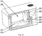
- Fig. 1a presents an example embodiment of a device for solvent vapor smoothing in an isometric view.
- the device comprises a chamber 110 closed by a sealed door 120.
- the chamber 110 is made of metal.
- a product to be smoothed is placed inside the chamber.
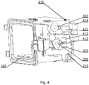
- the product is placed on a table 140 ( Fig. 4 ) having the table top located from 1cm to 5cm (preferably, 2 cm) above a bottom wall 112 of the chamber.
- the table 140 is preferably made of glass, but it may be also made of steel, aluminium or other suitable materials.
- An evaporator 111 is positioned at the bottom of the chamber, for example placed within the bottom wall 112.
- the evaporator 111 may have a form of an indentation, to which a portion of the solvent is transferred through a duct 212.
- the solvent may be transferred to the evaporator 111 under a force of gravity (i.e. without using a pump) from a main solvent tank 211 ( Fig. 2 ). This eliminates the need to use solvent-resistant pumps and requires only a solvent-resistant duct 212 to guide the solvent from the tank 211 to the evaporator 111.
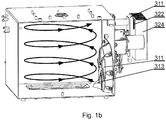
- the chamber 110 comprises a circulation system 300, for circulating solvent vapors.
- the circulation system 300 comprises a fan 311 having a nozzle 313 that influences the air within the chamber for circulating the solvent vapors inside the chamber 110 in a direction from the bottom to the top of the chamber 110 (as indicated in Fig. 1b ).
- the shape of the nozzle shall be preferably selected such as to cause a spiral-shaped flow of vapors inside the chamber. Such flow results in even concentration of vapors inside the chamber.
- the flow of solvent vapors allows the details and thin walls of the product to warm up faster, which reduces the amount of solvent that concentrates on these details and heat walls, thereby reducing their smoothing as compared to larger portions of the product.
- the flow of solvent vapors inside the chamber from the bottom towards the top opposes the gravity force and helps, at least to a small extent, to retain the original shape of the product during the solvent vapor smoothing process, when small elements (details) of the product tend to bend downwards under gravity due to the melting action of the solvent and the high temperature.
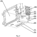
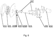
- the fan 311 is driven by a motor 312, which may be coupled by a belt transmission 316 with a driving shaft 314 protruding inside the chamber 110 through a sealed block 315.
- the sealed block 315 has a multistage sealing 317 and two crowns, wherein the first crown 315A allows to fit the sealed block to the chamber 110 providing air tightness and the second crown 315B allows the solvent to circulate towards the inside of the chamber 110. Details of the sealed block 315 and the driving shaft are presented in Fig. 6 .
- the device is controlled by means of a controller operable via a control panel 130, which allows the user of the device to adjust parameters of the smoothing process.
- a controller operable via a control panel 130, which allows the user of the device to adjust parameters of the smoothing process.
- the controller calculates the process parameters such as a temperature inside the chamber, an amount of the solvent to use, pressure etc.
- Fig. 2 presents the device in an isometric view, without a cover.
- the device comprises heating elements 220 distributed on an outer surface of at least one of the walls 112-116 for heating the interior of the chamber 110.
- the heating elements 220 may be provided on the outer surface of the bottom wall 112 and on the outer surface of a top wall 114.
- the device may further comprise heating elements 220 distributed on an outer surface of the side walls 113, 115, 116.
- a single element may be attached to a wall or a plurality of elements, e.g. 6 elements, may be arranged over the outer surface of the wall.
- At least one heating element 220 can be located directly under the evaporator 111, to effect the heating and evaporating of the solvent from the evaporator 111.
- the heating elements 220 located on the top wall 114 can be controlled by a first temperature sensor (e.g. a thermistor), the heating elements 220 located on the bottom wall 112 can be controlled by a second temperature sensor and the heating elements 220 located under the evaporator 111 can be controlled by a third temperature sensor.
- a first temperature sensor e.g. a thermistor
- the heating elements 220 located on the bottom wall 112 can be controlled by a second temperature sensor
- the heating elements 220 located under the evaporator 111 can be controlled by a third temperature sensor. This allows for independent operation of each group of the heating elements 220 in order to control the rate (intensity) of evaporation of the solvent and the temperature in the chamber 110. If the walls 112-116 of the chamber are made of a good heat conductor (for example, aluminiu
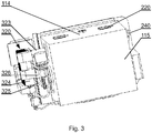
- Fig. 3 presents the device without the cover in a back view.
- the solvent stored in the main solvent tank 211 is gravitationally transferred to the evaporator 111 when a solvent dosing valve 213 is opened.
- a sensor for measuring a level of the solvent within the evaporator 111 may be located on an outer surface of the main solvent tank 211 to measure the amount of solvent within the evaporator 111.
- the sensor may be configured to start the measurement if the level of the solvent is above the minimum value required for a smoothing process to start.
- a sensor may be configured to provide only the information on whether the level of the solvent is above a predetermined level, wherein the amount of solvent may be calculated based on the duration of opening of the valve that doses the solvent.
- the amount of the transferred solvent depends on the process parameters, for example the size of the product, the type of the material it is made of, the desired degree of initial and final smoothness etc.
- Various solvents can be used, for example acetone, isopropyl alcohol, methyl ethyl ketone (MEK, 2-butanone).
- MEK methyl ethyl ketone
- the main solvent tank 211 may be filled up with the solvent through an opening 214 located at the front of the device.
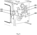
- the circulation system 300 further comprises a refrigerating module 320 which decreases the temperature of the solvent vapor in order to condense the solvent (in particular, after the smoothing process is finished).
- the condensed solvent is transferred gravitationally from the refrigerating module 320 to the main solvent tank 211 through a transfer tube 325.
- the refrigerating module 320 comprises an inlet 323 for collecting the air saturated with solvent vapors from the upper portion of the chamber 110 and transferring it to a cooling section 321 ( Fig. 5 ), and an outlet 326 for exhaling the dried air from the cooling section 321 back to the chamber 110.
- Inside the cooling section 321 there are located air ducts with multiple ribs 327 for condensing the solvent from the air.
- the plurality of ribs 327 increases the cooling surface of the cooling section 321.
- the refrigerating module 320 may comprise Peltier modules 322 which decrease the temperature of inner surfaces of the cooling section 321, to achieve a dew point for a particular concentration of the solvent in the air within the chamber (i.e. a temperature at which the air is saturated by the solvent vapor).
- a heat sink 324 is connected to the warm side of the Peltier modules in order to dissipate the heat away from the refrigerating module 320.
- the heat sink 324 is additionally cooled down by means of two or more cooling fans attached to an inner side of the cover of the device (the fans are not shown in the drawings).
- the temperature of the warm side of the refrigerating module 320 is controlled by a temperature sensor coupled with the heat sink 324, while the temperature of the cold side of the refrigerating module 320 is controlled by a temperature sensor coupled with the cooling section 321.
- the cold side of the refrigerating module 320 can be covered with a layer of a closed cell foam which prevents condensing of water vapor, present in the air, on an outer surface of the refrigerating module 320.
- the foam provides heat insulation and eliminates condensed water vapor from influencing the thermal capacity of the cooling section 321.
- the circulation system 300 circulates solvent vapors inside the chamber 110 in a direction from the bottom to a top of the chamber 110 and outside the chamber in a direction from the top to the bottom of the chamber 110 in a closed loop system (wherein the vapors are preferably cooled and condensed to be guided to a main solvent tank 211 and then transferred as liquid solvent to the evaporator 111).
- Fig. 4 presents the device without the cover and without the refrigerating system in an isometric view.
- the device further comprises a pressure module 410 comprising a pressure valve 411 for blocking an exchange of pressure between the chamber 110 and an outer environment, a Tee fitting 412 with one end connected to the pressure valve 411, a second end connected to a vent valve 413 and a third end connected to a vacuum pump 414.
- the vacuum pump 414 is used to produce the negative pressure in the chamber 110 before the smoothing process is started.
- the value of the negative pressure in the chamber is measured by the strain gauge 240 mounted on an outer surface of the side wall of the chamber 110, for example mounted at an angle of 45° in the corner on the outer side of a side wall 116.
- the strain gauge 240 measures the deformation of the metal sheet of the side wall of the chamber 110.
- Use of the strain gauge as a pressure sensor provides faster response to pressure changes inside the chamber comparing to standard pressure sensors. It also eliminates the necessity of utilizing pressure sensors resistant to environments with an explosive atmosphere.
- All elements of the device which are in contact with the solvent or solvent vapors shall be made of solvent-resistant materials, to maintain long lifetime of the device.
- Fig. 7 presents a solvent vapor smoothing process.
- a product is placed inside the chamber 110, the door 120 is closed and process parameters are determined, based on input data including: a type of geometry of the model (e.g. simple or complex), a material of the product, a type of solvent and a desired intensity of the smoothing effect etc.
- the process parameters that are determined accordingly include the amount of solvent to use in the process, the amount of the negative pressure to be generated, the heating temperatures of the side walls and the evaporator etc.
- a skilled person will realize how to calculate the process parameters based on generals rules of physics, e.g. the higher the desired smoothing effect, the higher solvent concentration shall be used.
- the expected dew point and the evaporation temperature of the solvent can be calculated based on the negative pressure that is to be initially generated within the chamber and the amount of solvent that is to be introduced.
- the door 120 is secured to prevent opening of the door during the process, which could cause toxic vapors to escape from the chamber.
- the door can be secured with an electromagnetic lock.
- the vacuum pump 414 is started to generate the negative pressure in the chamber.
- the negative pressure has a value from 300 to 800 mbar with respect to the ambient pressure (wherein the pressure of the ambient environment of the device is typically the atmospheric pressure), i.e. it is lower from the ambient pressure by 300 to 800 mbar.
- the negative pressure protects the chamber from depressurization (leaking) due to the subsequent increase of pressure during solvent vaporization which takes place further in the process.
- the generated negative pressure facilitates the heating of the chamber walls, in particular the top wall and the bottom wall, without significant heating of the product and therefore facilitates generating a high temperature gradient between the product and solvent vapors before starting the vaporization.
- the heated walls prevent condensation of the solvent vapors on their surface, which would decrease the solvent concentration in the chamber. Furthermore condensing of the solvent vapors on the top wall of the chamber could result in solvent dropping on the models, which could jeopardize results of the smoothing process.
- step 503 after achieving a desired value of the negative pressure, the heating of the chamber walls and the evaporator 111 is initiated.
- At least one wall preferably at least the top wall 114, is heated to a first temperature, which is higher than the expected dew point temperature of the solvent, and preferably lower than the expected boiling temperature of the solvent.
- the bottom wall 112 and the side walls 113, 115, 116 are preferably heated by the heating elements 220 as well.
- the walls 112-116 are heated by means of thermal conduction of the wall material that transfers heat along the walls from the heating elements.
- At least a portion of the evaporator 111 is heated to a second temperature, which is higher than the expected boiling temperature of the solvent.
- step 504 the solvent is introduced into the evaporator 111, so that it evaporates as a result of the high temperature of the evaporator 111.
- the amount of the introduced solvent which is proportional to an opening duration of the dosing valve 213, depends on the desired smoothing level, for example it may be from 50 to 300 ml for a chamber working volume equal from 40 to 50 litters.
- step 505 the evaporated solvent is distributed by the circulation system (from the bottom to the top of the chamber) and by means of convection.
- the power of the circulation system may be controlled in order to adjust the rotational velocity of the fan which directly influences the speed of flow of the solvent vapors.
- step 506 the outer surface of the product is smoothed due to the solvent condensing on the surface of the product.
- the condensation occurs due to the fact that the temperature of the product outer surface is lower than the temperature of solvent vapors. Heating of the walls causes heating of the air inside the chamber and consequently gradual heating of the surface of the product.
- the smoothing process is stopped, because the solvent stops condensing on the product surface.
- the smoothing step may last from 5 to 20 min. Most of the smoothed products have a complicated geometry, with regions of greater volumes and thin-wall elements of a smaller volume which tend to warm up faster, and therefore the time during which they react with the solvent is shorter.
- the circulation system may operate periodically or continuously (optionally with variable operating power) during the smoothing step.
- the heating elements 220 can be still active to maintain the initial temperatures.
- the heating elements 220 are activated in order to heat up at least one of the walls to a third temperature which is higher than the first temperature, preferably higher than the expected boiling temperature of the solvent, thereby to heat the air and the product inside the chamber. This allows to quickly evaporate the reacted solvent from the surface of the product and from the surface of the chamber walls. The evaporation of the solvent is enhanced by the negative pressure within the chamber.
- step 508 the solvent vapors flow through the refrigerating unit.
- the inner surfaces of the cooling module are cooled below the dew point temperature for the particular concentration and pressure of the solvent.
- the solvent condenses on the walls of the cooling section and gravitationally flows down to the main solvent tank 211.
- the heating elements can be operated with less than 100% of their maximum power, for example with 50% of their power.
- the step of heating the chamber 507 and the step of cooling the solvent vapors 508 may be performed in an opposite order.
- the steps 507 and 508 or 508 and 507 may be sequentially repeated until the desired solvent concentration is achieved.
- the desired solvent concentration for acetone or 2-butanone may be below 40% of the lower flammability limit.
- step 509 the temperature inside the chamber is equalized with the room temperature.
- step 510 after the chamber is cooled down, the vent valve is opened to equalize the pressure and the electromagnetic lock is opened. Subsequently the door may be opened and the smoothed product may be taken out from the chamber.
- a tape which is resistant to the solvent may be used to mask the regions which are to remain intact during the smoothing process.
- the presented device and the method are safe for a user and the environment, because the hazard of an explosion or a risk for the solvent escaping from the chamber is significantly limited.
Landscapes
- Engineering & Computer Science (AREA)
- Chemical & Material Sciences (AREA)
- Materials Engineering (AREA)
- Mechanical Engineering (AREA)
- Manufacturing & Machinery (AREA)
- Physics & Mathematics (AREA)
- Optics & Photonics (AREA)
- General Engineering & Computer Science (AREA)
- Life Sciences & Earth Sciences (AREA)
- Microbiology (AREA)
- Vaporization, Distillation, Condensation, Sublimation, And Cold Traps (AREA)
- Drying Of Solid Materials (AREA)
Priority Applications (6)
| Application Number | Priority Date | Filing Date | Title |
|---|---|---|---|
| PL18461571T PL3590686T3 (pl) | 2018-07-02 | 2018-07-02 | Urządzenie i sposób wygładzania powierzchni wyrobu z tworzywa sztucznego parami rozpuszczalnika |
| EP18461571.4A EP3590686B1 (en) | 2018-07-02 | 2018-07-02 | A device and a method for solvent vapor smoothing of a surface of a plastic product |
| ES18461571T ES2880200T3 (es) | 2018-07-02 | 2018-07-02 | Un dispositivo y un método para alisar con vapor de disolvente una superficie de un producto plástico |
| CN201880000770.2A CN110933936B (zh) | 2018-07-02 | 2018-07-03 | 用于对塑料制品的表面进行溶剂蒸气平滑化的装置和方法 |
| PCT/EP2018/067859 WO2020007443A1 (en) | 2018-07-02 | 2018-07-03 | A device and a method for solvent vapor smoothing of a surface of a plastic product |
| US16/068,340 US11186051B2 (en) | 2018-07-02 | 2018-07-03 | Device and a method for solvent vapor smoothing of a surface of a plastic product |
Applications Claiming Priority (1)
| Application Number | Priority Date | Filing Date | Title |
|---|---|---|---|
| EP18461571.4A EP3590686B1 (en) | 2018-07-02 | 2018-07-02 | A device and a method for solvent vapor smoothing of a surface of a plastic product |
Publications (2)
| Publication Number | Publication Date |
|---|---|
| EP3590686A1 EP3590686A1 (en) | 2020-01-08 |
| EP3590686B1 true EP3590686B1 (en) | 2021-04-07 |
Family
ID=62837913
Family Applications (1)
| Application Number | Title | Priority Date | Filing Date |
|---|---|---|---|
| EP18461571.4A Active EP3590686B1 (en) | 2018-07-02 | 2018-07-02 | A device and a method for solvent vapor smoothing of a surface of a plastic product |
Country Status (6)
| Country | Link |
|---|---|
| US (1) | US11186051B2 (pl) |
| EP (1) | EP3590686B1 (pl) |
| CN (1) | CN110933936B (pl) |
| ES (1) | ES2880200T3 (pl) |
| PL (1) | PL3590686T3 (pl) |
| WO (1) | WO2020007443A1 (pl) |
Families Citing this family (4)
| Publication number | Priority date | Publication date | Assignee | Title |
|---|---|---|---|---|
| GB2584834A (en) * | 2019-06-10 | 2020-12-23 | Additive Manufacturing Tech Ltd | Additive manufacturing |
| EP3825108A1 (de) | 2019-11-20 | 2021-05-26 | WashTec Holding GmbH | Verfahren zur behandlung eines formartikels aus kunststoff |
| GB2597240B (en) * | 2020-07-06 | 2022-11-09 | Additive Manufacturing Tech Ltd | Improved method of solvent recovery |
| PL4225560T3 (pl) | 2020-10-09 | 2025-07-28 | Carbon, Inc. | Parowe czyszczenie wirowe części wytwarzanych przyrostowo |
Family Cites Families (13)
| Publication number | Priority date | Publication date | Assignee | Title |
|---|---|---|---|---|
| US4455135A (en) * | 1980-12-23 | 1984-06-19 | Bitterly Jack G | Vacuum chamber and method of creating a vacuum |
| US5448838A (en) * | 1993-09-14 | 1995-09-12 | Hess, Inc. | Apparatus for restoring plastic surfaces |
| FR2734501B1 (fr) * | 1995-05-23 | 1997-07-04 | Stein Heurtey | Procede et dispositif de revetement de bandes metalliques |
| RU2345888C2 (ru) * | 2002-04-17 | 2009-02-10 | Стратасис, Инк. | Способ выравнивания при моделировании методом наслоения |
| US8765045B2 (en) * | 2007-01-12 | 2014-07-01 | Stratasys, Inc. | Surface-treatment method for rapid-manufactured three-dimensional objects |
| US8075300B2 (en) * | 2008-06-30 | 2011-12-13 | Stratasys, Inc. | Vapor smoothing surface finishing system |
| US9086237B2 (en) * | 2012-02-09 | 2015-07-21 | Carrier Corporation | Vacuum drying of heat exchanger tubes |
| CN103192524A (zh) * | 2013-04-23 | 2013-07-10 | 苏州华漫信息服务有限公司 | 一种新的3d打印物体表面处理工艺 |
| JP5650807B2 (ja) * | 2013-06-13 | 2015-01-07 | ファナック株式会社 | 射出成形機の温度監視装置 |
| CN204526140U (zh) * | 2014-09-18 | 2015-08-05 | 孙韶 | 三维打印塑料、树脂件抛光设备 |
| CN205386940U (zh) * | 2016-02-05 | 2016-07-20 | 厦门三维天空信息科技有限公司 | 一种表面处理装置 |
| RU2625848C1 (ru) * | 2016-04-07 | 2017-07-19 | Общество с ограниченной ответственностью "Уфа Механика" | Устройство для автоматизированной финишной обработки изделий, изготовленных 3d печатью |
| GB201700346D0 (en) * | 2017-01-09 | 2017-02-22 | Additive Mfg Tech Ltd | Improvements to additive manufacturing |
-
2018
- 2018-07-02 PL PL18461571T patent/PL3590686T3/pl unknown
- 2018-07-02 ES ES18461571T patent/ES2880200T3/es active Active
- 2018-07-02 EP EP18461571.4A patent/EP3590686B1/en active Active
- 2018-07-03 WO PCT/EP2018/067859 patent/WO2020007443A1/en not_active Ceased
- 2018-07-03 US US16/068,340 patent/US11186051B2/en active Active
- 2018-07-03 CN CN201880000770.2A patent/CN110933936B/zh not_active Expired - Fee Related
Non-Patent Citations (1)
| Title |
|---|
| None * |
Also Published As
| Publication number | Publication date |
|---|---|
| US11186051B2 (en) | 2021-11-30 |
| CN110933936B (zh) | 2022-05-03 |
| CN110933936A (zh) | 2020-03-27 |
| EP3590686A1 (en) | 2020-01-08 |
| ES2880200T3 (es) | 2021-11-23 |
| PL3590686T3 (pl) | 2021-11-08 |
| US20210114321A1 (en) | 2021-04-22 |
| WO2020007443A1 (en) | 2020-01-09 |
Similar Documents
| Publication | Publication Date | Title |
|---|---|---|
| US11186052B2 (en) | Modular device and a method for smoothing of a surface of a plastic product | |
| EP3590686B1 (en) | A device and a method for solvent vapor smoothing of a surface of a plastic product | |
| EP3590693B1 (en) | A desktop device and a method for post-processing of a plastic product | |
| EP3876798B1 (en) | Steam cooking apparatus | |
| KR102658455B1 (ko) | 냉온장고, 및 진공단열체 | |
| US4615178A (en) | Apparatus and method for controlling a vacuum cooler | |
| JP2007032902A (ja) | 加熱調理器 | |
| US20240215748A1 (en) | Steam cooking apparatus | |
| TW201906655A (zh) | 用於溶劑萃取之系統及方法 | |
| EP3588079A1 (en) | Apparatus equipped with sample temperature control function | |
| TWI607189B (zh) | Heating conditioner | |
| HK40022371B (en) | A modular device and a method for smoothing of a surface of a plastic product | |
| HK40022371A (en) | A modular device and a method for smoothing of a surface of a plastic product | |
| HK40022375B (en) | A device and a method for solvent vapor smoothing of a surface of a plastic product | |
| HK40022375A (en) | A device and a method for solvent vapor smoothing of a surface of a plastic product | |
| HK40022372A (en) | A desktop device and a method for post-processing of a plastic product | |
| HK40022372B (en) | A desktop device and a method for post-processing of a plastic product | |
| TWI614458B (zh) | 高頻加熱調理器 | |
| JP4191064B2 (ja) | 蒸気調理器 | |
| JP5096503B2 (ja) | 環境試験装置 |
Legal Events
| Date | Code | Title | Description |
|---|---|---|---|
| PUAI | Public reference made under article 153(3) epc to a published international application that has entered the european phase |
Free format text: ORIGINAL CODE: 0009012 |
|
| STAA | Information on the status of an ep patent application or granted ep patent |
Free format text: STATUS: THE APPLICATION HAS BEEN PUBLISHED |
|
| AK | Designated contracting states |
Kind code of ref document: A1 Designated state(s): AL AT BE BG CH CY CZ DE DK EE ES FI FR GB GR HR HU IE IS IT LI LT LU LV MC MK MT NL NO PL PT RO RS SE SI SK SM TR |
|
| AX | Request for extension of the european patent |
Extension state: BA ME |
|
| STAA | Information on the status of an ep patent application or granted ep patent |
Free format text: STATUS: REQUEST FOR EXAMINATION WAS MADE |
|
| 17P | Request for examination filed |
Effective date: 20200708 |
|
| RBV | Designated contracting states (corrected) |
Designated state(s): AL AT BE BG CH CY CZ DE DK EE ES FI FR GB GR HR HU IE IS IT LI LT LU LV MC MK MT NL NO PL PT RO RS SE SI SK SM TR |
|
| RIC1 | Information provided on ipc code assigned before grant |
Ipc: B29C 71/00 20060101ALI20200831BHEP Ipc: B33Y 40/00 20200101ALI20200831BHEP Ipc: B29C 64/35 20170101AFI20200831BHEP |
|
| GRAP | Despatch of communication of intention to grant a patent |
Free format text: ORIGINAL CODE: EPIDOSNIGR1 |
|
| STAA | Information on the status of an ep patent application or granted ep patent |
Free format text: STATUS: GRANT OF PATENT IS INTENDED |
|
| INTG | Intention to grant announced |
Effective date: 20201026 |
|
| GRAS | Grant fee paid |
Free format text: ORIGINAL CODE: EPIDOSNIGR3 |
|
| GRAA | (expected) grant |
Free format text: ORIGINAL CODE: 0009210 |
|
| STAA | Information on the status of an ep patent application or granted ep patent |
Free format text: STATUS: THE PATENT HAS BEEN GRANTED |
|
| AK | Designated contracting states |
Kind code of ref document: B1 Designated state(s): AL AT BE BG CH CY CZ DE DK EE ES FI FR GB GR HR HU IE IS IT LI LT LU LV MC MK MT NL NO PL PT RO RS SE SI SK SM TR |
|
| REG | Reference to a national code |
Ref country code: GB Ref legal event code: FG4D |
|
| REG | Reference to a national code |
Ref country code: CH Ref legal event code: EP Ref country code: AT Ref legal event code: REF Ref document number: 1379115 Country of ref document: AT Kind code of ref document: T Effective date: 20210415 |
|
| REG | Reference to a national code |
Ref country code: DE Ref legal event code: R096 Ref document number: 602018015130 Country of ref document: DE |
|
| REG | Reference to a national code |
Ref country code: IE Ref legal event code: FG4D |
|
| REG | Reference to a national code |
Ref country code: NL Ref legal event code: FP |
|
| REG | Reference to a national code |
Ref country code: LT Ref legal event code: MG9D |
|
| REG | Reference to a national code |
Ref country code: SE Ref legal event code: TRGR |
|
| REG | Reference to a national code |
Ref country code: AT Ref legal event code: MK05 Ref document number: 1379115 Country of ref document: AT Kind code of ref document: T Effective date: 20210407 |
|
| PG25 | Lapsed in a contracting state [announced via postgrant information from national office to epo] |
Ref country code: LT Free format text: LAPSE BECAUSE OF FAILURE TO SUBMIT A TRANSLATION OF THE DESCRIPTION OR TO PAY THE FEE WITHIN THE PRESCRIBED TIME-LIMIT Effective date: 20210407 Ref country code: HR Free format text: LAPSE BECAUSE OF FAILURE TO SUBMIT A TRANSLATION OF THE DESCRIPTION OR TO PAY THE FEE WITHIN THE PRESCRIBED TIME-LIMIT Effective date: 20210407 Ref country code: FI Free format text: LAPSE BECAUSE OF FAILURE TO SUBMIT A TRANSLATION OF THE DESCRIPTION OR TO PAY THE FEE WITHIN THE PRESCRIBED TIME-LIMIT Effective date: 20210407 Ref country code: BG Free format text: LAPSE BECAUSE OF FAILURE TO SUBMIT A TRANSLATION OF THE DESCRIPTION OR TO PAY THE FEE WITHIN THE PRESCRIBED TIME-LIMIT Effective date: 20210707 Ref country code: AT Free format text: LAPSE BECAUSE OF FAILURE TO SUBMIT A TRANSLATION OF THE DESCRIPTION OR TO PAY THE FEE WITHIN THE PRESCRIBED TIME-LIMIT Effective date: 20210407 |
|
| REG | Reference to a national code |
Ref country code: ES Ref legal event code: FG2A Ref document number: 2880200 Country of ref document: ES Kind code of ref document: T3 Effective date: 20211123 |
|
| PG25 | Lapsed in a contracting state [announced via postgrant information from national office to epo] |
Ref country code: RS Free format text: LAPSE BECAUSE OF FAILURE TO SUBMIT A TRANSLATION OF THE DESCRIPTION OR TO PAY THE FEE WITHIN THE PRESCRIBED TIME-LIMIT Effective date: 20210407 Ref country code: LV Free format text: LAPSE BECAUSE OF FAILURE TO SUBMIT A TRANSLATION OF THE DESCRIPTION OR TO PAY THE FEE WITHIN THE PRESCRIBED TIME-LIMIT Effective date: 20210407 Ref country code: NO Free format text: LAPSE BECAUSE OF FAILURE TO SUBMIT A TRANSLATION OF THE DESCRIPTION OR TO PAY THE FEE WITHIN THE PRESCRIBED TIME-LIMIT Effective date: 20210707 Ref country code: PT Free format text: LAPSE BECAUSE OF FAILURE TO SUBMIT A TRANSLATION OF THE DESCRIPTION OR TO PAY THE FEE WITHIN THE PRESCRIBED TIME-LIMIT Effective date: 20210809 Ref country code: GR Free format text: LAPSE BECAUSE OF FAILURE TO SUBMIT A TRANSLATION OF THE DESCRIPTION OR TO PAY THE FEE WITHIN THE PRESCRIBED TIME-LIMIT Effective date: 20210708 Ref country code: IS Free format text: LAPSE BECAUSE OF FAILURE TO SUBMIT A TRANSLATION OF THE DESCRIPTION OR TO PAY THE FEE WITHIN THE PRESCRIBED TIME-LIMIT Effective date: 20210807 |
|
| REG | Reference to a national code |
Ref country code: DE Ref legal event code: R097 Ref document number: 602018015130 Country of ref document: DE |
|
| PG25 | Lapsed in a contracting state [announced via postgrant information from national office to epo] |
Ref country code: EE Free format text: LAPSE BECAUSE OF FAILURE TO SUBMIT A TRANSLATION OF THE DESCRIPTION OR TO PAY THE FEE WITHIN THE PRESCRIBED TIME-LIMIT Effective date: 20210407 Ref country code: SK Free format text: LAPSE BECAUSE OF FAILURE TO SUBMIT A TRANSLATION OF THE DESCRIPTION OR TO PAY THE FEE WITHIN THE PRESCRIBED TIME-LIMIT Effective date: 20210407 Ref country code: SM Free format text: LAPSE BECAUSE OF FAILURE TO SUBMIT A TRANSLATION OF THE DESCRIPTION OR TO PAY THE FEE WITHIN THE PRESCRIBED TIME-LIMIT Effective date: 20210407 Ref country code: RO Free format text: LAPSE BECAUSE OF FAILURE TO SUBMIT A TRANSLATION OF THE DESCRIPTION OR TO PAY THE FEE WITHIN THE PRESCRIBED TIME-LIMIT Effective date: 20210407 Ref country code: CZ Free format text: LAPSE BECAUSE OF FAILURE TO SUBMIT A TRANSLATION OF THE DESCRIPTION OR TO PAY THE FEE WITHIN THE PRESCRIBED TIME-LIMIT Effective date: 20210407 Ref country code: DK Free format text: LAPSE BECAUSE OF FAILURE TO SUBMIT A TRANSLATION OF THE DESCRIPTION OR TO PAY THE FEE WITHIN THE PRESCRIBED TIME-LIMIT Effective date: 20210407 |
|
| PLBE | No opposition filed within time limit |
Free format text: ORIGINAL CODE: 0009261 |
|
| STAA | Information on the status of an ep patent application or granted ep patent |
Free format text: STATUS: NO OPPOSITION FILED WITHIN TIME LIMIT |
|
| 26N | No opposition filed |
Effective date: 20220110 |
|
| PG25 | Lapsed in a contracting state [announced via postgrant information from national office to epo] |
Ref country code: MC Free format text: LAPSE BECAUSE OF FAILURE TO SUBMIT A TRANSLATION OF THE DESCRIPTION OR TO PAY THE FEE WITHIN THE PRESCRIBED TIME-LIMIT Effective date: 20210407 |
|
| PG25 | Lapsed in a contracting state [announced via postgrant information from national office to epo] |
Ref country code: IS Free format text: LAPSE BECAUSE OF FAILURE TO SUBMIT A TRANSLATION OF THE DESCRIPTION OR TO PAY THE FEE WITHIN THE PRESCRIBED TIME-LIMIT Effective date: 20210807 Ref country code: LU Free format text: LAPSE BECAUSE OF NON-PAYMENT OF DUE FEES Effective date: 20210702 Ref country code: AL Free format text: LAPSE BECAUSE OF FAILURE TO SUBMIT A TRANSLATION OF THE DESCRIPTION OR TO PAY THE FEE WITHIN THE PRESCRIBED TIME-LIMIT Effective date: 20210407 |
|
| PG25 | Lapsed in a contracting state [announced via postgrant information from national office to epo] |
Ref country code: IE Free format text: LAPSE BECAUSE OF NON-PAYMENT OF DUE FEES Effective date: 20210702 |
|
| PG25 | Lapsed in a contracting state [announced via postgrant information from national office to epo] |
Ref country code: CY Free format text: LAPSE BECAUSE OF FAILURE TO SUBMIT A TRANSLATION OF THE DESCRIPTION OR TO PAY THE FEE WITHIN THE PRESCRIBED TIME-LIMIT Effective date: 20210407 |
|
| PG25 | Lapsed in a contracting state [announced via postgrant information from national office to epo] |
Ref country code: HU Free format text: LAPSE BECAUSE OF FAILURE TO SUBMIT A TRANSLATION OF THE DESCRIPTION OR TO PAY THE FEE WITHIN THE PRESCRIBED TIME-LIMIT; INVALID AB INITIO Effective date: 20180702 |
|
| PGFP | Annual fee paid to national office [announced via postgrant information from national office to epo] |
Ref country code: NL Payment date: 20230726 Year of fee payment: 6 |
|
| PGFP | Annual fee paid to national office [announced via postgrant information from national office to epo] |
Ref country code: IT Payment date: 20230720 Year of fee payment: 6 Ref country code: GB Payment date: 20230727 Year of fee payment: 6 Ref country code: ES Payment date: 20230804 Year of fee payment: 6 Ref country code: CH Payment date: 20230802 Year of fee payment: 6 |
|
| PGFP | Annual fee paid to national office [announced via postgrant information from national office to epo] |
Ref country code: SE Payment date: 20230727 Year of fee payment: 6 Ref country code: FR Payment date: 20230725 Year of fee payment: 6 Ref country code: DE Payment date: 20230727 Year of fee payment: 6 Ref country code: BE Payment date: 20230727 Year of fee payment: 6 |
|
| PG25 | Lapsed in a contracting state [announced via postgrant information from national office to epo] |
Ref country code: MK Free format text: LAPSE BECAUSE OF FAILURE TO SUBMIT A TRANSLATION OF THE DESCRIPTION OR TO PAY THE FEE WITHIN THE PRESCRIBED TIME-LIMIT Effective date: 20210407 |
|
| PG25 | Lapsed in a contracting state [announced via postgrant information from national office to epo] |
Ref country code: TR Free format text: LAPSE BECAUSE OF FAILURE TO SUBMIT A TRANSLATION OF THE DESCRIPTION OR TO PAY THE FEE WITHIN THE PRESCRIBED TIME-LIMIT Effective date: 20210407 |
|
| PG25 | Lapsed in a contracting state [announced via postgrant information from national office to epo] |
Ref country code: MT Free format text: LAPSE BECAUSE OF FAILURE TO SUBMIT A TRANSLATION OF THE DESCRIPTION OR TO PAY THE FEE WITHIN THE PRESCRIBED TIME-LIMIT Effective date: 20210407 |
|
| REG | Reference to a national code |
Ref country code: DE Ref legal event code: R119 Ref document number: 602018015130 Country of ref document: DE |
|
| REG | Reference to a national code |
Ref country code: CH Ref legal event code: PL |
|
| REG | Reference to a national code |
Ref country code: SE Ref legal event code: EUG |
|
| REG | Reference to a national code |
Ref country code: NL Ref legal event code: MM Effective date: 20240801 |
|
| GBPC | Gb: european patent ceased through non-payment of renewal fee |
Effective date: 20240702 |
|
| PG25 | Lapsed in a contracting state [announced via postgrant information from national office to epo] |
Ref country code: DE Free format text: LAPSE BECAUSE OF NON-PAYMENT OF DUE FEES Effective date: 20250201 |
|
| PG25 | Lapsed in a contracting state [announced via postgrant information from national office to epo] |
Ref country code: NL Free format text: LAPSE BECAUSE OF NON-PAYMENT OF DUE FEES Effective date: 20240801 |
|
| PG25 | Lapsed in a contracting state [announced via postgrant information from national office to epo] |
Ref country code: CH Free format text: LAPSE BECAUSE OF NON-PAYMENT OF DUE FEES Effective date: 20240731 Ref country code: BE Free format text: LAPSE BECAUSE OF NON-PAYMENT OF DUE FEES Effective date: 20240731 |
|
| PG25 | Lapsed in a contracting state [announced via postgrant information from national office to epo] |
Ref country code: FR Free format text: LAPSE BECAUSE OF NON-PAYMENT OF DUE FEES Effective date: 20240731 |
|
| PGFP | Annual fee paid to national office [announced via postgrant information from national office to epo] |
Ref country code: PL Payment date: 20250102 Year of fee payment: 7 |
|
| PG25 | Lapsed in a contracting state [announced via postgrant information from national office to epo] |
Ref country code: GB Free format text: LAPSE BECAUSE OF NON-PAYMENT OF DUE FEES Effective date: 20240702 |
|
| REG | Reference to a national code |
Ref country code: BE Ref legal event code: MM Effective date: 20240731 |
|
| PG25 | Lapsed in a contracting state [announced via postgrant information from national office to epo] |
Ref country code: IT Free format text: LAPSE BECAUSE OF NON-PAYMENT OF DUE FEES Effective date: 20240702 |
|
| REG | Reference to a national code |
Ref country code: ES Ref legal event code: FD2A Effective date: 20250826 |
|
| PG25 | Lapsed in a contracting state [announced via postgrant information from national office to epo] |
Ref country code: ES Free format text: LAPSE BECAUSE OF NON-PAYMENT OF DUE FEES Effective date: 20240703 |
|
| PG25 | Lapsed in a contracting state [announced via postgrant information from national office to epo] |
Ref country code: SE Free format text: LAPSE BECAUSE OF NON-PAYMENT OF DUE FEES Effective date: 20240703 |