EP3589930B1 - Auswertung von heizflüssigkeitsdruckabfällen in einem hydronischen heizsystem - Google Patents
Auswertung von heizflüssigkeitsdruckabfällen in einem hydronischen heizsystem Download PDFInfo
- Publication number
- EP3589930B1 EP3589930B1 EP18711454.1A EP18711454A EP3589930B1 EP 3589930 B1 EP3589930 B1 EP 3589930B1 EP 18711454 A EP18711454 A EP 18711454A EP 3589930 B1 EP3589930 B1 EP 3589930B1
- Authority
- EP
- European Patent Office
- Prior art keywords
- pressure
- fluid
- heating
- computer
- output
- Prior art date
- Legal status (The legal status is an assumption and is not a legal conclusion. Google has not performed a legal analysis and makes no representation as to the accuracy of the status listed.)
- Active
Links
Images



Classifications
-
- F—MECHANICAL ENGINEERING; LIGHTING; HEATING; WEAPONS; BLASTING
- F24—HEATING; RANGES; VENTILATING
- F24D—DOMESTIC- OR SPACE-HEATING SYSTEMS, e.g. CENTRAL HEATING SYSTEMS; DOMESTIC HOT-WATER SUPPLY SYSTEMS; ELEMENTS OR COMPONENTS THEREFOR
- F24D19/00—Details
- F24D19/10—Arrangement or mounting of control or safety devices
- F24D19/1006—Arrangement or mounting of control or safety devices for water heating systems
- F24D19/1009—Arrangement or mounting of control or safety devices for water heating systems for central heating
-
- F—MECHANICAL ENGINEERING; LIGHTING; HEATING; WEAPONS; BLASTING
- F24—HEATING; RANGES; VENTILATING
- F24D—DOMESTIC- OR SPACE-HEATING SYSTEMS, e.g. CENTRAL HEATING SYSTEMS; DOMESTIC HOT-WATER SUPPLY SYSTEMS; ELEMENTS OR COMPONENTS THEREFOR
- F24D19/00—Details
- F24D19/02—Arrangement of mountings or supports for radiators
-
- F—MECHANICAL ENGINEERING; LIGHTING; HEATING; WEAPONS; BLASTING
- F24—HEATING; RANGES; VENTILATING
- F24D—DOMESTIC- OR SPACE-HEATING SYSTEMS, e.g. CENTRAL HEATING SYSTEMS; DOMESTIC HOT-WATER SUPPLY SYSTEMS; ELEMENTS OR COMPONENTS THEREFOR
- F24D3/00—Hot-water central heating systems
-
- F—MECHANICAL ENGINEERING; LIGHTING; HEATING; WEAPONS; BLASTING
- F24—HEATING; RANGES; VENTILATING
- F24D—DOMESTIC- OR SPACE-HEATING SYSTEMS, e.g. CENTRAL HEATING SYSTEMS; DOMESTIC HOT-WATER SUPPLY SYSTEMS; ELEMENTS OR COMPONENTS THEREFOR
- F24D3/00—Hot-water central heating systems
- F24D3/02—Hot-water central heating systems with forced circulation, e.g. by pumps
-
- F—MECHANICAL ENGINEERING; LIGHTING; HEATING; WEAPONS; BLASTING
- F24—HEATING; RANGES; VENTILATING
- F24H—FLUID HEATERS, e.g. WATER OR AIR HEATERS, HAVING HEAT-GENERATING MEANS, e.g. HEAT PUMPS, IN GENERAL
- F24H15/00—Control of fluid heaters
- F24H15/10—Control of fluid heaters characterised by the purpose of the control
- F24H15/12—Preventing or detecting fluid leakage
-
- G—PHYSICS
- G01—MEASURING; TESTING
- G01M—TESTING STATIC OR DYNAMIC BALANCE OF MACHINES OR STRUCTURES; TESTING OF STRUCTURES OR APPARATUS, NOT OTHERWISE PROVIDED FOR
- G01M3/00—Investigating fluid-tightness of structures
- G01M3/02—Investigating fluid-tightness of structures by using fluid or vacuum
- G01M3/26—Investigating fluid-tightness of structures by using fluid or vacuum by measuring rate of loss or gain of fluid, e.g. by pressure-responsive devices, by flow detectors
- G01M3/28—Investigating fluid-tightness of structures by using fluid or vacuum by measuring rate of loss or gain of fluid, e.g. by pressure-responsive devices, by flow detectors for pipes, cables or tubes; for pipe joints or seals; for valves ; for welds
- G01M3/2807—Investigating fluid-tightness of structures by using fluid or vacuum by measuring rate of loss or gain of fluid, e.g. by pressure-responsive devices, by flow detectors for pipes, cables or tubes; for pipe joints or seals; for valves ; for welds for pipes
- G01M3/2815—Investigating fluid-tightness of structures by using fluid or vacuum by measuring rate of loss or gain of fluid, e.g. by pressure-responsive devices, by flow detectors for pipes, cables or tubes; for pipe joints or seals; for valves ; for welds for pipes using pressure measurements
-
- G—PHYSICS
- G01—MEASURING; TESTING
- G01M—TESTING STATIC OR DYNAMIC BALANCE OF MACHINES OR STRUCTURES; TESTING OF STRUCTURES OR APPARATUS, NOT OTHERWISE PROVIDED FOR
- G01M3/00—Investigating fluid-tightness of structures
- G01M3/02—Investigating fluid-tightness of structures by using fluid or vacuum
- G01M3/26—Investigating fluid-tightness of structures by using fluid or vacuum by measuring rate of loss or gain of fluid, e.g. by pressure-responsive devices, by flow detectors
- G01M3/32—Investigating fluid-tightness of structures by using fluid or vacuum by measuring rate of loss or gain of fluid, e.g. by pressure-responsive devices, by flow detectors for containers, e.g. radiators
- G01M3/3227—Investigating fluid-tightness of structures by using fluid or vacuum by measuring rate of loss or gain of fluid, e.g. by pressure-responsive devices, by flow detectors for containers, e.g. radiators for radiators
-
- F—MECHANICAL ENGINEERING; LIGHTING; HEATING; WEAPONS; BLASTING
- F24—HEATING; RANGES; VENTILATING
- F24D—DOMESTIC- OR SPACE-HEATING SYSTEMS, e.g. CENTRAL HEATING SYSTEMS; DOMESTIC HOT-WATER SUPPLY SYSTEMS; ELEMENTS OR COMPONENTS THEREFOR
- F24D2220/00—Components of central heating installations excluding heat sources
- F24D2220/02—Fluid distribution means
-
- F—MECHANICAL ENGINEERING; LIGHTING; HEATING; WEAPONS; BLASTING
- F24—HEATING; RANGES; VENTILATING
- F24D—DOMESTIC- OR SPACE-HEATING SYSTEMS, e.g. CENTRAL HEATING SYSTEMS; DOMESTIC HOT-WATER SUPPLY SYSTEMS; ELEMENTS OR COMPONENTS THEREFOR
- F24D2220/00—Components of central heating installations excluding heat sources
- F24D2220/04—Sensors
- F24D2220/042—Temperature sensors
-
- F—MECHANICAL ENGINEERING; LIGHTING; HEATING; WEAPONS; BLASTING
- F24—HEATING; RANGES; VENTILATING
- F24D—DOMESTIC- OR SPACE-HEATING SYSTEMS, e.g. CENTRAL HEATING SYSTEMS; DOMESTIC HOT-WATER SUPPLY SYSTEMS; ELEMENTS OR COMPONENTS THEREFOR
- F24D2220/00—Components of central heating installations excluding heat sources
- F24D2220/04—Sensors
- F24D2220/046—Pressure sensors
-
- F—MECHANICAL ENGINEERING; LIGHTING; HEATING; WEAPONS; BLASTING
- F24—HEATING; RANGES; VENTILATING
- F24D—DOMESTIC- OR SPACE-HEATING SYSTEMS, e.g. CENTRAL HEATING SYSTEMS; DOMESTIC HOT-WATER SUPPLY SYSTEMS; ELEMENTS OR COMPONENTS THEREFOR
- F24D2220/00—Components of central heating installations excluding heat sources
- F24D2220/04—Sensors
- F24D2220/048—Level sensors, e.g. water level sensors
Definitions
- the present disclosure pertains to heating mechanisms and particularly to hydronic heating systems. Examples of current systems can be found in the following:
- the disclosure reveals a hydronic heating system according to claim 1 that may depend on pressure in the system for smooth operation.
- the pressure is monitored.
- Pressure in the system may indicate health of the heating system.
- Certain pressures or variations of pressures may indicate one or more conditions in the system which may be good or adverse.
- An example of an adverse condition may be leakage of fluid from the system.
- Analyses of pressures detected in the heating system may be performed by a computer programmed to indicate conditions of the system that are reflected by the detected pressures.
- the present system and approach may incorporate one or more processors, computers, controllers, user interfaces, wireless and/or wire connections, and/or the like, in an implementation described and/or shown herein.
- This description may provide one or more illustrative and specific examples or ways of implementing the present system and approach. There may be numerous other examples or ways of implementing the system and approach.
- Symbols may have virtually any shape (e.g., a block) and may designate hardware, objects, components, activities, states, steps, procedures, and other items.
- Smooth operation of hydronic heating systems may depend on pressure in the piping subsystem.
- liquid may fill the system with a recommended pressure.
- the pressure may vary in dependence on fluid temperature; the pressure may increase, if the pump is running.
- the pressure may be kept within bounds with the help of an expansion vessel, which can ensure proper operation of heating.
- a possible fault may be leakage of the system.
- the amount of heat fluid may decrease due to the leakage in the system, which is indicated by a sudden, fast, or slow pressure decrease.
- the warning may be often issued automatically, or the pressure meter may show the pressure under the limit to the user.
- Emergency repair by a technician may be necessary.
- Another situation may be where the leakage is not very heavy and the pressure drops down only slowly. This pressure drop may be superimposed by normal variations of pressure. A cautious user may read periodically the pressure meter, and at least may refill the system if the pressure drops down below critical limit. A careless user may miss the slow process and react only if an error is indicated, such as if the system automatically switches off or if the heating malfunction is sufficiently obvious.
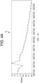
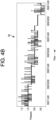
- a line between the three kinds of leakages may sometimes be quite fine, especially the latter two kinds; but to give some idea, one may say that a sudden pressure drop can be quantified by a pressure decrease by more than 0.5 bar in less than 3 hours, a fast pressure drop means that the same pressure decrease can be over the period of 1-2 days, and a slow pressure decrease can be over a period of several weeks.
- These leakages are illustrated on real-life examples in charts 81, 82 and 83 of Figures 4a , 4b and 4c , respectively.
- the heating is maintained by a service company and remotely monitored, it may be important for the maintenance scheduling to get known that the fault (e.g., a leakage) has emerged, what is its extent - the speed of pressure decrease, and to estimate, when the pressure may get below a critical value. This information may be used to improve the economy of the system service and reduce the number of emergency actions by service technicians. Proper notification to the service company may also be important.
- the fault e.g., a leakage
- the present improvement of a pressure monitoring system consists in remote monitoring of heating liquid pressure, processing of received values, modeling of the leakage if it has emerged, estimation of time to reach the critical pressure level, and consistent notification about the system state.
- the goal is to provide information for scheduling a repair action by a service company or issue a warning for the home owner and request a timely refill of the system.
- a signal from a pressure gauge is collected with sufficient frequency either locally or remotely.
- the notification may be immediately issued, which is however not necessarily the subject of the present approach.
- a time series of the pressures is evaluated, typically once a day, e.g., at midnight or before the heating is restarted after a night reduction of heating.
- a daily evaluation may be a sufficient frequency.
- the pressure may vary due to changes of liquid temperature and pump speed during the day. Therefore, an envelope of minimal pressures in the system is searched.
- the day is divided into several intervals, and minima in these intervals may be extracted.
- the daily result or results may be added to the time series of past evaluations.
- Progress of the pressure decrease may be modeled by various functions. Moderate speed of pressure decrease may be approximated by a simple shifted exponential or hyperbolic function of time. Slow pressure decrease may be approximated by a linear function, with a small decrease rate constant. Here, the predicted time of failure may be shorter than in the model noted above. A repair in the case of a slow deterioration of pressure need not necessarily be urgent and thus the main purpose of the present prediction is to issue a warning that the system is not in full health.
- the stored time series of pressure minima is used to fit the model parameters.
- a future predicted course of pressure evolution is computed and the time point, where the curve intersects critical value of the pressure, is issued as a prediction of a critical situation for the latest time of the necessary liquid refill or check for the system.
- the treatment of failure notifications may be determined by two parameters: 1) The predicted time to reaching a critical pressure level, at which the notification is issued; and 2) The duration of regular pressure after the pressure is restored, needed for clearing the previously issued notification.
- the heating system should be equipped with a pressure gauge connected to a suitable device for data transfer.
- a central computing system may receive data from virtually all sites with the present equipment. Every day the present central computing system may evaluate pressures at each site by the above noted approach and store evaluations in a database. If the database for a site contains sufficient number of values, the system may evaluate whether there is a pressure decrease. If the pressure decrease is indicated, one of two models may be created over the data and a curve describing pressure decrease may be constructed. The time, where the curve intersects the value of critical pressure, may be taken as a predicted time of a critical fault. Considering current state of the art of Things, all this functionality may be located on site in a local smart home controller or embedded in the boiler or heat exchanger, and only the result - predicted critical time to failure - may be reported to a central computing system.
- the recipient of this prediction may assign priorities of required repair actions and assemble an economically optimal trip plan for service or repair person.
- the information of probable critical pressure time may be also reported to the home owner or residents via the heating controller.
- time to necessary refill (which may be shorter than time to failure due to some safety time period) may be reported to the owner. Timely refill prevents the system damage before a professional serviceman comes to make a check and repair.
- the system may need to be temporarily worked around or repaired in the meantime such as for a leakage (e.g., the home owner refilling the system), the notification flag may be cleared.
- a leakage e.g., the home owner refilling the system
- An expert may be needed for a permanent repair.
- Some advantages of this approach may incorporate the service of heating systems being optimally planned, the number of emergency service trips being minimized, and heating systems being maintained in time with minimum or no potential damage.
- FIG. 1 is diagram of an example hydronic heating system 30 to which the present approach and system may be applied.
- a pump 31 may be situated on a return line 32, as shown, or situated alternatively on a supply line or pipe 33.
- Return line or pipe 32 may be connected to an input of a boiler 34.
- a heat exchanger, heater or other fluid heating mechanism may be used in lieu of the boiler.
- Supply pipe 33 may be connected to an output of boiler 34.
- a pressure gauge 35 may be attached to supply pipe 33.
- an expansion tank 36 may be connected to supply pipe 33.
- Pipe 33 may go to one or valves, each of which may be connected to a radiator or an underfloor heating or radiative mechanism.
- valves 41, 43, 45 and 47 may be connected to inputs of radiators 42, 44, 46 and 48, respectively.
- the outputs of the radiators may be connected to return pipe 32.
- At an end of return pipe 32 may be an air vent 49 that can be opened to let air out of system 30.
- Air vent 49 may have a valve 73 at its input from pipe or line 32.
- a computer 71 may be connected to pressure gauge 35.
- a temperature sensor 72 may be situated at, on or in supply pipe or line 33 connected to the output of boiler or fluid heater 34. An output of temperature sensor 72 may be connected to computer 71.
- pump 31 and boiler, fluid heater or a heat exchanger 34 may be connected to computer 71. Heat may be provided for system 30 from an external source such as a district heating plant.
- Figure 2 is a flow diagram 50 that reveals the present approach and system that may be used to evaluate heating liquid pressure drops in an example hydronic heating system, such as example system 30 revealed herein.
- the latest pressure data may be obtained, for instance, from a gauge 35 at symbol 51.
- a question of whether a current pressure level is below a pre-determined level may be asked at symbol 52. If an answer is "yes”, then a question of whether a user was notified may be asked at symbol 53. If the user was not notified, then the user should be notified at symbol 54. In other words, this branch may represent a "sudden pressure drop" situation. When the pressure drops below the critical level, the user should be notified immediately and there is no need to execute the calculation.
- a question whether there is an active notification may be asked at symbol 55. If the answer is yes, then a question of whether the timeout has elapsed may be asked at symbol 56. If the answer is yes, then the notification may be cleared at symbol 57. This may represent a situation when the system has recovered from the pressure drop. The pressure may be above a critical level for some time, so that one can clear the notification. One may still want to calculate the slow decrease to potentially detect the trend and create a model of leakage.
- the pressure data may be analyzed and extrapolated. Following symbol 58, a question of whether the pressure in system 30 is expected to reach a pre-determined threshold within a defined interval. If an answer is yes, then a question of whether the user was notified may be asked at symbol 60. If an answer is no, the user may be notified about an upcoming fault at symbol 61.
- a question of whether there is an active notification may be asked at symbol 62. If an answer is yes, then a question of whether a timeout has elapsed may be asked at symbol 63. If an answer is yes, then the notification may be cleared at symbol 64.
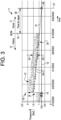
- Figure 3 is a diagram of pressure versus time, depicting a pressure history, in a hydronic heating system particularly at March 15 in graph 11 as noted by vertical line 16.
- a model may be developed from pressure data.
- a time range of the graph may be shown to be from February 15 through March 22.
- the pressure data may be noted in bar units.
- the marks 12 are points of pressure measurements.
- At 0.8 bar is a critical pressure line 13.
- Symbol 14 indicates where the critical pressure was attained.
- Line 15 indicates a region of historical data and line 17 indicates a region of future predicted data.
- At area 18 and moving to the right to a dotted line 19 may indicate where liquid is refilled, pressure is restored, but with the fault not yet repaired.
- Line 21 may be an approximation of a recent gradual pressure drop by a fixed exponential curve.
- Line 22, along with line 23 that is a part of line 21, may indicate variations of pressure in the system. Points 24 may be discarded outliers. Round dots 25 along line 21 may be regarded as minima in intervals. These minima may be taken for an approximation (i.e., a modeling of a leakage). Symbol 26 along line 13 may indicate a predicted critical state. Vertical line 27 indicates a latest time of the next potentially compensatory refill. A time period between the present moment and the predicted critical state or latest time for the next compensatory refill may be regarded as an amount of time available for repair which is indicated by a line 28 that runs between line 16 and line 27.
- a hydronic heating system may incorporate a fluid heating mechanism for a heating system; one or more radiators having a fluid input connected to a fluid output of the fluid heating mechanism, and having a fluid output connected to a fluid input of the fluid heating mechanism; a pump having a fluid connection in series between the fluid heating mechanism and the one or more radiators; a pressure gauge connected at the fluid output of the fluid heating mechanism, and having a signal output indicative of detected pressure at the fluid output of the fluid heating mechanism; and a computer connected to the signal output at the pressure gauge.
- the computer may analyze signals indicative of detected pressures from the pressure gauge.
- the detected pressures that are indicated by the computer may be correlated to conditions of the system.
- the system may further have a temperature sensor at the output of the fluid heating mechanism.
- the temperature sensor may have a signal output indicative of temperature at the output of the fluid heating mechanism, and the signal output may be connected to the computer.
- the fluid heating mechanism and the one or more radiators may contain a fluid under a predetermined pressure.
- a pressure decrease along a series of the detected pressures from old to new may indicate a leakage in the heating system, according to the computer.
- a pressure change of a first predetermined magnitude may be signaled with an automatically issued warning.
- a pressure change of a second predetermined magnitude may indicate a leakage in the heating system, which can be delayed by refilling the heating system.
- the pressure change of a third predetermined magnitude pressure indicative of being below a critical value in the heating system may result in an immediate notification.
- the computer may develop models of pressure loss or leakage from pressures received over time from the pressure gauge.
- the computer may perform one or more actions selected from a group comprising checking heating fluid pressure, processing pressure values, providing leakage models, estimating time to reach a critical pressure, providing notifications of a state of the heating system, issuing warnings, and indicating appropriate times to refill the heating system.
- a time series of pressures may be evaluated at one or more periodical times selected from a group comprising minutely, hourly, daily, and weekly.
- Periodical evaluations of pressures may be added to a time series of past evaluations.
- Pressure changes may be modeled by functions at the computer.
- a first pressure drop may be where a pressure suddenly drops below a critical level.
- a second pressure drop may be where the pressure drops fast two or less days to drop below a critical level and more slowly than the first pressure drop.
- a third pressure drop may be where the pressure drops more slowly than the second pressure drop.
- a stored time series of pressure minima may be used to fit model parameters; a future predicted course of a curve to reveal a pressure evolution may be computed and a time point where the curve intersects a critical value of the curve of the pressure evolution may be issued as a prediction of a critical situation for a latest time of a necessary fluid refill or a check of the heating system; and/or a failure notification may be determined by a predicted time to a critical pressure level at which the failure notification is issued, and then a predetermined duration of regular pressure after the pressure drop is restored may be needed for clearing the failure notification.
- the computer may evaluate pressures at each site of multiple subsystems of the heating system and store evaluations in a database corresponding to the pressures, respectively.
- the computer may determine if there is a pressure decrease. If the pressure decrease is indicated, then a model may be created over the data and a curve describing the pressure decrease may be constructed, and the time, where the curve intersects a value of a critical pressure, may be a predicted time of a critical fault.
- the predicted time of the critical fault provided to a recipient may cause the recipient to repair the heating system within the predicted time and thus result in a clearing of a failure notification flag before harm affects the heating system.
- An approach for monitoring hydronic heating system may incorporate pumping fluid through a circulatory subsystem of a hydronic heating system, heating the fluid in the circulatory subsystem, recording pressure data over time with a computer from a pressure sensor coupled to the circulatory subsystem, and performing an analysis of the pressure data to determine health of the circulatory subsystem.
- the circulatory subsystem may incorporate one or more heating radiators; a fluid heating mechanism having an output connected to an input of the one or more heating radiators, and having an input connected to an output of the one or more heating radiators; and a pump connected between the radiators and the fluid heating mechanism.
- the analysis of the pressure data may reveal a pressure change of a first predetermined magnitude that results in a signal from the computer providing an automatically issued warning; a pressure change of a second predetermined magnitude that results in a signal from the computer providing an indication of a leakage in the circulatory subsystem, which can be delayed by refilling the system; and a pressure change of a third predetermined magnitude that results in a signal from the computer providing an indication of pressure in the circulatory system being below a critical value and thus resulting in an immediate notification.
- a pressure monitoring device for a hydronic heating system may incorporate a radiator assembly, a heater connected to the radiator assembly, a pump connected to the heater and the radiator assembly, a pressure gauge connected to the radiator assembly, and a pressure analyzer connected to the pressure gauge.
- the pressure analyzer may record pressures detected by the pressure gauge over time, and deduce conditions of the hydronic heating system from the pressures recorded over time.
- the fluid may be a liquid.
- the radiator assembly may be situated anywhere in, below, above or proximate to a space to be heated.
Landscapes
- Engineering & Computer Science (AREA)
- Physics & Mathematics (AREA)
- Thermal Sciences (AREA)
- Chemical & Material Sciences (AREA)
- Combustion & Propulsion (AREA)
- Mechanical Engineering (AREA)
- General Engineering & Computer Science (AREA)
- General Physics & Mathematics (AREA)
- Steam Or Hot-Water Central Heating Systems (AREA)
Claims (5)
- Ein hydronisches Heizungssystem (30), das Folgendes beinhaltet:einen Fluidheizungsmechanismus (34);einen oder mehrere Heizkörper (42, 44, 46, 48), die einen Fluideingang aufweisen, der mit einem Fluidausgang des Fluidheizungsmechanismus (34) verbunden ist, und einen Fluidausgang aufweisen, der mit einem Fluideingang des Fluidheizungsmechanismus (34) verbunden ist;eine Pumpe (31), die eine Fluidverbindung in Reihe zwischen dem Fluidheizungsmechanismus (34) und dem einen oder den mehreren Heizkörpern (42, 44, 46, 48) aufweist, wobei die Pumpe (31) dazu konfiguriert ist, ein Heizfluid umzuwälzen; undein Druckmessgerät (35), das an dem Fluidausgang des Fluidheizungsmechanismus (34) angeschlossen ist und dazu konfiguriert ist, Drucksignale auszugeben, die erfasste Drücke des Heizfluids an dem Fluidausgang des Fluidheizungsmechanismus (34) angeben;dadurch gekennzeichnet, dass das hydronische Heizungssystem (30) ferner einen Computer (71) beinhaltet, der dazu konfiguriert ist:die Drucksignale zu empfangen;eine Zeitfolge von Druckminima basierend auf den Drucksignalen zu speichern;basierend auf den Druckminima Parameter eines Modells zu bestimmen, wobei ein Tag in mehrere Intervalle unterteilt ist und Minima in diesen Intervallen ausgezogen werden;eine Zeit zu bestimmen, zu der das zukünftige vorhergesagte Druckdaten angebende Modell einen kritischen Wert schneidet; undbasierend auf einer vorhergesagten Zeit, bis die zukünftigen vorhergesagten Druckdaten den kritischen Wert schneiden, als Reaktion auf einen Druckabfall eine Störungsmeldung zu erzeugen.
- System gemäß Anspruch 1, ferner beinhaltend einen Temperatursensor (72) an dem Ausgang des Fluidheizungsmechanismus (34), wobei der Temperatursensor (72) dazu konfiguriert ist, ein Temperatursignal an den Computer (71) auszugeben, das eine Temperatur an dem Ausgang des Fluidheizungsmechanismus (34) angibt.
- System gemäß einem der vorhergehenden Ansprüche, wobei in einem kalten Zustand der Fluidheizungsmechanismus (34) und der eine oder die mehreren Heizkörper (42, 44, 46, 48) das Heizfluid unter einem vorgegebenen Druck enthalten.
- System gemäß Anspruch 1, wobei der Computer (71) dazu konfiguriert ist, als Reaktion auf eine Reparatur des Heizungssystems innerhalb der vorhergesagten Zeit, die Störungsmeldung zu löschen.
- Ein Verfahren zum Überwachen des hydronischen Heizungssystems (30) gemäß einem der vorhergehenden Ansprüche, das Folgendes beinhaltet:Pumpen, durch die Pumpe (31), des Heizfluids durch ein Kreislaufteilsystem des hydronischen Heizungssystems (30);Erhitzen, durch den Fluidheizungsmechanismus (34), des Heizfluids in dem Kreislaufteilsystem;dadurch gekennzeichnet, dass das Verfahren ferner Folgendes beinhaltet:Aufzeichnen, durch den Computer (71), einer Zeitfolge von Druckminima, die von dem an das Kreislaufteilsystem gekoppelten Druckmessgerät (35) her empfangen werden;Bestimmen, durch den Computer (71), von Modellparametern basierend auf den Druckminima, wobei ein Tag in mehrere Intervalle unterteilt ist und Minima in diesen Intervallen ausgezogen werden, Bestimmen, durch den Computer (71), der Zeit, zu der ein zukünftige vorhergesagte Druckdaten angebendes Modell den kritischen Wert schneidet;Erzeugen, durch den Computer (71), der Störungsmeldung als Reaktion auf den Druckabfall basierend auf der vorhergesagten Zeit bis zu dem kritischen Wert.
Applications Claiming Priority (2)
| Application Number | Priority Date | Filing Date | Title |
|---|---|---|---|
| US15/445,849 US10401039B2 (en) | 2017-02-28 | 2017-02-28 | Evaluation of heating liquid pressure drops in a hydronic heating system |
| PCT/US2018/020072 WO2018160609A1 (en) | 2017-02-28 | 2018-02-28 | Evaluation of heating liquid pressure drops in a hydronic heating system |
Publications (2)
| Publication Number | Publication Date |
|---|---|
| EP3589930A1 EP3589930A1 (de) | 2020-01-08 |
| EP3589930B1 true EP3589930B1 (de) | 2024-10-09 |
Family
ID=61656358
Family Applications (1)
| Application Number | Title | Priority Date | Filing Date |
|---|---|---|---|
| EP18711454.1A Active EP3589930B1 (de) | 2017-02-28 | 2018-02-28 | Auswertung von heizflüssigkeitsdruckabfällen in einem hydronischen heizsystem |
Country Status (3)
| Country | Link |
|---|---|
| US (1) | US10401039B2 (de) |
| EP (1) | EP3589930B1 (de) |
| WO (1) | WO2018160609A1 (de) |
Families Citing this family (15)
| Publication number | Priority date | Publication date | Assignee | Title |
|---|---|---|---|---|
| WO2017027857A1 (en) | 2015-08-12 | 2017-02-16 | Sarkis Sr Anthony Michael | Hot water heating system and related methods |
| US10677674B2 (en) * | 2016-12-15 | 2020-06-09 | Lee Hiram Stevens | Device and methodology for early detection of fluid loss and notification and system shutdown for a closed loop fluid heat transfer system |
| US12000600B2 (en) * | 2018-05-04 | 2024-06-04 | Hydronics, Llc | Device and methodology for early detection of fluid loss and notification and system shutdown for a closed loop fluid heat transfer system |
| US11531310B2 (en) | 2018-06-15 | 2022-12-20 | Johnson Controls Tyco IP Holdings LLP | Adaptive selection of machine learning/deep learning model with optimal hyper-parameters for anomaly detection of connected chillers |
| US11859846B2 (en) * | 2018-06-15 | 2024-01-02 | Johnson Controls Tyco IP Holdings LLP | Cost savings from fault prediction and diagnosis |
| JP7094186B2 (ja) * | 2018-09-14 | 2022-07-01 | 東京瓦斯株式会社 | 熱交換制御装置 |
| US11898761B2 (en) * | 2020-03-04 | 2024-02-13 | Harvest Thermal, Inc. | Control systems and methods for managing rate of heat delivery in hydronic systems |
| GB2596340B (en) * | 2020-06-26 | 2023-02-08 | Ghrian Ltd | Apparatus and method |
| WO2022168026A1 (en) * | 2021-02-07 | 2022-08-11 | Octopus Energy Group Limited | Energy storage arrangement and installations |
| GB202101678D0 (en) | 2021-02-07 | 2021-03-24 | Octopus Energy Ltd | Methods and systems and apparatus to support reduced energy and water usage |
| CN113007784B (zh) * | 2021-04-25 | 2022-06-28 | 西安热工研究院有限公司 | 一种大型供热管网综合评价方法 |
| DE102021111467A1 (de) * | 2021-05-04 | 2022-11-10 | Vaillant Gmbh | Verfahren zur Überwachung einer Heizungsanlage, Computerprogramm, Regel- und Steuergerät, Heizungsanlage und Verwendung von Betriebsdaten einer Heizungsanlage |
| US12504751B2 (en) | 2022-01-19 | 2025-12-23 | Transportation Ip Holdings, Llc | Inspection system and method |
| GB2606621B (en) * | 2022-03-10 | 2023-06-21 | Intelligent Valves Ltd | Smart heating system and associated method |
| IT202300024597A1 (it) * | 2023-11-21 | 2025-05-21 | Ariston Spa | Metodo di controllo della pressione del fluido termovettore in un impianto di riscaldamento |
Family Cites Families (56)
| Publication number | Priority date | Publication date | Assignee | Title |
|---|---|---|---|---|
| SE460430B (sv) | 1987-07-29 | 1989-10-09 | Watector Ab | Anordning foer att foerhindra vattenskador i byggnader |
| JP3759557B2 (ja) * | 1998-05-29 | 2006-03-29 | 三洋電機株式会社 | 空気調和装置の遠隔監視システム |
| CN1182700C (zh) | 1999-04-30 | 2004-12-29 | 汤姆森特许公司 | 适用于双向通信设备的状态监控和数据处理系统 |
| US6785724B1 (en) | 1999-11-02 | 2004-08-31 | Walchem Corporation | On-demand web server |
| JP4141084B2 (ja) * | 2000-05-01 | 2008-08-27 | 三洋電機株式会社 | 蓄熱式空気調和システム及びその運転方法 |
| US20030093186A1 (en) * | 2001-11-15 | 2003-05-15 | Patterson Wade C. | System and method for controlling temperature of a liquid residing within a tank |
| DE10312667A1 (de) | 2003-03-21 | 2004-10-07 | Honeywell B.V. | Verfahren zum Überwachen eines Boilersystems für Wasser und Vorrichtung zur Durchführung des Verfahrens |
| GB0320696D0 (en) | 2003-09-04 | 2003-10-01 | Pickering Robert | Auto filling system & leak detector |
| US7010925B2 (en) * | 2004-06-07 | 2006-03-14 | Carrier Corporation | Method of controlling a carbon dioxide heat pump water heating system |
| US7296426B2 (en) * | 2005-02-23 | 2007-11-20 | Emerson Electric Co. | Interactive control system for an HVAC system |
| CN101218790A (zh) | 2005-07-04 | 2008-07-09 | Sk电信股份有限公司 | 家庭网络系统及其控制方法、设置家庭网络系统的住宅网关的方法以及处理家庭网络系统的事件协议的方法 |
| CA2793796C (en) * | 2006-04-18 | 2016-07-05 | Oy Halton Group, Ltd. | Modular wall unit with mini exhaust hood |
| US9863646B2 (en) * | 2007-01-26 | 2018-01-09 | David E. Johnson, Jr. | Modulation control of hydronic systems |
| DE102007010803B4 (de) | 2007-03-02 | 2009-06-04 | Viessmann Werke Gmbh & Co Kg | Vorrichtung und Verfahren zum Steuern und Überwachen von Haustechnikeinrichtungen |
| US7966152B2 (en) | 2008-04-23 | 2011-06-21 | Honeywell International Inc. | System, method and algorithm for data-driven equipment performance monitoring |
| US10168073B2 (en) * | 2008-07-01 | 2019-01-01 | Carina Technology, Inc. | Water heater demand side management system |
| US8204717B2 (en) | 2009-04-01 | 2012-06-19 | Honeywell International Inc. | Cloud computing as a basis for equipment health monitoring service |
| US20110135289A1 (en) * | 2009-12-08 | 2011-06-09 | Kayser Kenneth W | Water heating system with point-of-use control |
| DE102009060469A1 (de) | 2009-12-22 | 2011-06-30 | eQ-3 AG, 26789 | Verfahren und Vorrichtung zur Sicherung der Kommunikation zwischen einem Heimautomatisierungsserver und einem zentralen Konfigurationsserver |
| US8572241B2 (en) | 2010-09-17 | 2013-10-29 | Microsoft Corporation | Integrating external and cluster heat map data |
| US9009001B2 (en) | 2011-05-26 | 2015-04-14 | Honeywell International Inc. | Monitoring for invalid data from field instruments |
| US8805000B2 (en) | 2011-08-23 | 2014-08-12 | Honeywell International Inc. | Mobile energy audit system and method |
| CA2792823C (en) * | 2011-10-21 | 2019-10-15 | Cleaver-Brooks, Inc. | System and method of controlling condensing and non-condensing boiler firing rates |
| DE102011118565A1 (de) | 2011-11-15 | 2013-05-16 | Giesecke & Devrient Gmbh | Smart Home-Gerät, Smart Home-Steuereinheit, Smart Home-System und Verfahren zur Einbindung eines Smart Home-Geräts in ein Smart Home-System |
| US10088853B2 (en) | 2012-05-02 | 2018-10-02 | Honeywell International Inc. | Devices and methods for interacting with an HVAC controller |
| US9256846B2 (en) | 2012-05-16 | 2016-02-09 | Honeywell International Inc. | System and method for performance monitoring of a population of equipment |
| US8659302B1 (en) * | 2012-09-21 | 2014-02-25 | Nest Labs, Inc. | Monitoring and recoverable protection of thermostat switching circuitry |
| US9551504B2 (en) * | 2013-03-15 | 2017-01-24 | Emerson Electric Co. | HVAC system remote monitoring and diagnosis |
| US9507353B2 (en) | 2013-08-06 | 2016-11-29 | Asoka Usa Corporation | PLC based thermostat temperature control for heating systems |
| KR101526149B1 (ko) | 2013-10-17 | 2015-06-09 | 주식회사 경동나비엔 | 표준프로토콜기반의 보일러 및 온수기 캐스케이드 통합원격관리 시스템 및 그 방법 |
| US9995501B2 (en) | 2013-11-04 | 2018-06-12 | Honeywell International Inc. | Remote contractor system with data analytics for identifying site specific operational abnormalities |
| GB201319645D0 (en) * | 2013-11-07 | 2013-12-25 | Sentinel Performance Solutions Ltd | Monitoring and operation of a liquid flow circuit containing a chemical additive |
| US20150167989A1 (en) * | 2013-12-18 | 2015-06-18 | Google Inc. | Intelligent environment control including use of smart meter and energy cost information in heat pump and auxiliary heating control |
| US9532131B2 (en) | 2014-02-21 | 2016-12-27 | Apple Inc. | System and method of improving voice quality in a wireless headset with untethered earbuds of a mobile device |
| LT2921926T (lt) | 2014-03-16 | 2017-02-10 | Opti Automation Oy | Valdymo sistema ir būdas |
| US9791839B2 (en) * | 2014-03-28 | 2017-10-17 | Google Inc. | User-relocatable self-learning environmental control device capable of adapting previous learnings to current location in controlled environment |
| US9568201B2 (en) * | 2014-03-28 | 2017-02-14 | Google Inc. | Environmental control system retrofittable with multiple types of boiler-based heating systems |
| KR101485829B1 (ko) | 2014-04-28 | 2015-01-29 | 가온미디어 주식회사 | 듀얼 클라우드 기반의 어시스트 게이트웨이를 이용한 홈 씬클라이언트 댁내정보 수집처리 시스템 및 그 운영 방법, 그리고 이를 위한 컴퓨터로 판독가능한 기록매체 |
| US9551495B2 (en) * | 2014-05-07 | 2017-01-24 | Emerson Electric Co. | HVAC system grading systems and methods |
| GB201409495D0 (en) | 2014-05-28 | 2014-07-09 | Oe Innovation Ltd | Smart switches |
| US10126009B2 (en) | 2014-06-20 | 2018-11-13 | Honeywell International Inc. | HVAC zoning devices, systems, and methods |
| CN105467932A (zh) | 2014-08-11 | 2016-04-06 | 中兴通讯股份有限公司 | 一种终端系统发热优化的方法及装置 |
| WO2016038374A1 (en) | 2014-09-11 | 2016-03-17 | Alertme.Com Ltd | System for connecting and controlling multiple devices |
| GB2530086A (en) | 2014-09-12 | 2016-03-16 | Michael John Bradley | System and method for remotely optimising control algorithms and rulesets on a network server or using cloud based services |
| CN104330973B (zh) | 2014-09-23 | 2017-02-15 | 小米科技有限责任公司 | 设备控制方法和装置 |
| CN104360607A (zh) | 2014-10-23 | 2015-02-18 | 杭州赫智电子科技有限公司 | 一种智能电器系统及智能电器控制方法 |
| CN104407592B (zh) | 2014-11-27 | 2018-11-23 | 小米科技有限责任公司 | 一种调整智能家居设备运行状态的方法及装置 |
| US10379512B2 (en) | 2014-12-05 | 2019-08-13 | Honeywell International Inc. | Monitoring and control system using cloud services |
| WO2016093676A2 (ko) | 2014-12-12 | 2016-06-16 | 주식회사 경동원 | 무선통신을 이용한 홈네트워크 시스템 및 이를 이용한 알람방법과 제어방법 |
| CN104459306B (zh) | 2014-12-18 | 2017-02-22 | 东北大学 | 一种电熔镁群炉用电需量远程监控系统及方法 |
| US10372093B2 (en) | 2015-02-26 | 2019-08-06 | Ademco Inc. | Comfort mapping using wearables |
| US10544956B2 (en) * | 2015-06-08 | 2020-01-28 | Carrier Corporation | HVAC system start/stop control |
| CN205119225U (zh) | 2015-10-26 | 2016-03-30 | 北京北方智能科技有限公司 | 一种家用采暖系统远程监控系统 |
| US9939162B2 (en) * | 2015-11-13 | 2018-04-10 | Honeywell International Inc. | HVAC boiler controller |
| CN105721501A (zh) | 2016-04-09 | 2016-06-29 | 杭州迈欧科技有限公司 | 锅炉物联网监控系统 |
| US10000912B2 (en) * | 2016-06-15 | 2018-06-19 | Honeywell International Inc. | Freeze prediction system |
-
2017
- 2017-02-28 US US15/445,849 patent/US10401039B2/en active Active
-
2018
- 2018-02-28 WO PCT/US2018/020072 patent/WO2018160609A1/en not_active Ceased
- 2018-02-28 EP EP18711454.1A patent/EP3589930B1/de active Active
Also Published As
| Publication number | Publication date |
|---|---|
| US10401039B2 (en) | 2019-09-03 |
| WO2018160609A1 (en) | 2018-09-07 |
| US20180245801A1 (en) | 2018-08-30 |
| EP3589930A1 (de) | 2020-01-08 |
Similar Documents
| Publication | Publication Date | Title |
|---|---|---|
| EP3589930B1 (de) | Auswertung von heizflüssigkeitsdruckabfällen in einem hydronischen heizsystem | |
| US20130173178A1 (en) | Apparatus and Method for Monitoring a Steam Plant | |
| US10000912B2 (en) | Freeze prediction system | |
| EP2866117B1 (de) | Verteiltes adaptives und prädiktives Heizungssteuersystem und entsprechendes Verfahren | |
| US20030216888A1 (en) | Predictive maintenance display system | |
| RU2654807C2 (ru) | Способ контроля клапана авиационного двигателя | |
| CN113266972A (zh) | 用于制冷系统的维护和诊断 | |
| CN108071427B (zh) | 用于对发动机执行基于状况的维护的系统和方法 | |
| EP3584656B1 (de) | Risikobewertungsvorrichtung, risikobewertungsverfahren und risikobewertungsprogramm | |
| KR102121787B1 (ko) | 원격검침 데이터를 이용한 적산열량계와 사용자 설비 장애 검출 시스템 | |
| JP7175752B2 (ja) | 機械設備の診断方法及び機械設備の診断装置 | |
| Schein et al. | Application of control charts for detecting faults in variable-air-volume boxes | |
| US20240280272A1 (en) | Device and methodology for early detection of fluid loss and notification and system shutdown for a closed loop fluid heat transfer system | |
| US10676206B2 (en) | System and method for heat exchanger failure detection | |
| WO2022185110A1 (en) | Method and control system of a fluid system | |
| GB2611100A (en) | Determination of boiler circulation faults | |
| JP2018205992A (ja) | 機器診断システム | |
| WO2017212226A1 (en) | Automatic heating-system filling apparatus, a method of improving the safety of a heating system, a method of automatically testing and a method of managing an automatically replenishing heating system | |
| KR20180006094A (ko) | 상수관망에서 회귀분석을 통한 최적 운전모드 제시방법 | |
| KR100890528B1 (ko) | 펌프장 침수 예상 경보시스템 | |
| US9507344B2 (en) | Index generation and embedded fusion for controller performance monitoring | |
| US20230193809A1 (en) | Cooling system and method | |
| JP7644035B2 (ja) | 管理システムおよび管理方法 | |
| WO2020115554A1 (en) | Devices and method for electric heating trace system management | |
| CN109297733B (zh) | 换热器诊断方法 |
Legal Events
| Date | Code | Title | Description |
|---|---|---|---|
| STAA | Information on the status of an ep patent application or granted ep patent |
Free format text: STATUS: UNKNOWN |
|
| STAA | Information on the status of an ep patent application or granted ep patent |
Free format text: STATUS: THE INTERNATIONAL PUBLICATION HAS BEEN MADE |
|
| PUAI | Public reference made under article 153(3) epc to a published international application that has entered the european phase |
Free format text: ORIGINAL CODE: 0009012 |
|
| STAA | Information on the status of an ep patent application or granted ep patent |
Free format text: STATUS: REQUEST FOR EXAMINATION WAS MADE |
|
| 17P | Request for examination filed |
Effective date: 20190926 |
|
| AK | Designated contracting states |
Kind code of ref document: A1 Designated state(s): AL AT BE BG CH CY CZ DE DK EE ES FI FR GB GR HR HU IE IS IT LI LT LU LV MC MK MT NL NO PL PT RO RS SE SI SK SM TR |
|
| AX | Request for extension of the european patent |
Extension state: BA ME |
|
| DAV | Request for validation of the european patent (deleted) | ||
| DAX | Request for extension of the european patent (deleted) | ||
| RAP1 | Party data changed (applicant data changed or rights of an application transferred) |
Owner name: ADEMCO INC. |
|
| STAA | Information on the status of an ep patent application or granted ep patent |
Free format text: STATUS: EXAMINATION IS IN PROGRESS |
|
| 17Q | First examination report despatched |
Effective date: 20220202 |
|
| P01 | Opt-out of the competence of the unified patent court (upc) registered |
Effective date: 20230601 |
|
| GRAP | Despatch of communication of intention to grant a patent |
Free format text: ORIGINAL CODE: EPIDOSNIGR1 |
|
| STAA | Information on the status of an ep patent application or granted ep patent |
Free format text: STATUS: GRANT OF PATENT IS INTENDED |
|
| RIC1 | Information provided on ipc code assigned before grant |
Ipc: F24H 15/12 20220101ALI20240415BHEP Ipc: F24D 19/10 20060101ALI20240415BHEP Ipc: F24D 19/02 20060101ALI20240415BHEP Ipc: F24D 3/02 20060101ALI20240415BHEP Ipc: G01M 3/28 20060101ALI20240415BHEP Ipc: G01M 3/32 20060101AFI20240415BHEP |
|
| INTG | Intention to grant announced |
Effective date: 20240506 |
|
| GRAS | Grant fee paid |
Free format text: ORIGINAL CODE: EPIDOSNIGR3 |
|
| GRAA | (expected) grant |
Free format text: ORIGINAL CODE: 0009210 |
|
| STAA | Information on the status of an ep patent application or granted ep patent |
Free format text: STATUS: THE PATENT HAS BEEN GRANTED |
|
| RIN1 | Information on inventor provided before grant (corrected) |
Inventor name: MAREK, SIKORA Inventor name: SCHINDLER, ZDENEK |
|
| AK | Designated contracting states |
Kind code of ref document: B1 Designated state(s): AL AT BE BG CH CY CZ DE DK EE ES FI FR GB GR HR HU IE IS IT LI LT LU LV MC MK MT NL NO PL PT RO RS SE SI SK SM TR |
|
| REG | Reference to a national code |
Ref country code: CH Ref legal event code: EP |
|
| REG | Reference to a national code |
Ref country code: DE Ref legal event code: R096 Ref document number: 602018075152 Country of ref document: DE |
|
| REG | Reference to a national code |
Ref country code: IE Ref legal event code: FG4D |
|
| REG | Reference to a national code |
Ref country code: NL Ref legal event code: FP |
|
| REG | Reference to a national code |
Ref country code: LT Ref legal event code: MG9D |
|
| REG | Reference to a national code |
Ref country code: AT Ref legal event code: MK05 Ref document number: 1731046 Country of ref document: AT Kind code of ref document: T Effective date: 20241009 |
|
| PG25 | Lapsed in a contracting state [announced via postgrant information from national office to epo] |
Ref country code: HR Free format text: LAPSE BECAUSE OF FAILURE TO SUBMIT A TRANSLATION OF THE DESCRIPTION OR TO PAY THE FEE WITHIN THE PRESCRIBED TIME-LIMIT Effective date: 20241009 Ref country code: PT Free format text: LAPSE BECAUSE OF FAILURE TO SUBMIT A TRANSLATION OF THE DESCRIPTION OR TO PAY THE FEE WITHIN THE PRESCRIBED TIME-LIMIT Effective date: 20250210 Ref country code: IS Free format text: LAPSE BECAUSE OF FAILURE TO SUBMIT A TRANSLATION OF THE DESCRIPTION OR TO PAY THE FEE WITHIN THE PRESCRIBED TIME-LIMIT Effective date: 20250209 |
|
| PG25 | Lapsed in a contracting state [announced via postgrant information from national office to epo] |
Ref country code: FI Free format text: LAPSE BECAUSE OF FAILURE TO SUBMIT A TRANSLATION OF THE DESCRIPTION OR TO PAY THE FEE WITHIN THE PRESCRIBED TIME-LIMIT Effective date: 20241009 |
|
| PG25 | Lapsed in a contracting state [announced via postgrant information from national office to epo] |
Ref country code: BG Free format text: LAPSE BECAUSE OF FAILURE TO SUBMIT A TRANSLATION OF THE DESCRIPTION OR TO PAY THE FEE WITHIN THE PRESCRIBED TIME-LIMIT Effective date: 20241009 |
|
| PG25 | Lapsed in a contracting state [announced via postgrant information from national office to epo] |
Ref country code: ES Free format text: LAPSE BECAUSE OF FAILURE TO SUBMIT A TRANSLATION OF THE DESCRIPTION OR TO PAY THE FEE WITHIN THE PRESCRIBED TIME-LIMIT Effective date: 20241009 |
|
| PG25 | Lapsed in a contracting state [announced via postgrant information from national office to epo] |
Ref country code: NO Free format text: LAPSE BECAUSE OF FAILURE TO SUBMIT A TRANSLATION OF THE DESCRIPTION OR TO PAY THE FEE WITHIN THE PRESCRIBED TIME-LIMIT Effective date: 20250109 |
|
| PG25 | Lapsed in a contracting state [announced via postgrant information from national office to epo] |
Ref country code: LV Free format text: LAPSE BECAUSE OF FAILURE TO SUBMIT A TRANSLATION OF THE DESCRIPTION OR TO PAY THE FEE WITHIN THE PRESCRIBED TIME-LIMIT Effective date: 20241009 Ref country code: GR Free format text: LAPSE BECAUSE OF FAILURE TO SUBMIT A TRANSLATION OF THE DESCRIPTION OR TO PAY THE FEE WITHIN THE PRESCRIBED TIME-LIMIT Effective date: 20250110 Ref country code: AT Free format text: LAPSE BECAUSE OF FAILURE TO SUBMIT A TRANSLATION OF THE DESCRIPTION OR TO PAY THE FEE WITHIN THE PRESCRIBED TIME-LIMIT Effective date: 20241009 |
|
| PG25 | Lapsed in a contracting state [announced via postgrant information from national office to epo] |
Ref country code: PL Free format text: LAPSE BECAUSE OF FAILURE TO SUBMIT A TRANSLATION OF THE DESCRIPTION OR TO PAY THE FEE WITHIN THE PRESCRIBED TIME-LIMIT Effective date: 20241009 |
|
| PG25 | Lapsed in a contracting state [announced via postgrant information from national office to epo] |
Ref country code: RS Free format text: LAPSE BECAUSE OF FAILURE TO SUBMIT A TRANSLATION OF THE DESCRIPTION OR TO PAY THE FEE WITHIN THE PRESCRIBED TIME-LIMIT Effective date: 20250109 |
|
| PG25 | Lapsed in a contracting state [announced via postgrant information from national office to epo] |
Ref country code: SM Free format text: LAPSE BECAUSE OF FAILURE TO SUBMIT A TRANSLATION OF THE DESCRIPTION OR TO PAY THE FEE WITHIN THE PRESCRIBED TIME-LIMIT Effective date: 20241009 |
|
| REG | Reference to a national code |
Ref country code: NL Ref legal event code: PD Owner name: RESIDEO LLC; US Free format text: DETAILS ASSIGNMENT: CHANGE OF OWNER(S), CHANGE OF LEGAL ENTITY; FORMER OWNER NAME: RESIDEO LLC Effective date: 20250703 |
|
| PG25 | Lapsed in a contracting state [announced via postgrant information from national office to epo] |
Ref country code: DK Free format text: LAPSE BECAUSE OF FAILURE TO SUBMIT A TRANSLATION OF THE DESCRIPTION OR TO PAY THE FEE WITHIN THE PRESCRIBED TIME-LIMIT Effective date: 20241009 |
|
| REG | Reference to a national code |
Ref country code: DE Ref legal event code: R097 Ref document number: 602018075152 Country of ref document: DE |
|
| PG25 | Lapsed in a contracting state [announced via postgrant information from national office to epo] |
Ref country code: EE Free format text: LAPSE BECAUSE OF FAILURE TO SUBMIT A TRANSLATION OF THE DESCRIPTION OR TO PAY THE FEE WITHIN THE PRESCRIBED TIME-LIMIT Effective date: 20241009 |
|
| PG25 | Lapsed in a contracting state [announced via postgrant information from national office to epo] |
Ref country code: RO Free format text: LAPSE BECAUSE OF FAILURE TO SUBMIT A TRANSLATION OF THE DESCRIPTION OR TO PAY THE FEE WITHIN THE PRESCRIBED TIME-LIMIT Effective date: 20241009 |
|
| PG25 | Lapsed in a contracting state [announced via postgrant information from national office to epo] |
Ref country code: SK Free format text: LAPSE BECAUSE OF FAILURE TO SUBMIT A TRANSLATION OF THE DESCRIPTION OR TO PAY THE FEE WITHIN THE PRESCRIBED TIME-LIMIT Effective date: 20241009 |
|
| PG25 | Lapsed in a contracting state [announced via postgrant information from national office to epo] |
Ref country code: CZ Free format text: LAPSE BECAUSE OF FAILURE TO SUBMIT A TRANSLATION OF THE DESCRIPTION OR TO PAY THE FEE WITHIN THE PRESCRIBED TIME-LIMIT Effective date: 20241009 |
|
| PG25 | Lapsed in a contracting state [announced via postgrant information from national office to epo] |
Ref country code: IT Free format text: LAPSE BECAUSE OF FAILURE TO SUBMIT A TRANSLATION OF THE DESCRIPTION OR TO PAY THE FEE WITHIN THE PRESCRIBED TIME-LIMIT Effective date: 20241009 |
|
| PLBE | No opposition filed within time limit |
Free format text: ORIGINAL CODE: 0009261 |
|
| STAA | Information on the status of an ep patent application or granted ep patent |
Free format text: STATUS: NO OPPOSITION FILED WITHIN TIME LIMIT |
|
| REG | Reference to a national code |
Ref country code: DE Ref legal event code: R119 Ref document number: 602018075152 Country of ref document: DE |
|
| PG25 | Lapsed in a contracting state [announced via postgrant information from national office to epo] |
Ref country code: SE Free format text: LAPSE BECAUSE OF FAILURE TO SUBMIT A TRANSLATION OF THE DESCRIPTION OR TO PAY THE FEE WITHIN THE PRESCRIBED TIME-LIMIT Effective date: 20241009 |
|
| PG25 | Lapsed in a contracting state [announced via postgrant information from national office to epo] |
Ref country code: MC Free format text: LAPSE BECAUSE OF FAILURE TO SUBMIT A TRANSLATION OF THE DESCRIPTION OR TO PAY THE FEE WITHIN THE PRESCRIBED TIME-LIMIT Effective date: 20241009 |
|
| 26N | No opposition filed |
Effective date: 20250710 |
|
| REG | Reference to a national code |
Ref country code: CH Ref legal event code: PL |
|
| PG25 | Lapsed in a contracting state [announced via postgrant information from national office to epo] |
Ref country code: LU Free format text: LAPSE BECAUSE OF NON-PAYMENT OF DUE FEES Effective date: 20250228 |
|
| PG25 | Lapsed in a contracting state [announced via postgrant information from national office to epo] |
Ref country code: CH Free format text: LAPSE BECAUSE OF NON-PAYMENT OF DUE FEES Effective date: 20250228 |
|
| REG | Reference to a national code |
Ref country code: BE Ref legal event code: MM Effective date: 20250228 |
|
| PG25 | Lapsed in a contracting state [announced via postgrant information from national office to epo] |
Ref country code: DE Free format text: LAPSE BECAUSE OF NON-PAYMENT OF DUE FEES Effective date: 20250902 |
|
| PG25 | Lapsed in a contracting state [announced via postgrant information from national office to epo] |
Ref country code: FR Free format text: LAPSE BECAUSE OF NON-PAYMENT OF DUE FEES Effective date: 20250228 |
|
| PG25 | Lapsed in a contracting state [announced via postgrant information from national office to epo] |
Ref country code: BE Free format text: LAPSE BECAUSE OF NON-PAYMENT OF DUE FEES Effective date: 20250228 |
|
| PG25 | Lapsed in a contracting state [announced via postgrant information from national office to epo] |
Ref country code: IE Free format text: LAPSE BECAUSE OF NON-PAYMENT OF DUE FEES Effective date: 20250228 |
|
| PGFP | Annual fee paid to national office [announced via postgrant information from national office to epo] |
Ref country code: NL Payment date: 20260220 Year of fee payment: 9 |
|
| PGFP | Annual fee paid to national office [announced via postgrant information from national office to epo] |
Ref country code: GB Payment date: 20260223 Year of fee payment: 9 |