EP3589925B1 - Bildbasiertes handhaltbares bildgebersystem - Google Patents
Bildbasiertes handhaltbares bildgebersystem Download PDFInfo
- Publication number
- EP3589925B1 EP3589925B1 EP18761717.0A EP18761717A EP3589925B1 EP 3589925 B1 EP3589925 B1 EP 3589925B1 EP 18761717 A EP18761717 A EP 18761717A EP 3589925 B1 EP3589925 B1 EP 3589925B1
- Authority
- EP
- European Patent Office
- Prior art keywords
- signal
- image
- spectrometer
- sensor
- tilt angle
- Prior art date
- Legal status (The legal status is an assumption and is not a legal conclusion. Google has not performed a legal analysis and makes no representation as to the accuracy of the status listed.)
- Active
Links
Images


Classifications
-
- G—PHYSICS
- G01—MEASURING; TESTING
- G01B—MEASURING LENGTH, THICKNESS OR SIMILAR LINEAR DIMENSIONS; MEASURING ANGLES; MEASURING AREAS; MEASURING IRREGULARITIES OF SURFACES OR CONTOURS
- G01B9/00—Measuring instruments characterised by the use of optical techniques
- G01B9/02—Interferometers
- G01B9/0209—Low-coherence interferometers
- G01B9/02091—Tomographic interferometers, e.g. based on optical coherence
-
- G—PHYSICS
- G01—MEASURING; TESTING
- G01J—MEASUREMENT OF INTENSITY, VELOCITY, SPECTRAL CONTENT, POLARISATION, PHASE OR PULSE CHARACTERISTICS OF INFRARED, VISIBLE OR ULTRAVIOLET LIGHT; COLORIMETRY; RADIATION PYROMETRY
- G01J3/00—Spectrometry; Spectrophotometry; Monochromators; Measuring colours
- G01J3/02—Details
- G01J3/0297—Constructional arrangements for removing other types of optical noise or for performing calibration
-
- G—PHYSICS
- G01—MEASURING; TESTING
- G01B—MEASURING LENGTH, THICKNESS OR SIMILAR LINEAR DIMENSIONS; MEASURING ANGLES; MEASURING AREAS; MEASURING IRREGULARITIES OF SURFACES OR CONTOURS
- G01B9/00—Measuring instruments characterised by the use of optical techniques
- G01B9/02—Interferometers
- G01B9/02041—Interferometers characterised by particular imaging or detection techniques
- G01B9/02044—Imaging in the frequency domain, e.g. by using a spectrometer
-
- G—PHYSICS
- G01—MEASURING; TESTING
- G01J—MEASUREMENT OF INTENSITY, VELOCITY, SPECTRAL CONTENT, POLARISATION, PHASE OR PULSE CHARACTERISTICS OF INFRARED, VISIBLE OR ULTRAVIOLET LIGHT; COLORIMETRY; RADIATION PYROMETRY
- G01J3/00—Spectrometry; Spectrophotometry; Monochromators; Measuring colours
- G01J3/02—Details
- G01J3/0205—Optical elements not provided otherwise, e.g. optical manifolds, diffusers, windows
- G01J3/0208—Optical elements not provided otherwise, e.g. optical manifolds, diffusers, windows using focussing or collimating elements, e.g. lenses or mirrors; performing aberration correction
-
- G—PHYSICS
- G01—MEASURING; TESTING
- G01J—MEASUREMENT OF INTENSITY, VELOCITY, SPECTRAL CONTENT, POLARISATION, PHASE OR PULSE CHARACTERISTICS OF INFRARED, VISIBLE OR ULTRAVIOLET LIGHT; COLORIMETRY; RADIATION PYROMETRY
- G01J3/00—Spectrometry; Spectrophotometry; Monochromators; Measuring colours
- G01J3/02—Details
- G01J3/0205—Optical elements not provided otherwise, e.g. optical manifolds, diffusers, windows
- G01J3/0218—Optical elements not provided otherwise, e.g. optical manifolds, diffusers, windows using optical fibers
-
- G—PHYSICS
- G01—MEASURING; TESTING
- G01J—MEASUREMENT OF INTENSITY, VELOCITY, SPECTRAL CONTENT, POLARISATION, PHASE OR PULSE CHARACTERISTICS OF INFRARED, VISIBLE OR ULTRAVIOLET LIGHT; COLORIMETRY; RADIATION PYROMETRY
- G01J3/00—Spectrometry; Spectrophotometry; Monochromators; Measuring colours
- G01J3/02—Details
- G01J3/0272—Handheld
-
- G—PHYSICS
- G01—MEASURING; TESTING
- G01J—MEASUREMENT OF INTENSITY, VELOCITY, SPECTRAL CONTENT, POLARISATION, PHASE OR PULSE CHARACTERISTICS OF INFRARED, VISIBLE OR ULTRAVIOLET LIGHT; COLORIMETRY; RADIATION PYROMETRY
- G01J3/00—Spectrometry; Spectrophotometry; Monochromators; Measuring colours
- G01J3/02—Details
- G01J3/0275—Details making use of sensor-related data, e.g. for identification of sensor parts or optical elements
-
- G—PHYSICS
- G01—MEASURING; TESTING
- G01J—MEASUREMENT OF INTENSITY, VELOCITY, SPECTRAL CONTENT, POLARISATION, PHASE OR PULSE CHARACTERISTICS OF INFRARED, VISIBLE OR ULTRAVIOLET LIGHT; COLORIMETRY; RADIATION PYROMETRY
- G01J3/00—Spectrometry; Spectrophotometry; Monochromators; Measuring colours
- G01J3/02—Details
- G01J3/0291—Housings; Spectrometer accessories; Spatial arrangement of elements, e.g. folded path arrangements
-
- G—PHYSICS
- G01—MEASURING; TESTING
- G01J—MEASUREMENT OF INTENSITY, VELOCITY, SPECTRAL CONTENT, POLARISATION, PHASE OR PULSE CHARACTERISTICS OF INFRARED, VISIBLE OR ULTRAVIOLET LIGHT; COLORIMETRY; RADIATION PYROMETRY
- G01J3/00—Spectrometry; Spectrophotometry; Monochromators; Measuring colours
- G01J3/12—Generating the spectrum; Monochromators
- G01J3/18—Generating the spectrum; Monochromators using diffraction elements, e.g. grating
-
- G—PHYSICS
- G01—MEASURING; TESTING
- G01J—MEASUREMENT OF INTENSITY, VELOCITY, SPECTRAL CONTENT, POLARISATION, PHASE OR PULSE CHARACTERISTICS OF INFRARED, VISIBLE OR ULTRAVIOLET LIGHT; COLORIMETRY; RADIATION PYROMETRY
- G01J3/00—Spectrometry; Spectrophotometry; Monochromators; Measuring colours
- G01J3/28—Investigating the spectrum
- G01J3/45—Interferometric spectrometry
Definitions
- the invention generally relates to imaging and more specifically to imaging devices.
- a handheld imager In otoscopic imaging, a handheld imager is commonly employed in clinical settings.
- the otoscope is based on a magnifying lens which provides a large depth of focus. As such, it is less subject to the movement of handheld imager for clinicians to see through the lens.
- OCT Since the advent of OCT, technology has been improved from traditional otoscope to the recently reported handheld OCT imagers as disclosed in US Patent no. 8,115,934 and US publication no. 2016/0040978 .
- OCT provides a depth resolved image at micrometer resolution with certain imaging range, the involuntary movement of handheld probe will not only change the depth of imaging target on the OCT results but might also result in no OCT results if the movement is larger than the OCT imaging range.
- the movement of an OCT imager in a handheld setting has to be taken into account, such that a long OCT imaging depth is preferred for easy tracking the current depth of target of interest.
- a long OCT imaging depth is preferred for easy tracking the current depth of target of interest.
- the current cost of such system prevents the adoption of a SS-OCT based system in primary care office.
- the handheld imager is based on SD-OCT configuration using a line scan camera. While it provides elegant OCT images, the use of line scan camera and corresponding frame grabber together with the alignment requirement also greatly increase the system cost.
- the imaging depth of such system is around 4 mm. Longer imaging depth can be achieved using a spectrometer with higher spectral resolution, which significantly increases the cost.
- Singh et al. Review of Scientific Instruments, AIP, Melville, NY, US, Vol. 82, No. 2, pp. 23706-23706 (2011 ) describes a spectral-domain phase microscope with improved sensitivity using two-dimensional detector arrays.
- the present invention attempts to solve these problems as well as others.
- the present invention concerns a handheld spectrometer according to claim 1. Preferred embodiments thereof are claimed as subject-matter of the dependent claims.
- proximal and distal are applied herein to denote specific ends of components of the instrument described herein.
- a proximal end refers to the end of an instrument nearer to an operator of the instrument when the instrument is being used.
- a distal end refers to the end of a component further from the operator and extending towards the surgical area of a patient and/or the implant.
- references to "one embodiment,” “an embodiment,” “example embodiment,” “various embodiments,” etc., may indicate that the embodiment(s) of the invention so described may include a particular feature, structure, or characteristic, but not every embodiment necessarily includes the particular feature, structure, or characteristic. Further, repeated use of the phrase “in one embodiment,” or “in an exemplary embodiment,” do not necessarily refer to the same embodiment, although they may.
- method refers to manners, means, techniques and procedures for accomplishing a given task including, but not limited to, those manners, means, techniques and procedures either known to, or readily developed from known manners, means, techniques and procedures by practitioners of the in the related art.
- camera shall refer to a device adapted to image a scene onto a sensor and to convert an optical image into an electrical signal.
- the sensor is a component of the "camera,” as a matter of definition, for purposes of the present description and any appended claims.
- Camera may also be referred to herein as a photodetector, although it is to be understood that camera may additionally include other optical components such as one or more lenses within the scope of the present invention.
- OCT optical Coherence Tomography
- LCI low-coherence interferometry
- TD-OCT TD-OCT
- SD-OCT SD-OCT
- SS-OCT any other of the vast number of other OCT modalities.
- SS-OCT can be achieved through capturing each k component from the swept-source as one camera image/frame.
- low-coherence (or “broadband,” as used interchangeably herein) applies to a source of illumination for which the coherence length is shorter than 30 ⁇ m, and/or for which ⁇ k/k 0 is at least 10%, with k 0 denoting the central wavenumber of the spectrum illuminating the sample, while ⁇ k denotes the range of illuminating wavenumbers. It is to be understood that, within the scope of the present invention, the wavelength of the source need not be fixed in time, indeed, the wavelength of the source may be swept in time.
- an Image based handheld imager system is disclosed using an area scan camera with novel improvements that enable a clinically-relevant solution.
- the Image based handheld imager system includes a relaxed alignment requirement without compromising image quality. Description will be made with reference to an OCT based system for the Image based handheld imager system for exemplary purposes only. Since the spectrometers in traditional SD-OCT systems have extremely high machining tolerances due to the tight alignment requirements, the Image based handheld imager system addresses this fundamental constraint of a traditional SD-OCT system.
- the Image based handheld imager system includes a plurality of algorithms to facilitate intelligent representation of low coherence interferometry (LCI) data. The plurality of algorithms includes an effectively doubling of the imaging depth by utilizing the complex conjugate ambiguity in FD-OCT, and improving the interpretation of LCI data.
- LCI low coherence interferometry
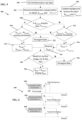
- the Image based handheld imager system comprises a two-step approach. First, an area scan camera 10 together with a cylindrical lens 12 are used to replace a line scan camera 14 and convex lens 16, as shown in Fig. 1 . Like a traditional SD-OCT system, the signal collimated by a collimator is dispersed through a grating.
- Fig. 1 illustrates one example that in the case of line scan sensor, where part of the signals are not captured due to tilt whereas in the case of area scan sensor, all the signals are captured by the sensor. As a result, the alignment tolerance compared with line scan sensor is greatly alleviated.
- the Image based handheld imager system includes a specific signal processing scheme to further mitigate the effect of misalignment.
- the signal processing scheme and associated algorithms are operable by a computer readable storage medium connected to a computer with a processor, which runs a software program or module to effectuate the signal processing scheme and associated algorithms.
- an area scan sensor After image is acquired, an average can be performed along the direction of same wavelength component. Such average operation greatly reduces the detector noise and increases the system's sensitivity and also provides a degree of freedom to correct the rotational angle due to misalignment as illustrated in Fig. 1.
- Fig. 2 illustrates the image processing procedures.
- a phantom for example a mirror may be placed in the sample arm at an appropriate depth such that the periodic fringe patterns can be clearly observed. If LCI is not used, known reference spectrum may be clearly observed rather than the periodic fringe pattern.
- the phantom is needed only once to find the tilt angle, but not needed in compensating the tilt angle. In one embodiment, the phantom is not needed during the use of the spectrometer but only needed in the alignment phase.
- a 2D image is acquired from the area scan sensor in step 110, the tilt angle due to alignment error regarding the average direction is identified and corrected in step 112.
- the Image based handheld imager system may employ an algorithm detects the tilt angle in step 114 and rotate the whole image according to this angle in step 116.
- the algorithm is based on the fact that if there is no tilt angle, the fringes orient perpendicular to the direction of average and hence no fringe washout occurs during averaging. If LCI is not used, known reference spectrum may be oriented perpendicular to the direction of average and hence no known reference spectrum washout occurs during averaging. The LCI signal after Fourier-transform in step 118 will be the largest compared to the case of fringe washout.
- a background subtraction step 120 is performed and a highest Signal-to-Noise (SNR) is obtained at step 122. If the highest SNR is not obtained, then the updated tilted angle step 114 and rotate image step 116 is performed again and then step 112 average along the vertical direction.
- SNR Signal-to-Noise
- a log display step 124 is performed.
- a maximum value search algorithm is developed to find the tilt angle.
- the detection of tilt angle is not necessary each time when the system is used.
- the detection of the tilt angle is only performed during the alignment process, and will be part of a calibration. This software correction can be equivalently achieved through changing the direction of average operation to the tilt angle while not rotating the image.
- Fig. 3 illustrates one configuration of the SD-OCT system 300.
- Light derived from a low-coherence source 320 such as a superluminescent diode (SLD), for example, is split by beam splitter 322 into a sample beam into a sample arm 324 and a reference beam into a reference arm 326 of the interferometer.
- the sample beam in the sample arm 324 is focused by focal optics in a handheld imager 328 onto sample, while reference beam is directed toward a free space reference arm 326 with a mirror 332 for reflecting light back into the interferometer.
- the handheld imager 328 may include focusing lens and mirror.
- the reference arm 326 may include polarization paddle 334.
- Light scattered by the sample is directed toward a detection arm 330 into a collimator 316, a grating 310, a cylindrical lens 312 and a sensor 314.
- the senor 314 is a consumer grade area scan camera using the Sony Pregius IMX249 sensor is employed.
- the sensor is a photodetector array is a two-dimensional array of detector elements, and is typically a CCD or CMOS, although any two-dimensional detector array is within the scope of the present invention.
- the OCT handheld imager system reaches >100 dB sensitivity at about 500 ⁇ m depth, ⁇ 1.65 dB roll off over 1mm imaging depth and >7 mm imaging depth. Fig.
- FIG. 3 illustrates the configuration of the SD-OCT system 300, according to one embodiment.
- the theoretical imaging depth of SD-OCT is directly determined by the sampling resolution of k component or wavelength in the interferometric signal, which also affects the roll-off parameter.
- an 1800 l/mm @ 840 nm grating 310 is used, according to one embodiment. If the FWHM is larger, a grating with a smaller l/mm can be used, where the choice of l/mm is also determined by the focal-length of the cylindrical lens and the 2D sensor size.
- 35 nm spectral bandwidth signal is dispersed and collimated into a 10 mm width beam, and then captured by a 2D sensor 314.
- a 2D sensor 3114 In one embodiment, the use of Sony Pregius IMX249 sensor which has about 5.86 ⁇ m pixel size leads to >7 mm imaging depth. Alternative imaging depths may be employed with alternative sensors.
- a 60 mm focal length lens 316 is used to collimate the signal emitting from the interferometer. The spot size is calculated to be about 8.15 ⁇ m at the area sensor, which reduces the cross talk at detection.
- the SD-OCT system achieved >7mm imaging depth and about a 1.6 dB roll off over about a 1 mm range using 20log 10 convention.
- the optics in the handheld imager provides about a 1 mm confocal parameter probing beam to ensure a stable beam profile around the focus. Due to the fact that area scan sensor is used, the raw data for each A-line signal is a 2D image. If LCI is not used, then then A-line signal is a signal of spectrum and may be a 1D image. After the 2D image is acquired, the signal is processed according to Fig. 2 to generate one A-line result. If LCI is not used, then after the 1D image is acquired, the signal is processed according to Fig. 2 to generate 1D spectrum result.
- the detection arm of the interferometer may comprise a spectrometer that may be incorporated into other imaging detection systems, such as not to be limited to LCI data.
- Fig. 4 illustrates an in-vivo LCI scanning result using the proposed system upon a healthy human subject.
- This result clearly indicates the thickness of tympanic membrane (TM) and demonstrates proposed utility in the clinical settings.
- the TM thickness at the imaging site is obtained by computing the distance between the two peaks in the LCI data, which correspond to the two layers of the TM, namely, the epidermal (outside) and the mucosal (inside) layer.
- the TM thickness at each imaging site was estimated as the average thickness obtained from a sequence of 100 depth resolved profiles, or A-lines, which were acquired at the speed of camera's frame rate.
- the frame rate is between about Tens of Hz to about 2 kHz.
- the Image based handheld imager system comprises a two-step approach to interpret the A-line data for clinical use, according to one embodiment.
- the OCT based handheld imager method 500 comprises a specific handling of LCI data 502 to generate useful A-line profiles utilizing both normal and mirrored results, which effectively double the imaging range of LCI.
- a background noise level is calculated to generate a flat background level for all the A-line results in the 1D interferometric data 502.
- a numerical dispersion compensation 504 with different parameters is performed, which might lead to different background profiles.
- two numerical dispersion compensations with different parameters are implemented to each raw interferometric data to generate two different A-line profiles, noted as A normal and A mirrored .
- each acquired raw interferometric data might be different from A-line to A-line caused by fiber twist, stretch, and the like.
- both A normal and A mirrored obtained from each raw interferometric data are averaged over all the current acquired data to obtain the noise background for normal and mirrored case 506, noted as N normal and N mirrored respectively.
- N normal and N mirrored will be the average over about hundreds of A-lines after several seconds.
- the number used for averaging includes a large number of A-lines, where the larger number is better; however the larger this number is, the longer time will be needed to acquire these number of A-lines. In one embodiment, averaging several hundreds of A-lines in several seconds is sufficient. In other embodiments, averaging at least a thousand A-lines in several seconds may suffice.
- the OCT based handheld imager method comprises subtracting A signal and A mirrored by N signal and N mirrored respectively and compared in terms of sharpness measurement 508, in order to determine whether the mirror image happens for the current acquired A-line.
- the one with overall higher sharpness is regarded as the correct A-line profile representation of the complex conjugate ambiguity.
- the sharpness is one quantitative metric that can be evaluated. Different OCT images or A-lines will lead to quite different sharpness measure.
- the material with high group delay dispersion into either one of the two arms of the OCT system is added resulting in a large dispersion mismatch between the two arms.
- the material with high group velocity dispersion is flint glass and in one embodiment the material is included only in the reference arm as the material in the sample arm may introduce unwanted attenuation. In other embodiments, the material with high group velocity dispersion is placed in the sample arm if optimal examples are more specific. In this way, the numerical dispersion compensation algorithm leads to more distinct A-line profile between A signal and A mirrored . For example in the case that A signal has a sharp peak where the A mirrored will have a broadened body of the peak with lower peak intensity. Sharpness is one quantitate metric of the A-line profile, which can also be evaluated in maximum intensity, and the like.
- a threshold check is performed regarding whether there is sufficient SNR for example, in one embodiment the maximum signal is 10 dB higher than the noise level for this A-line profile. In other embodiments, the sufficient SNR is to at least 3 dB above the noise level. If it passes the SNR check 510, then this A-line profile is regarded as useful 514, noted as A useful . In this case of mirrored image, A useful will be reversed 516 to keep display consistent with the normal LCI profile. If it does not pass the SNR check, then the A-line is disregarded. For display, there is no need to reverse back as all the mirrored images will be displayed in the same way (not consistent with normal LCI profile) such that user is not confused.
- the corresponding surface image is then analyzed 518 to determine whether this A-line scan is performed at the position of interest, which is the TM, according to one embodiment. If the corresponding surface image is performed at the position of interest 520, then regard this A useful as the final A-line profile for analysis and note it as A final .
- Fig. 5 illustrates the flowchart of these steps. If it does not passes the SNR check 512, then the data is disregarded 522 or A useful will be reversed 516 to keep display consistent with the normal LCI profile. For each A useful , if the corresponding surface image is then analyzed 518 to determine whether this A-line scan is not performed at the position of interest, then the data is disregarded 526.
- a specific analysis 600 is performed based on the useful A-line profile to provide better understandable results.
- the first peak along the depth profile is identified 602, which is expected to be the signal of the TM surface according one embodiment.
- the signal intensity after this peak is fitted to a curve.
- the steep slope is related to the axial resolution of the system and has an about 5-95% transition in the about 1-50 micron range.
- the thickness of human TM which is -100 ⁇ m, Paritosh Pande, Ryan L. Shelton, Guillermo L. Monroy, Ryan M.
- the result given to the clinicians could be the median of all the evaluated total thickness indicating the pathology of the TM.
- the distribution of total thicknesses can also be utilized to indicate the validity of measurement.
- the method implements a low cost handheld imager system based on SD-OCT using a consumer grade camera for otoscopic imaging in primary care settings. Further these proposed solutions can be applied to other applications, both medical and non-medical. Along with two novelties, such a system has sufficient sensitivity and stability for such applications.
- the Image based handheld imager system uses an area scan camera, which may be used in primary care settings for otoscopic imaging, or any imaging setting or configurations, such as for ophthalmoscope, dermatoscope, and the like.
- this Image based handheld imager system includes a relaxed alignment requirement without compromising image quality comprising using area scan camera with cylindrical lens and achieving similar SNR as traditional SDOCT; and a computer readable medium algorithm to further improve the robustness of alignment.
- the spectrometer design may be incorporated into other clinical imaging applications.
- the computer readable medium algorithm facilitate intelligent representation of low coherence interferometry (LCI) data comprising effective doubling imaging depth utilizing both normal and mirrored results; and identifying width of scattering signal in depth to characterize physiological features.
- LCDI low coherence interferometry
- the Image based handheld imager system uses an area scan camera together with the proposed processing method in the proposal leads to relaxed alignment requirements without compromising image quality. Additionally, lower cost is achieved, which assists towards adoption in primary care office.
- the Image based handheld imager system is different from A-line profile, as it directly provides the interpretation of A-line profile and effectively doubles the imaging range by utilizing the both normal and mirrored signals.
- A-line profile is used separately in some cases as needed, in addition to the automated interpretation.
- the tilt angle can be directly detected from the fringe orientation on the image acquired from a highly reflective phantom.
- a transparent material with two surfaces such as a cover glass or a microscopic slide can be inserted in front of the camera 2D sensor as a common path configuration. The period of the fringe pattern is then determined by the thickness of the material. After the fringe is acquired, the tilt angle can be identified by tracking the orientations of the local maxima and minima for the same spectral frequency components on the image.
- a computational wavefront correction scheme can be implemented.
- the 2D image which is the fringe pattern from a highly reflective phantom is measured.
- a Fourier transform is applied to the 2D image, and a phase filter is multiplied as the wavefront correction, which is then followed by an inverse Fourier transform.
- the correct fringe pattern from the same phantom is pre-determined using a well aligned spectrometer.
- a wavefront correction algorithm can be developed to search the best phase filter to best transform the captured fringe pattern into the correct fringe pattern.
- an M-mode image can be provided.
- the M-mode image updates for each newly acquired A-scan for users to better track the current position.
- the image analysis can be performed on the M-mode image instead of each individual A-line.
- the slope at where signals decrease to noise level at the medial side of the TM can be calculated as another feature to evaluate the existence of pathological material in the middle ear cavity.
- the LCI signal after TM quickly drops to noise level resulting in a very sharp slope.
- a graduate change of the LCI signal hence smaller slope is observed, it indicates the existence of pathological materials such as biofilm or effusion as disclosed in Cac T. Nguyen et al., "Noninvasive in vivo optical detection of biofilm in the human middle ear," Proc Natl Acad Sci 109(24), 9529-34, 2012 .
- a component can be, but is not limited to being, a process running on a processor, a processor, an object, an executable, a thread of execution, a program, and/or a computer.
- a component can be, but is not limited to being, a process running on a processor, a processor, an object, an executable, a thread of execution, a program, and/or a computer.
- an application running on a server and the server can be a component.
- One or more components can reside within a process and/or thread of execution, and a component can be localized on one computer and/or distributed between two or more computers.
- systems may include program modules, which may include routines, programs, components, data structures, etc. that perform particular tasks or implement particular abstract data types.
- inventive methods can be practiced with other computer system configurations, including single-processor or multiprocessor computer systems, minicomputers, mainframe computers, as well as personal computers, hand-held computing devices, microprocessor-based or programmable consumer electronics, and the like, each of which can be operatively coupled to one or more associated devices.
- the illustrated aspects of the innovation may also be practiced in distributed computing environments where certain tasks are performed by remote processing devices that are linked through a communications network.
- program modules can be located in both local and remote memory storage devices.
- Computer-readable media can be any available media that can be accessed by the computer and includes both volatile and nonvolatile media, removable and non-removable media.
- Computer-readable media can comprise computer storage media and communication media.
- Computer storage media includes volatile and nonvolatile, removable and non-removable media implemented in any method or technology for storage of information such as computer-readable instructions, data structures, program modules or other data.
- Computer storage media includes, but is not limited to, RAM, ROM, EEPROM, flash memory or other memory technology, CD-ROM, digital versatile disk (DVD) or other optical disk storage, magnetic cassettes, magnetic tape, magnetic disk storage or other magnetic storage devices, or any other medium which can be used to store the desired information and which can be accessed by the computer.
- Communication media typically embodies computer-readable instructions, data structures, program modules or other data in a modulated data signal such as a carrier wave or other transport mechanism, and includes any information delivery media.
- modulated data signal means a signal that has one or more of its characteristics set or changed in such a manner as to encode information in the signal.
- communication media includes wired media such as a wired network or direct-wired connection, and wireless media such as acoustic, RF, infrared and other wireless media. Combinations of the any of the above should also be included within the scope of computer-readable media.
- Software includes applications and algorithms.
- Software may be implemented in a smart phone, tablet, or personal computer, in the cloud, on a wearable device, or other computing or processing device.
- Software may include logs, journals, tables, games, recordings, communications, SMS messages, Web sites, charts, interactive tools, social networks, VOIP (Voice Over Internet Protocol), e-mails, and videos.
- VOIP Voice Over Internet Protocol
- e-mails and videos.
- computer readable program code includes any type of computer code, including source code, object code, executable code, firmware, software, etc.
- computer readable medium includes any type of medium capable of being accessed by a computer, such as read only memory (ROM), random access memory (RAM), a hard disk drive, a compact disc (CD), a digital video disc (DVD), or any other type of memory.
- ROM read only memory
- RAM random access memory
- CD compact disc
- DVD digital video disc
Landscapes
- Physics & Mathematics (AREA)
- Spectroscopy & Molecular Physics (AREA)
- General Physics & Mathematics (AREA)
- Health & Medical Sciences (AREA)
- General Health & Medical Sciences (AREA)
- Nuclear Medicine, Radiotherapy & Molecular Imaging (AREA)
- Radiology & Medical Imaging (AREA)
- Investigating Or Analysing Materials By Optical Means (AREA)
- Endoscopes (AREA)
Claims (7)
- Handhaltbares Spektrometer, umfassend:einen Detektionsarm (330), der einen Kollimator (316), ein Gitter (310), eine Zylinderlinse (312), einen 2D-Sensor (314) und einen Prozessor aufweist, der so konfiguriert ist, dass er ein von einer Probe reflektiertes Signal verarbeitet, um ein Spektrumssignal zu erzeugen, wobei das Spektrumssignal Rohdaten aufweist und die Rohdaten für jedes Spektrumssignal ein 2D-Bild sind, dadurch gekennzeichnet, dass der Prozessor so konfiguriert ist, dass er ein Signal verarbeitet, nachdem das 2D-Bild erfasst wurde, um einen Drehwinkel für eine Fehlausrichtung des 2D-Sensors (314) zu korrigieren, um ein 1D-Spektrumergebnis zu erzeugen,wobei der Prozessor konfiguriert ist, um das Signal zu verarbeiten, um einen Neigungswinkel aufgrund eines Ausrichtungsfehlers bezüglich einer durchschnittlichen Richtung zu identifizieren und den Neigungswinkel zu korrigieren,den korrekten Neigungswinkel zu detektieren und das 2D-Bild entsprechend des korrekten Neigungswinkels zu drehen,ein bekanntes Referenzspektrum senkrecht zu der durchschnittlichen Richtung auszurichten, wenn es keinen Neigungswinkel gibt und kein bekanntes Referenzspektrum-Auswaschen während der Mittelwertbildung auftritt,das Signal nach Verarbeitung einer Fourier-Transformation zu berechnen,einen Hintergrund zu subtrahieren und ein höchstes Signal-Rausch-Verhältnis, SNR, zu erhalten,wobei:wenn das höchste SNR nicht erhalten wird, dann Aktualisieren des Neigungswinkels, erneutes Drehen des Bildes und dann Mittelwertbildung entlang einer vertikalen Richtung; undwenn das höchste SNR erhalten wird, dann Durchführen einer Protokollanzeige.
- Spektrometer nach Anspruch 1, wobei das Detektieren des Neigungswinkels von dem Prozessor nur während eines Ausrichtungsprozesses des 2D-Sensors (314) durchgeführt wird.
- Spektrometer nach Anspruch 2, weiter umfassend einen Faserkoppler, der mit dem Detektionsarm (320) funktionsfähig gekoppelt ist.
- Spektrometer nach Anspruch 3, wobei der 2D-Sensor aus der Gruppe ausgewählt ist, die aus einer Flächenscankamera der Verbraucherklasse, einer Fotodetektoranordnung und einem zweidimensionalen Detektor besteht.
- Spektrometer nach Anspruch 4, wobei das bekannte Referenzspektrum ein Streifen ist.
- Spektrometer nach Anspruch 5, wobei das Gitter mindestens l/mm beträgt, um eine Wellenlängenabtastung zu erreichen.
- Spektrometer nach Anspruch 6, weiter umfassend einen Probenarm (324), der einen Spiegel (322) in einer geeigneten Tiefe aufweist, so dass eine Vielzahl periodischer Streifenmuster beobachtet wird.
Applications Claiming Priority (2)
| Application Number | Priority Date | Filing Date | Title |
|---|---|---|---|
| US201762464711P | 2017-02-28 | 2017-02-28 | |
| PCT/US2018/019951 WO2018160561A1 (en) | 2017-02-28 | 2018-02-27 | Image based handheld imager system and methods of use |
Publications (4)
| Publication Number | Publication Date |
|---|---|
| EP3589925A1 EP3589925A1 (de) | 2020-01-08 |
| EP3589925A4 EP3589925A4 (de) | 2021-04-14 |
| EP3589925B1 true EP3589925B1 (de) | 2024-09-25 |
| EP3589925C0 EP3589925C0 (de) | 2024-09-25 |
Family
ID=63371174
Family Applications (1)
| Application Number | Title | Priority Date | Filing Date |
|---|---|---|---|
| EP18761717.0A Active EP3589925B1 (de) | 2017-02-28 | 2018-02-27 | Bildbasiertes handhaltbares bildgebersystem |
Country Status (8)
| Country | Link |
|---|---|
| US (1) | US10809126B2 (de) |
| EP (1) | EP3589925B1 (de) |
| JP (1) | JP7558653B2 (de) |
| CN (1) | CN110383019B (de) |
| AU (1) | AU2018227432B2 (de) |
| CA (1) | CA3053171C (de) |
| IL (1) | IL268853B2 (de) |
| WO (1) | WO2018160561A1 (de) |
Families Citing this family (6)
| Publication number | Priority date | Publication date | Assignee | Title |
|---|---|---|---|---|
| US10357161B1 (en) | 2017-05-31 | 2019-07-23 | Otonexus Medical Technologies, Inc. | Infrared otoscope for characterization of effusion |
| US10568515B2 (en) | 2016-06-21 | 2020-02-25 | Otonexus Medical Technologies, Inc. | Optical coherence tomography device for otitis media |
| US20220225881A1 (en) * | 2016-06-21 | 2022-07-21 | Otonexus Medical Technologies, Inc. | Infrared otoscope for characterization of effusion |
| IL267820B2 (en) | 2017-01-06 | 2023-09-01 | Photonicare Inc | A self-orienting imaging system and method for use |
| EP3589925B1 (de) | 2017-02-28 | 2024-09-25 | Photonicare, Inc. | Bildbasiertes handhaltbares bildgebersystem |
| US20230380725A1 (en) * | 2020-10-18 | 2023-11-30 | Technion Research & Development Foundation Limited | System for in vivo measurements of tympanic membrane vibration |
Family Cites Families (29)
| Publication number | Priority date | Publication date | Assignee | Title |
|---|---|---|---|---|
| US6122538A (en) | 1997-01-16 | 2000-09-19 | Acuson Corporation | Motion--Monitoring method and system for medical devices |
| JP4038560B2 (ja) * | 2003-05-13 | 2008-01-30 | 国立大学法人 筑波大学 | 時間シアリング光コヒーレンストモグラフィー装置 |
| US7542138B2 (en) * | 2003-07-18 | 2009-06-02 | Chemimage Corporation | Sample container and system for a handheld spectrometer and method for using therefor |
| US7480058B2 (en) * | 2006-01-19 | 2009-01-20 | Optovue, Inc. | Fourier-domain optical coherence tomography imager |
| US8401257B2 (en) * | 2007-01-19 | 2013-03-19 | Bioptigen, Inc. | Methods, systems and computer program products for processing images generated using Fourier domain optical coherence tomography (FDOCT) |
| EP1962049B1 (de) * | 2007-02-21 | 2015-12-23 | Agfa HealthCare N.V. | System und Verfahren zur optischen Kohärenztomographie |
| US7812949B2 (en) * | 2007-10-17 | 2010-10-12 | Horiba Jobin Yvon Inc. | Spectrometer with cylindrical lens for astigmatism correction and demagnification |
| US8115934B2 (en) | 2008-01-18 | 2012-02-14 | The Board Of Trustees Of The University Of Illinois | Device and method for imaging the ear using optical coherence tomography |
| ES2517915T3 (es) * | 2008-06-02 | 2014-11-04 | Lightlab Imaging, Inc. | Métodos cuantitativos para obtener características de un tejido a partir de imágenes de tomografía por coherencia óptica |
| JP5255524B2 (ja) * | 2008-07-04 | 2013-08-07 | 株式会社ニデック | 光断層像撮影装置、光断層像処理装置。 |
| GB0812859D0 (en) * | 2008-07-14 | 2008-08-20 | Univ Cardiff | Method for image range extension in optical coherence tomography |
| JP5400481B2 (ja) * | 2009-06-03 | 2014-01-29 | 株式会社トプコン | 光画像計測装置 |
| US8594757B2 (en) | 2009-11-18 | 2013-11-26 | The Board Of Trustees Of The University Of Illinois | Apparatus for biomedical imaging |
| US8873049B2 (en) * | 2010-04-30 | 2014-10-28 | University Of Rochester | Broad band Czerny-Turner spectrometer, methods, and applications |
| US20120050746A1 (en) * | 2010-08-29 | 2012-03-01 | Shivani Sharma | Apparatus and method for increasing depth range and signal to noise ratio in fourier domain low coherence interferometry |
| US8564788B2 (en) * | 2011-07-26 | 2013-10-22 | Kabushiki Kaisha Topcon | Optical imaging method and optical imaging apparatus |
| JP5938926B2 (ja) * | 2012-01-31 | 2016-06-22 | 株式会社ニデック | 光断層像撮影装置及びノイズ除去方法 |
| US9095281B2 (en) * | 2012-02-10 | 2015-08-04 | Carl Zeiss Meditec, Inc. | Segmentation and enhanced visualization techniques for full-range fourier domain optical coherence tomography |
| KR101683408B1 (ko) * | 2012-10-05 | 2016-12-06 | 고쿠리츠다이가쿠호우징 카가와다이가쿠 | 분광 측정 장치 |
| US9867528B1 (en) | 2013-08-26 | 2018-01-16 | The Board Of Trustees Of The University Of Illinois | Quantitative pneumatic otoscopy using coherent light ranging techniques |
| US20160007840A1 (en) * | 2014-07-10 | 2016-01-14 | The Board Of Trustees Of The University Of Illinois | Handheld Device for Identification of Microbiological Constituents in the Middle Ear |
| US9638511B2 (en) | 2014-08-08 | 2017-05-02 | The Board Of Trustees Of The University Of Illinois | Smart phone attachment for 3-D optical coherence tomography imaging |
| CN104568754A (zh) * | 2014-12-26 | 2015-04-29 | 中国科学院苏州生物医学工程技术研究所 | 基于多谱段led光源的oct系统 |
| JP6598503B2 (ja) * | 2015-05-01 | 2019-10-30 | キヤノン株式会社 | 画像生成装置、画像生成方法及びプログラム |
| WO2016182999A1 (en) | 2015-05-08 | 2016-11-17 | Photonicare, Inc. | Otoscope tip and methods of use |
| JP7193343B2 (ja) * | 2016-02-19 | 2022-12-20 | オプトビュー,インコーポレーテッド | 機械学習技法を用いたoctアンギオグラフィにおけるアーチファクトを減少させるための方法及び装置 |
| CN105841824B (zh) * | 2016-03-23 | 2019-01-29 | 东南大学 | 一种非接触便携式温度实时测量装置 |
| IL267820B2 (en) | 2017-01-06 | 2023-09-01 | Photonicare Inc | A self-orienting imaging system and method for use |
| EP3589925B1 (de) | 2017-02-28 | 2024-09-25 | Photonicare, Inc. | Bildbasiertes handhaltbares bildgebersystem |
-
2018
- 2018-02-27 EP EP18761717.0A patent/EP3589925B1/de active Active
- 2018-02-27 JP JP2019546315A patent/JP7558653B2/ja active Active
- 2018-02-27 CN CN201880014253.0A patent/CN110383019B/zh active Active
- 2018-02-27 AU AU2018227432A patent/AU2018227432B2/en active Active
- 2018-02-27 CA CA3053171A patent/CA3053171C/en active Active
- 2018-02-27 WO PCT/US2018/019951 patent/WO2018160561A1/en not_active Ceased
- 2018-02-27 IL IL268853A patent/IL268853B2/en unknown
-
2019
- 2019-08-16 US US16/542,736 patent/US10809126B2/en active Active
Also Published As
| Publication number | Publication date |
|---|---|
| CN110383019A (zh) | 2019-10-25 |
| IL268853B2 (en) | 2024-08-01 |
| WO2018160561A1 (en) | 2018-09-07 |
| JP7558653B2 (ja) | 2024-10-01 |
| AU2018227432B2 (en) | 2022-09-29 |
| IL268853A (en) | 2019-10-31 |
| EP3589925A1 (de) | 2020-01-08 |
| US10809126B2 (en) | 2020-10-20 |
| US20190368929A1 (en) | 2019-12-05 |
| CA3053171A1 (en) | 2018-09-07 |
| CA3053171C (en) | 2024-02-13 |
| CN110383019B (zh) | 2022-07-05 |
| IL268853B1 (en) | 2024-04-01 |
| JP2020509375A (ja) | 2020-03-26 |
| AU2018227432A1 (en) | 2019-09-26 |
| EP3589925A4 (de) | 2021-04-14 |
| EP3589925C0 (de) | 2024-09-25 |
Similar Documents
| Publication | Publication Date | Title |
|---|---|---|
| EP3589925B1 (de) | Bildbasiertes handhaltbares bildgebersystem | |
| US8115934B2 (en) | Device and method for imaging the ear using optical coherence tomography | |
| US20030103212A1 (en) | Real-time imaging system and method | |
| JP6026406B2 (ja) | 眼構造の画像を改善するための装置 | |
| US20110170111A1 (en) | Optical coherence tomography (oct) apparatus, methods, and applications | |
| US20130250241A1 (en) | Variable resolution optical coherence tomography scanner and method for using same | |
| Zotter et al. | Measuring retinal nerve fiber layer birefringence, retardation, and thickness using wide-field, high-speed polarization sensitive spectral domain OCT | |
| Dsouza et al. | Economical and compact briefcase spectral-domain optical coherence tomography system for primary care and point-of-care applications | |
| Torzicky et al. | Retinal polarization-sensitive optical coherence tomography at 1060 nm with 350 kHz A-scan rate using an Fourier domain mode locked laser | |
| CN103961062B (zh) | 光学断层成像装置及其控制方法 | |
| Miao et al. | Numerical calibration method for a multiple spectrometer-based OCT system | |
| US11262183B2 (en) | Optical interference imaging device and its application | |
| Shirazi et al. | Dual-path handheld system for cornea and retina imaging using optical coherence tomography | |
| JP2007127425A (ja) | 光断層画像化法における補正方法 | |
| Hitzenberger et al. | MUW Approach of PS OCT | |
| Wang et al. | Highly reproducible swept-source, dispersion-encoded full-range biometry and imaging of the mouse eye | |
| Chen et al. | Spectrally extended line field optical coherence tomography angiography | |
| US20170095146A1 (en) | Combined optical thickness and physical thickness measurement | |
| JP4755934B2 (ja) | 波長可変レーザ装置および光断層画像化装置 | |
| HUANG | Megahertz multi-parametric ophthalmic OCT system for whole eye imaging | |
| Wang | Improving optical coherence tomography theories and techniques for advanced performance and reduced cost | |
| Li | Extending depth range of optical coherence tomography | |
| WO2013007967A1 (en) | Fourier domain oct | |
| Zhao | Spectral Domain Optical Coherence Tomography System Development for | |
| Kemp et al. | Birefringence of healthy in vivo primate RNFL with high sensitivity PS-OCT |
Legal Events
| Date | Code | Title | Description |
|---|---|---|---|
| STAA | Information on the status of an ep patent application or granted ep patent |
Free format text: STATUS: THE INTERNATIONAL PUBLICATION HAS BEEN MADE |
|
| PUAI | Public reference made under article 153(3) epc to a published international application that has entered the european phase |
Free format text: ORIGINAL CODE: 0009012 |
|
| STAA | Information on the status of an ep patent application or granted ep patent |
Free format text: STATUS: REQUEST FOR EXAMINATION WAS MADE |
|
| 17P | Request for examination filed |
Effective date: 20190927 |
|
| AK | Designated contracting states |
Kind code of ref document: A1 Designated state(s): AL AT BE BG CH CY CZ DE DK EE ES FI FR GB GR HR HU IE IS IT LI LT LU LV MC MK MT NL NO PL PT RO RS SE SI SK SM TR |
|
| RIN1 | Information on inventor provided before grant (corrected) |
Inventor name: ZHANG, ANQI Inventor name: SHELTON, RYAN Inventor name: KANG, WEI Inventor name: NOLAN, RYAN |
|
| RIC1 | Information provided on ipc code assigned before grant |
Ipc: G01B 9/02 20060101ALI20201202BHEP Ipc: G01J 3/45 20060101AFI20201202BHEP |
|
| A4 | Supplementary search report drawn up and despatched |
Effective date: 20210312 |
|
| RIC1 | Information provided on ipc code assigned before grant |
Ipc: G01J 3/45 20060101AFI20210305BHEP Ipc: G01B 9/02 20060101ALI20210305BHEP |
|
| STAA | Information on the status of an ep patent application or granted ep patent |
Free format text: STATUS: EXAMINATION IS IN PROGRESS |
|
| 17Q | First examination report despatched |
Effective date: 20230113 |
|
| REG | Reference to a national code |
Ref country code: DE Ref legal event code: R079 Free format text: PREVIOUS MAIN CLASS: G01J0003450000 Ipc: G01B0009020910 Ref document number: 602018074724 Country of ref document: DE |
|
| GRAP | Despatch of communication of intention to grant a patent |
Free format text: ORIGINAL CODE: EPIDOSNIGR1 |
|
| STAA | Information on the status of an ep patent application or granted ep patent |
Free format text: STATUS: GRANT OF PATENT IS INTENDED |
|
| RIC1 | Information provided on ipc code assigned before grant |
Ipc: G01J 3/18 20060101ALI20240404BHEP Ipc: G01J 3/02 20060101ALI20240404BHEP Ipc: G01B 9/02 20060101ALI20240404BHEP Ipc: G01J 3/45 20060101ALI20240404BHEP Ipc: G01B 9/02091 20220101AFI20240404BHEP |
|
| INTG | Intention to grant announced |
Effective date: 20240426 |
|
| GRAS | Grant fee paid |
Free format text: ORIGINAL CODE: EPIDOSNIGR3 |
|
| GRAA | (expected) grant |
Free format text: ORIGINAL CODE: 0009210 |
|
| STAA | Information on the status of an ep patent application or granted ep patent |
Free format text: STATUS: THE PATENT HAS BEEN GRANTED |
|
| RAP3 | Party data changed (applicant data changed or rights of an application transferred) |
Owner name: PHOTONICARE, INC. |
|
| AK | Designated contracting states |
Kind code of ref document: B1 Designated state(s): AL AT BE BG CH CY CZ DE DK EE ES FI FR GB GR HR HU IE IS IT LI LT LU LV MC MK MT NL NO PL PT RO RS SE SI SK SM TR |
|
| REG | Reference to a national code |
Ref country code: GB Ref legal event code: FG4D |
|
| REG | Reference to a national code |
Ref country code: CH Ref legal event code: EP |
|
| REG | Reference to a national code |
Ref country code: DE Ref legal event code: R096 Ref document number: 602018074724 Country of ref document: DE |
|
| REG | Reference to a national code |
Ref country code: IE Ref legal event code: FG4D |
|
| U01 | Request for unitary effect filed |
Effective date: 20241023 |
|
| U07 | Unitary effect registered |
Designated state(s): AT BE BG DE DK EE FI FR IT LT LU LV MT NL PT RO SE SI Effective date: 20241105 |
|
| PG25 | Lapsed in a contracting state [announced via postgrant information from national office to epo] |
Ref country code: NO Free format text: LAPSE BECAUSE OF FAILURE TO SUBMIT A TRANSLATION OF THE DESCRIPTION OR TO PAY THE FEE WITHIN THE PRESCRIBED TIME-LIMIT Effective date: 20241225 |
|
| PG25 | Lapsed in a contracting state [announced via postgrant information from national office to epo] |
Ref country code: GR Free format text: LAPSE BECAUSE OF FAILURE TO SUBMIT A TRANSLATION OF THE DESCRIPTION OR TO PAY THE FEE WITHIN THE PRESCRIBED TIME-LIMIT Effective date: 20241226 |
|
| PG25 | Lapsed in a contracting state [announced via postgrant information from national office to epo] |
Ref country code: RS Free format text: LAPSE BECAUSE OF FAILURE TO SUBMIT A TRANSLATION OF THE DESCRIPTION OR TO PAY THE FEE WITHIN THE PRESCRIBED TIME-LIMIT Effective date: 20241225 |
|
| PG25 | Lapsed in a contracting state [announced via postgrant information from national office to epo] |
Ref country code: RS Free format text: LAPSE BECAUSE OF FAILURE TO SUBMIT A TRANSLATION OF THE DESCRIPTION OR TO PAY THE FEE WITHIN THE PRESCRIBED TIME-LIMIT Effective date: 20241225 Ref country code: NO Free format text: LAPSE BECAUSE OF FAILURE TO SUBMIT A TRANSLATION OF THE DESCRIPTION OR TO PAY THE FEE WITHIN THE PRESCRIBED TIME-LIMIT Effective date: 20241225 Ref country code: GR Free format text: LAPSE BECAUSE OF FAILURE TO SUBMIT A TRANSLATION OF THE DESCRIPTION OR TO PAY THE FEE WITHIN THE PRESCRIBED TIME-LIMIT Effective date: 20241226 |
|
| U20 | Renewal fee for the european patent with unitary effect paid |
Year of fee payment: 8 Effective date: 20250227 |
|
| PG25 | Lapsed in a contracting state [announced via postgrant information from national office to epo] |
Ref country code: IS Free format text: LAPSE BECAUSE OF FAILURE TO SUBMIT A TRANSLATION OF THE DESCRIPTION OR TO PAY THE FEE WITHIN THE PRESCRIBED TIME-LIMIT Effective date: 20250125 |
|
| PG25 | Lapsed in a contracting state [announced via postgrant information from national office to epo] |
Ref country code: SM Free format text: LAPSE BECAUSE OF FAILURE TO SUBMIT A TRANSLATION OF THE DESCRIPTION OR TO PAY THE FEE WITHIN THE PRESCRIBED TIME-LIMIT Effective date: 20240925 |
|
| PG25 | Lapsed in a contracting state [announced via postgrant information from national office to epo] |
Ref country code: ES Free format text: LAPSE BECAUSE OF FAILURE TO SUBMIT A TRANSLATION OF THE DESCRIPTION OR TO PAY THE FEE WITHIN THE PRESCRIBED TIME-LIMIT Effective date: 20240925 |
|
| PG25 | Lapsed in a contracting state [announced via postgrant information from national office to epo] |
Ref country code: PL Free format text: LAPSE BECAUSE OF FAILURE TO SUBMIT A TRANSLATION OF THE DESCRIPTION OR TO PAY THE FEE WITHIN THE PRESCRIBED TIME-LIMIT Effective date: 20240925 Ref country code: CZ Free format text: LAPSE BECAUSE OF FAILURE TO SUBMIT A TRANSLATION OF THE DESCRIPTION OR TO PAY THE FEE WITHIN THE PRESCRIBED TIME-LIMIT Effective date: 20240925 |
|
| PG25 | Lapsed in a contracting state [announced via postgrant information from national office to epo] |
Ref country code: SK Free format text: LAPSE BECAUSE OF FAILURE TO SUBMIT A TRANSLATION OF THE DESCRIPTION OR TO PAY THE FEE WITHIN THE PRESCRIBED TIME-LIMIT Effective date: 20240925 |
|
| PLBE | No opposition filed within time limit |
Free format text: ORIGINAL CODE: 0009261 |
|
| STAA | Information on the status of an ep patent application or granted ep patent |
Free format text: STATUS: NO OPPOSITION FILED WITHIN TIME LIMIT |
|
| 26N | No opposition filed |
Effective date: 20250626 |
|
| PG25 | Lapsed in a contracting state [announced via postgrant information from national office to epo] |
Ref country code: MC Free format text: LAPSE BECAUSE OF FAILURE TO SUBMIT A TRANSLATION OF THE DESCRIPTION OR TO PAY THE FEE WITHIN THE PRESCRIBED TIME-LIMIT Effective date: 20240925 |
|
| REG | Reference to a national code |
Ref country code: CH Ref legal event code: PL |
|
| PG25 | Lapsed in a contracting state [announced via postgrant information from national office to epo] |
Ref country code: CH Free format text: LAPSE BECAUSE OF NON-PAYMENT OF DUE FEES Effective date: 20250228 |
|
| GBPC | Gb: european patent ceased through non-payment of renewal fee |
Effective date: 20250227 |