EP3589829B1 - Verfahren zum betreiben einer verbrennungskraftmaschine eines hybridkraftfahrzeugs während eines startvorgangs genannter verbrennungskraftmaschine - Google Patents
Verfahren zum betreiben einer verbrennungskraftmaschine eines hybridkraftfahrzeugs während eines startvorgangs genannter verbrennungskraftmaschine Download PDFInfo
- Publication number
- EP3589829B1 EP3589829B1 EP18711023.4A EP18711023A EP3589829B1 EP 3589829 B1 EP3589829 B1 EP 3589829B1 EP 18711023 A EP18711023 A EP 18711023A EP 3589829 B1 EP3589829 B1 EP 3589829B1
- Authority
- EP
- European Patent Office
- Prior art keywords
- combustion engine
- internal combustion
- torque
- maximum permissible
- lubricant
- Prior art date
- Legal status (The legal status is an assumption and is not a legal conclusion. Google has not performed a legal analysis and makes no representation as to the accuracy of the status listed.)
- Active
Links
Images


Classifications
-
- F—MECHANICAL ENGINEERING; LIGHTING; HEATING; WEAPONS; BLASTING
- F02—COMBUSTION ENGINES; HOT-GAS OR COMBUSTION-PRODUCT ENGINE PLANTS
- F02D—CONTROLLING COMBUSTION ENGINES
- F02D41/00—Electrical control of supply of combustible mixture or its constituents
- F02D41/02—Circuit arrangements for generating control signals
- F02D41/04—Introducing corrections for particular operating conditions
- F02D41/06—Introducing corrections for particular operating conditions for engine starting or warming up
- F02D41/062—Introducing corrections for particular operating conditions for engine starting or warming up for starting
-
- B—PERFORMING OPERATIONS; TRANSPORTING
- B60—VEHICLES IN GENERAL
- B60W—CONJOINT CONTROL OF VEHICLE SUB-UNITS OF DIFFERENT TYPE OR DIFFERENT FUNCTION; CONTROL SYSTEMS SPECIALLY ADAPTED FOR HYBRID VEHICLES; ROAD VEHICLE DRIVE CONTROL SYSTEMS FOR PURPOSES NOT RELATED TO THE CONTROL OF A PARTICULAR SUB-UNIT
- B60W20/00—Control systems specially adapted for hybrid vehicles
- B60W20/40—Controlling the engagement or disengagement of prime movers, e.g. for transition between prime movers
-
- B—PERFORMING OPERATIONS; TRANSPORTING
- B60—VEHICLES IN GENERAL
- B60W—CONJOINT CONTROL OF VEHICLE SUB-UNITS OF DIFFERENT TYPE OR DIFFERENT FUNCTION; CONTROL SYSTEMS SPECIALLY ADAPTED FOR HYBRID VEHICLES; ROAD VEHICLE DRIVE CONTROL SYSTEMS FOR PURPOSES NOT RELATED TO THE CONTROL OF A PARTICULAR SUB-UNIT
- B60W30/00—Purposes of road vehicle drive control systems not related to the control of a particular sub-unit, e.g. of systems using conjoint control of vehicle sub-units
- B60W30/18—Propelling the vehicle
- B60W30/192—Mitigating problems related to power-up or power-down of the driveline, e.g. start-up of a cold engine
-
- B—PERFORMING OPERATIONS; TRANSPORTING
- B60—VEHICLES IN GENERAL
- B60W—CONJOINT CONTROL OF VEHICLE SUB-UNITS OF DIFFERENT TYPE OR DIFFERENT FUNCTION; CONTROL SYSTEMS SPECIALLY ADAPTED FOR HYBRID VEHICLES; ROAD VEHICLE DRIVE CONTROL SYSTEMS FOR PURPOSES NOT RELATED TO THE CONTROL OF A PARTICULAR SUB-UNIT
- B60W30/00—Purposes of road vehicle drive control systems not related to the control of a particular sub-unit, e.g. of systems using conjoint control of vehicle sub-units
- B60W30/18—Propelling the vehicle
- B60W30/192—Mitigating problems related to power-up or power-down of the driveline, e.g. start-up of a cold engine
- B60W30/194—Mitigating problems related to power-up or power-down of the driveline, e.g. start-up of a cold engine related to low temperature conditions, e.g. high viscosity of hydraulic fluid
-
- B—PERFORMING OPERATIONS; TRANSPORTING
- B60—VEHICLES IN GENERAL
- B60W—CONJOINT CONTROL OF VEHICLE SUB-UNITS OF DIFFERENT TYPE OR DIFFERENT FUNCTION; CONTROL SYSTEMS SPECIALLY ADAPTED FOR HYBRID VEHICLES; ROAD VEHICLE DRIVE CONTROL SYSTEMS FOR PURPOSES NOT RELATED TO THE CONTROL OF A PARTICULAR SUB-UNIT
- B60W30/00—Purposes of road vehicle drive control systems not related to the control of a particular sub-unit, e.g. of systems using conjoint control of vehicle sub-units
- B60W30/18—Propelling the vehicle
- B60W30/18009—Propelling the vehicle related to particular drive situations
- B60W30/18072—Coasting
- B60W2030/1809—Without torque flow between driveshaft and engine, e.g. with clutch disengaged or transmission in neutral
-
- B—PERFORMING OPERATIONS; TRANSPORTING
- B60—VEHICLES IN GENERAL
- B60W—CONJOINT CONTROL OF VEHICLE SUB-UNITS OF DIFFERENT TYPE OR DIFFERENT FUNCTION; CONTROL SYSTEMS SPECIALLY ADAPTED FOR HYBRID VEHICLES; ROAD VEHICLE DRIVE CONTROL SYSTEMS FOR PURPOSES NOT RELATED TO THE CONTROL OF A PARTICULAR SUB-UNIT
- B60W2510/00—Input parameters relating to a particular sub-units
- B60W2510/06—Combustion engines, Gas turbines
- B60W2510/0676—Engine temperature
-
- B—PERFORMING OPERATIONS; TRANSPORTING
- B60—VEHICLES IN GENERAL
- B60W—CONJOINT CONTROL OF VEHICLE SUB-UNITS OF DIFFERENT TYPE OR DIFFERENT FUNCTION; CONTROL SYSTEMS SPECIALLY ADAPTED FOR HYBRID VEHICLES; ROAD VEHICLE DRIVE CONTROL SYSTEMS FOR PURPOSES NOT RELATED TO THE CONTROL OF A PARTICULAR SUB-UNIT
- B60W2710/00—Output or target parameters relating to a particular sub-units
- B60W2710/08—Electric propulsion units
- B60W2710/083—Torque
-
- B—PERFORMING OPERATIONS; TRANSPORTING
- B60—VEHICLES IN GENERAL
- B60Y—INDEXING SCHEME RELATING TO ASPECTS CROSS-CUTTING VEHICLE TECHNOLOGY
- B60Y2306/00—Other features of vehicle sub-units
- B60Y2306/03—Lubrication
-
- F—MECHANICAL ENGINEERING; LIGHTING; HEATING; WEAPONS; BLASTING
- F02—COMBUSTION ENGINES; HOT-GAS OR COMBUSTION-PRODUCT ENGINE PLANTS
- F02D—CONTROLLING COMBUSTION ENGINES
- F02D2200/00—Input parameters for engine control
- F02D2200/02—Input parameters for engine control the parameters being related to the engine
- F02D2200/023—Temperature of lubricating oil or working fluid
-
- F—MECHANICAL ENGINEERING; LIGHTING; HEATING; WEAPONS; BLASTING
- F02—COMBUSTION ENGINES; HOT-GAS OR COMBUSTION-PRODUCT ENGINE PLANTS
- F02D—CONTROLLING COMBUSTION ENGINES
- F02D2250/00—Engine control related to specific problems or objectives
- F02D2250/18—Control of the engine output torque
- F02D2250/26—Control of the engine output torque by applying a torque limit
-
- F—MECHANICAL ENGINEERING; LIGHTING; HEATING; WEAPONS; BLASTING
- F02—COMBUSTION ENGINES; HOT-GAS OR COMBUSTION-PRODUCT ENGINE PLANTS
- F02N—STARTING OF COMBUSTION ENGINES; STARTING AIDS FOR SUCH ENGINES, NOT OTHERWISE PROVIDED FOR
- F02N2200/00—Parameters used for control of starting apparatus
- F02N2200/02—Parameters used for control of starting apparatus said parameters being related to the engine
- F02N2200/024—Engine oil temperature
Definitions
- the invention relates to a method for operating an internal combustion engine of a motor vehicle, in particular a hybrid vehicle, during a starting process of the internal combustion engine, in particular during a starting process from a standstill of the internal combustion engine to high torques. Furthermore, the invention relates to an engine control system for carrying out the method according to the invention and to a motor vehicle with such an engine control system.
- Hybrid vehicles typically have an internal combustion engine and an electric motor, each of which provides a drive torque as a proportion of the total torque. As described in the DE 10 2007 055 740 A1 and the DE 10 2013 004 033 A1 As described, the individual moments of the combustion engine and the electric machine are coordinated with each other.
- a driver request may cause the internal combustion engine to operate immediately at high load. Due to a lack of lubrication or a delayed oil pressure buildup, the immediate load request can lead to component damage to bearings, such as the crankshaft, connecting rods, or the turbocharging system due to solid or mixed lubrication.
- the internal combustion engine can be lubricated (started) while running electrically to fill the oil gallery and supply the internal combustion engine components with oil.
- lubrication of the internal combustion engine is not possible due to driving conditions. This can still lead to potential damage to the internal combustion engine.
- the DE 10 2011 005 803 A1 describes a method for operating a hybrid vehicle, wherein an internal combustion engine is only switched on when a requested desired torque is at least higher by a difference amount than the maximum torque that can be achieved by an electric motor.
- the DE 10 2012 009 481 A1 describes a method for controlling the connection of an internal combustion engine of a hybrid drive unit, wherein the internal combustion engine is operated in a first phase after starting at a torque which is reduced compared to a target torque and the torque is then increased to the target torque in a second phase as soon as an engine temperature has reached a predetermined temperature.
- the US 2012/067327 A1 Describes a method in which a maximum torque is determined depending on engine temperature and engine speed. Additionally, the maximum torque can depend on a pressure ratio between the air supply and the exhaust tract.
- the DE 10 2011 078 446 A1 describes a method whereby a maximum torque during cold start is determined depending on ambient conditions, for example an ambient temperature.
- the US 2011/0146622 A1 discloses a method for limiting a torque depending on an engine temperature, a time since exceeding an engine speed or a time since exceeding an engine speed and an engine pressure.
- the object of the present invention is to provide a method and an engine control for operating an internal combustion engine of a motor vehicle during a starting process of the internal combustion engine, which at least partially overcome the above-mentioned disadvantages.
- the invention relates to an engine control for operating an internal combustion engine of a motor vehicle during a starting process of the internal combustion engine, which engine control is designed to carry out a method according to the first aspect.
- the present invention relates to a method for operating an internal combustion engine of a motor vehicle during a starting process of the internal combustion engine, in particular during a starting process of the internal combustion engine from a standstill to high torques, preferably maximum torques.
- a starting process is also referred to as a critical initial start of the internal combustion engine.
- the method according to the invention is thus used when the internal combustion engine is operated directly at high load from a standstill of the internal combustion engine.
- the starting process can be a start of the internal combustion engine from a purely electric operating mode of the hybrid vehicle and/or a start during a hybrid operating mode of the hybrid vehicle. Alternatively or additionally, the starting process can be a start during coasting operation of the hybrid vehicle. In a vehicle with the If the internal combustion engine, for example a gasoline engine or a diesel internal combustion engine, is the only drive element, the starting process can be a start during sailing operation of the vehicle.
- the internal combustion engine for example a gasoline engine or a diesel internal combustion engine
- a lubrication state variable is obtained that represents a lubrication state of the internal combustion engine.
- the lubrication state of the internal combustion engine can be a distribution of a lubricant, for example, engine oil, on one or more components of the internal combustion engine that are subject to a frictional force.
- the components of the internal combustion engine include, for example, one or more components of a crankshaft drive, such as a crankshaft, connecting rods (pistons), connecting rods, and/or the like, and/or one or more components of a charging system, such as an exhaust gas turbocharger, an exhaust flap, and/or the like.
- the lubrication state variable can, for example, be detected by a sensor or generated and provided by an analysis unit, for example in the form of a processor, using one or more models, and then received, in particular, by an engine control unit. Examples of the lubrication state variable are listed and explained below.
- a maximum permissible torque of the internal combustion engine (maximum permissible internal combustion engine torque) is determined depending on the obtained lubrication state variable.
- the maximum permissible torque is a torque limit dependent on the lubrication state variable. If exceeded, mixed friction occurs on the components of the internal combustion engine, leading to undesirable wear.
- the maximum permissible torque can, for example, be determined using models and stored as a characteristic curve or map and/or calculated mathematically. Details on determining the maximum permissible torque are described in more detail below.
- the internal combustion engine is operated, in particular started and operated, at an operating torque which corresponds to or is less than the determined maximum permissible torque.
- lubrication By operating the internal combustion engine during the start-up process below full load, i.e., below the maximum possible torque or maximum available torque, lubrication can be initiated, reducing or preventing mixed friction and predominantly maintaining the desired sliding friction. This provides the internal combustion engine with the appropriate protection to prevent damage to the internal combustion engine or to the engine and engine components.
- the lubrication state variable may include a lubricant temperature of a lubricant in the internal combustion engine, a lubricant pressure of the lubricant in the internal combustion engine, a time after the end of a standstill of the internal combustion engine, a coolant temperature of the internal combustion engine, a coolant pressure of the internal combustion engine, a number of combustions and/or crankshaft revolutions since the end of the standstill of the internal combustion engine, a duration of a previous standstill of the internal combustion engine, a duration since a previous lubrication process of the internal combustion engine, a duration of a previous operation of the internal combustion engine, a duration of a previous lubrication process of the internal combustion engine, a property of a previous lubrication process and/or another lubrication state variable.
- the lubricant temperature can be a temperature of the lubricant in a lubricant circuit of the internal combustion engine, for example, an oil temperature in an oil gallery or in an oil line of the lubricant circuit.
- the lubricant temperature can be detected by a temperature sensor in the lubricant circuit, for example, in the oil gallery or in the oil line, and/or provided by a model, in particular a lubricant temperature model.
- the lubricant pressure of the lubricant can be a pressure of the lubricant in the lubricant circuit and detected by a pressure sensor in the lubricant circuit and/or provided by a model, in particular a lubricant pressure model.
- the time after the end of the standstill of the internal combustion engine i.e. since the start of the starting process of the internal combustion engine, and/or the number of combustions and/or crankshaft revolutions since the end of the standstill of the internal combustion engine, i.e. since the start of the starting process of the internal combustion engine, can be derived, for example, from a signal of a crankshaft sensor.
- the duration of the previous standstill of the internal combustion engine for example a shutdown duration of the internal combustion engine, the duration since the previous lubrication process of the internal combustion engine, the duration of the previous operation of the internal combustion engine, the duration of the previous lubrication process of the internal combustion engine, i.e. a previous combustion runtime, can be recorded by means of time measurement, for example triggered by a stored crankshaft signal of a crankshaft sensor.
- the property of the previous lubrication process may include, for example, a lubricant and/or coolant temperature or a lubricant and/or coolant pressure, a number of combustions and/or crankshaft revolutions during the previous lubrication process and/or another property.
- the maximum permissible torque of the internal combustion engine can increase with an increase in the lubrication state variable during the starting process of the internal combustion engine.
- the maximum permissible torque can preferably increase continuously, for example, linearly, quadratically, or exponentially.
- the maximum permissible torque is limited and subsequently ramped or increased to a maximum available torque.
- a maximum permissible base torque value can be determined based on the lubricant temperature. Based on the maximum permissible base torque value, a maximum limited permissible torque can then be calculated with increasing with time after the combustion engine starts. Depending on the relationship between lubricant temperature and coolant temperature, the maximum permissible base torque can be adjusted. Additionally or alternatively, the maximum permissible torque can be increased to the maximum available torque after a specified number of combustion cycles since start-up.
- a maximum permissible basic torque can be determined depending on the time after the end of the standstill of the internal combustion engine and depending on the lubricant temperature of the lubricant in the internal combustion engine or the lubricant pressure of the lubricant in the internal combustion engine.
- the maximum permissible basic torque value results from the lubricant temperature and the maximum permissible basic torque increases from the maximum permissible basic torque value with increasing time after the combustion engine start.
- the maximum permissible basic torque can be determined and/or calculated mathematically, for example, by means of a characteristic curve or a characteristic map, for example a characteristic map over the time after the combustion engine start and the lubricant temperature.
- an adjustment factor may be determined depending on the lubricant temperature and/or the coolant temperature, and the maximum allowable base torque may be adjusted depending on the determined adjustment factor.
- the adjustment factor can be read or derived from a characteristic curve or a characteristic map.
- the characteristic curve or characteristic map can preferably be generated using models based on experimental measurements.
- the adjustment factor can be read from a characteristic map of the lubrication and coolant temperatures, which reflects a relationship between the lubrication and coolant temperatures on the one hand and the lubrication condition of the internal combustion engine on the other.
- the maximum permissible combustion torque can be limited depending on the lubricant or coolant temperature and then adjusted over time according to The combustion engine can be ramped or increased to its maximum (maximum available torque) during a critical start. This significantly minimizes wear on the combustion engine during a critical start.
- the maximum permissible base torque or the adjusted maximum permissible base torque can be increased to the maximum available torque (maximum possible torque) after a predetermined number of combustion cycles and/or a predetermined number of crankshaft revolutions of the internal combustion engine since the end of the standstill of the internal combustion engine.
- the predetermined number of combustion cycles can be a number of combustion cycles after which the internal combustion engine is sufficiently lubricated so that sliding friction prevails even at high or maximum load.
- the predetermined number of combustion cycles can be determined experimentally or using a model. The same applies to the number of crankshaft revolutions.
- an increase factor can be determined depending on the duration of the previous standstill of the internal combustion engine, the duration since the previous lubrication process of the internal combustion engine, the duration of the previous operation of the internal combustion engine, and/or the duration of the previous lubrication process of the internal combustion engine, and the maximum permissible base torque or the adjusted maximum permissible base torque can be adjusted depending on the determined increase factor.
- the increase factor can preferably be equal to or greater than 1.
- the increase factor can be read or derived from a characteristic curve or a characteristic map.
- the characteristic curve or characteristic map can preferably be generated using models based on experimental measurements.
- the increase factor can be read from a return flow characteristic curve, which reflects the dependence of a lubricant level of the internal combustion engine on a lubrication-free period or the duration of the internal combustion engine's standstill.
- the lubricant level preferably indicates how much of the lubricant has remained in an oil gallery and/or has flowed back into an oil reservoir of the internal combustion engine.
- a return flow characteristic map can also be used.
- a first factor can be determined based on the duration of the previous operation of the internal combustion engine and the duration of the previous lubrication process of the internal combustion engine.
- a second factor can be determined based on the duration of the previous downtime of the internal combustion engine and the duration since the previous lubrication process of the internal combustion engine. The first factor and the second factor can then be combined to form the increase factor. Alternatively, the first factor or the second factor can be used as the increase factor.
- the critical start can therefore also be assessed based on the duration of the last lubrication process or the last combustion runtime. Additionally or alternatively, the critical start can also be assessed based on a long engine shutdown period or a lubrication process that occurred a long time ago. Long shutdown times lead to the lubricant flowing back into the oil pan and the oil gallery running dry.
- the operating torque when a maximum possible torque is requested, the operating torque may correspond to the maximum allowable torque during the start-up process.
- the maximum permissible torque of the internal combustion engine can be set, whereby the maximum permissible torque during the starting process approaches the maximum possible torque and corresponds to the maximum possible torque at the end of the starting process.
- the internal combustion engine which is an internal combustion engine of a hybrid vehicle that further comprises an electric drive motor or other drive
- the starting process can only occur from a purely electric operating mode of the hybrid vehicle and/or during a hybrid operating mode of the hybrid vehicle.
- the starting process can be a start during coasting operation of the hybrid vehicle.
- the method according to the invention for operating an internal combustion engine of a motor vehicle during a starting process enables needs-based protection of the internal combustion engine and associated components against damage, a reduction of mechanical wear on components and thus an increased service life of the components.
- the present invention further relates to an engine control for operating an internal combustion engine of a motor vehicle during a starting process of the internal combustion engine, wherein the engine control is designed to carry out a method for operating an internal combustion engine of a motor vehicle during a starting process, as described above.
- the engine control is designed to receive a lubrication state variable that represents a lubrication state of the internal combustion engine, to determine a maximum permissible torque of the internal combustion engine depending on the lubrication state variable, and to operate the internal combustion engine at an operating torque that corresponds to or is less than the determined maximum permissible torque of the internal combustion engine.
- the engine control unit may comprise a processor, for example a microprocessor, designed to execute the described method according to the invention.
- the engine control unit may further comprise a data memory, in which a program is preferably stored that contains instructions for the processor to control it according to the described method.
- Characteristic curves, characteristic maps, and/or other parameters necessary for executing the method for example, the above-mentioned models, characteristic curves, characteristic maps, and/or other parameters, may also be stored in the data memory.
- the engine control unit can have a number of signal inputs and outputs. Data such as the lubrication status can be received via the signal inputs.
- the internal combustion engine can be controlled via the signal outputs.
- the present invention relates to a motor vehicle with an internal combustion engine, for example a gasoline engine or a diesel engine, and an engine control system designed as described above.
- an internal combustion engine for example a gasoline engine or a diesel engine
- an engine control system designed as described above for example a gasoline engine or a diesel engine
- the motor vehicle may be a hybrid vehicle with an internal combustion engine and an electric drive motor.
- the hybrid vehicle may be a parallel hybrid vehicle.
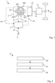
- the hybrid vehicle 1 comprises a drive train with a drive device 2, which is connected to a drive axle 12 via a crankshaft 10 and a transmission 11 in order to move wheels of the hybrid vehicle 1 connected to the drive axle 12.
- the drive device 2 has, as drive units, an internal combustion engine 20 with a lubricant circuit 200 and a coolant circuit 201, and an electric machine 21 (electric machine).
- the hybrid vehicle 1 has, as shown in Fig. 1 shown, also has an engine control unit 3.
- the engine control unit 3 is connected via a data line 40 to an oil temperature sensor 202 in the lubricant circuit 200, via a data line 41 to a cooling water temperature sensor 203 in the coolant circuit 201, and via a data line to a crankshaft angle sensor (not shown) in order to receive an oil temperature detected by the oil temperature sensor 202, a cooling water temperature detected by the cooling water temperature sensor 203, or a crankshaft signal detected by the crankshaft angle sensor.
- the engine control unit 3 is connected via a data line 42 to the internal combustion engine 20 and via a data line 43 to the electric motor 21 in order to control the internal combustion engine 20 and the electric motor 21, respectively.
- the engine control unit 3 is connected via a data line 44 to a sensor (not shown) on an accelerator pedal 5 in order to receive a control signal containing a driver command.
- the engine control is designed to carry out a method 6 for operating the internal combustion engine 30 during a starting process of the internal combustion engine 30 from a standstill, as described below with reference to Fig. 2
- the starting process can be carried out from electric driving mode in hybrid operating mode or from purely electric operating mode.
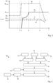
- FIG. 3 An exemplary curve of the driver's desired torque M F , which includes a strong increase in the driver's desired torque, is shown in Fig. 3 shown.
- the driver's desired torque M F is constant at a first value M F,0 , which can be provided solely by the electric motor. Accordingly, before t 1 , a speed n e of the electric motor is constant at a value n e,max and the internal combustion engine is at a standstill.
- the driver's desired torque M F increases abruptly with a steep gradient to a second value M F,max , which remains constant until time t 2.
- the speed n e of the electric motor is constant at the value n e,max and after a short delay, a speed n v of the internal combustion engine increases at t 3 to a value n v,max .
- the driver's desired torque M F drops to a lower value. Accordingly, the speed n v of the internal combustion engine also decreases.
- a maximum permissible internal combustion engine torque M v,z is determined continuously during the entire starting process of the internal combustion engine between t 1 and t 4. The determination of the maximum permissible internal combustion engine torque M v,z is described further below with reference to Fig. 4 explained.
- the internal combustion engine is controlled as a function of the desired internal combustion engine torque and the maximum permissible internal combustion engine torque M v,z .
- Fig. 4 explains the determination 61 of the maximum permissible combustion engine torque M v,z .
- an oil temperature T ö which is detected by the oil temperature sensor arranged in the lubricant circuit of the internal combustion engine, is received. Since the oil temperature T ö changes only imperceptibly during the start-up process of the internal combustion engine, the oil temperature is received at the beginning of the start-up process of the internal combustion engine.
- a maximum permissible base torque M v,g is determined depending on the oil temperature T ö and the time t vs since the end of the standstill or the beginning of the starting process of the internal combustion engine.
- a model is stored in the data memory of the engine control unit, for example, the one in Fig. 5
- the map shows that the maximum permissible base torque M v,g is greater and increases more rapidly with time, the higher the oil temperature T ö1 , T ö2 , T ö3 is, with the oil temperature increasing from T ö1 to T ö3 .
- a coolant temperature T K is received, which is detected by the cooling water temperature sensor arranged in the coolant circuit of the internal combustion engine.
- the coolant temperature T K also changes only imperceptibly during the start-up process of the internal combustion engine and is therefore only received at the beginning of the start-up process of the internal combustion engine.
- an adjustment factor Fa is determined based on the oil temperature Tö and the cooling water temperature Tk .
- the adjustment factor Fa is read from a characteristic map of the oil temperature Tö and the coolant temperature Tk , which reflects a relationship between the oil temperature Tö and the coolant temperature Tk on the one hand and the lubrication condition of the internal combustion engine on the other.
- a characteristic map which is stored in the data memory of the engine control unit, is in Fig. 6 shown as an example.
- Fig. 6 shows that the adjustment factor F a takes on values around 1 and increases with increasing cooling water temperature T K.
- the adjustment factor F a is lower at low oil temperatures T ö1 than at high oil temperatures T ö3 .
- the maximum permissible base torque M v,g is adjusted depending on the specific adjustment factor Fa .
- a limit on the maximum permissible torque is adjusted accordingly.
- crankshaft sensor signal is received and by evaluating the crankshaft sensor signal (cylinder counter) a number of combustions since the start of the starting process is determined.
- the adjusted maximum permissible torque is ramped up or increased to the maximum available combustion engine torque M v,max .
- the duration of the previous standstill of the internal combustion engine, the duration since the previous lubrication process of the internal combustion engine, the duration of the previous operation of the internal combustion engine, and/or the duration of the previous lubrication process of the internal combustion engine are determined by evaluating a stored crankshaft sensor signal.
- the stored crankshaft sensor signal is stored in the data memory and extends over a period of time that encompasses an interval from a previous start of the internal combustion engine to the beginning of the start process of the internal combustion engine.
- an increase factor F E is determined depending on the duration of the previous standstill of the internal combustion engine, the duration since the previous lubrication process of the internal combustion engine, the duration of the previous operation of the internal combustion engine and the duration of the previous lubrication process of the internal combustion engine.
- the increase factor F E is equal to or greater than 1. The determination 79 of the increase factor F E is described below with reference to the Fig. 7 explained.
- a first factor F E1 is determined depending on the duration D B of the previous operation of the internal combustion engine and the duration D S of the previous lubrication process of the internal combustion engine.
- Fig. 8 shows two exemplary curves of the first factor F E1 depending on the duration D B of the previous operation of the Internal combustion engine for the durations D S1 , D S2 of the previous lubrication process of the internal combustion engine, where D S1 is shorter than D S2 .
- a second factor F E2 is determined depending on the duration D R of the previous standstill of the internal combustion engine and the duration D O since the previous lubrication process of the internal combustion engine.
- Fig. 9 shows, as an example, two courses of the second factor F E2 as a function of the duration D R of the previous standstill of the internal combustion engine and the duration D O since the previous lubrication process of the internal combustion engine, where D O1 is shorter than D O2 .
- the first factor F E1 and the second factor F E2 are then combined to form the increase factor F E , whereby the increase factor is never less than 1.
- the smaller of the first and second factors F E1 , F E2 is adopted.
- the increase factor F E can be set to greater than 1. This means that the torque limitation is no longer as severe.
- the maximum permissible combustion engine torque is determined by adjusting the adjusted maximum permissible base torque depending on the determined increase factor F E. If the increase factor F E is equal to 1, the maximum permissible base torque corresponds to the adjusted maximum permissible base torque and, if the increase factor F E is greater than 1, the adjusted maximum permissible base torque is increased.
- the maximum permissible torque M v,z is in Fig. 3 shown.
- the maximum permissible torque M v,z rises steeply after t 3 to a value M v,z1 and then increases in a ramp to the maximum possible torque M v,max .
- the maximum permissible internal combustion engine torque M v,z remains at the maximum possible torque M v,max .
Landscapes
- Engineering & Computer Science (AREA)
- Mechanical Engineering (AREA)
- Automation & Control Theory (AREA)
- Transportation (AREA)
- Chemical & Material Sciences (AREA)
- Combustion & Propulsion (AREA)
- General Engineering & Computer Science (AREA)
- Combined Controls Of Internal Combustion Engines (AREA)
Description
- Die Erfindung betrifft ein Verfahren zum Betreiben einer Verbrennungskraftmaschine eines Kraftfahrzeugs, insbesondere eines Hybridfahrzeugs, während eines Startvorgangs der Verbrennungskraftmaschine, insbesondere während eines Startvorgangs aus einem Stillstand der Verbrennungskraftmaschine auf hohe Drehmomente. Weiterhin betrifft die Erfindung eine Motorsteuerung zum Ausführen des erfindungsgemäßen Verfahrens und ein Kraftfahrzeug mit einer solchen Motorsteuerung.
- Hybridfahrzeuge weisen üblicherweise einen Verbrennungsmotor und eine elektrische Maschine auf, die jeweils ein Antriebsmoment als Anteil an einem Gesamtmoment stellen. Wie in der
DE 10 2007 055 740 A1 und derDE 10 2013 004 033 A1 beschrieben, werden die einzelnen Momente des Verbrennungsmotors und der elektrischen Maschine aufeinander abgestimmt. - In einem Fahrzeug mit Parallelhybridantriebsstrang mit einer Trennkupplung zwischen der Verbrennungskraftmaschine und dem restlichem Antriebsstrang kann es auf Grund einer Fahrerwunschanforderung vorkommen, dass die Verbrennungskraftmaschine direkt mit hoher Last betrieben wird. Auf Grund fehlender Schmierung bzw. zeitlich verzögertem Öldruckaufbau kann es durch die sofortige Lastanforderung zu Bauteilschädigung an Lagern, wie beispielsweise der Kurbelwelle, Pleuel oder am Aufladesystem auf Grund von Festkörper- oder Mischschmierung kommen.
- Um einen solchen Verschleiß zu verringern, kann die Verbrennungskraftmaschine im elektrischen Betrieb geschmiert (angedreht) werden, um so die Ölgalerie zu befüllen bzw. die Bauteile der Verbrennungskraftmaschine mit Öl zu versorgen. Es gibt allerdings Situationen, in denen ein Schmieren der Verbrennungskraftmaschine auf Grund der Fahrsituationen nicht durchgeführt werden kann. Somit kann es weiterhin zu einer möglichen Schädigung der Verbrennungskraftmaschine kommen.
- Die
DE 10 2011 005 803 A1 beschreibt ein Verfahren zum Betreiben eines Hybridfahrzeugs, wobei ein Verbrennungsmotor nur zugeschaltet wird, wenn ein angefordertes Wunschmoment mindestens um einen Differenzbetrag höher ist als ein maximal durch einen Elektromotor erzielbares Moment. - Die
DE 10 2012 009 481 A1 beschreibt ein Verfahren zur Steuerung einer Zuschaltung eines Verbrennungsmotors einer Hybridantriebseinheit, wobei der Verbrennungsmotor in einer ersten Phase nach dem Start bei einem gegenüber einem Zieldrehmoment abgesenkten Drehmoment betrieben wird und das Drehmoment anschließend, sobald eine Motortemperatur eine vorgegebene Temperatur erreicht hat, in einer zweiten Phase auf das Zieldrehmoment angehoben wird. - Die
US 2012/067327 A1 beschreibt ein Verfahren, bei dem in Abhängigkeit einer Motortemperatur und einer Motorgeschwindigkeit ein maximales Drehmoment bestimmt wird. Zusätzlich kann das maximale Drehmoment von einem Druckverhältnis zwischen Luftzuführung und Abgastrakt abhängen. - Die
DE 10 2011 078 446 A1 beschreibt ein Verfahren, wobei ein maximales Drehmoment beim Kaltstart in Abhängigkeit von Umgebungsbedingungen, beispielsweise einer Umgebungstemperatur, bestimmt wird. - Die
US 2011/0146622 A1 offenbart ein Verfahren zum Begrenzen eines Drehmoments in Abhängigkeit einer Motortemperatur, einer Zeit seit Überschreiten einer Motorgeschwindigkeit oder einer Zeit seit Überschreiten einer Motorgeschwindigkeit und eines Motordrucks. - Durch das Bereitstellen eines reduzierten Moments durch die Verbrennungskraftmaschine kann es jedoch zu unerwünschten Einbußen im Fahrkomfort kommen, da das Wunschmoment nicht unmittelbar bereitgestellt werden kann.
- Aufgabe der vorliegenden Erfindung ist es, ein Verfahren und eine Motorsteuerung zum Betreiben einer Verbrennungskraftmaschine eines Kraftfahrzeugs während eines Startvorgangs der Verbrennungskraftmaschine bereitzustellen, die die oben genannten Nachteile wenigstens teilweise überwinden.
- Diese Aufgabe wird durch das erfindungsgemäße Verfahren zum Betreiben einer Verbrennungskraftmaschine eines Kraftfahrzeugs während eines Startvorgangs der Verbrennungskraftmaschine nach Anspruch 1 und die erfindungsgemäße Motorsteuerung nach Anspruch 6 gelöst.
- Gemäß einem ersten Aspekt betrifft die Erfindung ein Verfahren zum Betreiben einer Verbrennungskraftmaschine eines Kraftfahrzeugs während eines Startvorgangs der Verbrennungskraftmaschine, umfassend:
- Erhalten einer Schmierzustandsgröße, die einen Schmierzustand der
- Verbrennungskraftmaschine abbildet;
- Bestimmen eines maximal zulässigen Drehmoments der Verbrennungskraftmaschine abhängig von der Schmierzustandsgröße; und
- Betreiben der Verbrennungskraftmaschine bei einem Betriebsdrehmoment, das dem bestimmten maximal zulässigen Drehmoment entspricht oder kleiner als dieses ist.
- Gemäß einem zweiten Aspekt betrifft die Erfindung eine Motorsteuerung zum Betreiben einer Verbrennungskraftmaschine eines Kraftfahrzeugs während eines Startvorgangs der Verbrennungskraftmaschine, die dazu ausgebildet ist, ein Verfahren nach dem ersten Aspekt auszuführen.
- Weitere vorteilhafte Ausgestaltungen der Erfindung ergeben sich aus den Unteransprüchen und der folgenden Beschreibung bevorzugter Ausführungsbeispiele der vorliegenden Erfindung.
- Die vorliegende Erfindung betrifft ein Verfahren zum Betreiben einer Verbrennungskraftmaschine eines Kraftfahrzeugs während eines Startvorgangs der Verbrennungskraftmaschine, insbesondere während eines Startvorgangs der Verbrennungskraftmaschine aus einem Stillstand auf hohe Drehmomente, vorzugsweise maximale Drehmomente. Ein solcher Startvorgang wird auch als kritischer Zustart der Verbrennungskraftmaschine bezeichnet. Das erfindungsgemäße Verfahren findet somit Anwendung, wenn die Verbrennungskraftmaschine ausgehend von einem Stillstand der Verbrennungskraftmaschine direkt mit hoher Last betrieben wird.
- Bei einem Hybridfahrzeug mit einer elektrischen Antriebsmaschine und der Verbrennungskraftmaschine, die beispielsweise ein Ottomotor oder ein Dieselmotor sein kann, kann der Startvorgang ein Start der Verbrennungskraftmaschine aus einem rein elektrischen Betriebsmodus des Hybridfahrzeugs und/oder ein Start während eines hybridischen Betriebsmodus des Hybridfahrzeugs sein. Alternativ oder zusätzlich kann der Startvorgang ein Start während eines Segelbetriebs des Hybridfahrzeugs sein. Bei einem Fahrzeug mit der Verbrennungskraftmaschine, beispielsweise einem Ottomotor oder einer DieselBrennkraftmaschine, als einzigem Antriebselement kann der Startvorgang ein Start während eines Segelbetriebs des Fahrzeugs sein.
- Gemäß dem erfindungsgemäßen Verfahren wird eine Schmierzustandsgröße erhalten, die einen Schmierzustand der Verbrennungskraftmaschine abbildet. Der Schmierzustand der Verbrennungskraftmaschine kann eine Verteilung eines Schmiermittels, beispielsweise von Motoröl, auf einem oder mehreren Bauteilen der Verbrennungskraftmaschine, die einer Reibkraft ausgesetzt sind, sein. Die Bauteile der Verbrennungskraftmaschine umfassen beispielsweise eine oder mehrere Komponenten eines Kurbeltriebs, wie eine Kurbelwelle, Pleuel (Kolben), Pleuelstangen und/oder dergleichen, und/oder eine oder mehrere Komponenten eines Aufladesystems, wie einen Abgasturbolader, eine Abgasklappe und/oder dergleichen, umfassen.
- Die Schmierzustandsgröße kann beispielsweise von einem Sensor erfasst sein bzw. von einer Analyseeinheit beispielsweise in Form eines Prozessors zum Beispiel mit Hilfe eines oder mehrerer Modelle erzeugt und bereitgestellt sein und anschließend insbesondere von einer Motorsteuerung empfangen werden. Beispiele für die Schmierzustandsgröße werden weiter unten aufgelistet und erklärt.
- Weiterhin wird gemäß dem erfindungsgemäßen Verfahren abhängig von der erhaltenen Schmierzustandsgröße ein maximal zulässiges Drehmoment der Verbrennungskraftmaschine (maximal zulässiges verbrennungsmotorisches Drehmoment) bestimmt. Das maximal zulässige Drehmoment ist eine von der Schmierzustandsgröße abhängige Drehmomentgrenze, bei deren Überschreiten eine Mischreibung an den Bauteilen der Verbrennungskraftmaschine auftritt, die zu einem unerwünschten Verschleiß dieser führt.
- Das maximal zulässige Drehmoment kann beispielsweise anhand von Modellen ermittelt sein und als Kennlinie oder Kennfeld hinterlegt sein und/oder mathematisch berechnet sein. Details zur Bestimmung des maximal zulässigen Drehmoments werden weiter unten im Detail beschrieben.
- Anschließend wird gemäß dem erfindungsgemäßen Verfahren die Verbrennungskraftmaschine bei einem Betriebsdrehmoment betrieben, insbesondere gestartet und betrieben, das dem bestimmten maximal zulässigen Drehmoment entspricht oder kleiner als dieses ist.
- Durch den Betrieb der Verbrennungskraftmaschine während des Startvorgangs unterhalb einer Volllast, d.h. unterhalb eines maximal möglichen Drehmoments bzw. eines maximal abrufbaren Drehmoments kann eine Schmierung in Gang gesetzt werden, so dass eine Mischreibung verringert bzw. vermieden wird und sich vorwiegend eine gewünschte Gleitreibung einstellt. Es erfolgt somit ein bedarfsgerechter Schutz der Verbrennungskraftmaschine, um Schäden an der Verbrennungskraftmaschine bzw. an einem Triebwerk und Triebwerkskomponenten zu vermeiden.
- In manchen Ausführungsbeispielen kann die Schmierzustandsgröße eine Schmiermitteltemperatur eines Schmiermittels in der Verbrennungskraftmaschine, ein Schmiermitteldruck des Schmiermittels in der Verbrennungskraftmaschine, eine Zeit nach einem Ende eines Stillstands der Verbrennungskraftmaschine, eine Kühlmitteltemperatur der Verbrennungskraftmaschine, ein Kühlmitteldruck der Verbrennungskraftmaschine, eine Anzahl an Verbrennungen und/oder Kurbelwellenumdrehungen seit dem Ende des Stillstands der Verbrennungskraftmaschine, eine Dauer eines vorangegangenen Stillstands der Verbrennungskraftmaschine, eine Dauer seit einem vorangegangen Schmiervorgang der Verbrennungskraftmaschine, eine Dauer eines vorangegangenen Betriebs der Verbrennungskraftmaschine, eine Dauer eines vorangegangenen Schmiervorgangs der Verbrennungskraftmaschine, eine Eigenschaft eines vorangegangenen Schmiervorgangs und/oder eine andere Schmierzustandsgröße umfassen.
- Die Schmiermitteltemperatur kann eine Temperatur des Schmiermittels in einem Schmiermittelkreislauf der Verbrennungskraftmaschine sein, beispielsweise eine Öltemperatur in einer Ölgalerie oder in einer Ölleitung des Schmiermittelkreislaufs. Die Schmiermitteltemperatur kann von einem Temperatursensor in dem Schmiermittelkreislauf, beispielsweise in der Ölgalerie oder in der Ölleitung, erfasst sein und/oder durch ein Modell, insbesondere ein Schmiermitteltemperaturmodell, bereitgestellt sein. Entsprechend kann der Schmiermitteldruck des Schmiermittels ein Druck des Schmiermittels in dem Schmiermittelkreislauf sein und von einem Drucksensor in dem Schmiermittelkreislauf erfasst und/oder durch ein Modell, insbesondere ein Schmiermitteldruckmodel, bereitgestellt sein.
- Die Kühlmitteltemperatur der Verbrennungskraftmaschine kann eine Temperatur eines Kühlmittels, beispielsweise von Kühlwasser, in einem Kühlkreislauf der Verbrennungskraftmaschine sein und mittels eines Temperatursensors, der in dem Kühlkreislauf angeordnet ist, erfasst und/oder durch ein Modell, insbesondere ein Kühlmitteltemperaturmodell, bereitgestellt sein. Entsprechend kann der Kühlmitteldruck des Kühlmittels ein Druck des Kühlmittels in dem Kühlkreislauf sein und von einem Drucksensor in dem Kühlkreislauf erfasst und/oder durch ein Modell, insbesondere ein Kühlmitteldruckmodell, bereitgestellt sein.
- Die Zeit nach einem Ende des Stillstands der Verbrennungskraftmaschine, d.h. seit Beginn des Startvorgangs der Verbrennungskraftmaschine, und/oder die Anzahl an Verbrennungen und/oder an Kurbelwellenumdrehzungen seit dem Ende des Stillstands der Verbrennungskraftmaschine, d.h. seit Beginn des Startvorgangs der Verbrennungskraftmaschine, können beispielsweise aus einem Signal eines Kurbelwellensensors abgeleitet sein.
- Die Dauer des vorangegangenen Stillstands der Verbrennungskraftmaschine, beispielsweise eine Abstelldauer der Verbrennungskraftmaschine, die Dauer seit dem vorangegangenen Schmiervorgang der Verbrennungskraftmaschine, die Dauer des vorangegangenen Betriebs der Verbrennungskraftmaschine, die Dauer des vorangegangenen Schmiervorgangs der Verbrennungskraftmaschine, d.h. eine vorangegangene Verbrennungslaufzeit, können mittels Zeitmessung erfasst sein, beispielsweise getriggert durch ein gespeichertes Kurbelwellensignal eines Kurbelwellensensors.
- Die Eigenschaft des vorangegangenen Schmiervorgangs kann beispielsweise eine Schmiermittel- und/oder Kühlmitteltemperatur bzw. einen Schmiermittel- und/oder Kühlmitteldruck, eine Anzahl der Verbrennungen und/oder Kurbelwellenumdrehungen während des vorangegangenen Schmiervorgangs und/oder eine andere Eigenschaft umfassen.
- In manchen Ausführungsbeispielen kann das maximal zulässige Drehmoment der Verbrennungskraftmaschine mit einem Anstieg der Schmierzustandsgröße während des Startvorgangs der Verbrennungskraftmaschine steigen. Das maximal zulässige Drehmoment kann vorzugsweise kontinuierlich, beispielsweise linear, quadratisch oder exponentiell, steigen. Somit wird in Situationen, in denen ein kritischer Zustart der Verbrennungskraftmaschine, d.h. ein Start aus dem Stillstand auf hohe Drehmomente, erfolgt, das maximal zulässige Drehmoment begrenzt und anschließend auf ein maximal abrufbares Drehmoment verrampt bzw. vergrößert.
- Beispielsweise kann ausgehend von der Schmiermitteltemperatur ein maximal zulässiger Drehmomentgrundwert bestimmt werden. Ausgehend von dem maximal zulässigen Drehmomentgrundwert kann ein maximal begrenztes zulässiges Drehmoment dann mit steigender Zeit nach dem Verbrennerstart ansteigen. Abhängig von einem Zusammenhang zwischen Schmiermitteltemperatur und Kühlmitteltemperatur kann der maximal begrenzte zulässige Drehmomentgrundwert angepasst werden. Zusätzlich oder alternativ kann das maximal zulässige Drehmoment nach einer vorgegebenen Anzahl an Verbrennungen seit dem Start auf das maximal abrufbare Drehmoment angehoben werden.
- In manchen Ausführungsbeispielen kann abhängig von der Zeit nach dem Ende des Stillstands der Verbrennungskraftmaschine sowie abhängig von der Schmiermitteltemperatur des Schmiermittels in der Verbrennungskraftmaschine oder des Schmiermitteldrucks des Schmiermittels in der Verbrennungskraftmaschine ein maximal zulässiges Grunddrehmoment bestimmt werden.
- Da es während des Startvorgang nur zu geringen Veränderung der Schmiermitteltemperatur in der Verbrennungskraftmaschine kommt, ergibt sich der maximal zulässige Drehmomentgrundwert aus der Schmiermitteltemperatur und das maximal zulässige Grunddrehmoment nimmt ausgehend von dem maximal zulässigen Drehmomentgrundwert mit steigender Zeit nach dem Verbrennerstart zu.
- Das maximal zulässige Grunddrehmoment kann beispielsweise mittels einer Kennlinie oder eines Kennfelds, beispielsweise eines Kennfelds über die Zeit nach dem Verbrennerstart und die Schmiermitteltemperatur, bestimmt werden und/oder mathematisch berechnet sein.
- In manchen Ausführungsbeispielen kann abhängig von der Schmiermitteltemperatur und/oder der Kühlmitteltemperatur ein Anpassungsfaktor bestimmt werden und das maximal zulässige Grunddrehmoment abhängig von dem bestimmten Anpassungsfaktor anpasst werden.
- Der Anpassungsfaktor kann aus einer Kennlinie oder einem Kennfeld abgelesen bzw. abgeleitet werden. Die Kennlinie bzw. das Kennfeld können vorzugsweise auf Grundlage von experimentellen Messungen mittels Modellen erzeugt sein. Beispielsweise kann der Anpassungsfaktor aus einem Kennfeld über die Schmier- und die Kühlmitteltemperatur abgelesen werden, die einen Zusammenhang zwischen der Schmier- und Kühlmitteltemperatur einerseits und dem Schmierzustand der Verbrennungskraftmaschine andererseits widergibt.
- Somit kann im Falle eines kritischen Zustarts der Verbrennungskraftmaschine in Abhängigkeit der Schmiermittel- bzw. Kühlmitteltemperatur das maximale zulässige Verbrennermoment (maximal zulässiges Drehmoment) begrenzt und anschließend über die Zeit nach Verbrennerstart auf sein Maximum (maximal abrufbares Drehmoment) verrampt bzw. vergrößert werden. Dadurch lässt sich der Verschleiß der Verbrennungskraftmaschine bei einem kritischen Zustart dieser deutlich minimieren.
- In manchen Ausführungsbeispielen kann das maximal zulässige Grunddrehmoment bzw. das angepasste maximal zulässige Grunddrehmoment nach einer vorgegebenen Anzahl an Verbrennungen und/oder einer vorgegebenen Anzahl an Kurbelwellenumdrehungen der Verbrennungskraftmaschine seit dem Ende des Stillstands der Verbrennungskraftmaschine auf das maximal abrufbare Drehmoment (maximal mögliches Drehmoment) erhöht werden. Die vorgegebene Anzahl der Verbrennungen kann eine Anzahl an Verbrennungen sein, nach der die Verbrennungskraftmaschine ausreichend geschmiert ist, so dass auch bei hoher bzw. maximaler Last vorwiegend Gleitreibung herrscht. Die vorgegebene Anzahl der Verbrennungen kann experimentell bestimmt sein oder mittels eines Modells bestimmt sein. Analoges gilt für die Anzahl an Kurbelwellenumdrehungen.
- Damit kann verhindert werden, dass das Verbrennermoment über einen unnötig langen Zeitraum begrenzt ist.
- In manchen Ausführungsbeispielen kann abhängig von der Dauer des vorangegangenen Stillstands der Verbrennungskraftmaschine, der Dauer seit dem vorangegangenen Schmiervorgang der Verbrennungskraftmaschine, der Dauer des vorangegangenen Betriebs der Verbrennungskraftmaschine und/oder der Dauer des vorangegangenen Schmiervorgangs der Verbrennungskraftmaschine ein Erhöhungsfaktor bestimmt werden und das maximal zulässige Grunddrehmoment bzw. das angepasste maximal zulässige Grunddrehmoment abhängig von dem bestimmten Erhöhungsfaktor anpasst werden. Vorzugsweise kann der Erhöhungsfaktor gleich oder größer 1 sein.
- Der Erhöhungsfaktor kann aus einer Kennlinie oder einem Kennfeld abgelesen bzw. abgeleitet werden. Die Kennlinie bzw. das Kennfeld können vorzugsweise auf Grundlage von experimentellen Messungen mittels Modellen erzeugt sein. Beispielsweise kann der Erhöhungsfaktor aus einer Rückflusskennlinie abgelesen werden, die eine Abhängigkeit eines Schmiermittelstands der Verbrennungskraftmaschine von einer schmierungsfreien Zeit bzw. der Dauer der Stillstands der Verbrennungskraftmaschine widergibt. Der Schmiermittelstand gibt vorzugsweise an, wieviel des Schmiermittels in einer Ölgalerie verblieben ist und/oder in einen Ölbehälter der Verbrennungskraftmaschine zurückgeflossen ist. Alternativ kann auch ein Rückflusskennfeld herangezogen werden.
- Beispielsweise kann ein erster Faktor abhängig von der Dauer des vorangegangenen Betriebs der Verbrennungskraftmaschine und der Dauer des vorangegangenen Schmiervorgangs der Verbrennungskraftmaschine bestimmt werden. Außerdem oder alternativ kann ein zweiter Faktor abhängig von der Dauer des vorangegangenen Stillstands der Verbrennungskraftmaschine und der Dauer seit dem vorangegangenen Schmiervorgang der Verbrennungskraftmaschine bestimmt werden. Der erste Faktor und der zweite Faktor können dann zu dem Erhöhungsfaktor kombiniert werden. Alternativ kann der erste Faktor oder der zweite Faktor als Erhöhungsfaktor zum Einsatz kommen.
- Der kritische Zustart kann somit zusätzlich über die Dauer des letzten Schmiervorgangs bzw. der letzten Verbrennerlaufzeit bewertet werden. Zusätzlich oder alternativ kann der kritische Zustart auch über eine lange Motorabstelldauer bzw. einen sehr lang zurückliegenden Schmiervorgang bewertet werden. Lange Abstellzeiten führen zu einem Rücklaufen des Schmiermittels in einer Ölwanne und einem Leerlaufen der Ölgalerie.
- In manchen Ausführungsbeispielen kann das Betriebsdrehmoment, wenn ein maximal mögliches Drehmoment angefordert wird, während des Startvorgangs dem maximal zulässigen Drehmoment entsprechen.
- Wenn es zum Erfüllen eines Fahrerwunschmoments notwendig ist, dass ein maximal mögliches Drehmoment eingestellt wird, kann somit das maximal zulässige Drehmoment der Verbrennungskraftmaschine eingestellt werden, wobei sich das maximal zulässige Drehmoment während des Startvorgangs an das maximal mögliche Drehmoment annähert und dem maximal möglichen Drehmoment zum Ende des Startvorgangs entspricht.
- In manchen Ausführungsbeispielen kann die Verbrennungskraftmaschine, die eine Verbrennungskraftmaschine eines Hybridfahrzeugs ist, das weiterhin eine elektrische Antriebsmaschine oder einen anderen Antrieb aufweist, während eines Betriebs der elektrischen Antriebsmaschine oder des anderen Antriebs gestartet werden. Wie oben bereits erwähnt, kann der Startvorgang nur aus einem rein elektrischen Betriebsmodus des Hybridfahrzeugs und/oder während eines hybridischen Betriebsmodus des Hybridfahrzeugs erfolgen. Alternativ oder zusätzlich kann der Startvorgang ein Start während eines Segelbetriebs des Hybridfahrzeugs sein.
- Das erfindungsgemäße Verfahren zum Betreiben einer Verbrennungskraftmaschine eines Kraftfahrzeugs während eines Startvorgangs ermöglicht einen bedarfsgerechten Schutz der Verbrennungskraftmaschine und zugehöriger Bauteile vor einer Schädigung, eine Reduktion von mechanischem Verschleiß an Bauteilen und damit ein erhöhte Lebensdauer der Komponenten.
- Die vorliegende Erfindung betrifft weiterhin eine Motorsteuerung zum Betreiben einer Verbrennungskraftmaschine eines Kraftfahrzeugs während eines Startvorgangs der Verbrennungskraftmaschine, wobei die Motorsteuerung dazu ausgebildet ist, ein Verfahren zum Betreiben einer Verbrennungskraftmaschine eines Kraftfahrzeugs während eines Startvorgangs, wie es voranstehend beschrieben ist, auszuführen.
- Die Motorsteuerung ist dazu ausgebildet, eine Schmierzustandsgröße zu erhalten, die einen Schmierzustand der Verbrennungskraftmaschine abbildet, abhängig von der Schmierzustandsgröße ein maximal zulässiges Drehmoment der Verbrennungskraftmaschine zu bestimmen und die Verbrennungskraftmaschine bei einem Betriebsdrehmoment, das dem bestimmten maximal zulässigen Drehmoment der Verbrennungskraftmaschine entspricht oder kleiner als dieses ist, zu betreiben.
- Die Motorsteuerung kann einen Prozessor, beispielsweise einen Mikroprozessor, aufweisen, der dazu ausgebildet ist, das beschriebene erfindungsgemäße Verfahren auszuführen. Die Motorsteuerung kann weiterhin einen Datenspeicher aufweisen, in dem vorzugsweise ein Programm hinterlegt ist, das Anweisungen für den Prozessor enthält, um diesen entsprechend dem beschriebenen Verfahren zu steuern. In dem Datenspeicher können zudem Kennlinien, Kennfelder und/oder andere Parameter, die zum Ausführen des Verfahrens notwendig sind, beispielsweise die oben erwähnten, Modelle, Kennlinien, Kennfelder und/oder anderen Parameter, hinterlegt sein.
- Die Motorsteuerung kann eine Reihe von Signaleingängen und Signalausgängen aufweisen. Über die Signaleingänge können beispielsweise Daten wie die Schmierzustandsgröße empfangen werden. Über die Signalausgänge kann die Verbrennungskraftmaschine angesteuert werden.
- Die vorliegende Erfindung betrifft ein Kraftfahrzeug mit einer Verbrennungskraftmaschine, beispielsweise einem Ottomotor oder einem Dieselmotor, und einer Motorsteuerung, die wie oben beschrieben ausgebildet ist.
- Das Kraftfahrzeug kann ein Hybridfahrzeug mit der Verbrennungskraftmaschine und einer elektrischen Antriebsmaschine sein. Beispielsweise kann das Hybridfahrzeug ein Parallelhybridfahrzeug sein.
- Ausführungsbeispiele der Erfindung werden nun beispielhaft und unter Bezugnahme auf die beigefügten Zeichnungen beschrieben. Es zeigen:
- Fig. 1
- eine schematische Darstellung eines erfindungsgemäßen Hybridfahrzeugs;
- Fig. 2
- ein Flussdiagramm eines Verfahrens zum Betreiben einer Verbrennungskraftmaschine eines Kraftfahrzeugs während eines Startvorgangs aus einem Stillstand auf hohe Lasten;
- Fig. 3
- eine Darstellung eines Verlaufs eines maximal zulässigen Drehmoments der Verbrennungskraftmaschine;
- Fig. 4
- ein Flussdiagramm eines Verfahrens zum Bestimmen des maximal zulässigen Drehmoments der Verbrennungskraftmaschine;
- Fig. 5
- eine schematische Darstellung eines maximal zulässigen Grunddrehmoments der Verbrennungskraftmaschine in Abhängigkeit einer Öltemperatur und einer Zeit seit einem Ende eines Stillstands der Verbrennungskraftmaschine;
- Fig. 6
- eine schematische Darstellung eines Anpassungsfaktors in Abhängigkeit der Öltemperatur und einer Kühltemperatur;
- Fig. 7
- ein Flussdiagramm eines Verfahrens zum Bestimmen eines Erhöhungsfaktors;
- Fig. 8
- eine schematische Darstellung eines ersten Faktors in Abhängigkeit einer Dauer eines vorangegangenen Betriebs der Verbrennungskraftmaschine und einer Dauer eines vorangegangenen Schmiervorgangs der Verbrennungskraftmaschine; und
- Fig. 9
- eine schematische Darstellung eines zweiten Faktors in Abhängigkeit einer Dauer eines vorangegangenen Stillstands der Verbrennungskraftmaschine und einer Dauer seit einem vorangegangenen Schmiervorgang der Verbrennungskraftmaschine.
- Ein Ausführungsbeispiel eines Hybridfahrzeugs 1 ist in
Fig. 1 schematisch gezeigt. Das Hybridfahrzeug 1 umfasst einen Antriebsstrang mit einer Antriebsvorrichtung 2, die über eine Kurbelwelle 10 und ein Getriebe 11 mit einer Antriebsachse 12 verbunden ist, um mit der Antriebsachse 12 verbundene Räder des Hybridfahrzeugs 1 zu bewegen. Die Antriebsvorrichtung 2 weist als Antriebsaggregate eine Verbrennungskraftmaschine 20 mit einem Schmiermittelkreislauf 200 und einem Kühlmittelkreislauf 201 und eine elektrische Maschine 21 (E-Maschine) auf. - Das Hybridfahrzeug 1 weist, wie in
Fig. 1 gezeigt, außerdem eine Motorsteuerung 3 auf. Die Motorsteuerung 3 ist über eine Datenleitung 40 mit einem Öltemperatursensor 202 in dem Schmiermittelkreislauf 200, über eine Datenleitung 41 mit einem Kühlwassertemperatursensor 203 in dem Kühlmittelkreislauf 201 und über eine Datenleitung mit einem Kurbelwellenwinkelsensor (nicht gezeigt) verbunden, um eine von dem Öltemperatursensor 202 erfasste Öltemperatur, eine von dem Kühlwassertemperatursensor 203 erfasste Kühlwassertemperatur bzw. ein von dem Kurbelwellenwinkelsensor erfasstes Kurbelwellensignal zu empfangen. Weiterhin ist die Motorsteuerung 3 über eine Datenleitung 42 mit der Verbrennungskraftmaschine 20 und über eine Datenleitung 43 mit der E-Maschine 21 verbunden, um die Verbrennungskraftmaschine 20 bzw. die E-Maschine 21 zu steuern. Außerdem ist die Motorsteuerung 3 über eine Datenleitung 44 mit einem Sensor (nicht gezeigt) an einem Gaspedal 5 verbunden, um ein Stellsignal, das einen Fahrerwunsch enthält, zu empfangen. - Die Motorsteuerung 3 enthält einen Prozessor und einen Datenspeicher. Der Prozessor ist dazu ausgebildet mit Hilfe eines Programms, das in dem Datenspeicher hinterlegt ist, die Antriebsvorrichtung 2 anzusteuern. Dazu wird in Abhängigkeit des Fahrerwunsches und eines aktuellen Betriebsmodus wie eines rein elektrischen, eines hybridischen oder eines rein verbrennungsmotorischen Betriebsmodus ein verbrennungsmotorisches Soll-Drehmoment und ein elektromotorisches Soll-Drehmoment bestimmt. Die Verbrennungskraftmaschine 20 wird dann so angesteuert, dass sie ein verbrennungsmotorische Betriebsdrehmoment bereitstellt, das dem verbrennungsmotorischen Soll-Drehmoment im Wesentlichen entspricht oder gleich einem maximal abrufbaren verbrennungsmotorischen Drehmoment ist. Die E-Maschine 21 wird so angesteuert, dass sie ein elektromotorische Betriebsdrehmoment bereitstellt, das dem elektromotorischen Soll-Drehmoment im Wesentlichen entspricht oder gleich einem maximal abrufbaren elektromotorischen Drehmoment ist.
- Im Falle eines Wechsels von dem rein elektrischen Betriebsmodus in den hybridischen oder den rein verbrennungsmotorischen Betriebsmodus oder in dem hybridischen Betriebsmodus, während sich die Verbrennungskraftmaschine im Stillstand befindet, ist die Motorsteuerung dazu ausgebildet, ein Verfahren 6 zum Betreiben der Verbrennungskraftmaschine 30 während eines Startvorgangs der Verbrennungskraftmaschine 30 aus einem Stillstand auszuführen, wie es nachfolgend mit Bezug auf
Fig. 2 beschrieben wird. Der Startvorgang kann aus dem elektrischen Fahrbetrieb im hybridischen Betriebsmodus erfolgen oder aus dem rein elektrischen Betriebsmodus. - Bei 60 in
Fig. 2 wird erkannt, ob ein Startvorgang der Verbrennungskraftmaschine aus einem Stillstand auf hohe Lasten erforderlich ist, und ein solcher Startvorgang, wenn er erforderlich ist, eingeleitet. Dabei wird erkannt, ob ein Fahrer über einen entsprechenden Fahrerwunsch ein stark erhöhtes Gesamtmoment (Fahrerwunschmoment MF) anfordert, das eine Zuschaltung der im Stillstand befindlichen Verbrennungskraftmaschine auf hohe Lasten erfordert. - Ein beispielhafter Verlauf des Fahrerwunschmoments MF, der eine starke Erhöhung des Fahrerwunschmoments umfasst, ist in
Fig. 3 gezeigt. Das Fahrerwunschmoment MF liegt vor einem Zeitpunkt t1 konstant bei einem ersten Wert MF,0, der alleine durch die E-Maschine bereitgestellt werden kann. Entsprechend ist eine Drehzahl ne der E-Maschine vor t1 konstant bei einem Wert ne,max und die Verbrennungskraftmaschine befindet sich im Stillstand. Zum Zeitpunkt t1 steigt das Fahrerwunschmoments MF abrupt mit großer Steigung auf einen zweiten Wert MF,max an, der bis zum Zeitpunkt t2 konstant bleibt. Zwischen t1 und t2 ist die Drehzahl ne der E-Maschine konstant bei dem Wert ne,max und nach kurzer Verzögerung steigt eine Drehzahl nv der Verbrennungskraftmaschine bei t3 auf einem Wert nv,max. Nach t2 fällt das Fahrerwunschmoments MF auf einen niedrigeren Wert ab. Entsprechend nimmt auch die Drehzahl nv der Verbrennungskraftmaschine ab. - Bei 61 wird kontinuierlich während des gesamten Startvorgangs der Verbrennungskraftmaschine zwischen t1 und t4 ein maximal zulässiges verbrennungsmotorisches Drehmoment Mv,z bestimmt. Das Bestimmen des maximal zulässigen verbrennungsmotorischen Drehmoments Mv,z wird weiter unten mit Bezug auf
Fig. 4 erläutert. - Bei 62 wird die Verbrennungskraftmaschine in Abhängigkeit des verbrennungsmotorischen Soll-Drehmoments und des maximal zulässigen verbrennungsmotorischen Drehmoments Mv,z gesteuert.
-
Fig. 4 erläutert das Bestimmen 61 des maximal zulässigen verbrennungsmotorischen Drehmoments Mv,z. - Bei 70 wird eine Öltemperatur Tö, die von dem in dem Schmiermittelkreislauf der Verbrennungskraftmaschine angeordneten Öltemperatursensor erfasst wird, empfangen. Da sich die Öltemperatur Tö während des Startvorgangs der Verbrennungskraftmaschine nur unmerklich ändert, wird die Öltemperatur am Beginn des Startvorgangs der Verbrennungskraftmaschine empfangen.
- Bei 71 wird kontinuierlich eine Zeit tvs seit dem Ende des Stillstand der Verbrennungskraftmaschine aufgezeichnet.
- Bei 73 wird in Abhängigkeit der Öltemperatur Tö und der Zeit tvs seit dem Ende des Stillstands bzw. des Beginns des Startvorgangs der Verbrennungskraftmaschine ein maximal zulässiges Grunddrehmoment Mv,g bestimmt. Dazu ist in dem Datenspeicher der Motorsteuerung ein Modell hinterlegt, beispielsweise das in
Fig. 5 gezeigte Kennfeld. Das Kennfeld zeigt, dass das maximal zulässige Grunddrehmoment Mv,g größer ist und stärker mit der Zeit steigt, je höher die Öltemperatur Tö1, Tö2, Tö3 ist, wobei die Öltemperatur von Tö1 nach Tö3 ansteigt. - Bei 72 wird eine Kühlmitteltemperatur TK empfangen, die von dem in dem Kühlmittelkreislauf der Verbrennungskraftmaschine angeordneten Kühlwassertemperatursensor erfasst wird. Auch die Kühlmitteltemperatur TK ändert sich während des Startvorgangs der Verbrennungskraftmaschine nur unmerklich und wird daher nur am Beginn des Startvorgangs der Verbrennungskraftmaschine empfangen.
- Bei 74 wird basierend auf der Öltemperatur Tö und der Kühlwassertemperatur TK ein Anpassungsfaktor Fa bestimmt. Der Anpassungsfaktor Fa wird aus einem Kennfeld über die Öltemperatur Tö und die Kühlmitteltemperatur TK abgelesen, das einen Zusammenhang zwischen der Öltemperatur Tö und Kühlmitteltemperatur TK einerseits und dem Schmierzustand der Verbrennungskraftmaschine andererseits widergibt. Ein solches Kennfeld, das in dem Datenspeicher der Motorsteuerung hinterlegt ist, ist in
Fig. 6 exemplarisch dargestellt.Fig. 6 zeigt, dass der Anpassungsfaktor Fa Werte um 1 annimmt und mit steigender Kühlwassertemperatur TK ansteigt. Dabei ist der Anpassungsfaktor Fa bei niedrigen Öltemperaturen Tö1 geringer als bei hohen Öltemperaturen Tö3. - Bei 75 wird das maximal zulässige Grunddrehmoment Mv,g abhängig von dem bestimmten Anpassungsfaktor Fa anpasst. Je höher die Öltemperatur Tö und die Kühlmitteltemperatur TK sind, desto größer ist der Anpassungsfaktor Fa und damit das angepasste zulässige Grunddrehmoment. Entsprechend wird eine Begrenzung des maximal zulässigen Drehmoments angepasst.
- Bei 76 wird ein Kurbelwellensensorsignal empfangen und durch Auswerten des Kurbelwellensensorsignals (Zylinderzähler) eine Anzahl an Verbrennungen seit dem Beginn des Startvorgangs bestimmt.
- Bei 77 wird, wenn eine vorgegebene Anzahl an Verbrennungen seit dem Beginn des Startvorgangs ausgeführt wurde, das angepasste maximal zulässige Drehmoment auf das maximal abrufbare verbrennungsmotorische Drehmoment Mv,max aufgerampt bzw. vergrößert.
- Bei 78 wird durch Auswerten eines gespeicherten Kurbelwellensensorsignals die Dauer des vorangegangenen Stillstands der Verbrennungskraftmaschine, die Dauer seit dem vorangegangenen Schmiervorgang der Verbrennungskraftmaschine, die Dauer des vorangegangenen Betriebs der Verbrennungskraftmaschine und/oder die Dauer des vorangegangenen Schmiervorgangs der Verbrennungskraftmaschine bestimmt. Das gespeicherte Kurbelwellensensorsignals ist in dem Datenspeicher hinterlegt und erstreckt sich über einen Zeitraum, der ein Intervall von einem vorangegangenen Start der Verbrennungskraftmaschine bis zu dem Beginn des Startvorgangs der Verbrennungskraftmaschine umfasst.
- Bei 79 wird abhängig von der Dauer des vorangegangenen Stillstands der Verbrennungskraftmaschine, der Dauer seit dem vorangegangenen Schmiervorgang der Verbrennungskraftmaschine, der Dauer des vorangegangenen Betriebs der Verbrennungskraftmaschine und der Dauer des vorangegangenen Schmiervorgangs der Verbrennungskraftmaschine ein Erhöhungsfaktor FE bestimmt. Der Erhöhungsfaktor FE ist gleich oder größer als 1. Das Bestimmen 79 des Erhöhungsfaktors FE wird nachfolgend mit Bezug auf die
Fig. 7 erklärt. - Bei 790 wird ein erster Faktor FE1 abhängig von der Dauer DB des vorangegangenen Betriebs der Verbrennungskraftmaschine und der Dauer DS des vorangegangenen Schmiervorgangs der Verbrennungskraftmaschine bestimmt.
Fig. 8 zeigt exemplarisch zwei Verläufe des ersten Faktors FE1 in Abhängigkeit der Dauer DB des vorangegangenen Betriebs der Verbrennungskraftmaschine für die Dauern DS1, DS2 des vorangegangenen Schmiervorgangs der Verbrennungskraftmaschine, wobei DS1 kürzer ist als DS2. - Bei 791 wird ein zweiter Faktor FE2 abhängig von der Dauer DR des vorangegangenen Stillstands der Verbrennungskraftmaschine und der Dauer DO seit dem vorangegangenen Schmiervorgang der Verbrennungskraftmaschine bestimmt.
Fig. 9 zeigt exemplarisch zwei Verläufe des zweiten Faktors FE2 in Abhängigkeit der Dauer DR des vorangegangenen Stillstands der Verbrennungskraftmaschine und der Dauer DO seit dem vorangegangenen Schmiervorgang der Verbrennungskraftmaschine, wobei DO1 kürzer ist als DO2. - Bei 792 werden der erste Faktor FE1 und der zweite Faktor FE2 dann zu dem Erhöhungsfaktor FE kombiniert, wobei der Erhöhungsfaktor nie kleiner als 1 ist. Bei der Kombination wird der jeweils kleinere des ersten und des zweiten Faktors FE1, FE2 übernommen.
- Wenn der Verbrenner sehr lange stand, also nicht gedreht hat, ist davon auszugehen, dass die Ölgalerie leer gelaufen ist. In diesem Fall wird ein Faktor von 1 ausgeben, sodass das oben gebildete Limitierungsmoment ausgeben wird.
- Hat der Verbrenner schon gedreht und/oder der Motor-Stillstand liegt nicht zu lang zurück, so kann der Erhöhungsfaktor FE größer 1 ausgegeben werden. Damit ist die Momentenlimitierung nicht mehr so stark.
- Bei 80 in
Fig. 4 wird das maximal zulässige verbrennungsmotorische Drehmoment bestimmt, indem das angepasste maximal zulässige Grunddrehmoment abhängig von dem bestimmten Erhöhungsfaktor FE angepasst wird. Wenn der Erhöhungsfaktor FE gleich 1 ist, entspricht das maximal zulässige Grunddrehmoment dem angepassten maximal zulässigen Grunddrehmoment und, wenn der Erhöhungsfaktor FE größer als 1 ist, wird das angepasste maximal zulässige Grunddrehmoment erhöht. - Das maximal zulässige Drehmoment Mv,z ist in
Fig. 3 gezeigt. Das maximal zulässige Drehmoment Mv,z steigt nach t3 steil auf einen Wert Mv,z1 an und steigt dann in einer Rampe auf das maximal mögliche Drehmoment Mv,max an. Solange das angeforderte Fahrerwunschmoment MF den Betrieb der Verbrennungskraftmaschine erfordert und es zu keinem Stillstand dieser kommt, bleibt das maximal zulässige verbrennungsmotorische Drehmoment Mv,z auf dem maximal möglichen Drehmoment Mv,max. -
- 1
- Hybridfahrzeug
- 10
- Kurbelwelle
- 11
- Getriebe
- 12
- Antriebsachse
- 2
- Antriebsvorrichtung
- 20
- Verbrennungskraftmaschine
- 200
- Schmiermittelkreislauf
- 201
- Kühlmittelkreislauf
- 202
- Öltemperatursensor
- 203
- Kühlwassertemperatursensor
- 21
- E -Maschine
- 3
- Motorsteuerung
- 40, 41, 42, 43, 44
- Datenleitungen
- 5
- Gaspedal
- 6
- Verfahren zum Betreiben der Verbrennungskraftmaschine
- 60
- Erkennen, ob ein Startvorgang der Verbrennungskraftmaschine aus einem Stillstand auf hohe Lasten erforderlich ist
- 61
- Bestimmen eines maximal zulässigen verbrennungsmotorischen Drehmoments
- 62
- Steuern der Verbrennungskraftmaschine
- 70
- Empfangen der Öltemperatur
- 71
- Aufzeichnen der Zeit seit dem Ende des Stillstand der Verbrennungskraftmaschine
- 72
- Bestimmen eines maximal zulässigen Grunddrehmoments
- 73
- Empfangen der Kühlmitteltemperatur
- 74
- Bestimmen eines Anpassungsfaktors
- 75
- Anpassen des maximal zulässigen Grunddrehmoments
- 76
- Bestimmen einer Anzahl an Verbrennungen seit Beginn des Startvorgangs
- 77
- Vergrößern des angepassten maximal zulässigen Grunddrehmoments nach einer vorgegebenen Anzahl an Verbrennungen
- 78
- Auswerten eines gespeicherten Kurbelwellensensorsignals
- 79
- Bestimmen eines Erhöhungsfaktors
- 790
- Bestimmen eines ersten Faktors
- 791
- Bestimmen eines zweiten Faktors
- 792
- Kombinieren des ersten und des zweiten Faktors
- 80
- Bestimmen des maximal zulässigen verbrennungsmotorischen Drehmoments
- DB
- Dauer des vorangegangenen Betriebs
- DS, DS1, DS2
- Dauer des vorangegangenen Schmiervorgangs der Verbrennungskraftmaschine
- DR
- Dauer des vorangegangenen Stillstands der Verbrennungskraftmaschine
- DO, DO1, DO2
- Dauer seit dem vorangegangenen Schmiervorgang der Verbrennungskraftmaschine
- Fa
- Anpassungsfaktor
- FE
- Erhöhungsfaktor
- FE1
- erster Faktor
- FE2
- zweiter Faktor
- MF
- Fahrerwunschmoment
- MF,1
- erster Wert des Fahrerwunschmoments
- MF,max
- zweiter Wert des Fahrerwunschmoments
- Mv,max
- maximal abrufbares verbrennungsmotorisches Drehmoment
- Mv,z
- maximal zulässiges verbrennungsmotorisches Drehmoment
- Mv,z1
- maximal zulässige Drehmoment direkt nach Beginn des Startvorgangs
- Mv,g
- maximal zulässiges verbrennungsmotorisches Grunddrehmoment
- ne
- Drehzahl der E-Maschine
- ne,max
- maximale Drehzahl der E-Maschine
- nv
- Drehzahl der Verbrennungskraftmaschine
- nv,max
- maximale Drehzahl der Verbrennungskraftmaschine
- t1
- Zeitpunkt einer Erhöhung des Fahrerwunschmoments
- t2
- Zeitpunkt einer Reduktion des Fahrerwunschmoments
- t3
- Zeitpunkt einer Drehzahlerhöhung und einer Erhöhung des maximal zulässigen Drehmoments der Verbrennungskraftmaschine
- t4
- Zeitpunkt eines Endes eines Startvorgangs der Verbrennungskraftmaschine
- tvs
- Zeit seit Beginn des Startvorgangs
- Tö, Tö1, Tö2, Tö3
- Öltemperatur
- TK
- Kühlmitteltemperatur
Claims (6)
- Verfahren zum Betreiben einer Verbrennungskraftmaschine (20) eines Hybridfahrzeugs während eines Startvorgangs der Verbrennungskraftmaschine (20), umfassend:Erhalten einer Schmierzustandsgröße, die einen Schmierzustand der Verbrennungskraftmaschine (20) abbildet, wobei die Schmierzustandsgröße eine Schmiermitteltemperatur (Tö) von Schmiermittel in der Verbrennungskraftmaschine (20) oder einen Schmiermitteldruck des Schmiermittels in der Verbrennungskraftmaschine (20) umfasst;Bestimmen (72) eines maximal zulässigen Grunddrehmoments (Mv,g) der Verbrennungskraftmaschine (20) abhängig von der Schmiermitteltemperatur (Tö) des Schmiermittels in der Verbrennungskraftmaschine (20) oder von dem Schmiermitteldruck des Schmiermittels in der Verbrennungskraftmaschine (20) ,Bestimmen(79) eines Erhöhungsfaktors (FE) abhängig von einer Dauer (DR) eines vorangegangenen Stillstands der Verbrennungskraftmaschine (20), einer Dauer (DB) eines vorangegangenen Betriebs der Verbrennungskraftmaschine (20) und/oder einer Dauer (DS) eines vorangegangenen Schmiervorgangs der Verbrennungskraftmaschine (20),Bestimmen (80) eines maximal zulässigen Drehmoments, indem das maximal zulässige Grunddrehmoment (Mv,g) abhängig von dem bestimmten Erhöhungsfaktor (FE) angepasst wird, undBetreiben (62) der Verbrennungskraftmaschine (20) bei einem Betriebsdrehmoment, das dem bestimmten maximal zulässigen Drehmoment (Mv,z) entspricht oder kleiner als dieses ist, wobei das Betriebsdrehmoment, wenn das maximal mögliche Drehmoment (Mv,max) angefordert wird, während des Startvorgangs dem maximal zulässigen Drehmoment (Mv,z) entspricht,dadurch gekennzeichnet, dass die Verbrennungskraftmaschine angedreht wird, um eine Ölgalerie zu befüllen und/oder Bauteile der Verbrennungskraftmaschine mit Öl zu versorgen, und dass der Erhöhungsfaktor (FE) zusätzlich von einer Dauer (DO) seit einem vorangegangenen Schmiervorgang der Verbrennungskraftmaschine (20) abhängt, wobei der Erhöhungsfaktor (FE) gleich oder größer 1 ist und wobei das maximal zulässige Drehmoment, wenn der Erhöhungsfaktor (FE) gleich 1 ist, dem maximal zulässigen Grunddrehmoment entspricht und wobei das maximal zulässige Grunddrehmoment, wenn der Erhöhungsfaktor (FE) größer als 1 ist, erhöht wird.
- Verfahren nach Anspruch 1, wobei das maximal zulässige Drehmoment (Mv,z) der Verbrennungskraftmaschine (20) mit steigender Zeit nach einem Start der Verbrennungskraftmaschine (20) oder steigender Anzahl an Verbrennungen seit dem Start der Verbrennungskraftmaschine (20) angehoben wird.
- Verfahren nach Anspruch 1 oder 2, wobeiabhängig von der Schmiermitteltemperatur (Tö) und/oder einer Kühlmitteltemperatur (TK) ein Anpassungsfaktor (Fa) bestimmt wird; unddas maximal zulässige Grunddrehmoment (Mv,g) abhängig von dem bestimmten Anpassungsfaktor (Fa) angepasst wird.
- Verfahren nach einem der Ansprüche 1 bis 3, wobei
das maximal zulässige Grunddrehmoment (Mv,g) nach einer vorgegebenen Anzahl an Verbrennungen und/oder Kurbelwellenumdrehungen der Verbrennungskraftmaschine (20) seit einem Ende des Stillstands der Verbrennungskraftmaschine (20) auf ein maximal mögliches Drehmoment (Mv,max) der Verbrennungskraftmaschine (20) erhöht wird. - Verfahren nach einem der Ansprüche 1 bis 4, wobei die Verbrennungskraftmaschine (20), die eine Verbrennungskraftmaschine eines Hybridfahrzeugs (1) ist, das weiterhin eine elektrische Maschine (21) oder einen anderen Antrieb aufweist, während eines Betriebs der elektrischen Maschine (21) oder des anderen Antriebs gestartet wird.
- Motorsteuerung (3) zum Betreiben einer Verbrennungskraftmaschine (20) eines Hybridfahrzeugs während eines Startvorgangs der Verbrennungskraftmaschine (20) die einen Prozessor, einen Datenspeicher und die Mittel zur Begrenzung des angeforderten Betriebsdrehmoments der Verbrennungskraftmaschine (20) umfasst, wobei die Verbrennungskraftmaschine angedreht werden kann, um so die Ölgalerie zu befüllen und/oder die Bauteile der Verbrennungskraftmaschine mit Öl zu versorgen; und wobei die Motorsteuerung (3) dazu ausgebildet ist, ein Verfahren nach einem der vorhergehenden Ansprüche auszuführen.
Applications Claiming Priority (2)
| Application Number | Priority Date | Filing Date | Title |
|---|---|---|---|
| DE102017203347.9A DE102017203347B4 (de) | 2017-03-01 | 2017-03-01 | Verfahren und Motorsteuerung zum Betreiben einer Verbrennungskraftmaschine eines Kraftfahrzeugs während eines Startvorgangs der Verbrennungskraftmaschine |
| PCT/EP2018/054722 WO2018158205A1 (de) | 2017-03-01 | 2018-02-27 | Verfahren zum betreiben einer verbrennungskraftmaschine eines hybridkraftfahrzeugs während eines startvorgangs genannter verbrennungskraftmaschine |
Publications (2)
| Publication Number | Publication Date |
|---|---|
| EP3589829A1 EP3589829A1 (de) | 2020-01-08 |
| EP3589829B1 true EP3589829B1 (de) | 2025-04-23 |
Family
ID=61628298
Family Applications (1)
| Application Number | Title | Priority Date | Filing Date |
|---|---|---|---|
| EP18711023.4A Active EP3589829B1 (de) | 2017-03-01 | 2018-02-27 | Verfahren zum betreiben einer verbrennungskraftmaschine eines hybridkraftfahrzeugs während eines startvorgangs genannter verbrennungskraftmaschine |
Country Status (3)
| Country | Link |
|---|---|
| EP (1) | EP3589829B1 (de) |
| DE (1) | DE102017203347B4 (de) |
| WO (1) | WO2018158205A1 (de) |
Families Citing this family (2)
| Publication number | Priority date | Publication date | Assignee | Title |
|---|---|---|---|---|
| DE102021113142A1 (de) | 2021-05-20 | 2022-11-24 | Audi Aktiengesellschaft | Verfahren zum Betreiben einer Antriebseinrichtung für ein Kraftfahrzeug sowie entsprechende Antriebseinrichtung für ein Kraftfahrzeug |
| DE102024124170A1 (de) * | 2024-08-23 | 2026-02-26 | Audi Aktiengesellschaft | Verfahren zum Betreiben einer Antriebseinrichtung für ein Kraftfahrzeug, entsprechende Antriebseinrichtung sowie Computerprogrammprodukt |
Family Cites Families (8)
| Publication number | Priority date | Publication date | Assignee | Title |
|---|---|---|---|---|
| DE102007055740A1 (de) * | 2007-12-10 | 2009-06-18 | Zf Friedrichshafen Ag | Verfahren zum Steuern und/oder Regeln zumindest einer Teillastübernahme bei einer Hybridantriebsanordnung |
| US8620565B2 (en) * | 2009-12-21 | 2013-12-31 | International Engine Intellectual Property Company, Llc. | Control system and method for limiting engine torque based on engine oil pressure and engine oil temperature data |
| US8602001B2 (en) * | 2010-09-17 | 2013-12-10 | GM Global Technology Operations LLC | Torque limiting engine lubrication protection system |
| DE102011113470B4 (de) * | 2010-09-17 | 2018-03-29 | GM Global Technology Operations LLC (n. d. Gesetzen des Staates Delaware) | Drehmomentbegrenzendes verfahren zum schutz der motorschmierung |
| KR101234652B1 (ko) * | 2010-12-02 | 2013-02-19 | 기아자동차주식회사 | 하이브리드 차량의 가속 토크 제어 방법 및 장치 |
| DE102011005803A1 (de) * | 2011-03-18 | 2012-09-20 | Bayerische Motoren Werke Aktiengesellschaft | Verfahren zum Betreiben eines Hybridfahrzeugs |
| DE102012009481A1 (de) * | 2012-05-12 | 2013-11-14 | Volkswagen Aktiengesellschaft | Verfahren sowie Hybridantriebseinheit zur Steuerung einer Zuschaltung eines Verbrennungsmotors |
| DE102013004033A1 (de) * | 2013-03-08 | 2014-09-11 | Volkswagen Aktiengesellschaft | Verfahren zur Einstellung eines Drehmoments und Anordnung zum Antrieb |
-
2017
- 2017-03-01 DE DE102017203347.9A patent/DE102017203347B4/de active Active
-
2018
- 2018-02-27 EP EP18711023.4A patent/EP3589829B1/de active Active
- 2018-02-27 WO PCT/EP2018/054722 patent/WO2018158205A1/de not_active Ceased
Also Published As
| Publication number | Publication date |
|---|---|
| DE102017203347B4 (de) | 2024-12-24 |
| DE102017203347A1 (de) | 2018-09-06 |
| WO2018158205A1 (de) | 2018-09-07 |
| EP3589829A1 (de) | 2020-01-08 |
Similar Documents
| Publication | Publication Date | Title |
|---|---|---|
| DE102010035477B4 (de) | Hybridantriebsstrang mit einer Maschinenstart-Steuervorrichtung und Verfahren zum Steuern eines Hybridantriebsstrangs | |
| DE102013223075B4 (de) | Verfahren zum Steuern eines Antriebsriemenspannvorrichtungssystems einer Kraftmaschine | |
| DE102007061730A1 (de) | Verfahren und Vorrichtung zur Ermittlung und Prädiktion eines zum Starten eines Verbrennungsmotors notwendigen Startmoments oder Startmomentenverlaufs | |
| DE102014220690A1 (de) | Viskositätsdetektion unter verwendung des startermotors | |
| DE102014220694A1 (de) | Viskositätsdetektion unter verwendung der ölwanne | |
| DE102007016515A1 (de) | Verfahren zur Steuerung eines Antriebssystems für ein Kraftfahrzeug | |
| DE102010005879B4 (de) | Verfahren zum Steuern einer Fahrzeugmaschine während eines Schaltvorgangs | |
| DE102016121669B4 (de) | Verfahren und System zur Milderung unerwünschter Bedingungen während einer Nutzbremsung | |
| DE102013111071A1 (de) | Verfahren zum Erzeugen eines adaptiven abgeleiteten Kupplungseinrückzustands | |
| DE102011113926A1 (de) | Verfahren zur Steuerung einer Start-Stop Automatik | |
| DE102004021426B4 (de) | Verfahren und Vorrichtung zur Schaffung von Sicherheit für eine elektronisch gesteuerte Zylinderzuschaltung und -abschaltung | |
| DE19836845B4 (de) | Verfahren und Vorrichtung zur Steuerung einer Antriebseinheit eines Kraftfahrzeugs | |
| DE102016114591A1 (de) | Drehmomentsteuerung eines antriebsaggregats zum anfahren eines fahrzeugs mit einem schaltgetriebe | |
| WO2010037619A1 (de) | Verfahren zum betreiben eines fahrzeugs mit einem hybriden motorsystem sowie motorsystem und fahrzeug | |
| DE102006025053B4 (de) | Verfahren zur Steuerung einer Brennkraftmaschine | |
| DE102004061912B4 (de) | System und Verfahren zum Steuern einer Motorkurbelwellendrehzahlverminderung durch Begrenzen des Motorbremsmomentes | |
| DE60038462T2 (de) | Motorleerlaufsteuerung | |
| EP3589829B1 (de) | Verfahren zum betreiben einer verbrennungskraftmaschine eines hybridkraftfahrzeugs während eines startvorgangs genannter verbrennungskraftmaschine | |
| DE102018212926A1 (de) | Verfahren zum Betreiben einer Hybridantriebseinrichtung eines Kraftfahrzeugs sowie entsprechende Hybridantriebseinrichtung | |
| DE102017218360B4 (de) | Verfahren zum Kontrollieren einer Eigenschaft eines Motoröls und Antriebsanordnung | |
| DE102015219902B4 (de) | Verfahren und Vorrichtung zum Starten und Stoppen eines Verbrennungsmotors eines Kraftfahrzeugs und Kraftfahrzeug | |
| EP1269010A1 (de) | Verfahren zum starten einer brennkraftmaschine und starteinrichtung für eine brennkraftmaschine | |
| DE102007013253B4 (de) | Verfahren und Vorrichtung zum Betreiben einer Antriebseinheit | |
| DE102014217067B4 (de) | Verfahren zum Steuern des Einrückens eines Startermotors, der zum Starten einer Kraftmaschine eines Kraftfahrzeugs verwendet wird | |
| DE102010061015B4 (de) | Steuereinheit für eine Verbrennungskraftmaschine |
Legal Events
| Date | Code | Title | Description |
|---|---|---|---|
| STAA | Information on the status of an ep patent application or granted ep patent |
Free format text: STATUS: UNKNOWN |
|
| STAA | Information on the status of an ep patent application or granted ep patent |
Free format text: STATUS: THE INTERNATIONAL PUBLICATION HAS BEEN MADE |
|
| PUAI | Public reference made under article 153(3) epc to a published international application that has entered the european phase |
Free format text: ORIGINAL CODE: 0009012 |
|
| STAA | Information on the status of an ep patent application or granted ep patent |
Free format text: STATUS: REQUEST FOR EXAMINATION WAS MADE |
|
| 17P | Request for examination filed |
Effective date: 20191001 |
|
| AK | Designated contracting states |
Kind code of ref document: A1 Designated state(s): AL AT BE BG CH CY CZ DE DK EE ES FI FR GB GR HR HU IE IS IT LI LT LU LV MC MK MT NL NO PL PT RO RS SE SI SK SM TR |
|
| AX | Request for extension of the european patent |
Extension state: BA ME |
|
| DAV | Request for validation of the european patent (deleted) | ||
| DAX | Request for extension of the european patent (deleted) | ||
| STAA | Information on the status of an ep patent application or granted ep patent |
Free format text: STATUS: EXAMINATION IS IN PROGRESS |
|
| 17Q | First examination report despatched |
Effective date: 20220620 |
|
| RIC1 | Information provided on ipc code assigned before grant |
Ipc: B60W 30/194 20120101ALI20240719BHEP Ipc: B60W 30/192 20120101ALI20240719BHEP Ipc: B60W 20/40 20160101ALI20240719BHEP Ipc: F02D 41/06 20060101AFI20240719BHEP Ipc: B60W 30/18 20120101ALN20240719BHEP |
|
| GRAP | Despatch of communication of intention to grant a patent |
Free format text: ORIGINAL CODE: EPIDOSNIGR1 |
|
| STAA | Information on the status of an ep patent application or granted ep patent |
Free format text: STATUS: GRANT OF PATENT IS INTENDED |
|
| GRAJ | Information related to disapproval of communication of intention to grant by the applicant or resumption of examination proceedings by the epo deleted |
Free format text: ORIGINAL CODE: EPIDOSDIGR1 |
|
| STAA | Information on the status of an ep patent application or granted ep patent |
Free format text: STATUS: EXAMINATION IS IN PROGRESS |
|
| INTG | Intention to grant announced |
Effective date: 20240911 |
|
| INTC | Intention to grant announced (deleted) | ||
| RIC1 | Information provided on ipc code assigned before grant |
Ipc: B60W 30/18 20120101ALN20240923BHEP Ipc: B60W 30/194 20120101ALI20240923BHEP Ipc: B60W 30/192 20120101ALI20240923BHEP Ipc: B60W 20/40 20160101ALI20240923BHEP Ipc: F02D 41/06 20060101AFI20240923BHEP |
|
| RIC1 | Information provided on ipc code assigned before grant |
Ipc: B60W 30/18 20120101ALN20241009BHEP Ipc: B60W 30/194 20120101ALI20241009BHEP Ipc: B60W 30/192 20120101ALI20241009BHEP Ipc: B60W 20/40 20160101ALI20241009BHEP Ipc: F02D 41/06 20060101AFI20241009BHEP |
|
| RIC1 | Information provided on ipc code assigned before grant |
Ipc: B60W 30/18 20120101ALN20241114BHEP Ipc: B60W 30/194 20120101ALI20241114BHEP Ipc: B60W 30/192 20120101ALI20241114BHEP Ipc: B60W 20/40 20160101ALI20241114BHEP Ipc: F02D 41/06 20060101AFI20241114BHEP |
|
| GRAP | Despatch of communication of intention to grant a patent |
Free format text: ORIGINAL CODE: EPIDOSNIGR1 |
|
| STAA | Information on the status of an ep patent application or granted ep patent |
Free format text: STATUS: GRANT OF PATENT IS INTENDED |
|
| RIC1 | Information provided on ipc code assigned before grant |
Ipc: B60W 30/18 20120101ALN20241118BHEP Ipc: B60W 30/194 20120101ALI20241118BHEP Ipc: B60W 30/192 20120101ALI20241118BHEP Ipc: B60W 20/40 20160101ALI20241118BHEP Ipc: F02D 41/06 20060101AFI20241118BHEP |
|
| INTG | Intention to grant announced |
Effective date: 20241220 |
|
| GRAS | Grant fee paid |
Free format text: ORIGINAL CODE: EPIDOSNIGR3 |
|
| GRAA | (expected) grant |
Free format text: ORIGINAL CODE: 0009210 |
|
| STAA | Information on the status of an ep patent application or granted ep patent |
Free format text: STATUS: THE PATENT HAS BEEN GRANTED |
|
| AK | Designated contracting states |
Kind code of ref document: B1 Designated state(s): AL AT BE BG CH CY CZ DE DK EE ES FI FR GB GR HR HU IE IS IT LI LT LU LV MC MK MT NL NO PL PT RO RS SE SI SK SM TR |
|
| REG | Reference to a national code |
Ref country code: GB Ref legal event code: FG4D Free format text: NOT ENGLISH |
|
| REG | Reference to a national code |
Ref country code: CH Ref legal event code: EP |
|
| REG | Reference to a national code |
Ref country code: DE Ref legal event code: R096 Ref document number: 502018015758 Country of ref document: DE |
|
| REG | Reference to a national code |
Ref country code: IE Ref legal event code: FG4D Free format text: LANGUAGE OF EP DOCUMENT: GERMAN |
|
| REG | Reference to a national code |
Ref country code: NL Ref legal event code: MP Effective date: 20250423 |
|
| PG25 | Lapsed in a contracting state [announced via postgrant information from national office to epo] |
Ref country code: NL Free format text: LAPSE BECAUSE OF FAILURE TO SUBMIT A TRANSLATION OF THE DESCRIPTION OR TO PAY THE FEE WITHIN THE PRESCRIBED TIME-LIMIT Effective date: 20250423 |
|
| PG25 | Lapsed in a contracting state [announced via postgrant information from national office to epo] |
Ref country code: PT Free format text: LAPSE BECAUSE OF FAILURE TO SUBMIT A TRANSLATION OF THE DESCRIPTION OR TO PAY THE FEE WITHIN THE PRESCRIBED TIME-LIMIT Effective date: 20250825 Ref country code: FI Free format text: LAPSE BECAUSE OF FAILURE TO SUBMIT A TRANSLATION OF THE DESCRIPTION OR TO PAY THE FEE WITHIN THE PRESCRIBED TIME-LIMIT Effective date: 20250423 Ref country code: ES Free format text: LAPSE BECAUSE OF FAILURE TO SUBMIT A TRANSLATION OF THE DESCRIPTION OR TO PAY THE FEE WITHIN THE PRESCRIBED TIME-LIMIT Effective date: 20250423 |
|
| REG | Reference to a national code |
Ref country code: LT Ref legal event code: MG9D |
|
| PG25 | Lapsed in a contracting state [announced via postgrant information from national office to epo] |
Ref country code: NO Free format text: LAPSE BECAUSE OF FAILURE TO SUBMIT A TRANSLATION OF THE DESCRIPTION OR TO PAY THE FEE WITHIN THE PRESCRIBED TIME-LIMIT Effective date: 20250723 Ref country code: GR Free format text: LAPSE BECAUSE OF FAILURE TO SUBMIT A TRANSLATION OF THE DESCRIPTION OR TO PAY THE FEE WITHIN THE PRESCRIBED TIME-LIMIT Effective date: 20250724 |
|
| PG25 | Lapsed in a contracting state [announced via postgrant information from national office to epo] |
Ref country code: PL Free format text: LAPSE BECAUSE OF FAILURE TO SUBMIT A TRANSLATION OF THE DESCRIPTION OR TO PAY THE FEE WITHIN THE PRESCRIBED TIME-LIMIT Effective date: 20250423 |
|
| PG25 | Lapsed in a contracting state [announced via postgrant information from national office to epo] |
Ref country code: BG Free format text: LAPSE BECAUSE OF FAILURE TO SUBMIT A TRANSLATION OF THE DESCRIPTION OR TO PAY THE FEE WITHIN THE PRESCRIBED TIME-LIMIT Effective date: 20250423 |
|
| PG25 | Lapsed in a contracting state [announced via postgrant information from national office to epo] |
Ref country code: HR Free format text: LAPSE BECAUSE OF FAILURE TO SUBMIT A TRANSLATION OF THE DESCRIPTION OR TO PAY THE FEE WITHIN THE PRESCRIBED TIME-LIMIT Effective date: 20250423 |
|
| PG25 | Lapsed in a contracting state [announced via postgrant information from national office to epo] |
Ref country code: RS Free format text: LAPSE BECAUSE OF FAILURE TO SUBMIT A TRANSLATION OF THE DESCRIPTION OR TO PAY THE FEE WITHIN THE PRESCRIBED TIME-LIMIT Effective date: 20250723 |
|
| PG25 | Lapsed in a contracting state [announced via postgrant information from national office to epo] |
Ref country code: IS Free format text: LAPSE BECAUSE OF FAILURE TO SUBMIT A TRANSLATION OF THE DESCRIPTION OR TO PAY THE FEE WITHIN THE PRESCRIBED TIME-LIMIT Effective date: 20250823 |
|
| PG25 | Lapsed in a contracting state [announced via postgrant information from national office to epo] |
Ref country code: LV Free format text: LAPSE BECAUSE OF FAILURE TO SUBMIT A TRANSLATION OF THE DESCRIPTION OR TO PAY THE FEE WITHIN THE PRESCRIBED TIME-LIMIT Effective date: 20250423 |
|
| PG25 | Lapsed in a contracting state [announced via postgrant information from national office to epo] |
Ref country code: SM Free format text: LAPSE BECAUSE OF FAILURE TO SUBMIT A TRANSLATION OF THE DESCRIPTION OR TO PAY THE FEE WITHIN THE PRESCRIBED TIME-LIMIT Effective date: 20250423 Ref country code: DK Free format text: LAPSE BECAUSE OF FAILURE TO SUBMIT A TRANSLATION OF THE DESCRIPTION OR TO PAY THE FEE WITHIN THE PRESCRIBED TIME-LIMIT Effective date: 20250423 |
|
| PG25 | Lapsed in a contracting state [announced via postgrant information from national office to epo] |
Ref country code: CZ Free format text: LAPSE BECAUSE OF FAILURE TO SUBMIT A TRANSLATION OF THE DESCRIPTION OR TO PAY THE FEE WITHIN THE PRESCRIBED TIME-LIMIT Effective date: 20250423 |
|
| PG25 | Lapsed in a contracting state [announced via postgrant information from national office to epo] |
Ref country code: EE Free format text: LAPSE BECAUSE OF FAILURE TO SUBMIT A TRANSLATION OF THE DESCRIPTION OR TO PAY THE FEE WITHIN THE PRESCRIBED TIME-LIMIT Effective date: 20250423 |
|
| REG | Reference to a national code |
Ref country code: DE Ref legal event code: R097 Ref document number: 502018015758 Country of ref document: DE |
|
| PG25 | Lapsed in a contracting state [announced via postgrant information from national office to epo] |
Ref country code: RO Free format text: LAPSE BECAUSE OF FAILURE TO SUBMIT A TRANSLATION OF THE DESCRIPTION OR TO PAY THE FEE WITHIN THE PRESCRIBED TIME-LIMIT Effective date: 20250423 Ref country code: SK Free format text: LAPSE BECAUSE OF FAILURE TO SUBMIT A TRANSLATION OF THE DESCRIPTION OR TO PAY THE FEE WITHIN THE PRESCRIBED TIME-LIMIT Effective date: 20250423 |
|
| PG25 | Lapsed in a contracting state [announced via postgrant information from national office to epo] |
Ref country code: IT Free format text: LAPSE BECAUSE OF FAILURE TO SUBMIT A TRANSLATION OF THE DESCRIPTION OR TO PAY THE FEE WITHIN THE PRESCRIBED TIME-LIMIT Effective date: 20250423 |
|
| PLBE | No opposition filed within time limit |
Free format text: ORIGINAL CODE: 0009261 |
|
| STAA | Information on the status of an ep patent application or granted ep patent |
Free format text: STATUS: NO OPPOSITION FILED WITHIN TIME LIMIT |
|
| REG | Reference to a national code |
Ref country code: CH Ref legal event code: L10 Free format text: ST27 STATUS EVENT CODE: U-0-0-L10-L00 (AS PROVIDED BY THE NATIONAL OFFICE) Effective date: 20260304 |
|
| 26N | No opposition filed |
Effective date: 20260126 |
|
| PGFP | Annual fee paid to national office [announced via postgrant information from national office to epo] |
Ref country code: GB Payment date: 20260223 Year of fee payment: 9 |
|
| PGFP | Annual fee paid to national office [announced via postgrant information from national office to epo] |
Ref country code: DE Payment date: 20260228 Year of fee payment: 9 |
|
| PGFP | Annual fee paid to national office [announced via postgrant information from national office to epo] |
Ref country code: FR Payment date: 20260224 Year of fee payment: 9 |