EP3589430B1 - Method of building flange in ventilation canal edge and a machine used for this - Google Patents
Method of building flange in ventilation canal edge and a machine used for this Download PDFInfo
- Publication number
- EP3589430B1 EP3589430B1 EP18819861.8A EP18819861A EP3589430B1 EP 3589430 B1 EP3589430 B1 EP 3589430B1 EP 18819861 A EP18819861 A EP 18819861A EP 3589430 B1 EP3589430 B1 EP 3589430B1
- Authority
- EP
- European Patent Office
- Prior art keywords
- group
- piston
- standing
- thrust
- forming
- Prior art date
- Legal status (The legal status is an assumption and is not a legal conclusion. Google has not performed a legal analysis and makes no representation as to the accuracy of the status listed.)
- Active
Links
- 238000009423 ventilation Methods 0.000 title claims description 31
- 238000000034 method Methods 0.000 title claims description 23
- 239000002184 metal Substances 0.000 claims description 64
- 229910052751 metal Inorganic materials 0.000 claims description 64
- 238000005452 bending Methods 0.000 claims description 45
- 230000033001 locomotion Effects 0.000 claims description 17
- 238000003825 pressing Methods 0.000 claims description 9
- 238000004519 manufacturing process Methods 0.000 description 18
- 230000015572 biosynthetic process Effects 0.000 description 7
- 230000008569 process Effects 0.000 description 6
- 241000272517 Anseriformes Species 0.000 description 4
- 238000004378 air conditioning Methods 0.000 description 3
- 210000002310 elbow joint Anatomy 0.000 description 3
- 230000007704 transition Effects 0.000 description 3
- 230000008859 change Effects 0.000 description 2
- 238000001816 cooling Methods 0.000 description 2
- 238000005516 engineering process Methods 0.000 description 2
- 238000010438 heat treatment Methods 0.000 description 2
- 150000002739 metals Chemical class 0.000 description 2
- 230000002035 prolonged effect Effects 0.000 description 2
- 230000009471 action Effects 0.000 description 1
- 230000005540 biological transmission Effects 0.000 description 1
- 230000006835 compression Effects 0.000 description 1
- 238000007906 compression Methods 0.000 description 1
- 238000010276 construction Methods 0.000 description 1
- 230000036541 health Effects 0.000 description 1
- 238000009434 installation Methods 0.000 description 1
- 238000005304 joining Methods 0.000 description 1
- 210000001503 joint Anatomy 0.000 description 1
- 238000003754 machining Methods 0.000 description 1
- 230000004048 modification Effects 0.000 description 1
- 238000012986 modification Methods 0.000 description 1
- 239000007787 solid Substances 0.000 description 1
- 238000003466 welding Methods 0.000 description 1
Images


Classifications
-
- B—PERFORMING OPERATIONS; TRANSPORTING
- B21—MECHANICAL METAL-WORKING WITHOUT ESSENTIALLY REMOVING MATERIAL; PUNCHING METAL
- B21D—WORKING OR PROCESSING OF SHEET METAL OR METAL TUBES, RODS OR PROFILES WITHOUT ESSENTIALLY REMOVING MATERIAL; PUNCHING METAL
- B21D19/00—Flanging or other edge treatment, e.g. of tubes
- B21D19/08—Flanging or other edge treatment, e.g. of tubes by single or successive action of pressing tools, e.g. vice jaws
-
- B—PERFORMING OPERATIONS; TRANSPORTING
- B21—MECHANICAL METAL-WORKING WITHOUT ESSENTIALLY REMOVING MATERIAL; PUNCHING METAL
- B21D—WORKING OR PROCESSING OF SHEET METAL OR METAL TUBES, RODS OR PROFILES WITHOUT ESSENTIALLY REMOVING MATERIAL; PUNCHING METAL
- B21D22/00—Shaping without cutting, by stamping, spinning, or deep-drawing
- B21D22/02—Stamping using rigid devices or tools
- B21D22/025—Stamping using rigid devices or tools for tubular articles
-
- B—PERFORMING OPERATIONS; TRANSPORTING
- B21—MECHANICAL METAL-WORKING WITHOUT ESSENTIALLY REMOVING MATERIAL; PUNCHING METAL
- B21D—WORKING OR PROCESSING OF SHEET METAL OR METAL TUBES, RODS OR PROFILES WITHOUT ESSENTIALLY REMOVING MATERIAL; PUNCHING METAL
- B21D5/00—Bending sheet metal along straight lines, e.g. to form simple curves
- B21D5/04—Bending sheet metal along straight lines, e.g. to form simple curves on brakes making use of clamping means on one side of the work
-
- F—MECHANICAL ENGINEERING; LIGHTING; HEATING; WEAPONS; BLASTING
- F24—HEATING; RANGES; VENTILATING
- F24F—AIR-CONDITIONING; AIR-HUMIDIFICATION; VENTILATION; USE OF AIR CURRENTS FOR SCREENING
- F24F13/00—Details common to, or for air-conditioning, air-humidification, ventilation or use of air currents for screening
- F24F13/02—Ducting arrangements
- F24F13/0245—Manufacturing or assembly of air ducts; Methods therefor
Definitions
- the present invention is about a method of flanging a ventilation canal edge used for flanging the edges of quadrangular air ducts and is about a machine for this method.
- flanged air ducts Different methods are used to construct the channel system by combining air ducts. These methods are: S lock and bolt system, fused flanged canals and self flanged canals.
- S lock and bolt system fused flanged canals and self flanged canals.
- flanged air ducts firstly, the sheet metals are bent into ducts, flanges are produced according to the side lengths of the ducts, and the flange air ducts are brought ready to be mounted on each other by manually engaging the joints of the ducts. Subsequent production of the flanges results in the need for an additional machine.
- the flanges with the most common use nowadays have flanges which are fused to the canals that are done post production creates protrusions in the ducks causing the air flowing through the ducks to slow down and also causing resistance in the connection parts resulting in loss of energy and efficiency of the system.
- the life span of subsequent flanges is short. The short life span causes the flange change at certain times. This causing an increase cost of the production all through its life span
- Utility model refers to "self-flanged ventilation duct".
- Invention is about, flanges located on the connecting surfaces of the rectangular or cylindrical sections of ducts in the heating, cooling and ventilation sector which are known as ventilation ducts or apertures in the market, forming from separate surfaces that bent to the outside of the duct body by bending the edges of the duct body instead of mounting them at the ends of the ducts.
- Self-flanged locking system ventilation canals refers to self-flanged air ducts of cylindrical and rectangular cross section, which are used in the heating and cooling ventilation sector, which are used in the market to provide a standard of air conditioning, heat, humidity and health conditions.
- the invention relates to a sheet metal bending machine having a drive motor positioned on the frame and a motion transmitting member for transferring the motion from the drive motor to the system.
- the invention is about a sheet metal bending machine having a drive element positioned on the frame and having a motion transmitting element for transferring the motion from the drive motor to the system.
- the invention relates to a sheet metal metal bending machine comprising a plurality of rear formers which form the first form of the sheet metal by means of the action taken from motion transmission element, middle form dispenser which forms the front shaped sheet metal, and preforming rolls.
- the patent application EP1121996 discloses "bending machine for sheet metal”. It is a bending machine for sheet metal metals, in which a fixed jaw mounted on a fixed structure with a swinging presser guide is mentioned.
- Patent application EP2713116 discloses "Ventilation duct". In same application, the fixing of the flange to the mouth portion of the tubular shape ventilation ducts is mentioned.
- the patent application WO2010094835 discloses "a ventilation duct production method”.
- the patent application EP2784404 discloses "Ventilation duct collector”.
- the patent application WO2013133775 discloses "Practical and flexible connection apparatus for ventilation ducts”.
- CH 688 646 A5 discloses a machine for forming profile flanges on the edges of sheet metal, the machine comprising mutually displaceable and / or swiveling forming tools which, in succession, act on the edge of the sheet metal to form a profile flange.
- the machine having a stationary support table for the sheet metal and a strip-shaped abutment lying parallel to an edge of the support table and to the side thereof is provided, as well as a strip-shaped abutment which can be set against the support table and which has a contact surface for abutment on the sheet metal and a forming surface interacting with the forming tools, the contact surface and the forming surface forming an edge, which when the abutment is set, lies in the region of the edge of the support table adjacent to the abutment, in front of the latter, and the forming tools - as seen in side view - are arranged in an array around the abutment, which has been moved into the working position.
- the present invention is a method for forming a flange on the edge of a ventilation canal which can overcome the above mentioned disadvantages and a machine for this method. It is a system that enables to make the process as a single piece within the ventilation canal production by lifting the connecting flange system from the production and providing a faster and more rapid production flow which reduces the work force and cost values to the minimum while achieving high efficiency.
- the invention provides for the production of self-flanged ducts to minimize roughness at the connection points and to continue in the desired direction without being caught in the edges of the air passing through from the inside, thereby achieving high efficiency. Since the product of the invention is in a small size, it occupies less working area, thus saving space.
- the flange is made to become square and the flange joining is done as the last part of the operation, making all other operations easier.
- the invention does not require the use of an additional flange or welding process, the amount of sheet metal use is reduced because no additional flange is used. This also contributes to lowering cost values.
- the present invention provides less time, less need for additional labor, sufficient efficiency, etc.
- said flange connecting operation is removed from the flange from the ventilation duct system, thus eliminating the need for this process to be carried out by an additional machine.
- the invention has a solid structure.
- the invention is based on the fact of, the positioning of the elbow bracket(D) and / or the square canal (K) on the carrier grid 7, which is finished with the corrugated bend B, is completed by the positioning of the elbow D and / or the square canal (K) sheet metal metal (S) in the starting position; (10) is pressed between the sheet metal metal (S), the form (6.5) and the thread form (4.1) brought into the starting position (10) by pressing with the help of the pressure group (1), the thrust group (2) and the miter group to the first position (20), bringing the sheet metal (S) bending pistion (9.4) and the pressure plate (1.1) being turn in 90 degree direction to bringing to the second position (30), by bringing the sheet metal(S) to second position (30) to be pressed aided with steep pressure plate (5.5) and aiding stand (6.4) bringing to third position (40), by bringing the sheet metal (S) to third position (40) with the aid of inner mold (8.1) and standing and tilting press (3.4) bringing to fourth position (50
- the flange is formed (60) at the mouth of the square channel (K) and / or the elbow joint (D).
- the invention includes forming a sheet metal flange (60) between two bending tears (B).
- To create the first position (20) includes the following steps of, moving the form (6.5) on top of the form thrusting guide (6.1) by forward in bending unit (6.7) in the bending unit (6), at the same time to moving the tread form (4.1) forward by the thrust piston (4.2) in the form group (4) and to press the sheet metal (S) in there by moving the tread form (4.1) towards eachother. ( Fig.12 , Fig.14 ).
- the number of edges can be changed depending on the surface shape of the female form (4.1) ( Fig. 14 ).
- the number of edges can be changed depending on the surface shape of the thread form (4.1) ( Fig.14 ).
- Second position (30) includes the following steps of, after formation of the first position (20) form group (4) retractes and bending piston (9.4) in the main together with the presser plate (1.1) in the main frame group (9) rotate the bending unit (6) on the presser foot (1) by 90 degrees, at the time of rotating thurst foot (2.2) along with steep pressure plate (5.5) supporting the 90 degree bending of the sheet metal (S) creating the third position.
- Fig. 16 Second position (30) includes the following steps of, after formation of the first position (20) form group (4) retractes and bending piston (9.4) in the main together with the presser plate (1.1) in the main frame group (9) rotate the bending unit (6) on the presser foot (1) by 90 degrees, at the time of rotating thurst foot (2.2) along with steep pressure plate (5.5) supporting the 90 degree bending of the sheet metal (S) creating the third position.
- Fourth position, (50) follows the formation of third position (40) including the following steps; with the aid of the miter group (5) unit aid standing (6.4) retracts and instead standing horizontal piston (8.2) moves along in two pieced inner (8.1) inner mold thrust group (3) along with standing and tilting press (3.4), with the movement coming from standing piston (3.2) moves the sheet metal (S) in to the inner mold (8.1) to be pressed. ( Fig. 19 )
- Forming a flange (60) includes the following steps; the forward movement of the tilting piston (3.1) following the formation of the fourth position (50) causes the tilting movement of the joint (3.3) simultaneously with the tilting piston (3.1)” the movement of the tilting piston (3.1) with the standing and tilting press (3.4) involves pressing, machining steps on one side of sheet metal (S), square channel (K) and/or elbow bracket (D). ( Fig. 21 )
- the invention provides for the formation of an edge flange (60) opposite the square canal (K) and/or the elbow bracket (D) in the second stage after forming the flange (60) on one side of the finished square channel (K) and/or forming a third edge flange (60) in a third step (60) and forming a flange (60) at the edge of the final square canal (K) and / or elbow bracket (D).
- the number of edges can change depending on the surface shape of the inner mold (8.1) ( Fig. 27, Fig.28 , Fig.31, Fig.32 ).
- the invention is characterized in that it comprises a recline group canal (9.1) on which a stationary recline canals (9.1), four parallel stainonery guides (9.2), two parallel rollers (9.3), two bending pistons (9.4) on the side edges and side plates of main frame group (9) is associated with the second and the third stationary guide (9.2) in relation to the base group (9) by being connected to the main chasis base group (9) in such a way that the base group (9) is positioned more than once, (5) is associated with the first and fourth fixed slides (9.2) so that the form group (4) positioned in the main frame group (9) is connected to the second and fourth fixed slides (9.2) is also associated with the bearings (9.3) so that the bending unit (6) positioned in the main frame group (9) is connected to the pressure channel (6.9) on the bending unit (6) the inner presser foot (1.2) fixed to the upper surface of the side plate (9.5) with the carrier grid (7) positioned in the main frame group (9) and associated with the side plates (9.5) and
- the invention has a pressure group (1) consisting of a pressure plate (1.1) positioned on the upper surface of the foot (1.2) and the foot (1.2) on the lower part ( Figure 2 ).
- the invention has a thrust group (2) which is composed of two opposing thrust feet (2.2) and a thrust plate (2.1) positioned on the upper surface of the thrust feet (2.2). ( Fig.2 )
- the standing and tilting group (3) (3.3) positioned between the standing and tilting presser (3.4) and two tilting pistons (3.1) connected to the standing and tilting press (3.4) consists of the standing piston (3.2) in the part ( Fig. 2 ).
- the invention has a form group (4) with a thread form (4.1) at the front and a thrust piston (4.2) at the rear end ( Fig.3 ).
- the miter group (5) provided in the subject of the invention; connection bracket (5.2) associated with the pressure pistons (5.1), a miter thrust piston (5.3) associated with the steep pressure plate (5.5), one or more pushing pistons (5.4) and the piston rod (5.6) positioned at the front of the compression pistons (5.1) ( Fig.3 ).
- the bending unit (6) provided in the subject of the invention; located on the side portions of the main connection (6.3), a form thrusting piston (6.7) and an standing form piston (6.8) which are positioned on the outer side portions of the side plates (6.6)), as well as the auxiliary pressure canal(6.9) positioned at the rear of the main connection (6.3), the form thrust guide (6.1) and the standing form thrust guide (6.2), is related to the standing aid (6.4) ( Fig.4 ).
- the carrier grid (7) in the present invention comprises; the rail connection plate (7.3) located on the rear side of lower part of the grid and frame consists of fixed to the car connection rail (7.2) and the grid lifting piston (7.1) associated with the car connection rail (7.2). ( Fig.5 ).
- the invention has an inner mold thrust group (8) consisting of an inner mold (8.1) and a thrusting horizontal piston (8.2) as two parts ( Figure-1, Figure-6).
- the invention includes a standing and tilting press (3.4) which allows the sheet metal (S) to provide the desired shape ( Fig.2 ).
- the invention includes the thrust piston (4.2) which allows the form group (4) to move back and forth ( Fig.3 ).
- the invention includes a miter thrust piston (5.3) which moves the set square group (5) back and forth ( Figure 3 ).
- a forming thrust guide (6.1) which moves the form (6.5) back and forth ( Figure-4).
- the invention includes a form thrust piston (6.7) which reciprocates the standing form thrust guide. (6.2) ( Fig.4 ).
- the inventive parts essentially consist of; standing and tilting group (3), form group (4), miter group (5), bending unit (6), carrier grid (7), inner mold thrust group (8) ) and main frame group (9) ( Fig.1 ).
- the present invention comprises with a pressure group (1) which consist of two parts ( Figure 2 ). These parts are the pressure plate (1.1) and the foot (1.2) ( Fig.2 ).
- the thrust group (2) consists of two parts ( Figure-2). These sections consist of a thrust plate (2.1) and a thrust foot (2.2) ( Figure-2).
- the standing and tilting group (3) consists of four parts ( Fig.2 ). These sections consist of a tilt piston (3.1), a standing piston (3.2), a joint (3.3) and a standing and tilting press (3.4) ( Fig. 2 ).
- the present invention comprises the form group (4) which comprises two parts ( Fig 3 ). These parts are thread form (4.1) and thrust piston (4.2) ( Fig.3 ).
- the miters group (5) in the present invention consists of six parts ( Figure-3). These sections consist of a pressure piston (5.1), a connecting bracket (5.2), a thrust piston (5.3), a side guide (5.4), a steep pressure plate (5.5) and a piston rod (5.6). ( Fig.3 )
- the present invention comprises the bending unit (6) which includes nine parts ( Fig.4 ). These parts can be used to form the form piston (6.1), the form thruster guide (6.2), the main connection (6.3), the aiding stand (6.4), the form (6.5), the side plate (6.6) and the form thrust piston (6.8) and pressure canal (6.9).
- the carrier grid (7) in the present invention comprises three parts ( Figure 5 ). These are the grid lift piston (7.1), the carriage connection rail (7.2) and the rail connection plate (7.3) ( Fig.5 ).
- the present invention comprises, the inner mold thrust group (8) which consists of two parts ( Fig.6 ). These are the inner mold (8.1) and the thrusting horizontal piston (8.2) ( Fig.6 ).
- the main frame (9) in the present invention consists of five parts ( Fig.7 ). These sections consist of the canal (9.1), stationary guide (9.2), roller (9.3), bending piston (9.4) and side plate (9.5). ( Fig.7 )
- thrust group units (2) are positioned so as to be more than one side by side in relation to the canal (9.1) on the main frame group (9) ( Fig.1 , Fig.7 ).
- the miter group (5) is positioned relative to the second and third stainonary guide (9.2) on the main frame (9) ( Fig.1 , Fig.7 )
- the miter group (5) is positioned relative to the second and third stainonary guide (9.2) on the main frame (9).
- Form group (4) is located between the first and fourth stainonary guide (9.2) ( Fig.1 , Fig.3 ).
- the bending unit (6) is associated with the rollers (9.3) on the main frame (9) ( Fig.1 , Fig.4 ).
- the pressure group (1) is positioned in such a way that there is more than one side by side in the pressure canal (6.9) on the bending unit (6) ( Fig.1 , Fig.4 ).
- the supporting plate (9) on the main frame (9) is positioned with the supporting grid (7) ( Fig.1 , Fig. 5 , and Fig.7 ).
- the inner plate is fixed to the inner thrust gauge (8) by the pushing horizontal piston (8.2) on the upper surface of the side plate (9.5) ( Fig.1 , Fig.6 , and Fig.7 ).
- the bending unit (6) is associated with the bearings (9.3) on the main frame (9) ( Fig. 1 , Fig. 4 ).
- the pressure group (1) is positioned in such a way that there is more than one side by side in the pressure canal (6.9) on the bending unit (6) ( Fig.1 , Fig.4 ).
- the main chasis group (9) on the main frame (9) is positioned with the carrier grid (7) ( Fig.1 , Fig.5 , and Fig.7 ).
- the inner plate is fixed to the inner thrust group (8) by the thrusting horizontal piston (8.2) on the upper surface of the side plate (9.5) ( Fig.1 , Fig. 6 , and Fig.7 ).
- Pressure group (1) in the initial position (10) bends the sheet metal (S) by 90 degrees ( Fig.16 ).
- the thrust group (2) helps to fix the position by clamping the bent sheet (S) in the initial position (10) while tightening it with the vertical steep pressure plate (5.5) in the miter group 5 ( Fig.14 ).
- Standing and Tilting Group (3) has 2 different duties.
- the first is to allow the sheet metal (S) to pass from the third position (40) to the fourth position (50) and the second is to make the transition from the fourth position (50) to the formation of the flange (60) position ( Fig. 19 , Fig.21 ).
- the standing and tilting group (3) allows the sheet metal (S) to be brought to the fourth position (50) from the third position (40) by the forward movement of the standing piston (3.2) positioned in the main frame (9) relative to the second and fourth stationary guide(9.2).( Fig.21 )
- the forward and backward movements of the tilting piston (3.1) are then angularly moved to allow the sheet metal (S) to transition from the fourth position (50) to the flange forming position (60) with the help of the vertical and tilting presser joint(3.3 ).
- Fig 24 Thus the final stage of the desired flange (F) is finished and returned to the initial position for the operation of the next edge.
- the Forming Group (4) is fixed to the main frame group (9) by being associated with the first and fourth stationary guides (9.2) and the thrust piston (4.2) is connected to the thread form piston (4.1) and the form thrust piston (6.1) to move from the starting position (10) to the first position (20) by pressing the sheet metal (S) between the thread form (4.1) and the form (6.5) ( Fig.4 , Fig.14 ). After passing through the first position (20), the form group (4) returns to its initial position to move to the next position.
- Miter group (5); duties are frame with two tasks. The first is to clamp the sheet (S) against the pressure plate (2.1) and the second is to support against the pressure plate (1.1).
- the bending unit (6); of the sheet metal (S) which is to be carried is placed at 90 degrees with the rotation of the group (1) on its axis.
- the second position (30) and the third position (40) provide the transition from the first position (20) to the second position (30) and the standing position (6.4) on the second position (30) ( Fig. 14 , Fig. 16 ).
- the inner mold thrustgroup (8) helps the standing and tilting group (3) fulfills its task ( Fig.24 ). In this process the miter group (5) comes to its first position by canceling the last position.
- the production method of the invention product is as follows; Elbow bracket (D) and/or Square canal (K) which have bending tear on the corners are placed on one of the four sides of the carrier grid (7) ( Fig. 11 ).
- the presser foot (1) on the main frame (9) applies pressure to the sheet metal (S) with the thrust foot (2.2) associated with the pressure group foot (1.2) and the thrust plate (2.1) in the Thurst group (2) ( Fig. 11 )
- the sheet metal (S) is applied pressure by the steep presser plate (5.5) in the miter group (5) ( Figure 11 ).
- the starting position (10) is formed by pressing the sheet metal (S) with the help of the pressure foot (1.2), the thrust foot (2.2) and the steep pressure plate (5.5) ( Fig. 11 ).
- the form group (4) is retracted and returns to its initial position ( Fig. 16 ).
- the bending piston (9.4) on the main frame (9) rotates the bending unit (6) 90 degrees together with the bending plate (1.1) on the press group (1) ( Fig. 16 ).
- the standing plate (5.5) with the thrust foot (2.2) supports 90 degree bend of the sheet metal (S) ( Fig. 16 ).
- the sheet metal (S) is brought to the second position (30) ( Fig. 16 ).
- the aiding stand (6.4) and the miter group (5) are retracted ( Fig. 19 ).
- the standing tilting press (3.4) on the standing and tilting group (3) provides the pressing of the inner mold (8.1) of the sheet metal (S) with the movement taken from the vertical piston (3.2). ( Fig. 19 )
- the sheet metal (S) is brought to the fourth position (50) ( Fig.21 ).
- the tilting piston (3.1) moves forward ( Fig. 24 ).
- the joint (3.3) makes a rotational movement and as a result of the movements of the tilting piston (3.1) and the elbow joint (3.3), the vertical and tilting presses (3.4) (D) ( Figure-21). Consequently of the pressing, the flange is formed (60) ( Fig. 24 ).
Description
- The present invention is about a method of flanging a ventilation canal edge used for flanging the edges of quadrangular air ducts and is about a machine for this method.
- Today, the growing population in cities and consequently the increased indoor space requires more needs for ventilation and air conditioning systems.
- This problem is solved by centralized climate-ventilation systems, especially in areas where crowded living is experiences. Ventilation ducts are of great importance for the efficient operation of these systems.
- Various systems have been developed to produce certain measured canals are used in ventilation air conditioning systems. Through these systems; rectangular, square and round air ducts are produced to install into the ventilation systems according to the needs.
- Different methods are used to construct the channel system by combining air ducts. These methods are: S lock and bolt system, fused flanged canals and self flanged canals. In the production of flanged air ducts, firstly, the sheet metals are bent into ducts, flanges are produced according to the side lengths of the ducts, and the flange air ducts are brought ready to be mounted on each other by manually engaging the joints of the ducts. Subsequent production of the flanges results in the need for an additional machine.
- Parallel to this situation, the use of more sheet metal during production, the prolonged production period and the increase of the costs are also taking place as disadvantage factors.
- In addition, the flanges with the most common use nowadays have flanges which are fused to the canals that are done post production creates protrusions in the ducks causing the air flowing through the ducks to slow down and also causing resistance in the connection parts resulting in loss of energy and efficiency of the system. Additionally the life span of subsequent flanges is short. The short life span causes the flange change at certain times. This causing an increase cost of the production all through its life span
- In reference of
TR200201285 - In reference of
TR200201285 - In reference of
TR200201285 - The patent application
EP1121996 discloses "bending machine for sheet metal". It is a bending machine for sheet metal metals, in which a fixed jaw mounted on a fixed structure with a swinging presser guide is mentioned. - Patent application
EP2713116 discloses "Ventilation duct". In same application, the fixing of the flange to the mouth portion of the tubular shape ventilation ducts is mentioned. The patent applicationWO2010094835 discloses "a ventilation duct production method". The patent applicationEP2784404 discloses "Ventilation duct collector". The patent applicationWO2013133775 discloses "Practical and flexible connection apparatus for ventilation ducts". - In the above mentioned patent applications, flanges used in ventilation ducts are mentioned. In the said application the flanges are fixed to the air ducts afterwards. These protrusions in the ducks are causing the air flowing through the ducks to slow down and also causing resistance in the connection parts. In addition, these flanges, which are fixed afterwards, require an additional machine at the manufacturing stage, thus creating disadvantages in increased labor cost and prolonged production time. The life span of the flanges used in the mentioned application is also short.
-
CH 688 646 A5 - As a result, the above mentioned disadvantages are overcome by removing the connected flange system and this process can be done as a single piece in the ventilation canal production, providing time saving, reducing the work force and bringing the cost values to the minimum, therefore a new technology is needed that can provide a production flow.
- The present invention is a method for forming a flange on the edge of a ventilation canal which can overcome the above mentioned disadvantages and a machine for this method. It is a system that enables to make the process as a single piece within the ventilation canal production by lifting the connecting flange system from the production and providing a faster and more rapid production flow which reduces the work force and cost values to the minimum while achieving high efficiency.
- With the present invention product, more efficient self-flanged air ducts will be used in place of the most commonly used connected flanged ducts in existing systems. Self-flanged air ducts will be preferred because of their high efficiency, easier production and assembly, and lower production costs
- The invention provides for the production of self-flanged ducts to minimize roughness at the connection points and to continue in the desired direction without being caught in the edges of the air passing through from the inside, thereby achieving high efficiency. Since the product of the invention is in a small size, it occupies less working area, thus saving space.
- At the same time, the flange is made to become square and the flange joining is done as the last part of the operation, making all other operations easier. Although the invention does not require the use of an additional flange or welding process, the amount of sheet metal use is reduced because no additional flange is used. This also contributes to lowering cost values.
- The present invention provides less time, less need for additional labor, sufficient efficiency, etc. With the subject matter of the invention, said flange connecting operation is removed from the flange from the ventilation duct system, thus eliminating the need for this process to be carried out by an additional machine.
- Because the parts forming the invention are easily fixed to each other it is easy to install and costs are low due to the short installation time. Furthermore, the invention has a solid structure.
- The invention will be further described in the appended drawings so that the features of the invention will be more clearly understood and appreciated, but it is not intended to limit the invention to those particular embodiments. On the contrary, it is intended to cover all alternatives, modifications and equivalents that may be included within the scope of the invention defined by the appended claims. It should be understood that the details shown are only provided for the purpose of describing preferred embodiments of the present invention and are provided to both form the methods as well as to provide the most convenient and straightforward definition of the principles and conceptual features of the invention. According to these drawings;
- Figure 1
- Demounted view of the system.
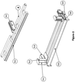
- Figure 2
- The perspective view of pressure group, thrust group, perspective and tilting group.
- Figure 3
- The perspective view of form group and miter group.
- Figure 4
- The perspective view of the bending unit.
- Figure 5
- The perspective view of carrier grill
- Figure 6
- The perspective view of inner mold thrust group
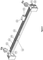
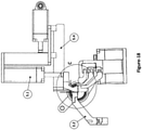
- Figure 7
- The perspective view of main frame group
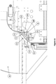
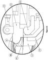
- Figure 8
- The perspective view of the system.
- Figure 9
- It is a sectioned view of elbow bracket.
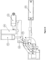
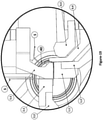
- Figure 10
- The side view of the system.
- Figure 11
- Side view of the starting position
- Figure 12
- Perspective view of the first position
- Figure 13
- Side view of the first position
- Figure 14
- Look of the A view.
- Figure 15
- Side view of second position
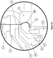
- Figure 16
- Look of the B view.
- Figure 17
- Perspective view of the second position
- Figure 18
- Side view of the third position
- Figure 19
- Look of the C view.
- Figure 20
- Side view of the fourth position.
- Figure 21
- Look of the D view.
- Figure 22
- Perspective view of the fourth position.
- Figure 23
- Side view of the fifth position.
- Figure 24
- Look of the E view.
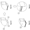
- Figure 25
- The appearance of the tear opened for the rolled sheet metal at the square canal corner.
- Figure 26
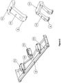
- Perfective view of square canal with two flanges formed at the edges.
- Figure 27
- Detailed view of the created flange
- Figure 28
- Perspective view of flanged square canal.
- Figure 29
- Appearance of the sheet metal metal with a folded tear at the elbow bracket canal corner.
- Figure 30
- Perspective view of an elbow bracket channel with two flanges formed
- Figure 31
- It is a detailed view of the created flange.
- Figure 32
- Perspective view of created elbow bracket
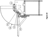
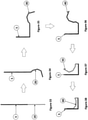
- Figure 33
- It is the appearance of the starting position
- Figure 34
- Appearance of the first position.
- Figure 35
- Apperarance of the second position.
- Figure 36
- View of the third position.
- Figure 37
- View of the fourth position.
- Figure 38
- View of the flange created.
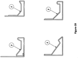
- Figure 39
- View of flange sections of different construction
- The figures to aid in the understanding of this invention are numbered as indicated in the accompanying figure and are given below along with their names.
-
- 1.
- Pressure Group
1.1 Pressure plate
1.2 Foot - 2.
- Thrust Group
2.1 Thrust plate
2.2 Thrust foot - 3.
- 3. Standing and tilting Group
3.1 Tilt piston
3.2 Standing piston
3.3 Joint
3.4 Standing and tilting press - 4.
- Forming Group
4.1 Thread form
4.2 Thrust piston - 5.
- Miter Group
5.1 Pressure piston
5.2 Connection bracet
5.3 Miter thrust piston
5.4 Side guide
5.5 Steep pressure plate
5.6 Piston rod - 6.
- Bending unit
6.1 Forming thrust guide
6.2 Standing form thrust guide
6.3 Main connection
6.4 Aiding stand
6.5 Form
6.6 Side plate
6.7 Forming thrust piston
6.8 Standing form piston
6.9 Pressure canal - 7.
- Carrier grid
7.1 Grid standing piston
7.2 Carriage connection plate
7.3 Rail connection plate - 8.
- Inner Mold Thust Group
8.1 Inner Mold
8.2 Thrusting horizontal piston - 9.
- Main Frame Group
9.1 Recline Group Canal
9.2 Stainonery guide
9.3 Roller /Bearings
9.4 Bending piston
9.5 Side plate - 10.
- Starting Position
- 20.
- First Position
- 30.
- Second Position
- 40.
- Third Position
- 50.
- Fourth Position
- 60.
- Flange formation of flange
- B.
- Bending tear
- D.
- Elbow bracket
- F.
- Flange
- K.
- Square Canal
- S.
- Sheet Metal
- The invention is based on the fact of, the positioning of the elbow bracket(D) and / or the square canal (K) on the carrier grid 7, which is finished with the corrugated bend B, is completed by the positioning of the elbow D and / or the square canal (K) sheet metal metal (S) in the starting position; (10) is pressed between the sheet metal metal (S), the form (6.5) and the thread form (4.1) brought into the starting position (10) by pressing with the help of the pressure group (1), the thrust group (2) and the miter group to the first position (20), bringing the sheet metal (S) bending pistion (9.4) and the pressure plate (1.1) being turn in 90 degree direction to bringing to the second position (30), by bringing the sheet metal(S) to second position (30) to be pressed aided with steep pressure plate (5.5) and aiding stand (6.4) bringing to third position (40), by bringing the sheet metal (S) to third position (40) with the aid of inner mold (8.1) and standing and tilting press (3.4) bringing to fourth position (50) and by bringing the sheet metal (S) to be press by tilt piston (3.1) and joint (3.3) to fit to square canal (K) and/or the mouth of elbow joint (D) to flange formation of flange (60). (
Fig. 11 ,Fig.14 ,Fig.16 ,Fig.19 ,Fig 21 ,Fig. 24 ) - The subject invention, together with the product, the flange is formed (60) at the mouth of the square channel (K) and / or the elbow joint (D). The invention includes forming a sheet metal flange (60) between two bending tears (B).
- Bringing it to the starting position (10); sheet metal (S) with bending tears (B) opened at its corners fitting to the square shaped elbow bracket (D) or to the square canal (K) to be placed on the carrier grid (7), at the same time, creating pressure to sheet metal (S) with pressure plate (1.1) in the pressure group (1) which is on main frame group (9) along with conjuction foot (1.2) and thrust foot (2.2) on thrusting group (2), to compress the (S) with other miter group (5) elements of steep pressure plate (5.5) and foot (1.2) and trust foot (2.2) and standing pressure plate (5.5) are other steps of the procedure. (
Fig.10 ,Fig.11 ) - To create the first position (20) includes the following steps of, moving the form (6.5) on top of the form thrusting guide (6.1) by forward in bending unit (6.7) in the bending unit (6), at the same time to moving the tread form (4.1) forward by the thrust piston (4.2) in the form group (4) and to press the sheet metal (S) in there by moving the tread form (4.1) towards eachother. (
Fig.12 ,Fig.14 ). In forming thefirst position 20, the number of edges can be changed depending on the surface shape of the female form (4.1) (Fig. 14 ). In forming the first position (20), the number of edges can be changed depending on the surface shape of the thread form (4.1) (Fig.14 ). - Second position (30) includes the following steps of, after formation of the first position (20) form group (4) retractes and bending piston (9.4) in the main together with the presser plate (1.1) in the main frame group (9) rotate the bending unit (6) on the presser foot (1) by 90 degrees, at the time of rotating thurst foot (2.2) along with steep pressure plate (5.5) supporting the 90 degree bending of the sheet metal (S) creating the third position. (
Fig. 16 ) - Fourth position, (50) follows the formation of third position (40) including the following steps; with the aid of the miter group (5) unit aid standing (6.4) retracts and instead standing horizontal piston (8.2) moves along in two pieced inner (8.1) inner mold thrust group (3) along with standing and tilting press (3.4), with the movement coming from standing piston (3.2) moves the sheet metal (S) in to the inner mold (8.1) to be pressed. (
Fig. 19 ) - Forming a flange (60) includes the following steps; the forward movement of the tilting piston (3.1) following the formation of the fourth position (50) causes the tilting movement of the joint (3.3) simultaneously with the tilting piston (3.1)" the movement of the tilting piston (3.1) with the standing and tilting press (3.4) involves pressing, machining steps on one side of sheet metal (S), square channel (K) and/or elbow bracket (D). (
Fig. 21 ) - The invention provides for the formation of an edge flange (60) opposite the square canal (K) and/or the elbow bracket (D) in the second stage after forming the flange (60) on one side of the finished square channel (K) and/or forming a third edge flange (60) in a third step (60) and forming a flange (60) at the edge of the final square canal (K) and / or elbow bracket (D). In forming the flange (60), the number of edges can change depending on the surface shape of the inner mold (8.1) (
Fig. 27, Fig.28 ,Fig.31, Fig.32 ). The invention is characterized in that it comprises a recline group canal (9.1) on which a stationary recline canals (9.1), four parallel stainonery guides (9.2), two parallel rollers (9.3), two bending pistons (9.4) on the side edges and side plates of main frame group (9) is associated with the second and the third stationary guide (9.2) in relation to the base group (9) by being connected to the main chasis base group (9) in such a way that the base group (9) is positioned more than once, (5) is associated with the first and fourth fixed slides (9.2) so that the form group (4) positioned in the main frame group (9) is connected to the second and fourth fixed slides (9.2) is also associated with the bearings (9.3) so that the bending unit (6) positioned in the main frame group (9) is connected to the pressure channel (6.9) on the bending unit (6) the inner presser foot (1.2) fixed to the upper surface of the side plate (9.5) with the carrier grid (7) positioned in the main frame group (9) and associated with the side plates (9.5) and with connection of thrusting horizontal piston (8.2) and inner mold thrust group (8). (Fig.1 ,Fig.7 ). - The invention has a pressure group (1) consisting of a pressure plate (1.1) positioned on the upper surface of the foot (1.2) and the foot (1.2) on the lower part (
Figure 2 ). The invention has a thrust group (2) which is composed of two opposing thrust feet (2.2) and a thrust plate (2.1) positioned on the upper surface of the thrust feet (2.2). (Fig.2 ) - According to the invention, the standing and tilting group (3); (3.3) positioned between the standing and tilting presser (3.4) and two tilting pistons (3.1) connected to the standing and tilting press (3.4) consists of the standing piston (3.2) in the part (
Fig. 2 ). - The invention has a form group (4) with a thread form (4.1) at the front and a thrust piston (4.2) at the rear end (
Fig.3 ). The miter group (5) provided in the subject of the invention; connection bracket (5.2) associated with the pressure pistons (5.1), a miter thrust piston (5.3) associated with the steep pressure plate (5.5), one or more pushing pistons (5.4) and the piston rod (5.6) positioned at the front of the compression pistons (5.1) (Fig.3 ). - The bending unit (6) provided in the subject of the invention; located on the side portions of the main connection (6.3), a form thrusting piston (6.7) and an standing form piston (6.8) which are positioned on the outer side portions of the side plates (6.6)), as well as the auxiliary pressure canal(6.9) positioned at the rear of the main connection (6.3), the form thrust guide (6.1) and the standing form thrust guide (6.2), is related to the standing aid (6.4) (
Fig.4 ). - The carrier grid (7) in the present invention comprises; the rail connection plate (7.3) located on the rear side of lower part of the grid and frame consists of fixed to the car connection rail (7.2) and the grid lifting piston (7.1) associated with the car connection rail (7.2). (
Fig.5 ). - The invention has an inner mold thrust group (8) consisting of an inner mold (8.1) and a thrusting horizontal piston (8.2) as two parts (Figure-1, Figure-6). The invention includes a standing and tilting press (3.4) which allows the sheet metal (S) to provide the desired shape (
Fig.2 ). The invention includes the thrust piston (4.2) which allows the form group (4) to move back and forth (Fig.3 ). - The invention includes a miter thrust piston (5.3) which moves the set square group (5) back and forth (
Figure 3 ). In the present invention, there is a forming thrust guide (6.1) which moves the form (6.5) back and forth (Figure-4). The invention includes a form thrust piston (6.7) which reciprocates the standing form thrust guide. (6.2) (Fig.4 ). - The inventive parts essentially consist of; standing and tilting group (3), form group (4), miter group (5), bending unit (6), carrier grid (7), inner mold thrust group (8) ) and main frame group (9) (
Fig.1 ). - The present invention comprises with a pressure group (1) which consist of two parts (
Figure 2 ). These parts are the pressure plate (1.1) and the foot (1.2) (Fig.2 ). In the present invention, the thrust group (2) consists of two parts (Figure-2). These sections consist of a thrust plate (2.1) and a thrust foot (2.2) (Figure-2). In the present invention, the standing and tilting group (3) consists of four parts (Fig.2 ). These sections consist of a tilt piston (3.1), a standing piston (3.2), a joint (3.3) and a standing and tilting press (3.4) (Fig. 2 ). - The present invention comprises the form group (4) which comprises two parts (
Fig 3 ). These parts are thread form (4.1) and thrust piston (4.2) (Fig.3 ). The miters group (5) in the present invention consists of six parts (Figure-3). These sections consist of a pressure piston (5.1), a connecting bracket (5.2), a thrust piston (5.3), a side guide (5.4), a steep pressure plate (5.5) and a piston rod (5.6). (Fig.3 ) - The present invention comprises the bending unit (6) which includes nine parts (
Fig.4 ). These parts can be used to form the form piston (6.1), the form thruster guide (6.2), the main connection (6.3), the aiding stand (6.4), the form (6.5), the side plate (6.6) and the form thrust piston (6.8) and pressure canal (6.9). (Fig.4 ). The carrier grid (7) in the present invention comprises three parts (Figure 5 ). These are the grid lift piston (7.1), the carriage connection rail (7.2) and the rail connection plate (7.3) (Fig.5 ). - The present invention comprises, the inner mold thrust group (8) which consists of two parts (
Fig.6 ). These are the inner mold (8.1) and the thrusting horizontal piston (8.2) (Fig.6 ). The main frame (9) in the present invention consists of five parts (Fig.7 ). These sections consist of the canal (9.1), stationary guide (9.2), roller (9.3), bending piston (9.4) and side plate (9.5). (Fig.7 ) - The assembly of the product of the invention is as follows; thrust group units (2) are positioned so as to be more than one side by side in relation to the canal (9.1) on the main frame group (9) (
Fig.1 ,Fig.7 ). The miter group (5) is positioned relative to the second and third stainonary guide (9.2) on the main frame (9) (Fig.1 ,Fig.7 ) - The miter group (5) is positioned relative to the second and third stainonary guide (9.2) on the main frame (9). (
Fig.1 ,Fig.3 ). Form group (4) is located between the first and fourth stainonary guide (9.2) (Fig.1 ,Fig.3 ). Between the second and fourth stationary guide, (9.2) standing and tilting group (3) takes place. (Fig.1 ,Fig.2 ) The bending unit (6) is associated with the rollers (9.3) on the main frame (9) (Fig.1 ,Fig.4 ). The pressure group (1) is positioned in such a way that there is more than one side by side in the pressure canal (6.9) on the bending unit (6) (Fig.1 ,Fig.4 ). The supporting plate (9) on the main frame (9) is positioned with the supporting grid (7) (Fig.1 ,Fig. 5 , andFig.7 ). The inner plate is fixed to the inner thrust gauge (8) by the pushing horizontal piston (8.2) on the upper surface of the side plate (9.5) (Fig.1 ,Fig.6 , andFig.7 ). - The bending unit (6) is associated with the bearings (9.3) on the main frame (9) (
Fig. 1 ,Fig. 4 ). The pressure group (1) is positioned in such a way that there is more than one side by side in the pressure canal (6.9) on the bending unit (6) (Fig.1 ,Fig.4 ). The main chasis group (9) on the main frame (9) is positioned with the carrier grid (7) (Fig.1 ,Fig.5 , andFig.7 ). The inner plate is fixed to the inner thrust group (8) by the thrusting horizontal piston (8.2) on the upper surface of the side plate (9.5) (Fig.1 ,Fig. 6 , andFig.7 ). - The features of the present invention are as follows; Pressure group (1), in the initial position (10) bends the sheet metal (S) by 90 degrees (
Fig.16 ). The thrust group (2); helps to fix the position by clamping the bent sheet (S) in the initial position (10) while tightening it with the vertical steep pressure plate (5.5) in the miter group 5 (Fig.14 ). - Standing and Tilting Group (3); has 2 different duties. The first is to allow the sheet metal (S) to pass from the third position (40) to the fourth position (50) and the second is to make the transition from the fourth position (50) to the formation of the flange (60) position (
Fig. 19 ,Fig.21 ). - The standing and tilting group (3) allows the sheet metal (S) to be brought to the fourth position (50) from the third position (40) by the forward movement of the standing piston (3.2) positioned in the main frame (9) relative to the second and fourth stationary guide(9.2).(
Fig.21 ) The forward and backward movements of the tilting piston (3.1) are then angularly moved to allow the sheet metal (S) to transition from the fourth position (50) to the flange forming position (60) with the help of the vertical and tilting presser joint(3.3 ). (Fig 24 ) Thus the final stage of the desired flange (F) is finished and returned to the initial position for the operation of the next edge. - The Forming Group (4) is fixed to the main frame group (9) by being associated with the first and fourth stationary guides (9.2) and the thrust piston (4.2) is connected to the thread form piston (4.1) and the form thrust piston (6.1) to move from the starting position (10) to the first position (20) by pressing the sheet metal (S) between the thread form (4.1) and the form (6.5) (
Fig.4 ,Fig.14 ). After passing through the first position (20), the form group (4) returns to its initial position to move to the next position. - Miter group (5); duties are frame with two tasks. The first is to clamp the sheet (S) against the pressure plate (2.1) and the second is to support against the pressure plate (1.1). The bending unit (6); of the sheet metal (S) which is to be carried is placed at 90 degrees with the rotation of the group (1) on its axis. The second position (30) and the third position (40) provide the transition from the first position (20) to the second position (30) and the standing position (6.4) on the second position (30) (
Fig. 14 ,Fig. 16 ). - Carrier grid (7); to establish the bending process moves in up and down movement to eliminate the difference in heights at square canal (K)and the elbow bracket(D) with the aid of moving rollers. (
Fig. 9 ) Inner mold group thrust group (8); aids the sheet metal (S) to be pushed into the inner mold (8.1) to give its final shape and the standing and tilting group (3) in order to assist to forming the flange (60) (Fig. 24 ). - The inner mold thrust group (8); the thrust horizontal piston (8.2) fixed on the side plate (9.5) applies pressure to the sheet metal (S) in the inner mold (8.1). The inner mold thrustgroup (8) helps the standing and tilting group (3) fulfills its task (
Fig.24 ). In this process the miter group (5) comes to its first position by canceling the last position. The production method of the invention product is as follows; Elbow bracket (D) and/or Square canal (K) which have bending tear on the corners are placed on one of the four sides of the carrier grid (7) (Fig. 11 ). At this time, the presser foot (1) on the main frame (9) applies pressure to the sheet metal (S) with the thrust foot (2.2) associated with the pressure group foot (1.2) and the thrust plate (2.1) in the Thurst group (2) (Fig. 11 ) On the other side, the sheet metal (S) is applied pressure by the steep presser plate (5.5) in the miter group (5) (Figure 11 ). Thus, the starting position (10) is formed by pressing the sheet metal (S) with the help of the pressure foot (1.2), the thrust foot (2.2) and the steep pressure plate (5.5) (Fig. 11 ). - After the initial position (10) is formed, the bending unit form (6.5) on the form thrusting guide (6.1) in the bending unit (6) is moved forward by the thrusting piston (6.7) (
Fig. 14 ). The thread form (4.1) in the form group (4) is moved forward by the thrust piston (4.2) in the same way as the form (6.5). (Figure-14). Thus, sheet (S) remains between form (6.5) and female form (4.1) (Figure-14). After the form (6.5) and the thread form (4.1) are moved together, the resulting sheet metal (S) is pressed. (Fig. 14 ). As a result of this operation, the first position (20) is formed (Fig. 14 ). - After forming the first position (20), the form group (4) is retracted and returns to its initial position (
Fig. 16 ). The bending piston (9.4) on the main frame (9) rotates the bending unit (6) 90 degrees together with the bending plate (1.1) on the press group (1) (Fig. 16 ). During rotation, the standing plate (5.5) with the thrust foot (2.2) supports 90 degree bend of the sheet metal (S) (Fig. 16 ). Thus, the sheet metal (S) is brought to the second position (30) (Fig. 16 ). - After the third position (40) is formed, the aiding stand (6.4) and the miter group (5) are retracted (
Fig. 19 ). The inner mold (8.1), which is in two parts by the movement taken by the thrusting horizontal piston (8.2), is replaced with the pulled miter group (5) (Figure 19 ). The standing tilting press (3.4) on the standing and tilting group (3) provides the pressing of the inner mold (8.1) of the sheet metal (S) with the movement taken from the vertical piston (3.2). (Fig. 19 ) Thus, the sheet metal (S) is brought to the fourth position (50) (Fig.21 ). - After forming the fourth position (50), the tilting piston (3.1) moves forward (
Fig. 24 ). Simultaneously with the tilting piston (3.1), the joint (3.3) makes a rotational movement and as a result of the movements of the tilting piston (3.1) and the elbow joint (3.3), the vertical and tilting presses (3.4) (D) (Figure-21). Consequently of the pressing, the flange is formed (60) (Fig. 24 ).
Claims (13)
- - A method of forming a flange on a ventilation canal edge using a machine according to any of claims 7-14, the method comprising the following process steps:- positioning of a square elbow bracket (D) and / or a square canal (K) on the carrier grid (7), the elbow bracket (D) and/or the square canal (K) comprising bend tears (B) at its corners,- moving the elbow bracket (D) which positioned on the carrier grid (7) and/or the sheet metal (S) at the mouth of the square canal (K), to the starting position (10) by compressing it with the help of pressure group (1), thrust group (2) and miter group (5),- moving the sheet metal (S) brought into the starting position (10) into the first position (20) by pressing between the form (6.5) and the thread form (4.1)- moving the sheet metal (S) brought into the first position (20) into the second position (30) by turning it 90 degrees together with the bending piston (9.4) and the press plate (1.1)- moving the sheet metal (S) brought into the second position (30) into the third position (40) by being pressed between the steep pressure plate (5.5) and the aiding stand (6.4)- moving the sheet metal (S) that brought into the third position (40) into the fourth position (50) by the inner mold (8.1) and the standing and tilting press (3.4)- forming a one piece flange (60) at the mouth of the square canal (K) and / or the elbow bracket (D) by pressing the sheet metal (S) brought into the fourth position (50) by the tilt piston (3.1) and the joint (3.3).
- A method of forming a flange on a ventilation canal edge according to claim 1 characterized by comprising; forming a flange (60) from the sheet metal remaining between two bend tears (B).
- A method of forming a flange on a ventilation canal edge according to claim 1 characterized by comprising; the sheet metal (S) being pressed with the help of the pressure foot (1.2), the thrust foot (2.2) and the steep pressure plate (5.5) at the starting position (10)
- A method of forming a flange on a ventilation canal edge according to claim 1 characterized by comprising; the sheet metal (S); being pressed into the first position (20) between the bending form (6.5) moving forward by the forming thrust piston (6.7) and the thread form (4.1) moving forward by the thrust piston (4.2).
- A method of forming a flange on a ventilation canal edge according to claim 1 characterized by comprising; by the presence of the thrust foot (2.2) supporting the 90 degree bending of the sheet metal (S) and the steep pressure plate (5.5).
- A method of forming a flange on a ventilation canal edge according to claim 1 characterized by comprising;- moving back to the original position of aiding stand (6.4) and miter group (5), after the third position (40) is formed and- moving back to the fourth position (50) of the sheet metal (S) by pressing the inner mold (8.1) in two parts coming from the movement of the thrusting horizontal piston (8.2) instead of the drawn miter group (5) and the standing and tilting press (3.4) moved by the standing piston (3.2).
- - A machine for forming a flange on the edge of a ventilation canal, characterized by comprising;- a main frame group (9) on which there is a recline group canal (9.1), four fixed stationary guide (9.2) parallel to each other, two bearings/ rullers (9.3) parallel to each other, two bending pistons (9.4) on the side edges and side plates (9.5) on the sides,- a thrust group (2) positioned so as to be more than one, side by side in the main frame group (9) in relation to the reclining group canal (9.1)- a miter group (5) positioned in the main frame group (9) by associating it between the second and third stationary guide (9.2), the miter group (5) comprising a step pressure plate (5.5) at the front of the miter group (5),- a forming group (4) positioned in the main frame group (9) by associating it between the first and fourth stationary guide (9.2), the forming group (4) comprising a thread form (4.1) at the front of the forming group (4),- a standing and tilting group (3) positioned to the main frame group (9) by associating between the second and fourth stationary guide (9.2), the standing and tilting group comprising: a standing and tilting press (3.4) positioned at the front of the standing and tilting group (3), two tilting pistons associated with the standing and tilting press (3.4), and a joint (3.3) positioned between each tilting piston (3.1) and the standing and tilting press (3.4),- a bending unit (6) positioned in the main frame group (9) by being connected to the roller/bearings (9.3), the bending group (6) comprising an aiding stand (6.4) associated with a standing form thrust guide (6.2), and a form (6.5) associated with a form thrust guide (6.1),- more than one pressure group (1) positioned side by side on the pressure canal (6.9) of the bending unit (6, each pressure group (1) being formed on its lower part with a pressure foot (1.2) and a pressure plate (1.1) positioned on the upper surface of the foot (1.2),- a carrier grid (7) positioned in the main frame group (9) in relation to the side plates (9.5) and- an inner mold thrust group (8) fixed to the upper surface of the side plate (9.5) via a thrusting horizontal piston (8.2), the inner mold thrust group (8) comprising an inner mold (8.1).
- - A machine according to claim 7, the standing and tilting group (3) further comprises a standing piston (3.2).
- - A machine according to claim 7, the miter group (5) further comprising:- one pressure piston (5.1) located in the side parts,- the connecting bracket (5.2) associated with the pressure pistons (5.1)- the miter thrust piston (5.3) associated with the connecting brackets (5.2) the side guides (5.4) on the side outer edges and- a piston rod (5.6) positioned in front of the pressure pistons (5.1).
- - A machine according to claim 7, the bending group (6) further comprising:- a main connection (6.3),- one side plate (6.6) positioned on the sides of the main connection (6.3),- a form thrusting piston (6.7) and a standing form piston (6.8), which are positioned on the outer side portions of the side plates (6.6)- a pressure canal (6.9), the form thrust guide (6.1) and the standing form thrust guide (6.2) positioned at the rear of the main connection (6.3).
- - A machine according to claim 7, the carrier grid (7) comprising:- the carriage connection plate (7.2) positioned on the rear side lower part of a grid frame,- the rail connection plate (7.3) fixed to the carriage connection plate (7.2) and characterized by the fact that it is constituted by the grid standing piston (7.1) associated with the carriage connection plate (7.2).
- - A machine for forming a ventilation canal flange according to claim 7, the forming group (4) comprising a thread piston (4.2) for moving the forming group (4) back and forth.
- - A machine for forming a ventilation canal flange according to claim 7, the miter group (5) comprising a miter thrust piston (5.3) which moves the miter group (5) back and forth.
Applications Claiming Priority (2)
| Application Number | Priority Date | Filing Date | Title |
|---|---|---|---|
| TR2017/03222A TR201703222A2 (en) | 2017-03-02 | 2017-03-02 | VENTILATION CHANNEL EDGE FLANGE METHOD AND A MACHINE USED FOR THIS METHOD |
| PCT/TR2018/000014 WO2018236314A2 (en) | 2017-03-02 | 2018-02-27 | Method of building flange in ventilation canal edge and a machine used for this |
Publications (3)
| Publication Number | Publication Date |
|---|---|
| EP3589430A2 EP3589430A2 (en) | 2020-01-08 |
| EP3589430A4 EP3589430A4 (en) | 2020-11-18 |
| EP3589430B1 true EP3589430B1 (en) | 2022-02-16 |
Family
ID=64736070
Family Applications (1)
| Application Number | Title | Priority Date | Filing Date |
|---|---|---|---|
| EP18819861.8A Active EP3589430B1 (en) | 2017-03-02 | 2018-02-27 | Method of building flange in ventilation canal edge and a machine used for this |
Country Status (3)
| Country | Link |
|---|---|
| EP (1) | EP3589430B1 (en) |
| TR (1) | TR201703222A2 (en) |
| WO (1) | WO2018236314A2 (en) |
Families Citing this family (3)
| Publication number | Priority date | Publication date | Assignee | Title |
|---|---|---|---|---|
| CN110508656A (en) * | 2019-08-22 | 2019-11-29 | 华达汽车科技股份有限公司 | A kind of hemmer with heating function |
| IT202100001517A1 (en) * | 2021-01-26 | 2022-07-26 | Air Prom Srl | "PROCESS OF MANUFACTURING AN VENTILATION DUCT OR THE LIKE, AND VENTILATION DUCT SO PRODUCED" |
| CN116748808B (en) * | 2023-06-16 | 2024-02-23 | 广州市全风机电设备有限公司 | Fireproof air duct processing method |
Family Cites Families (10)
| Publication number | Priority date | Publication date | Assignee | Title |
|---|---|---|---|---|
| DE3816688A1 (en) * | 1988-05-17 | 1989-11-30 | Rolf Peter Smitka | Flange connection for an air duct consisting of sheet metal, and process for producing such a flange connection |
| CH688646A5 (en) * | 1994-02-22 | 1997-12-31 | Remo Trunz | Apparatus for forming profiled flanges |
| US5927135A (en) * | 1996-09-28 | 1999-07-27 | Reinhardt Maschinenbau Gmbh | Bending machine |
| ES2190298B1 (en) * | 2000-01-31 | 2004-10-16 | Goiti, S.Coop | METAL SHEET FOLDING MACHINE. |
| JP3935909B2 (en) * | 2002-10-22 | 2007-06-27 | 株式会社大林組 | Corner pieceless duct, method of manufacturing the same, and screw forming machine |
| GB2457414B (en) * | 2006-12-08 | 2011-03-30 | Jeffrey Allen Hermanson | Rectangular/square spiral ducting systems with flange connectors |
| US9212770B2 (en) * | 2007-07-18 | 2015-12-15 | RAM Developing, LLC | Method and apparatus for attaching flange portions to ducts |
| US8276425B2 (en) * | 2007-10-02 | 2012-10-02 | Mestek Machinery, Inc. | Ductmaking apparatus |
| CN101634384B (en) * | 2009-08-19 | 2011-04-06 | 厦门高特高新材料有限公司 | Metal-plastic composite air duct flange and manufacturing method thereof |
| US10317000B2 (en) * | 2015-02-17 | 2019-06-11 | Shinfuji Kuuchou Co., Ltd. | Duct flange structure, and manufacturing method for the same |
-
2017
- 2017-03-02 TR TR2017/03222A patent/TR201703222A2/en unknown
-
2018
- 2018-02-27 EP EP18819861.8A patent/EP3589430B1/en active Active
- 2018-02-27 WO PCT/TR2018/000014 patent/WO2018236314A2/en unknown
Also Published As
| Publication number | Publication date |
|---|---|
| WO2018236314A2 (en) | 2018-12-27 |
| EP3589430A2 (en) | 2020-01-08 |
| WO2018236314A3 (en) | 2019-03-07 |
| TR201703222A2 (en) | 2017-07-21 |
| EP3589430A4 (en) | 2020-11-18 |
Similar Documents
| Publication | Publication Date | Title |
|---|---|---|
| EP3589430B1 (en) | Method of building flange in ventilation canal edge and a machine used for this | |
| KR930011517B1 (en) | Apparatus for manufacturing welded steel pipe | |
| US20010054822A1 (en) | Spin forming a tubular workpiece to form a radial flange on a tubular flange and a bead or thick rim on the radial flange | |
| CN108973507B (en) | Construction robot of environmental protection wall decorations | |
| CA1056706A (en) | Method and apparatus for reforming round ducts into rectangular ducts | |
| US5657922A (en) | Machine and process for forming tapered or cylindrical utility poles from flat sheet metal | |
| CN113059059A (en) | Automatic processing machine for metal plate forming of metal cabinet body and metal plate processing method | |
| CN205519136U (en) | On press formula flattening device | |
| CN113182400A (en) | Automatic processing machine and method for producing metal pipe elbow | |
| JP2010137242A (en) | Device for forming reinforcing rib on metal plate | |
| CN110614331B (en) | Bending mechanism | |
| CN113910322A (en) | Cutting device based on geogrid | |
| JP6452157B2 (en) | Framework material manufacturing method and framework material manufacturing apparatus | |
| CN214813909U (en) | Flanging machine of round tube type air pipe | |
| CN212349973U (en) | Intelligent bending machine | |
| JP2514615B2 (en) | Continuous production facility for digits | |
| CN210966450U (en) | Circumferential weld trimmer based on fire extinguisher barrel processing | |
| JP2017075502A5 (en) | ||
| RU188709U1 (en) | SMITH MACHINE | |
| CN217289968U (en) | Rolling machine is used in processing of circular arc type aluminum alloy template | |
| RU20267U1 (en) | PIPE BENDING MACHINE | |
| JPS62156025A (en) | Production of curving plate for building and its production device | |
| CN216632172U (en) | Circular metalwork turn-up equipment | |
| CN213856477U (en) | Adjustable pipe bending machine for student desk and chair production | |
| CN217798272U (en) | Bending machine device for processing large-diameter pipeline |
Legal Events
| Date | Code | Title | Description |
|---|---|---|---|
| STAA | Information on the status of an ep patent application or granted ep patent |
Free format text: STATUS: THE INTERNATIONAL PUBLICATION HAS BEEN MADE |
|
| PUAI | Public reference made under article 153(3) epc to a published international application that has entered the european phase |
Free format text: ORIGINAL CODE: 0009012 |
|
| STAA | Information on the status of an ep patent application or granted ep patent |
Free format text: STATUS: REQUEST FOR EXAMINATION WAS MADE |
|
| 17P | Request for examination filed |
Effective date: 20191001 |
|
| AK | Designated contracting states |
Kind code of ref document: A2 Designated state(s): AL AT BE BG CH CY CZ DE DK EE ES FI FR GB GR HR HU IE IS IT LI LT LU LV MC MK MT NL NO PL PT RO RS SE SI SK SM TR |
|
| AX | Request for extension of the european patent |
Extension state: BA ME |
|
| DAV | Request for validation of the european patent (deleted) | ||
| DAX | Request for extension of the european patent (deleted) | ||
| REG | Reference to a national code |
Ref country code: DE Ref legal event code: R079 Ref document number: 602018030996 Country of ref document: DE Free format text: PREVIOUS MAIN CLASS: B21D0005010000 Ipc: B21D0005040000 |
|
| A4 | Supplementary search report drawn up and despatched |
Effective date: 20201019 |
|
| RIC1 | Information provided on ipc code assigned before grant |
Ipc: F24F 13/02 20060101ALI20201013BHEP Ipc: B21D 5/04 20060101AFI20201013BHEP Ipc: B21D 22/02 20060101ALI20201013BHEP Ipc: B21D 19/08 20060101ALI20201013BHEP |
|
| STAA | Information on the status of an ep patent application or granted ep patent |
Free format text: STATUS: EXAMINATION IS IN PROGRESS |
|
| 17Q | First examination report despatched |
Effective date: 20210330 |
|
| GRAP | Despatch of communication of intention to grant a patent |
Free format text: ORIGINAL CODE: EPIDOSNIGR1 |
|
| STAA | Information on the status of an ep patent application or granted ep patent |
Free format text: STATUS: GRANT OF PATENT IS INTENDED |
|
| INTG | Intention to grant announced |
Effective date: 20210906 |
|
| GRAS | Grant fee paid |
Free format text: ORIGINAL CODE: EPIDOSNIGR3 |
|
| GRAA | (expected) grant |
Free format text: ORIGINAL CODE: 0009210 |
|
| STAA | Information on the status of an ep patent application or granted ep patent |
Free format text: STATUS: THE PATENT HAS BEEN GRANTED |
|
| AK | Designated contracting states |
Kind code of ref document: B1 Designated state(s): AL AT BE BG CH CY CZ DE DK EE ES FI FR GB GR HR HU IE IS IT LI LT LU LV MC MK MT NL NO PL PT RO RS SE SI SK SM TR |
|
| REG | Reference to a national code |
Ref country code: GB Ref legal event code: FG4D |
|
| REG | Reference to a national code |
Ref country code: CH Ref legal event code: EP |
|
| REG | Reference to a national code |
Ref country code: DE Ref legal event code: R096 Ref document number: 602018030996 Country of ref document: DE |
|
| REG | Reference to a national code |
Ref country code: AT Ref legal event code: REF Ref document number: 1468572 Country of ref document: AT Kind code of ref document: T Effective date: 20220315 |
|
| REG | Reference to a national code |
Ref country code: IE Ref legal event code: FG4D |
|
| REG | Reference to a national code |
Ref country code: LT Ref legal event code: MG9D |
|
| REG | Reference to a national code |
Ref country code: NL Ref legal event code: MP Effective date: 20220216 |
|
| REG | Reference to a national code |
Ref country code: AT Ref legal event code: MK05 Ref document number: 1468572 Country of ref document: AT Kind code of ref document: T Effective date: 20220216 |
|
| PG25 | Lapsed in a contracting state [announced via postgrant information from national office to epo] |
Ref country code: SE Free format text: LAPSE BECAUSE OF FAILURE TO SUBMIT A TRANSLATION OF THE DESCRIPTION OR TO PAY THE FEE WITHIN THE PRESCRIBED TIME-LIMIT Effective date: 20220216 Ref country code: RS Free format text: LAPSE BECAUSE OF FAILURE TO SUBMIT A TRANSLATION OF THE DESCRIPTION OR TO PAY THE FEE WITHIN THE PRESCRIBED TIME-LIMIT Effective date: 20220216 Ref country code: PT Free format text: LAPSE BECAUSE OF FAILURE TO SUBMIT A TRANSLATION OF THE DESCRIPTION OR TO PAY THE FEE WITHIN THE PRESCRIBED TIME-LIMIT Effective date: 20220616 Ref country code: NO Free format text: LAPSE BECAUSE OF FAILURE TO SUBMIT A TRANSLATION OF THE DESCRIPTION OR TO PAY THE FEE WITHIN THE PRESCRIBED TIME-LIMIT Effective date: 20220516 Ref country code: NL Free format text: LAPSE BECAUSE OF FAILURE TO SUBMIT A TRANSLATION OF THE DESCRIPTION OR TO PAY THE FEE WITHIN THE PRESCRIBED TIME-LIMIT Effective date: 20220216 Ref country code: LT Free format text: LAPSE BECAUSE OF FAILURE TO SUBMIT A TRANSLATION OF THE DESCRIPTION OR TO PAY THE FEE WITHIN THE PRESCRIBED TIME-LIMIT Effective date: 20220216 Ref country code: HR Free format text: LAPSE BECAUSE OF FAILURE TO SUBMIT A TRANSLATION OF THE DESCRIPTION OR TO PAY THE FEE WITHIN THE PRESCRIBED TIME-LIMIT Effective date: 20220216 Ref country code: ES Free format text: LAPSE BECAUSE OF FAILURE TO SUBMIT A TRANSLATION OF THE DESCRIPTION OR TO PAY THE FEE WITHIN THE PRESCRIBED TIME-LIMIT Effective date: 20220216 Ref country code: BG Free format text: LAPSE BECAUSE OF FAILURE TO SUBMIT A TRANSLATION OF THE DESCRIPTION OR TO PAY THE FEE WITHIN THE PRESCRIBED TIME-LIMIT Effective date: 20220516 |
|
| PGFP | Annual fee paid to national office [announced via postgrant information from national office to epo] |
Ref country code: GB Payment date: 20220426 Year of fee payment: 5 Ref country code: FR Payment date: 20220407 Year of fee payment: 5 Ref country code: DE Payment date: 20220425 Year of fee payment: 5 |
|
| PG25 | Lapsed in a contracting state [announced via postgrant information from national office to epo] |
Ref country code: PL Free format text: LAPSE BECAUSE OF FAILURE TO SUBMIT A TRANSLATION OF THE DESCRIPTION OR TO PAY THE FEE WITHIN THE PRESCRIBED TIME-LIMIT Effective date: 20220216 Ref country code: LV Free format text: LAPSE BECAUSE OF FAILURE TO SUBMIT A TRANSLATION OF THE DESCRIPTION OR TO PAY THE FEE WITHIN THE PRESCRIBED TIME-LIMIT Effective date: 20220216 Ref country code: GR Free format text: LAPSE BECAUSE OF FAILURE TO SUBMIT A TRANSLATION OF THE DESCRIPTION OR TO PAY THE FEE WITHIN THE PRESCRIBED TIME-LIMIT Effective date: 20220517 Ref country code: FI Free format text: LAPSE BECAUSE OF FAILURE TO SUBMIT A TRANSLATION OF THE DESCRIPTION OR TO PAY THE FEE WITHIN THE PRESCRIBED TIME-LIMIT Effective date: 20220216 Ref country code: AT Free format text: LAPSE BECAUSE OF FAILURE TO SUBMIT A TRANSLATION OF THE DESCRIPTION OR TO PAY THE FEE WITHIN THE PRESCRIBED TIME-LIMIT Effective date: 20220216 |
|
| PG25 | Lapsed in a contracting state [announced via postgrant information from national office to epo] |
Ref country code: IS Free format text: LAPSE BECAUSE OF FAILURE TO SUBMIT A TRANSLATION OF THE DESCRIPTION OR TO PAY THE FEE WITHIN THE PRESCRIBED TIME-LIMIT Effective date: 20220617 |
|
| REG | Reference to a national code |
Ref country code: CH Ref legal event code: PL |
|
| REG | Reference to a national code |
Ref country code: BE Ref legal event code: MM Effective date: 20220228 |
|
| PG25 | Lapsed in a contracting state [announced via postgrant information from national office to epo] |
Ref country code: SM Free format text: LAPSE BECAUSE OF FAILURE TO SUBMIT A TRANSLATION OF THE DESCRIPTION OR TO PAY THE FEE WITHIN THE PRESCRIBED TIME-LIMIT Effective date: 20220216 Ref country code: SK Free format text: LAPSE BECAUSE OF FAILURE TO SUBMIT A TRANSLATION OF THE DESCRIPTION OR TO PAY THE FEE WITHIN THE PRESCRIBED TIME-LIMIT Effective date: 20220216 Ref country code: RO Free format text: LAPSE BECAUSE OF FAILURE TO SUBMIT A TRANSLATION OF THE DESCRIPTION OR TO PAY THE FEE WITHIN THE PRESCRIBED TIME-LIMIT Effective date: 20220216 Ref country code: LU Free format text: LAPSE BECAUSE OF NON-PAYMENT OF DUE FEES Effective date: 20220227 Ref country code: EE Free format text: LAPSE BECAUSE OF FAILURE TO SUBMIT A TRANSLATION OF THE DESCRIPTION OR TO PAY THE FEE WITHIN THE PRESCRIBED TIME-LIMIT Effective date: 20220216 Ref country code: DK Free format text: LAPSE BECAUSE OF FAILURE TO SUBMIT A TRANSLATION OF THE DESCRIPTION OR TO PAY THE FEE WITHIN THE PRESCRIBED TIME-LIMIT Effective date: 20220216 Ref country code: CZ Free format text: LAPSE BECAUSE OF FAILURE TO SUBMIT A TRANSLATION OF THE DESCRIPTION OR TO PAY THE FEE WITHIN THE PRESCRIBED TIME-LIMIT Effective date: 20220216 |
|
| REG | Reference to a national code |
Ref country code: DE Ref legal event code: R097 Ref document number: 602018030996 Country of ref document: DE |
|
| PG25 | Lapsed in a contracting state [announced via postgrant information from national office to epo] |
Ref country code: MC Free format text: LAPSE BECAUSE OF FAILURE TO SUBMIT A TRANSLATION OF THE DESCRIPTION OR TO PAY THE FEE WITHIN THE PRESCRIBED TIME-LIMIT Effective date: 20220216 Ref country code: AL Free format text: LAPSE BECAUSE OF FAILURE TO SUBMIT A TRANSLATION OF THE DESCRIPTION OR TO PAY THE FEE WITHIN THE PRESCRIBED TIME-LIMIT Effective date: 20220216 |
|
| PLBE | No opposition filed within time limit |
Free format text: ORIGINAL CODE: 0009261 |
|
| STAA | Information on the status of an ep patent application or granted ep patent |
Free format text: STATUS: NO OPPOSITION FILED WITHIN TIME LIMIT |
|
| 26N | No opposition filed |
Effective date: 20221117 |
|
| PG25 | Lapsed in a contracting state [announced via postgrant information from national office to epo] |
Ref country code: LI Free format text: LAPSE BECAUSE OF NON-PAYMENT OF DUE FEES Effective date: 20220228 Ref country code: IE Free format text: LAPSE BECAUSE OF NON-PAYMENT OF DUE FEES Effective date: 20220227 Ref country code: CH Free format text: LAPSE BECAUSE OF NON-PAYMENT OF DUE FEES Effective date: 20220228 |
|
| PG25 | Lapsed in a contracting state [announced via postgrant information from national office to epo] |
Ref country code: SI Free format text: LAPSE BECAUSE OF FAILURE TO SUBMIT A TRANSLATION OF THE DESCRIPTION OR TO PAY THE FEE WITHIN THE PRESCRIBED TIME-LIMIT Effective date: 20220216 Ref country code: BE Free format text: LAPSE BECAUSE OF NON-PAYMENT OF DUE FEES Effective date: 20220228 |
|
| PG25 | Lapsed in a contracting state [announced via postgrant information from national office to epo] |
Ref country code: IT Free format text: LAPSE BECAUSE OF FAILURE TO SUBMIT A TRANSLATION OF THE DESCRIPTION OR TO PAY THE FEE WITHIN THE PRESCRIBED TIME-LIMIT Effective date: 20220216 |
|
| REG | Reference to a national code |
Ref country code: DE Ref legal event code: R119 Ref document number: 602018030996 Country of ref document: DE |
|
| GBPC | Gb: european patent ceased through non-payment of renewal fee |
Effective date: 20230227 |
|
| PG25 | Lapsed in a contracting state [announced via postgrant information from national office to epo] |
Ref country code: GB Free format text: LAPSE BECAUSE OF NON-PAYMENT OF DUE FEES Effective date: 20230227 |
|
| PG25 | Lapsed in a contracting state [announced via postgrant information from national office to epo] |
Ref country code: GB Free format text: LAPSE BECAUSE OF NON-PAYMENT OF DUE FEES Effective date: 20230227 Ref country code: FR Free format text: LAPSE BECAUSE OF NON-PAYMENT OF DUE FEES Effective date: 20230228 Ref country code: DE Free format text: LAPSE BECAUSE OF NON-PAYMENT OF DUE FEES Effective date: 20230901 |