EP3588889B1 - Kanalidentifizierung in einem mimo-telekommunikationssystem - Google Patents
Kanalidentifizierung in einem mimo-telekommunikationssystem Download PDFInfo
- Publication number
- EP3588889B1 EP3588889B1 EP19191548.7A EP19191548A EP3588889B1 EP 3588889 B1 EP3588889 B1 EP 3588889B1 EP 19191548 A EP19191548 A EP 19191548A EP 3588889 B1 EP3588889 B1 EP 3588889B1
- Authority
- EP
- European Patent Office
- Prior art keywords
- signals
- cell
- specific reference
- signal
- downlink
- Prior art date
- Legal status (The legal status is an assumption and is not a legal conclusion. Google has not performed a legal analysis and makes no representation as to the accuracy of the status listed.)
- Active
Links
- 238000000034 method Methods 0.000 claims description 16
- 238000005259 measurement Methods 0.000 claims description 13
- 238000012545 processing Methods 0.000 claims description 13
- 125000004122 cyclic group Chemical group 0.000 claims description 11
- 238000005070 sampling Methods 0.000 claims description 7
- 230000000875 corresponding effect Effects 0.000 description 11
- 108010076504 Protein Sorting Signals Proteins 0.000 description 6
- 238000013507 mapping Methods 0.000 description 6
- PCHJSUWPFVWCPO-UHFFFAOYSA-N gold Chemical group [Au] PCHJSUWPFVWCPO-UHFFFAOYSA-N 0.000 description 5
- 238000010586 diagram Methods 0.000 description 4
- 230000001360 synchronised effect Effects 0.000 description 4
- 230000005540 biological transmission Effects 0.000 description 3
- 238000004422 calculation algorithm Methods 0.000 description 3
- 238000004891 communication Methods 0.000 description 3
- 230000006870 function Effects 0.000 description 3
- 238000004088 simulation Methods 0.000 description 3
- 230000008878 coupling Effects 0.000 description 2
- 238000010168 coupling process Methods 0.000 description 2
- 238000005859 coupling reaction Methods 0.000 description 2
- 238000009434 installation Methods 0.000 description 2
- 238000005311 autocorrelation function Methods 0.000 description 1
- 230000010267 cellular communication Effects 0.000 description 1
- 238000006243 chemical reaction Methods 0.000 description 1
- 239000004020 conductor Substances 0.000 description 1
- 239000013256 coordination polymer Substances 0.000 description 1
- 238000012937 correction Methods 0.000 description 1
- 230000002596 correlated effect Effects 0.000 description 1
- 230000007774 longterm Effects 0.000 description 1
- 239000013307 optical fiber Substances 0.000 description 1
- 238000011084 recovery Methods 0.000 description 1
- 238000013515 script Methods 0.000 description 1
- 239000013598 vector Substances 0.000 description 1
Images


Classifications
-
- H—ELECTRICITY
- H04—ELECTRIC COMMUNICATION TECHNIQUE
- H04L—TRANSMISSION OF DIGITAL INFORMATION, e.g. TELEGRAPHIC COMMUNICATION
- H04L5/00—Arrangements affording multiple use of the transmission path
- H04L5/003—Arrangements for allocating sub-channels of the transmission path
- H04L5/0048—Allocation of pilot signals, i.e. of signals known to the receiver
- H04L5/005—Allocation of pilot signals, i.e. of signals known to the receiver of common pilots, i.e. pilots destined for multiple users or terminals
-
- H—ELECTRICITY
- H04—ELECTRIC COMMUNICATION TECHNIQUE
- H04B—TRANSMISSION
- H04B7/00—Radio transmission systems, i.e. using radiation field
- H04B7/02—Diversity systems; Multi-antenna system, i.e. transmission or reception using multiple antennas
- H04B7/04—Diversity systems; Multi-antenna system, i.e. transmission or reception using multiple antennas using two or more spaced independent antennas
- H04B7/0413—MIMO systems
-
- H—ELECTRICITY
- H04—ELECTRIC COMMUNICATION TECHNIQUE
- H04J—MULTIPLEX COMMUNICATION
- H04J11/00—Orthogonal multiplex systems, e.g. using WALSH codes
- H04J11/0069—Cell search, i.e. determining cell identity [cell-ID]
- H04J11/0079—Acquisition of downlink reference signals, e.g. detection of cell-ID
-
- H—ELECTRICITY
- H04—ELECTRIC COMMUNICATION TECHNIQUE
- H04L—TRANSMISSION OF DIGITAL INFORMATION, e.g. TELEGRAPHIC COMMUNICATION
- H04L27/00—Modulated-carrier systems
- H04L27/26—Systems using multi-frequency codes
-
- H—ELECTRICITY
- H04—ELECTRIC COMMUNICATION TECHNIQUE
- H04L—TRANSMISSION OF DIGITAL INFORMATION, e.g. TELEGRAPHIC COMMUNICATION
- H04L27/00—Modulated-carrier systems
- H04L27/26—Systems using multi-frequency codes
- H04L27/2601—Multicarrier modulation systems
- H04L27/2602—Signal structure
- H04L27/261—Details of reference signals
- H04L27/2613—Structure of the reference signals
-
- H—ELECTRICITY
- H04—ELECTRIC COMMUNICATION TECHNIQUE
- H04L—TRANSMISSION OF DIGITAL INFORMATION, e.g. TELEGRAPHIC COMMUNICATION
- H04L27/00—Modulated-carrier systems
- H04L27/26—Systems using multi-frequency codes
- H04L27/2601—Multicarrier modulation systems
- H04L27/2647—Arrangements specific to the receiver only
- H04L27/2655—Synchronisation arrangements
- H04L27/2689—Link with other circuits, i.e. special connections between synchronisation arrangements and other circuits for achieving synchronisation
- H04L27/2692—Link with other circuits, i.e. special connections between synchronisation arrangements and other circuits for achieving synchronisation with preamble design, i.e. with negotiation of the synchronisation sequence with transmitter or sequence linked to the algorithm used at the receiver
-
- H—ELECTRICITY
- H04—ELECTRIC COMMUNICATION TECHNIQUE
- H04L—TRANSMISSION OF DIGITAL INFORMATION, e.g. TELEGRAPHIC COMMUNICATION
- H04L5/00—Arrangements affording multiple use of the transmission path
- H04L5/0001—Arrangements for dividing the transmission path
- H04L5/0014—Three-dimensional division
- H04L5/0023—Time-frequency-space
-
- H—ELECTRICITY
- H04—ELECTRIC COMMUNICATION TECHNIQUE
- H04W—WIRELESS COMMUNICATION NETWORKS
- H04W88/00—Devices specially adapted for wireless communication networks, e.g. terminals, base stations or access point devices
- H04W88/08—Access point devices
- H04W88/085—Access point devices with remote components
-
- H—ELECTRICITY
- H04—ELECTRIC COMMUNICATION TECHNIQUE
- H04L—TRANSMISSION OF DIGITAL INFORMATION, e.g. TELEGRAPHIC COMMUNICATION
- H04L27/00—Modulated-carrier systems
- H04L27/26—Systems using multi-frequency codes
- H04L27/2601—Multicarrier modulation systems
- H04L27/2602—Signal structure
- H04L27/261—Details of reference signals
- H04L27/2613—Structure of the reference signals
- H04L27/26136—Pilot sequence conveying additional information
-
- H—ELECTRICITY
- H04—ELECTRIC COMMUNICATION TECHNIQUE
- H04L—TRANSMISSION OF DIGITAL INFORMATION, e.g. TELEGRAPHIC COMMUNICATION
- H04L5/00—Arrangements affording multiple use of the transmission path
- H04L5/003—Arrangements for allocating sub-channels of the transmission path
- H04L5/0048—Allocation of pilot signals, i.e. of signals known to the receiver
Definitions
- the present disclosure relates generally to telecommunications, and, more particularly (although not necessarily exclusively), to multi-input, multi-output ("MIMO") channel identification in a telecommunication system.
- MIMO multi-input, multi-output
- a telecommunication system may include a distributed antenna system ("DAS”) or a repeater that may be used to extend the coverage of a cellular communication system.
- DAS distributed antenna system
- a DAS may extend coverage to areas of traditionally low signal coverage within buildings, tunnels, or in areas obstructed by terrain features.
- the telecommunication system may be communicatively coupled to one or more base stations, including, but not limited to, an eNodeB (“eNB”), that is compliant with a Long Term Evolution (“LTE”) standard.
- eNB eNodeB
- LTE Long Term Evolution
- a DAS may include one or more head-end units (e.g., master units) that are communicatively coupled to the base stations.
- the head-end units may be coupled to ports of the base stations to form channels between the head-end units and the respective base station ports.
- the DAS may also include multiple access points or remote units that are communicatively coupled to a base station via a head-end unit.
- the remote units each of which may include one or more transceivers and antennas, may be distributed across a coverage area of the DAS.
- the remote units may transmit downlink signals to mobile phones or other terminal devices within coverage areas serviced by the remote units or access points and may receive uplink signals from the terminal devices.
- Properties of the channels between the base stations and the head-end units may be used to route the downlink signals to an appropriate access point or base station. But, maintaining channel properties corresponding to the downlink signals may require knowledge of the connections between the base stations and the telecommunication system during installation of the head-end units to manually identify the channels associated with each port of the base stations.
- US3369177 discloses various methods of identifying which cable at the near end is connected to which cable at the far end. One method automatically applies coded signals to all near end conductors and identifies the connections by identifying which code appears on which far end cable.
- a channel identification system for a multiple-input, multiple output, MIMO, telecommunication system wirelessly communicating with terminal devices as defined in the appended claims.
- a method is performed by a multiple-input, multiple output, MIMO, telecommunication system wirelessly communicating with terminal devices as defined in the appended claims.
- Each channel in the telecommunication system may correspond to a port of a base station communicatively coupled to the telecommunication station for transmitting downlink signals from the base station to the telecommunication system.
- the identity of each channel may include a port number.
- a channel identification system may be positioned in the telecommunication system to receive the downlink signals and extract signal information for determining the identity of each channel transmitting the downlink signals from the base station.
- the channels may include a primary channel and one or more secondary channels between the ports of the base station and ports of the telecommunication system. The primary channel may include the channel having a higher data rate than the other channels transmitting downlink signals from the base station.
- Primary and secondary synchronization signals may be embedded in one or more downlink signals and transmitted from the base station on one or more of the channels.
- the channel identification system may extract a cell-specific reference signal sequence from a downlink signal that does not include an embedded primary and secondary synchronization signals, or, in instances where a primary and secondary synchronization signals are transmitted on multiple channels, the cell-specific reference signal sequence may be extracted from a downlink signal including synchronization signals and traversing a secondary channel.
- the synchronization signals may include specific signal information to identify the port from which it was transmitted.
- the channel identification system may correlate the extracted cell-specific reference signal with a second cell-specific reference signal generated from the signal information from one of the downlink signals to determine whether the downlink signals were transmitted from the same base station port.
- the port number of a signal may be necessary to maintain at least a portion of the MIMO channel properties to route the downlink signals to an appropriate access point.
- the use of a channel identification system may increase efficiency and ease in installing a telecommunication system by removing technician labor to predetermine the connections between the ports of a base station and the telecommunication system.
- a channel identification system may also increase efficiency of the telecommunication system itself. Transmitting the downlink signals with the MIMO channel properties may allow the use of multi-antenna spatial multiplexing or beam-forming between a base station, or an eNB, and the mobile devices or user equipment ("UE") communicatively coupled to the access points. Multi-antenna spatial multiplexing and beam-forming may allow the access points to achieve higher data capacity and better coverage in the telecommunication system.
- FIG. 1 shows a block diagram depicting an example of a telecommunication system 100 that may include a channel identification system according to one aspect.
- the telecommunication system 100 may communicate signals between a base station 102 in communication with the telecommunication system 100 and terminal devices 104a, 104b located coverage areas 106a, 106b, respectively, serviced by the telecommunication system 100.
- Non-limiting examples of a telecommunication system 100 may include a DAS or a repeater network.
- the terminal devices 104a, 104b located in the coverage areas 106a, 106b serviced by the telecommunication system 100 may include electronic devices (e.g., mobile devices) used to communicate voice or other data via the telecommunication system 100.
- the telecommunication system 100 may communication signals to the terminal devices via a head-end unit 108 and one or more access points 110a, 110b servicing the coverage areas 106a, 106b of the telecommunication system 100
- the head-end unit 108 may be communicatively coupled to the base station 102 via any suitable manner. Communicatively coupling devices in a telecommunication system 100 can involve establishing, maintaining, or otherwise using a communication link (e.g. , a cable, an optical fiber, a wireless link, etc.) to communicate information between the devices.
- the head-end unit 108 may receive downlink signals from a telecommunication provider network via the base station 102 and may transmit uplink signals to the telecommunication provider network via the base station 102.
- the access points 110a, 110b may provide signal coverage in the coverage areas 106a, 106b, respectively, served by the telecommunication system 100.
- the access points 110a, 110b may include transceiving device that may include or be communicatively coupled to one or more ports.
- a non-limiting example of an access point may include a remote antenna unit.
- Providing signal coverage in the coverage area can include wirelessly transmitting downlink signals received from the head-end unit 106 to terminal devices that are positioned in the coverage area.
- Providing signal coverage may also include wirelessly receiving uplink signals from the terminal devices 104a, 104b positioned in the respective coverage areas 106a, 106b of the telecommunication system 100.
- the access points 110a, 110b may transmit the uplink signals, or data representing the uplink signals, such as packetized data generated from received uplink signals, to the head-end unit 108.
- the head-end unit 108 may include transmitter elements and receiver elements for communicating with the base station 102.
- the head-end unit 108 may be configured for single input/single output (SISO) operation using a single transmitter element for transmitting uplink signals to the base station 102 and a single receiver element for receiving downlink signals from the base station 102.
- the head-end unit 108 may include multiple receiver elements and transmitter elements to receive and transmit signals between the base station 102 and the head-end unit 108.
- the head-end unit 108 may be configured to operate in a multi-input/multi-output (MIMO) mode.
- MIMO multi-input/multi-output
- the base station 102 includes multiple ports 112a-n communicatively coupled to multiple ports 114a-n of the head-end unit 108 to allow the head-end unit to operate in the MIMO configuration via channels between the respective ports 112a-n, 114a-n.
- the ports 112a-n, 114a-n may be configured to transmit or receive analog signals (e.g., antenna ports).
- the ports 112a-n, 114a-n may be configured to receive digital signals (e.g., where the base station 102 includes a baseband unit transmitting digital signals).
- FIG. 1 depicts direct connections between the base station and the telecommunication system 100 and between the head-end unit 108 and the access points 110a, 110b in the telecommunication system 100.
- the telecommunication system 100 may use any suitable implementation for communicatively coupling the devices.
- the head-end unit 108 may be communicatively coupled to the access points 110a, 110b or base station 102, or both, via one or more active devices, including, but not limited to, extension units, switches, routers, or other intermediate devices.
- An active device may include a receiver for receiving a signal from one device in the telecommunication system 100 and a transmitter for transmitting the received signal to another device in the telecommunication system 100.
- the head-end unit 108 can be communicatively coupled to the access points 110a, 110b or base station 102, or both, via one or more passive interfaces, including, but not limited to, a network cable or an air interface via which wireless signals can be communicated.
- a telecommunication system may include any number of head-end units or access points without departing from the scope of the present disclosure.
- the telecommunication system 100 may be communicatively couplable to multiple base stations without departing from the scope of the present disclosure.
- the telecommunication system 100 may include a channel identification system 116 for identifying from which channel corresponding to ports 112a-n of the base station 102 downlink signals are received.
- the channel identification system 116 may be located in the head-end unit 106 as shown in FIG. 1 , although other placements for the channel identification system 116 are possible without departing from the scope of the present disclosure.
- FIG. 2 is a simple block diagram showing an example of the channel identification system 116 that may be included in the telecommunication system of FIG. 1 .
- the channel identification system 116 includes an interface device 200.
- the interface device may be a base transceiver station (BTS) interface device for communicating or otherwise interfacing with a base station in a telecommunication (e.g., base station 102 in FIG. 1 ).
- the interface device 200 may include a donor card.
- the interface device 200 may be communicatively coupled to the ports 114a-n of the head-end unit 108 of FIG. 1 to receive downlink signals from the base station 102 of FIG. 1 via the channels.
- the interface device 200 may include one or more analog-to-digital converters for digitizing the downlink signals received from the base station 102.
- the channel identification system 116 may also include one or more processing devices communicatively coupled to the interface device 200.
- processing devices of the channel identification system 116 may include a field programmable gate array (FPGA) 202 and a digital signal processor (DSP) 204 communicatively coupled to the interface device 200.
- FPGA field programmable gate array
- DSP digital signal processor
- FIG. 2 the channel identification system 116 may include any number of processing devices for executing the channel identification system functionalities described herein, including one.
- the processing devices of the channel identification system 116 may include one or more additional or alternative processing devices, including, but not limited to a microprocessor, an application-specific integrated circuit (ASIC), and state machines.
- the digital signal processor 204 may include a board connected to the backplane of the head-end unit 108.
- the field programmable gate array 202 may be configured to perform synchronous capture of the downlink signals received from the interface device 200.
- the digital signal processor 204 may be configured to process the downlink signals captured by the field programmable gate array 202.
- the digital signal processor 204 may include a measurement receiver 206 and a memory device 208 as shown in FIG. 2 .
- the measurement receiver 206 may be a receiver device configured to measure the characteristics of signal received from a base station communicatively coupled to the telecommunication system in which the channel identification system 116 is located (e.g., base station 102 in telecommunication system 100).
- the measurement receiver 206 may be communicatively coupled to the memory device 208.
- the memory device 208 may include any type of memory device that retains stored information when powered off.
- Non-limiting examples of the memory device 208 may include electrically erasable and programmable read-only memory (EEPROM), flash memory, or any other type of non-volatile memory.
- EEPROM electrically erasable and programmable read-only memory
- flash memory or any other type of non-volatile memory.
- at least a portion of the memory device 208 may include a medium from which the measurement receiver 206 can read instructions 210 for carrying out one or more channel identification functionalities.
- the instructions 210 may include processor-specific instructions generated by a compiler or an interpreter from code written in any suitable computer-programming language, including, for example, C, C++, C#, etc.
- the cell-specific reference signals may be a type of Gold sequence having sufficient auto-correlation properties in code division multiple access (CDMA) applications.
- Cell-specific reference signals may be a function of a slot number (n s ), an orthogonal frequency-division multiplexing ("OFDM") symbol number (1), a cell ID, and a cyclic prefix mode.
- the cell-specific reference signals may be a type of Gold sequence having sufficient auto-correlation properties in code division multiple access (CDMA) applications.
- pseudo-random sequences may be defined by a length-31 Gold sequence.
- the location of the downlink cell-specific reference signals may be mapped for each port 112a-n, 114a-n transmitting or receiving the signals, respectively, via the channels.
- FIGS. 3 and 4 show examples of a graphical mapping of downlink cell-specific reference signals corresponding to information that may be stored as instructions 210.
- the cell-specific reference signals may be transmitted via one or more channels and used to identify the remaining channels in a 2x2 MIMO telecommunication system.
- the map includes grids 300, 302 representing a first port (e.g., port ⁇ 0 ⁇ ) and a second port (e.g., port ⁇ 1 ⁇ ), respectively.
- the grids 300, 302 may represent two of the ports 114a-n of the head-end unit 108 of FIG. 1 . In other aspects, the grids 300, 302 may represent or correspond to two of the ports 112a-n of the base station 102 of FIG. 1 .
- Each grid 300, 302 may include slots 304, each representing a resource element with a frequency-domain index time index (1) and a time-domain index (k).
- a resource element may include the smallest time-frequency unit for a downlink transmission.
- Grid 300 may include slots 306, a subset of the slots 304 having an R 0 and indicating that a cell-specific reference signal is transmitting a resource element in the slot 304, 306.
- grid 302 may include slots 308, a second subset of the slots 304 having an R 1 and indicating that a cell-specific reference signal is transmitting a resource element in the slot 304, 308.
- a downlink physical broadcasting channel (PBCH) may correspond to a set of resource elements carrying information to the channel identification system 116.
- a third subset of slots 310 in the grids 300, 302 indicate that a cell-specific reference signal is transmitting on the same slot number of another port in the telecommunication system 100.
- resource elements used for transmission of cell-specific reference signals on any of the ports in a slot may not be used for any transmission on any other port in the same slot and may be set to a value of zero.
- the cell-specific reference signals may be a function of a slot number (n s ), an orthogonal frequency-division multiplexing symbol number (1), a cell ID, and a cyclic prefix mode.
- the cell-specific reference signals mapping to a resource element may be a function of the port number (p), the slot number (n s ), the symbol number (1) and the downlink number of resource blocks (RBs).
- FIG. 4 shows an example of a graphical mapping of downlink cell-specific reference signals for a 4x4 MIMO telecommunication system corresponding to information that may be stored as instructions 210.
- the map includes grids 400, 402, 404, 406 representing a first port (e.g., port ⁇ 0 ⁇ ), a second port (e.g., port ⁇ 1 ⁇ ), a third port (e.g., port ⁇ 2 ⁇ ), and a fourth port (e.g., port ⁇ 3 ⁇ ) respectively.
- Grid 400 includes slots 408 having an R 0 and indicating that a cell-specific reference signal is transmitting a resource element in the grid slot.
- Grid 402 includes slots 410 having an R 1 and indicating that a cell-specific reference signal is transmitting a resource element in the grid slot.
- Grid 404 includes slots 412 having an R 2 and indicating that a cell-specific reference signal is transmitting a resource element in the grid slot.
- Grid 406 includes slots 412 having an R 3 and indicating that a cell-specific reference signal is transmitting a resource element in the grid slot.
- the information graphically displayed in the maps of FIG. 3 and 4 may be usable by the channel identification system 116 of FIG. 1 in extracting and generating cell-specific reference signals to identify the channels of the base station 102 corresponding to the downlink signals received by the interface device 200 of FIG. 2 from the ports 112a-n of the base station 102.
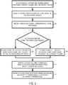
- FIG. 5 is a flow chart illustrating an example of a process that may be implemented to identify channels in a telecommunication system.
- the process described herein with reference to FIGS. 1 and 2 , may be implemented by the channel identification system 116 of FIG. 1 or by any other suitable system or subsystem in a telecommunication system.
- the channel identification system 116 synchronously captures analog signals transmitted by the base station 102 to the head-end unit 108.
- downlink signals may be received from the ports 112a-n of the base station 102 by the interface device 200 of the channel identification system 116 via the channels between ports 112a-n and ports 114a-n.
- the channels may include a primary channel, or the channel having a higher data rate than other channels of the base station 102, and one or more secondary channels.
- the downlink signals may be received at the ports 114a-n of the head-end unit.
- the ports 114a-n may correspond to donor ports of the interface device 200.
- the base station 102 may include two ports 112a, 112b communicatively coupled to two ports 114a, 114b of the head-end unit 108.
- the downlink signals from port 112a may be received at port 114a and the downlink signals from port 112b may be received by port 114b, or the downlink signals from port 112a may be received at port 114b and the downlink signals from port 112b may be received by port 114a.
- the downlink signals may be converted from analog to digital.
- the downlink signals may be digitized by one or more analog-to-digital converters of the interface device 200.
- the synchronous capture of the digitized downlink signals may include sampling the digitized downlink signals at the same time, i.e., a first sample from a first digitized downlink signal and a second sample from second digitized downlink signal may be associated with the same sampling time.
- the synchronous capture may be performed by the field programmable gate array 202 on a backplane of the head-end unit 108.
- the captured samples of the digitized downlink signals may be made available to the digital signal processor 204 and stored in the memory device 208.
- primary and secondary synchronization signals are identified in the synchronously captured samples.
- the downlink signals may be down-sampled (e.g., decimated by 16) to facilitate the identification of the primary and secondary synchronization signals.
- the primary and secondary synchronization signals may be identified by the measurement receiver 206.
- the measurement receiver 206 may retrieve the samples from the memory device 208.
- the measurement receiver 206 may retrieve the samples from the field programmable gate array 202.
- the primary and secondary synchronization signals may be transmitted from one or more ports 112a-n of the base station 102 as signals embed in the downlink signals transmitted to the head-end unit 108.
- primary and secondary synchronization signals may be embedded in only a downlink signal on a single channel (e.g., from one of the ports 112a-n). In other aspects, primary and secondary synchronization signals may be embedded in the downlink signals transmitted on multiple or all of the channels (e.g., from multiple or all of ports 112a-n).
- the primary synchronization signal may be located in a specific OFDM symbol, slot, and sub-frame of a radio frame to enable synchronization of the head-end unit 108 or other equipment in the telecommunication system 100.
- the secondary synchronization signal may be located in the same sub-frame but in an OFDM symbol adjacent to the primary synchronization signal to provide the channel identification system 116 with a cell identifier corresponding to the channel, or port 112a-n, from which the signal was transmitted.
- the cell identifier may enable the head-end unit 108 to determine whether the port 112a-n of the base station 102 from which the primary synchronization signal and secondary synchronization signal are transferred corresponds to the primary channel.
- the broadcast channel may be decoded for the digital signal sample(s) including the primary and secondary synchronization signals.
- decoding the broadcast channel may allow the channel identification system 116 to determine a number of ports transmitting downlink signals from the base station 102 (e.g., 2 ports for a 2x2 MIMO, 4 ports for a 4x4 MIMO, etc.).
- the broadcast channel may also provide bandwidth and frame information for the ports 112a, 112b of the base station.
- the broadcast channel may be decoded using known techniques.
- the down-sampling may be from 30.72e6 to 1.92e6 Hz since the broadcast channel may be centered at 1.08e6 Hz.
- Time synchronization may be performed by the measurement receiver 206 subsequent to the down-sampling by relocating the primary and secondary synchronization signals in the down-sampled signals to identify the frame boundaries and slot numbers.
- MIB master information block
- the cyclic prefix may be removed.
- a fast Fourier transform (FFT) algorithm may be performed for a conversion to the frequency domain for the resource elements.
- Channel estimation and interpolation may be performed in the sub-frame using cell-specific reference signals.
- Channel correction may be performed to the resource elements in the frequency domain and the resource elements carrying broadcast channel information may be extracted according to the number of ports.
- FFT fast Fourier transform
- recovery from the space-frequency block coding may be used.
- the resource elements may be demodulated and mapped to bit sequence.
- descrambling, rate de-matching, and Viterbi decoding may also be performed.
- the cyclic redundancy check (CRC) generated from MIB payload may be checked and compared using an exclusive disjunction operation to zeroes having corresponding 16-bit mask.
- the master information block information may be extracted.
- the master information block information may include a downlink bandwidth, physical hybrid-ARQ indicator channel (PHICH) configuration, system frame number (SNF), and a number of ports.
- PHICH physical hybrid-ARQ indicator channel
- SNF system frame number
- a cell-specific reference signal may be extracted.
- the cell-specific reference signal may be extracted from a downlink signal that does not include the primary and secondary synchronization signals based upon the primary and secondary synchronization signals being embedded only in the downlink signals from one port 112a-n of the base station 102.
- the cell-specific reference signal may be included in downlink signals traversing the primary channel or the secondary channel.
- the cell-specific reference signal may be extracted from the primary channel based upon the synchronization signals being included in downlink signals traversing the secondary channel.
- the cell-specific reference signal may be extracted from the secondary channel based upon the synchronization signals being included in downlink signals traversing the primary channel.
- a cell-specific reference signal may be extracted from a downlink signal traversing a secondary channel based upon primary and secondary synchronization signals being embedded in both primary and secondary channels.
- the cell-specific reference signal may be extracted by re-identifying the primary and secondary synchronization signals at a full sampling rate.
- a search of the primary and secondary synchronization signals may be performed at full rate to achieve more accurate slot synchronization.
- measurement receiver 206 may re-identify retrieved the digital downlink signal samples from original synchronous captures of the samples stored in the memory device 208.
- the measurement receiver 206 may up-sample the previously down-sampled digital signal used to identify to the primary and secondary synchronization signals as described in block 504.
- the result of the search may provide a frame boundary and a slot boundary for the digitized downlink signals.
- the measurement receiver 206 may use this signal information to convert the samples from the time domain to the frequency domain to determine the cell-specific reference signal based on instruction 210 stored in the memory device 208.
- the measurement receiver 206 may convert the samples from the time domain to the frequency domain using a fast Fourier transform (FFT) algorithm.
- FFT fast Fourier transform
- a second cell-specific reference signal may be generated from the digitized downlink signals.
- the second cell-specific reference signal may be generated without using the information from the primary and secondary synchronization signal.
- the second cell-specific reference signal may serve as a hypothesis to the first cell-specific reference signal.
- the second cell-specific reference signal may be a Gold sequence and may be reconstructed using instructions 210 in the memory device 208.
- the second cell-specific reference signal may be generated using known values for the cell identifier, cyclic prefix, slot number, symbol number, and port number for the port 112a-n from which the downlink signal was transmitted.
- a fast Fourier transform (FFT) algorithm may be used to convert the information from the time domain to the frequency domain to generate the cell-specific reference signals from the downlink signals.
- FFT fast Fourier transform
- the first cell-specific reference signal and the second cell-specific reference signal may be correlated and compared to determine a channel identification for the ports 112a-n.
- a channel identification may be verified where the two cell-specific reference signal sequences are near-identical.
- the cell-specific reference signals may be compared based on the location of each cell-specific reference signal and the relative strength of the correlation peak. When a strong correlation at lag zero is found within a given threshold, the hypothesis that the port 112a-n corresponding to the second cell-specific reference signal is from the same port 112a-n as the port 112a-n corresponding to the cell-specific reference signal may be confirmed.
- the results are logged or otherwise stored in a database.
- the channel identification results may be used to determine routing decisions for the downlink signals to the access points. The channel identification results may be discarded where the correlation and comparison is rejected.
- the determination of which port 112a-n of the base station 102 or corresponding port 114a-n of the head-end unit 108 may be used by the channel identification system 116 to perform the autocorrelation functions for determining and verifying channel identification may be based on the location of the primary and secondary synchronization signals and, in some cases, the primary and secondary channels identified by the channel identification system 116.
- a base station provider may locate synchronization signals on one or multiple ports. For example, in a 2x2 MIMO system, synchronization signals may be located on a first port only, on a second port only, or on both a first and second port (e.g., ports 112a, 112b of the base station 102 of FIG. 1 ).
- the ports may be mapped to ports in the telecommunication system (e.g., ports 114a, 114b of the head-end unit 108).
- the mapping of the ports 112a, 112b to ports 114a, 114b may be direct (e.g., port 112a to port 114a, port 112b to port 114b as shown in FIG. 1 ) or may be inversed (e.g., port 112a to port 114b, port 112b to port 114a) to provide six potential scenarios for determining the ports used for correlation.
- the ports 112a, 112b may be directly connected to ports 114a, 114b and the primary and secondary synchronization signals may be embedded in a downlink signal received at port 114a.
- the direct connection informs that the synchronization signals were transmitted from port 112a to port 114a and port 112b to port 114b.
- Ports 112a, 114a may be associated with the primary channel.
- the first cell-specific reference signal may be extracted from the port associated with the non-primary channel, or secondary channel, (e.g., port 114b).
- the second cell-specific reference signal may be generated using information decoded from downlink signals received at port 114a according to some aspects.
- the ports 112a, 112b may be reversely connected to ports 114a, 114b and the primary and secondary synchronization signals may be embedded in a downlink signal received at port 114b.
- Ports 112a, 114b may be associated with the primary channel.
- the first cell-specific reference signal may be extracted from the port associated with the secondary channel (e.g., port 114a).
- the second cell-specific reference signal may be generated using information decoded from downlink signals received at port 114b.
- the ports 112a, 112b may be directly connected to ports 114a, 114b and the primary and secondary synchronization signals may be embedded in downlink signals received at both ports 114a, 114b.
- Ports 112a, 114a may be associated with the primary channel.
- the first cell-specific reference signal may be extracted from the port associated with the secondary channel (e.g., port 114b).
- the second cell-specific reference signal may be generated using information decoded from downlink signals received at port 114a.
- the ports 112a, 112b may be reversely connected to ports 114a, 114b and the primary and secondary synchronization signals may be embedded in downlink signals received at both ports 114a, 114b.
- the reverse connection informs that the synchronization signals were transmitted from port 112a to port 114b and from port 112b to port 114a.
- Ports 112a, 114b may be associated with the primary channel.
- the first cell-specific reference signal may be extracted from the port associated with the secondary channel (e.g., port 114a).
- the second cell-specific reference signal may be generated using information decoded from downlink signals received at port 114b.
- the ports 112a, 112b may be directly connected to ports 114a, 114b and the primary and secondary synchronization signals may be embedded in a downlink signal received at port 114b.
- Ports 112a, 114a may be associated with the primary channel.
- the first cell-specific reference signal may be extracted from the port associated with the primary channel (e.g., port 114a).
- the second cell-specific reference signal may be generated using information decoded from downlink signals received at port 114b.
- the ports 112a, 112b may be reversely connected to ports 114a, 114b and the primary and secondary synchronization signals may be embedded in a downlink signal received at port 114a.
- Ports 112a, 114b may be associated with the primary channel.
- the first cell-specific reference signal may be extracted from the port associated with the primary channel (e.g., port 114b).
- the second cell-specific reference signal may be generated using information decoded from downlink signals received at port 114a.
- the methods for determining the ports 112a-n, 114a-n for correlation of the cell-specific reference signals may be applied to 4x4 MIMO systems with additional scenarios.
- the six scenarios describe specific ports 112a-b, 114a-b and associated channels for correlation in a 2x2 MIMO system, downlink signals from various combinations of ports 112a-b, 114a-b may be used for correlation without departing from the scope of the present disclosures.
- a correlation as described in block 510 of FIG. 5 may be graphically represented.
- MATLAB scripts may be used to analyze correlation of the first and second cell-specific reference signals.
- FIGs. 6 and 7 include graphs illustrating examples of simulated results of the correlation and comparison of the cell-specific reference signal sequences in a 2x2 MIMO system.
- graph 600 represents a successful correlation of the first and second cell-specific reference signals.
- the x-axis may represent offset or lag and the y-axis may represent an absolute value.
- six resource blocks of the cell-specific reference signals are used in the simulation. But, in some aspects, decoding the broadcast channel prior to correlation may provide signal information such as bandwidth information that may allow for longer sequences.
- the peak 602 may represent a match between the first and second cell-specific reference signals, indicating a strong correlation at the zero lag (e.g., twelve) of the correlation.
- FIG. 7 shows a graph 700 indicating an unsuccessful correlation.
- the correlation may be the equivalent to correlating a known cell-specific reference signal Gold sequence with random noise.
Claims (13)
- Kanalidentifizierungssystem für ein Multiple Input, Multiple Output, MIMO, Telekommunikationssystem, das drahtlos mit Endgeräten kommuniziert, umfassend:eine Schnittstellenvorrichtung, die konfiguriert ist, um Downlink-Signale auf Kanälen zu empfangen, die einem ersten Port und einem zweiten Port einer Basisstation entsprechen; undeine Verarbeitungsvorrichtung, umfassend mindestens einen Field Programmable Gate Array, wobei die Verarbeitungsvorrichtung konfiguriert ist für:synchrones Erfassen von Abtastungen der Downlink-Signale, die von der Basisstation empfangen werden;Extrahieren eines ersten zellspezifischen Referenzsignals aus den Abtastungen von einer oder mehreren der Downlink-Signale,Erzeugen eines zweiten zellspezifischen Referenzsignals basierend auf bekannten Parametern, die zur Übertragung mindestens eines der Downlink-Signale verwendet werden; undErmitteln einer Kanalidentifizierung, die mindestens einem Kanal der Kanäle entspricht, durch Korrelieren des ersten zellspezifischen Referenzsignals und des zweiten zellspezifischen Referenzsignals.
- Kanalidentifizierungssystem nach Anspruch 1, wobei die Verarbeitungsvorrichtung ferner konfiguriert ist für:
Decodieren eines Rundfunkkanals für ein Signal der Downlink-Signale mit einem eingebetteten Synchronisationssignal. - Kanalidentifizierungssystem nach Anspruch 1, wobei das erste zellspezifische Referenzsignal extrahiert wird aus einem von: (a) einem ersten Downlink-Signal der Downlink-Signale, das kein eingebettetes Synchronisationssignal enthält, oder (b) einem zweiten Downlink-Signal der Downlink-Signale, das das eingebettete Synchronisationssignal enthält und einem Sekundärkanal der Kanäle zugeordnet ist.
- Kanalidentifizierungssystem nach Anspruch 1, wobei die Verarbeitungsvorrichtung ferner konfiguriert ist, um das erste zellspezifische Referenzsignal unter Verwendung einer Zellkennung, eines zyklischen Präfixes, einer Steckplatznummer, einer Symbolnummer oder einer Portnummer, die einer Abtastung des ersten Downlink-Signals oder des zweiten Downlink-Signals entsprechen, zu ermitteln.
- Kanalidentifizierungssystem nach Anspruch 1, ferner umfassend eine Speichervorrichtung, die konfiguriert ist, um die Abtastungen der Downlink-Signale zu speichern, die von der Verarbeitungsvorrichtung verwendet werden können, um das zweite zellspezifische Referenzsignal zu ermitteln.
- Kanalidentifizierungssystem nach Anspruch 1, wobei die bekannten Parameter eine Zellkennung, ein zyklisches Präfix, eine Steckplatznummer, eine Symbolnummer oder eine Portnummer umfassen, die einer gespeicherten Abtastung von dem mindestens einen der Downlink-Signale entsprechen.
- Kanalidentifizierungssystem nach Anspruch 1, wobei die Verarbeitungsvorrichtung ferner mindestens eine Messwert-Empfangseinrichtung umfasst, die konfiguriert ist, um Abtastungen der Downlink-Signale, die von der Basisstation empfangen werden, zu empfangen und ein primäres Synchronisationssignal und ein sekundäres Synchronisationssignal, eingebettet in mindestens einem der Downlink-Signale, zu identifizieren.
- Kanalidentifizierungssystem nach Anspruch 1, wobei die Verarbeitungsvorrichtung in einer Head-End-Einheit des MIMO-Telekommunikationssystems angeordnet ist.
- Verfahren, wobei das Verfahren von einem Multiple Input, Multiple Output, MIMO, Telekommunikationssystem durchgeführt wird, das drahtlos mit Endgeräten kommuniziert, wobei das Verfahren umfasst:Empfangen einer Vielzahl von Signalen von Ports einer Basisstation, wobei die Ports mindestens einem Primärkanal und einem Sekundärkanal entsprechen;synchrones Erfassen digitaler Abtastungen der Vielzahl von Signalen; und Extrahieren eines ersten zellspezifischen Referenzsignals aus den digitalen Abtastungen von einem oder mehreren der Vielzahl von Signalen;Erzeugen eines zweiten zellspezifischen Referenzsignals basierend auf bekannten Parametern, die zur Übertragung mindestens eines der Vielzahl von Signalen verwendet werden; undErmitteln einer Kanalidentifizierung, die einem Port der Basisstation entspricht, durch Korrelieren des ersten zellspezifischen Referenzsignals und des zweiten zellspezifischen Referenzsignals.
- Verfahren nach Anspruch 9, ferner umfassend:
Decodieren eines Rundfunkkanals basierend auf einem Ort eines eingebetteten Synchronisationssignals in der Vielzahl von Signalen. - Verfahren nach Anspruch 9, ferner umfassend:Identifizieren eines oder mehrerer primärer oder sekundärer Synchronisationssignale nach dem Downsampling der Vielzahl von Signalen; underneutes Identifizieren des einen oder der mehreren primären oder sekundären Synchronisationssignale in einer gespeicherten Abtastung des ersten Signals oder des zweiten Signals bei einer vollständigen Abtastrate.
- Verfahren nach Anspruch 9, wobei die bekannten Parameter die Verwendung einer Zellkennung, eines zyklischen Präfixes, einer Steckplatznummer, einer Symbolnummer oder einer Portnummer umfassen, die einer gespeicherten Abtastung von dem einen der Vielzahl von Signalen entspricht.
- Verfahren nach Anspruch 9, wobei das erste zellenspezifische Referenzsignal aus einem der Folgenden extrahiert wird: (a) einem ersten Downlink-Signal der Vielzahl von Signalen, das kein eingebettetes Synchronisationssignal enthält, oder (b) einem zweiten Downlink-Signal der Vielzahl von Signalen, das das eingebettete Synchronisationssignal enthält und dem Sekundärkanal zugeordnet ist.
Applications Claiming Priority (3)
| Application Number | Priority Date | Filing Date | Title |
|---|---|---|---|
| US201562114658P | 2015-02-11 | 2015-02-11 | |
| EP16749581.1A EP3257211B1 (de) | 2015-02-11 | 2016-01-26 | Kanalidentifizierung in einem mimo-telekommunikationssystem |
| PCT/US2016/014821 WO2016130310A1 (en) | 2015-02-11 | 2016-01-26 | Channel identification in a mimo telecommunication system |
Related Parent Applications (2)
| Application Number | Title | Priority Date | Filing Date |
|---|---|---|---|
| EP16749581.1A Division EP3257211B1 (de) | 2015-02-11 | 2016-01-26 | Kanalidentifizierung in einem mimo-telekommunikationssystem |
| EP16749581.1A Division-Into EP3257211B1 (de) | 2015-02-11 | 2016-01-26 | Kanalidentifizierung in einem mimo-telekommunikationssystem |
Publications (2)
| Publication Number | Publication Date |
|---|---|
| EP3588889A1 EP3588889A1 (de) | 2020-01-01 |
| EP3588889B1 true EP3588889B1 (de) | 2021-03-10 |
Family
ID=56615075
Family Applications (2)
| Application Number | Title | Priority Date | Filing Date |
|---|---|---|---|
| EP19191548.7A Active EP3588889B1 (de) | 2015-02-11 | 2016-01-26 | Kanalidentifizierung in einem mimo-telekommunikationssystem |
| EP16749581.1A Active EP3257211B1 (de) | 2015-02-11 | 2016-01-26 | Kanalidentifizierung in einem mimo-telekommunikationssystem |
Family Applications After (1)
| Application Number | Title | Priority Date | Filing Date |
|---|---|---|---|
| EP16749581.1A Active EP3257211B1 (de) | 2015-02-11 | 2016-01-26 | Kanalidentifizierung in einem mimo-telekommunikationssystem |
Country Status (4)
| Country | Link |
|---|---|
| US (2) | US10396956B2 (de) |
| EP (2) | EP3588889B1 (de) |
| AU (1) | AU2016218390C1 (de) |
| WO (1) | WO2016130310A1 (de) |
Families Citing this family (5)
| Publication number | Priority date | Publication date | Assignee | Title |
|---|---|---|---|---|
| AU2016218390C1 (en) * | 2015-02-11 | 2020-04-16 | Commscope Technologies Llc | Channel identification in a MIMO telecommunication system |
| EP3326342B1 (de) * | 2015-07-20 | 2019-09-25 | Telefonaktiebolaget LM Ericsson (publ) | Sende-empfängerarchitekture welche die alte zeitstrukture durch einfügen und entfernen von zyklischem präfix bei der alten abtastungsrate beibehält |
| WO2018102127A1 (en) * | 2016-11-29 | 2018-06-07 | Commscope Technologies Llc | Methods of reducing power consumption in a cellular network based on traffic analytics |
| FR3094169B1 (fr) * | 2019-03-18 | 2021-02-12 | Continental Automotive | Système d’authentification au niveau de la couche physique pour système de communication radio |
| JP2022552941A (ja) * | 2019-09-26 | 2022-12-21 | コムスコープ テクノロジーズ リミティド ライアビリティ カンパニー | 分散アンテナシステムのマスタユニットのためのパッシブバックプレーンアーキテクチャ |
Family Cites Families (28)
| Publication number | Priority date | Publication date | Assignee | Title |
|---|---|---|---|---|
| US3369177A (en) * | 1965-10-15 | 1968-02-13 | Bell Telephone Labor Inc | Method of identifying conductors in a cable by establishing conductor connection groupings at both ends of the cable |
| US7053824B2 (en) * | 2001-11-06 | 2006-05-30 | Global Locate, Inc. | Method and apparatus for receiving a global positioning system signal using a cellular acquisition signal |
| US7848770B2 (en) * | 2006-08-29 | 2010-12-07 | Lgc Wireless, Inc. | Distributed antenna communications system and methods of implementing thereof |
| WO2008099383A2 (en) * | 2007-02-12 | 2008-08-21 | Mobileaccess Networks Ltd. | Mimo-adapted distributed antenna system |
| KR20090001359A (ko) * | 2007-06-29 | 2009-01-08 | 엘지전자 주식회사 | 방송 수신이 가능한 텔레매틱스 단말기 및 방송 신호 처리방법 |
| KR101615235B1 (ko) * | 2009-09-09 | 2016-04-25 | 엘지전자 주식회사 | MU-MIMO 방식을 지원하는 무선 통신 시스템에서 CoMP 동작에서의 참조신호 송수신 방법 및 이를 이용하는 단말 장치와 기지국 장치 |
| JP5265657B2 (ja) * | 2010-12-27 | 2013-08-14 | シャープ株式会社 | 基地局装置、端末装置、通信システムおよび通信方法 |
| EP2705612B1 (de) * | 2011-05-02 | 2023-06-07 | BlackBerry Limited | Verfahren und system zur drahtlosen kommunikation mit räumlich versetzten funkköpfen |
| CN103782632B (zh) * | 2011-07-11 | 2017-09-29 | 华为技术有限公司 | 无线通信系统中的小区搜索方法 |
| KR20130014236A (ko) * | 2011-07-29 | 2013-02-07 | 주식회사 팬택 | 무선통신 시스템에서 참조신호의 전송 방법 및 장치 |
| CN102984746A (zh) * | 2011-09-05 | 2013-03-20 | 爱立信(中国)通信有限公司 | 提高网络中性能的参考信号功率测量和报告 |
| EP2777233B1 (de) * | 2011-11-07 | 2018-05-30 | Telefonaktiebolaget LM Ericsson (publ) | Verfahren und vorrichtung zur signalisierung von demodulationsreferenzsignalen |
| US9629050B2 (en) * | 2012-02-03 | 2017-04-18 | Telefonaktiebolaget Lm Ericsson (Publ) | Method, apparatus and computer program for cell identification |
| US9331827B2 (en) * | 2012-05-14 | 2016-05-03 | Telefonaktiebolaget Lm Ericsson (Publ) | Enhanced receiver configuration adaptive to cyclic prefix configuration |
| DE202013012858U1 (de) | 2012-08-09 | 2021-05-07 | Axel Wireless Ltd. | Kapazitätszentriertes digitales verteiltes Antennensystem |
| CN103687042B (zh) * | 2012-09-03 | 2018-05-15 | 中兴通讯股份有限公司 | 一种物理下行共享信道的传输方法及系统 |
| KR101898050B1 (ko) * | 2012-10-15 | 2018-10-04 | 삼성전자주식회사 | 무선 통신시스템에서 가상셀 브레싱에 기반한 핸드오버 처리 방법 및 장치 |
| EP2733853A1 (de) * | 2012-11-19 | 2014-05-21 | Gemalto M2M GmbH | Verfahren, Vorrichtung und System zur Erkennung eines Störsenders |
| US9516659B2 (en) * | 2012-12-06 | 2016-12-06 | Intel Corporation | Carrier type (NCT) information embedded in synchronization signal |
| US9661601B2 (en) * | 2012-12-13 | 2017-05-23 | Qualcomm Incorporated | Crowdsourcing information in a communication network using small cells |
| WO2014130091A1 (en) * | 2013-02-22 | 2014-08-28 | Intel IP Corporation | Systems and methods for access network selection and traffic routing |
| US9479298B2 (en) * | 2013-07-08 | 2016-10-25 | Intel IP Corporation | Demodulation reference signals (DMRS)for side information for interference cancellation |
| JP2015046853A (ja) * | 2013-08-02 | 2015-03-12 | 株式会社Nttドコモ | ユーザ装置、基地局、干渉低減方法、及び干渉低減制御情報通知方法 |
| JP2015061248A (ja) * | 2013-09-20 | 2015-03-30 | 株式会社日立製作所 | 基地局、無線通信システム、及び無線通信方法 |
| US10244507B2 (en) * | 2013-09-24 | 2019-03-26 | Andrew Wireless Systems Gmbh | Distributed processing in a centralized radio access network |
| JP6117722B2 (ja) * | 2014-01-17 | 2017-04-19 | 株式会社Nttドコモ | 基地局、ユーザ装置、干渉低減制御情報通知方法、及び干渉低減方法 |
| EP3203661B1 (de) * | 2014-10-01 | 2020-01-01 | LG Electronics Inc. | Verfahren und vorrichtung zur übertragung von interferenzunterdrückungsinformationen zur interferenzunterdrückung zwischen zellen |
| AU2016218390C1 (en) * | 2015-02-11 | 2020-04-16 | Commscope Technologies Llc | Channel identification in a MIMO telecommunication system |
-
2016
- 2016-01-26 AU AU2016218390A patent/AU2016218390C1/en active Active
- 2016-01-26 US US15/549,057 patent/US10396956B2/en active Active
- 2016-01-26 EP EP19191548.7A patent/EP3588889B1/de active Active
- 2016-01-26 WO PCT/US2016/014821 patent/WO2016130310A1/en active Application Filing
- 2016-01-26 EP EP16749581.1A patent/EP3257211B1/de active Active
-
2019
- 2019-07-05 US US16/504,084 patent/US10924243B2/en active Active
Non-Patent Citations (1)
| Title |
|---|
| None * |
Also Published As
| Publication number | Publication date |
|---|---|
| AU2016218390A1 (en) | 2017-07-06 |
| EP3257211A1 (de) | 2017-12-20 |
| WO2016130310A1 (en) | 2016-08-18 |
| EP3588889A1 (de) | 2020-01-01 |
| US10924243B2 (en) | 2021-02-16 |
| US10396956B2 (en) | 2019-08-27 |
| EP3257211B1 (de) | 2019-09-25 |
| AU2016218390C1 (en) | 2020-04-16 |
| US20180026760A1 (en) | 2018-01-25 |
| AU2016218390B2 (en) | 2019-10-31 |
| US20190327040A1 (en) | 2019-10-24 |
| EP3257211A4 (de) | 2018-09-26 |
Similar Documents
| Publication | Publication Date | Title |
|---|---|---|
| US10924243B2 (en) | Channel identification in a MIMO telecommunications system | |
| CN108111270B (zh) | 导频信号发送、接收方法及装置 | |
| US9923649B2 (en) | Interference measurement method, network-side device and terminal device for improving the interference measurement effect and thus the demodulation performance of data and control channels | |
| CN101142775B (zh) | 无线电通信设备 | |
| US20150198696A1 (en) | Method for terminal positioning, base station and user equipment | |
| JP6553294B2 (ja) | 無線通信システム、通信ユニット、端末及び通信システムにおけるチャネル推定の方法 | |
| JP2017204895A (ja) | 信号補償のための多入力多出力直交周波数分割多重通信のシステムおよび方法 | |
| EP3402265A1 (de) | Multiplexverfahren für physikalischen downlink-kanal für schmalbandiges internet der dinge sowie basisstation und benutzergerät | |
| CN108260209B (zh) | 一种用于随机接入的ue、基站中的方法和装置 | |
| EP2916480B1 (de) | Zuordnung von mib-daten in einem lte-kommunikationsystem unter verwendung eines physikalischen rundfunkkanals des neuen trägertyps | |
| CN107872254B (zh) | 一种用于随机接入的ue、基站中的方法和装置 | |
| US20110129027A1 (en) | Wireless communication base station device, wireless communication terminal device, and method for setting cyclic delay | |
| EP3331298B1 (de) | Vorrichtung und entsprechendes verfahren zur srs-übertragung | |
| EP3579444A1 (de) | Sendevorrichtung, empfangsvorrichtung, basisstation, endgerät und sendeverfahren | |
| KR100949454B1 (ko) | 무선통신시스템에서 신호대 간섭 및 잡음비 추정 장치 및방법 | |
| EP3448098A1 (de) | Synchronisationssignalsende- und -empfangsverfahren, basisstation und benutzergerät | |
| CN108400947B (zh) | 干扰噪声协方差矩阵估计方法、装置及系统 | |
| US20220030535A1 (en) | High Resolution Timing Advance Estimation Based on PRACH | |
| CN109314596B (zh) | 传输数据的方法、信道估计的方法和装置 | |
| US20200099565A1 (en) | High Resolution Timing Advance Estimation Based on PRACH and Sparse IFFT Algorithm for LTE PRACH | |
| WO2017004988A1 (zh) | 射频拉远单元的确定方法及装置、存储介质 | |
| EP3001624A1 (de) | Verfahren und Sender zur Erzeugung eines Mehrträgersignals | |
| EP3098997B1 (de) | Datensende- und datenempfangsdetektionsverfahren, basisstation und benutzergerät | |
| CN112236983B (zh) | 信道估计的方法、装置、通信设备及存储介质 | |
| EP3119023A1 (de) | Verfahren zum multiplexen und zuweisen von uplink-referenzsignalen in einem funkkommunikationssystem mit einem ersten netzwerkknoten und einem zweiten netzwerkknoten |
Legal Events
| Date | Code | Title | Description |
|---|---|---|---|
| PUAI | Public reference made under article 153(3) epc to a published international application that has entered the european phase |
Free format text: ORIGINAL CODE: 0009012 |
|
| STAA | Information on the status of an ep patent application or granted ep patent |
Free format text: STATUS: THE APPLICATION HAS BEEN PUBLISHED |
|
| AC | Divisional application: reference to earlier application |
Ref document number: 3257211 Country of ref document: EP Kind code of ref document: P |
|
| AK | Designated contracting states |
Kind code of ref document: A1 Designated state(s): AL AT BE BG CH CY CZ DE DK EE ES FI FR GB GR HR HU IE IS IT LI LT LU LV MC MK MT NL NO PL PT RO RS SE SI SK SM TR |
|
| STAA | Information on the status of an ep patent application or granted ep patent |
Free format text: STATUS: REQUEST FOR EXAMINATION WAS MADE |
|
| 17P | Request for examination filed |
Effective date: 20200622 |
|
| RBV | Designated contracting states (corrected) |
Designated state(s): AL AT BE BG CH CY CZ DE DK EE ES FI FR GB GR HR HU IE IS IT LI LT LU LV MC MK MT NL NO PL PT RO RS SE SI SK SM TR |
|
| GRAP | Despatch of communication of intention to grant a patent |
Free format text: ORIGINAL CODE: EPIDOSNIGR1 |
|
| STAA | Information on the status of an ep patent application or granted ep patent |
Free format text: STATUS: GRANT OF PATENT IS INTENDED |
|
| RIC1 | Information provided on ipc code assigned before grant |
Ipc: H04L 27/26 20060101AFI20200813BHEP Ipc: H04B 7/0413 20170101ALI20200813BHEP Ipc: H04W 88/08 20090101ALI20200813BHEP Ipc: H04L 5/00 20060101ALI20200813BHEP |
|
| INTG | Intention to grant announced |
Effective date: 20200828 |
|
| GRAS | Grant fee paid |
Free format text: ORIGINAL CODE: EPIDOSNIGR3 |
|
| STAA | Information on the status of an ep patent application or granted ep patent |
Free format text: STATUS: GRANT OF PATENT IS INTENDED |
|
| GRAA | (expected) grant |
Free format text: ORIGINAL CODE: 0009210 |
|
| STAA | Information on the status of an ep patent application or granted ep patent |
Free format text: STATUS: THE PATENT HAS BEEN GRANTED |
|
| AC | Divisional application: reference to earlier application |
Ref document number: 3257211 Country of ref document: EP Kind code of ref document: P |
|
| AK | Designated contracting states |
Kind code of ref document: B1 Designated state(s): AL AT BE BG CH CY CZ DE DK EE ES FI FR GB GR HR HU IE IS IT LI LT LU LV MC MK MT NL NO PL PT RO RS SE SI SK SM TR |
|
| REG | Reference to a national code |
Ref country code: GB Ref legal event code: FG4D |
|
| REG | Reference to a national code |
Ref country code: AT Ref legal event code: REF Ref document number: 1371081 Country of ref document: AT Kind code of ref document: T Effective date: 20210315 Ref country code: CH Ref legal event code: EP |
|
| REG | Reference to a national code |
Ref country code: IE Ref legal event code: FG4D |
|
| REG | Reference to a national code |
Ref country code: DE Ref legal event code: R096 Ref document number: 602016054299 Country of ref document: DE |
|
| REG | Reference to a national code |
Ref country code: LT Ref legal event code: MG9D |
|
| PG25 | Lapsed in a contracting state [announced via postgrant information from national office to epo] |
Ref country code: LT Free format text: LAPSE BECAUSE OF FAILURE TO SUBMIT A TRANSLATION OF THE DESCRIPTION OR TO PAY THE FEE WITHIN THE PRESCRIBED TIME-LIMIT Effective date: 20210310 Ref country code: NO Free format text: LAPSE BECAUSE OF FAILURE TO SUBMIT A TRANSLATION OF THE DESCRIPTION OR TO PAY THE FEE WITHIN THE PRESCRIBED TIME-LIMIT Effective date: 20210610 Ref country code: GR Free format text: LAPSE BECAUSE OF FAILURE TO SUBMIT A TRANSLATION OF THE DESCRIPTION OR TO PAY THE FEE WITHIN THE PRESCRIBED TIME-LIMIT Effective date: 20210611 Ref country code: FI Free format text: LAPSE BECAUSE OF FAILURE TO SUBMIT A TRANSLATION OF THE DESCRIPTION OR TO PAY THE FEE WITHIN THE PRESCRIBED TIME-LIMIT Effective date: 20210310 Ref country code: BG Free format text: LAPSE BECAUSE OF FAILURE TO SUBMIT A TRANSLATION OF THE DESCRIPTION OR TO PAY THE FEE WITHIN THE PRESCRIBED TIME-LIMIT Effective date: 20210610 Ref country code: HR Free format text: LAPSE BECAUSE OF FAILURE TO SUBMIT A TRANSLATION OF THE DESCRIPTION OR TO PAY THE FEE WITHIN THE PRESCRIBED TIME-LIMIT Effective date: 20210310 |
|
| REG | Reference to a national code |
Ref country code: AT Ref legal event code: MK05 Ref document number: 1371081 Country of ref document: AT Kind code of ref document: T Effective date: 20210310 |
|
| REG | Reference to a national code |
Ref country code: NL Ref legal event code: MP Effective date: 20210310 |
|
| PG25 | Lapsed in a contracting state [announced via postgrant information from national office to epo] |
Ref country code: RS Free format text: LAPSE BECAUSE OF FAILURE TO SUBMIT A TRANSLATION OF THE DESCRIPTION OR TO PAY THE FEE WITHIN THE PRESCRIBED TIME-LIMIT Effective date: 20210310 Ref country code: SE Free format text: LAPSE BECAUSE OF FAILURE TO SUBMIT A TRANSLATION OF THE DESCRIPTION OR TO PAY THE FEE WITHIN THE PRESCRIBED TIME-LIMIT Effective date: 20210310 Ref country code: LV Free format text: LAPSE BECAUSE OF FAILURE TO SUBMIT A TRANSLATION OF THE DESCRIPTION OR TO PAY THE FEE WITHIN THE PRESCRIBED TIME-LIMIT Effective date: 20210310 |
|
| PG25 | Lapsed in a contracting state [announced via postgrant information from national office to epo] |
Ref country code: NL Free format text: LAPSE BECAUSE OF FAILURE TO SUBMIT A TRANSLATION OF THE DESCRIPTION OR TO PAY THE FEE WITHIN THE PRESCRIBED TIME-LIMIT Effective date: 20210310 |
|
| PG25 | Lapsed in a contracting state [announced via postgrant information from national office to epo] |
Ref country code: EE Free format text: LAPSE BECAUSE OF FAILURE TO SUBMIT A TRANSLATION OF THE DESCRIPTION OR TO PAY THE FEE WITHIN THE PRESCRIBED TIME-LIMIT Effective date: 20210310 Ref country code: CZ Free format text: LAPSE BECAUSE OF FAILURE TO SUBMIT A TRANSLATION OF THE DESCRIPTION OR TO PAY THE FEE WITHIN THE PRESCRIBED TIME-LIMIT Effective date: 20210310 Ref country code: SM Free format text: LAPSE BECAUSE OF FAILURE TO SUBMIT A TRANSLATION OF THE DESCRIPTION OR TO PAY THE FEE WITHIN THE PRESCRIBED TIME-LIMIT Effective date: 20210310 Ref country code: AT Free format text: LAPSE BECAUSE OF FAILURE TO SUBMIT A TRANSLATION OF THE DESCRIPTION OR TO PAY THE FEE WITHIN THE PRESCRIBED TIME-LIMIT Effective date: 20210310 |
|
| PG25 | Lapsed in a contracting state [announced via postgrant information from national office to epo] |
Ref country code: PL Free format text: LAPSE BECAUSE OF FAILURE TO SUBMIT A TRANSLATION OF THE DESCRIPTION OR TO PAY THE FEE WITHIN THE PRESCRIBED TIME-LIMIT Effective date: 20210310 Ref country code: SK Free format text: LAPSE BECAUSE OF FAILURE TO SUBMIT A TRANSLATION OF THE DESCRIPTION OR TO PAY THE FEE WITHIN THE PRESCRIBED TIME-LIMIT Effective date: 20210310 Ref country code: PT Free format text: LAPSE BECAUSE OF FAILURE TO SUBMIT A TRANSLATION OF THE DESCRIPTION OR TO PAY THE FEE WITHIN THE PRESCRIBED TIME-LIMIT Effective date: 20210712 Ref country code: RO Free format text: LAPSE BECAUSE OF FAILURE TO SUBMIT A TRANSLATION OF THE DESCRIPTION OR TO PAY THE FEE WITHIN THE PRESCRIBED TIME-LIMIT Effective date: 20210310 Ref country code: IS Free format text: LAPSE BECAUSE OF FAILURE TO SUBMIT A TRANSLATION OF THE DESCRIPTION OR TO PAY THE FEE WITHIN THE PRESCRIBED TIME-LIMIT Effective date: 20210710 |
|
| REG | Reference to a national code |
Ref country code: DE Ref legal event code: R097 Ref document number: 602016054299 Country of ref document: DE |
|
| PLBE | No opposition filed within time limit |
Free format text: ORIGINAL CODE: 0009261 |
|
| STAA | Information on the status of an ep patent application or granted ep patent |
Free format text: STATUS: NO OPPOSITION FILED WITHIN TIME LIMIT |
|
| PG25 | Lapsed in a contracting state [announced via postgrant information from national office to epo] |
Ref country code: ES Free format text: LAPSE BECAUSE OF FAILURE TO SUBMIT A TRANSLATION OF THE DESCRIPTION OR TO PAY THE FEE WITHIN THE PRESCRIBED TIME-LIMIT Effective date: 20210310 Ref country code: DK Free format text: LAPSE BECAUSE OF FAILURE TO SUBMIT A TRANSLATION OF THE DESCRIPTION OR TO PAY THE FEE WITHIN THE PRESCRIBED TIME-LIMIT Effective date: 20210310 Ref country code: AL Free format text: LAPSE BECAUSE OF FAILURE TO SUBMIT A TRANSLATION OF THE DESCRIPTION OR TO PAY THE FEE WITHIN THE PRESCRIBED TIME-LIMIT Effective date: 20210310 |
|
| 26N | No opposition filed |
Effective date: 20211213 |
|
| PG25 | Lapsed in a contracting state [announced via postgrant information from national office to epo] |
Ref country code: SI Free format text: LAPSE BECAUSE OF FAILURE TO SUBMIT A TRANSLATION OF THE DESCRIPTION OR TO PAY THE FEE WITHIN THE PRESCRIBED TIME-LIMIT Effective date: 20210310 |
|
| PG25 | Lapsed in a contracting state [announced via postgrant information from national office to epo] |
Ref country code: IS Free format text: LAPSE BECAUSE OF FAILURE TO SUBMIT A TRANSLATION OF THE DESCRIPTION OR TO PAY THE FEE WITHIN THE PRESCRIBED TIME-LIMIT Effective date: 20210710 |
|
| PG25 | Lapsed in a contracting state [announced via postgrant information from national office to epo] |
Ref country code: MC Free format text: LAPSE BECAUSE OF FAILURE TO SUBMIT A TRANSLATION OF THE DESCRIPTION OR TO PAY THE FEE WITHIN THE PRESCRIBED TIME-LIMIT Effective date: 20210310 |
|
| REG | Reference to a national code |
Ref country code: CH Ref legal event code: PL |
|
| GBPC | Gb: european patent ceased through non-payment of renewal fee |
Effective date: 20220126 |
|
| REG | Reference to a national code |
Ref country code: BE Ref legal event code: MM Effective date: 20220131 |
|
| PG25 | Lapsed in a contracting state [announced via postgrant information from national office to epo] |
Ref country code: LU Free format text: LAPSE BECAUSE OF NON-PAYMENT OF DUE FEES Effective date: 20220126 Ref country code: GB Free format text: LAPSE BECAUSE OF NON-PAYMENT OF DUE FEES Effective date: 20220126 |
|
| PG25 | Lapsed in a contracting state [announced via postgrant information from national office to epo] |
Ref country code: BE Free format text: LAPSE BECAUSE OF NON-PAYMENT OF DUE FEES Effective date: 20220131 |
|
| PG25 | Lapsed in a contracting state [announced via postgrant information from national office to epo] |
Ref country code: LI Free format text: LAPSE BECAUSE OF NON-PAYMENT OF DUE FEES Effective date: 20220131 Ref country code: CH Free format text: LAPSE BECAUSE OF NON-PAYMENT OF DUE FEES Effective date: 20220131 |
|
| PG25 | Lapsed in a contracting state [announced via postgrant information from national office to epo] |
Ref country code: IE Free format text: LAPSE BECAUSE OF NON-PAYMENT OF DUE FEES Effective date: 20220126 |
|
| PGFP | Annual fee paid to national office [announced via postgrant information from national office to epo] |
Ref country code: FR Payment date: 20230125 Year of fee payment: 8 |
|
| PGFP | Annual fee paid to national office [announced via postgrant information from national office to epo] |
Ref country code: IT Payment date: 20230120 Year of fee payment: 8 Ref country code: DE Payment date: 20230127 Year of fee payment: 8 |
|
| P01 | Opt-out of the competence of the unified patent court (upc) registered |
Effective date: 20230530 |
|
| PG25 | Lapsed in a contracting state [announced via postgrant information from national office to epo] |
Ref country code: MK Free format text: LAPSE BECAUSE OF FAILURE TO SUBMIT A TRANSLATION OF THE DESCRIPTION OR TO PAY THE FEE WITHIN THE PRESCRIBED TIME-LIMIT Effective date: 20210310 Ref country code: CY Free format text: LAPSE BECAUSE OF FAILURE TO SUBMIT A TRANSLATION OF THE DESCRIPTION OR TO PAY THE FEE WITHIN THE PRESCRIBED TIME-LIMIT Effective date: 20210310 |
|
| PGFP | Annual fee paid to national office [announced via postgrant information from national office to epo] |
Ref country code: DE Payment date: 20240129 Year of fee payment: 9 |