EP3588839B1 - Signalempfangsvorrichtung und empfangsverfahren - Google Patents
Signalempfangsvorrichtung und empfangsverfahren Download PDFInfo
- Publication number
- EP3588839B1 EP3588839B1 EP18792163.0A EP18792163A EP3588839B1 EP 3588839 B1 EP3588839 B1 EP 3588839B1 EP 18792163 A EP18792163 A EP 18792163A EP 3588839 B1 EP3588839 B1 EP 3588839B1
- Authority
- EP
- European Patent Office
- Prior art keywords
- pulse signal
- optical pulse
- local
- frequency
- signal
- Prior art date
- Legal status (The legal status is an assumption and is not a legal conclusion. Google has not performed a legal analysis and makes no representation as to the accuracy of the status listed.)
- Active
Links
Images




Classifications
-
- H—ELECTRICITY
- H04—ELECTRIC COMMUNICATION TECHNIQUE
- H04B—TRANSMISSION
- H04B10/00—Transmission systems employing electromagnetic waves other than radio-waves, e.g. infrared, visible or ultraviolet light, or employing corpuscular radiation, e.g. quantum communication
- H04B10/70—Photonic quantum communication
-
- H—ELECTRICITY
- H04—ELECTRIC COMMUNICATION TECHNIQUE
- H04L—TRANSMISSION OF DIGITAL INFORMATION, e.g. TELEGRAPHIC COMMUNICATION
- H04L9/00—Cryptographic mechanisms or cryptographic arrangements for secret or secure communications; Network security protocols
- H04L9/08—Key distribution or management, e.g. generation, sharing or updating, of cryptographic keys or passwords
- H04L9/0816—Key establishment, i.e. cryptographic processes or cryptographic protocols whereby a shared secret becomes available to two or more parties, for subsequent use
- H04L9/0852—Quantum cryptography
- H04L9/0858—Details about key distillation or coding, e.g. reconciliation, error correction, privacy amplification, polarisation coding or phase coding
-
- H—ELECTRICITY
- H01—ELECTRIC ELEMENTS
- H01S—DEVICES USING THE PROCESS OF LIGHT AMPLIFICATION BY STIMULATED EMISSION OF RADIATION [LASER] TO AMPLIFY OR GENERATE LIGHT; DEVICES USING STIMULATED EMISSION OF ELECTROMAGNETIC RADIATION IN WAVE RANGES OTHER THAN OPTICAL
- H01S5/00—Semiconductor lasers
- H01S5/06—Arrangements for controlling the laser output parameters, e.g. by operating on the active medium
- H01S5/062—Arrangements for controlling the laser output parameters, e.g. by operating on the active medium by varying the potential of the electrodes
- H01S5/06209—Arrangements for controlling the laser output parameters, e.g. by operating on the active medium by varying the potential of the electrodes in single-section lasers
- H01S5/06216—Pulse modulation or generation
-
- H—ELECTRICITY
- H04—ELECTRIC COMMUNICATION TECHNIQUE
- H04B—TRANSMISSION
- H04B10/00—Transmission systems employing electromagnetic waves other than radio-waves, e.g. infrared, visible or ultraviolet light, or employing corpuscular radiation, e.g. quantum communication
- H04B10/50—Transmitters
- H04B10/508—Pulse generation, e.g. generation of solitons
-
- H—ELECTRICITY
- H04—ELECTRIC COMMUNICATION TECHNIQUE
- H04B—TRANSMISSION
- H04B10/00—Transmission systems employing electromagnetic waves other than radio-waves, e.g. infrared, visible or ultraviolet light, or employing corpuscular radiation, e.g. quantum communication
- H04B10/50—Transmitters
- H04B10/516—Details of coding or modulation
- H04B10/524—Pulse modulation
-
- H—ELECTRICITY
- H04—ELECTRIC COMMUNICATION TECHNIQUE
- H04B—TRANSMISSION
- H04B10/00—Transmission systems employing electromagnetic waves other than radio-waves, e.g. infrared, visible or ultraviolet light, or employing corpuscular radiation, e.g. quantum communication
- H04B10/80—Optical aspects relating to the use of optical transmission for specific applications, not provided for in groups H04B10/03 - H04B10/70, e.g. optical power feeding or optical transmission through water
- H04B10/85—Protection from unauthorised access, e.g. eavesdrop protection
-
- H—ELECTRICITY
- H04—ELECTRIC COMMUNICATION TECHNIQUE
- H04L—TRANSMISSION OF DIGITAL INFORMATION, e.g. TELEGRAPHIC COMMUNICATION
- H04L9/00—Cryptographic mechanisms or cryptographic arrangements for secret or secure communications; Network security protocols
- H04L9/08—Key distribution or management, e.g. generation, sharing or updating, of cryptographic keys or passwords
- H04L9/0816—Key establishment, i.e. cryptographic processes or cryptographic protocols whereby a shared secret becomes available to two or more parties, for subsequent use
- H04L9/0852—Quantum cryptography
Definitions
- This application relates to the field of communications technologies, and in particular, to an apparatus and a method for receiving a quantum optical pulse signal and a local-frequency optical pulse signal for adjusting self-referenced continuous-variable quantum key distribution (Self-Referenced Continuous-Variable Quantum Key Distribution, SR-CV-QKD).
- SR-CV-QKD Self-Referenced Continuous-Variable Quantum Key Distribution
- Quantum cryptography communication is a new communications technology combining quantum properties and conventional cryptography. Security in a communication transmission process is ensured by basic principles and properties of quantum mechanics. Developing for more than three decades, Quantum cryptography communication has now begun to find practical usage on the market.
- Quantum cryptography communication is mainly used for key distribution, namely, quantum key distribution (Quantum Key Distribution, QKD).
- QKD Quantum Key Distribution
- a QKD system is configured to generate and distribute a quantum key. This quantum key is used to encrypt classical information, enhancing security in a transmission process of classical information.
- a one-way QKD system is used as an example.
- An operating principle of the system is: A sender side randomly encodes a string of information for a quantum optical pulse signal in a quantum state; the information is detected by a detector of a receiver side after being transmitted through a quantum channel; and then the sender side and the receiver side run classical channel procedures such as data comparison, so that the sender side and the receiver side finally share a same group of secure random number keys.
- CV-QKD In DV-QKD, key distribution is implemented by encoding a single-photon signal, and therefore high detection accuracy and a single-photon detector that works in a low-temperature environment are required. However, these are not required in CV-QKD, and a balanced homodyne detector is used instead. Therefore, CV-QKD is more practicable. Moreover, properties of CV-QKD make CV-QKD well compatible with a current wavelength division multiplexing network.
- FIG. 1 shows a conventional CV-QKD system.
- a continuous laser light source of a sender side (referred to as Alice) generates a periodic optical pulse signal through chopping by an amplitude modulator.
- a 1:9 beamsplitter splits the optical pulse signal into two signals, and a pulse signal with a higher light intensity is directly input into one end of a polarization coupler as an associated local-frequency optical pulse signal.
- random parameter modulation continues to be performed by using an amplitude and phase modulator.
- a to-be-sent random number may be encoded onto a regular component of the signal with a lower light intensity.
- a faraday rotation mirror in this modulation line is configured to change polarization of the pulse signal so that the signal rotates by 90° on an original polarization basis (this means that polarization of the optical pulse signal is perpendicular to polarization of the local-frequency optical pulse signal).
- the optical pulse signal goes for another length of optical path, and is then attenuated by an attenuator to become a quantum optical pulse signal that is input into another end of the polarization coupler.
- this quantum optical pulse signal can be transmitted together with the local-frequency optical pulse signal in the other line in an optical fiber through polarization-division multiplexing and time-division multiplexing. Because an intensity of the local-frequency light is much higher than that of the quantum optical pulse signal, the local-frequency light tends to cause crosstalk to the quantum optical pulse signal. Therefore, the polarization-division multiplexing and time-division multiplexing are used to increase isolation between the local-frequency light and the signal light.
- a polarization state of the input signal is controlled and adjusted in real time by using a dynamic polarization controller, so that when the input signal passes through a subsequent polarization optical splitter, the quantum optical pulse signal is completely output from one end, and the associated local-frequency optical pulse signal is completely output from another end.
- the associated local-frequency optical pulse signal needs to pass through a phase modulator for random selection of a measurement base, and pass through an unequal arm optical path apparatus the same as that of the sender side for time delay compensation for the local-frequency optical pulse signal, thereby ensuring that the quantum optical pulse signal and the local-frequency light that are input into a 2 ⁇ 2 coupler are aligned in timing.
- Two output ends of the 2 ⁇ 2 coupler are connected to two input ends of a balanced receiver. After data of an electrical signal output by using the balanced receiver is collected, initial data obtained in some data processing methods is usually referred to as a raw key (raw key).
- an associated local-frequency light manner is used, to be specific, when a quantum optical pulse signal is transmitted, a classical optical pulse signal of a higher light intensity is also transmitted as a local-frequency optical pulse signal. Because this local-frequency optical pulse signal interferes greatly with the quantum optical pulse signal, to minimize interference, a manner in which a quantum optical pulse signal and a local-frequency optical pulse signal are time-division multiplexed is usually used in practice. To be specific, a pulse of the quantum optical pulse signal pulse is delayed for a length of time at the sender side, so that the quantum optical pulse signal and the associated local-frequency optical pulse signal are transmitted at different times.
- the local-frequency optical pulse signal is related to a measurement level of vacuum noise of a balanced detector at the receiver side, and therefore an intensity change of the local-frequency optical pulse signal may affect a detection result. If the change is implemented by a third-party eavesdropper, system security may be affected (a local-frequency optical pulse signal attack).
- a self-referenced continuous-variable quantum key distribution (SR-CV-QKD) solution is proposed in March, 2015 by both Bing Qi et al. in “Generating the local oscillator "locally” in continuous-variable quantum key distribution based on coherent detection " and Daniel B. S. Soh et al. in “Self-referenced continuous-variable quantum key distribution ".
- Local-frequency light generation is moved from a sender side as in a conventional CV-QKD system to a receiver side, and to ensure that an interference result between a local-frequency optical pulse signal generated at the receiver side and a quantum optical pulse signal light sent by the sender side can be parsed, a reference pulse with a higher light intensity is introduced between quantum optical pulse signals sent by the sender side.
- This reference pulse may be referred to as reference light, used to detect a frequency difference and a phase difference between the quantum optical pulse signal light sent by the sender side and the local-frequency optical pulse signal of the receiver side. In this way, measuring machine selection is implemented in the CV-QKD system, and information in the quantum optical pulse signal is recovered. Using this solution does not require that a length of an optical fiber at the sender side and that at the receiver side be strictly controlled to be equal.
- the reference pulse has a much lower intensity than the local-frequency optical pulse signal sent by the sender side of the conventional CV-QKD system, causing less interference to the quantum optical pulse signal. Therefore, a hidden risk of a local-frequency optical pulse signal attack coming with the sending of the local-frequency optical pulse signal, is eliminated.
- estimation is performed through measurement of a phase difference between the local-frequency light and the reference light.
- This estimation is on a basis that the reference signal and the quantum signal light have extremely approximate pulses in a time domain, and that the two signals have both been transmitted on a same segment of a channel. Therefore, the estimation may be performed by approximately considering that a phase of the reference light, changing in the transmission process, is the same as that of a pulse of neighboring quantum signal light, or by using an average value of a pulse phase of the reference light before the quantum signal light and a pulse phase of the reference light after the quantum signal light.
- timing alignment is implemented by using an optical delay line.
- a tiny fluctuation, if occurring in an optical transmission path leads to a timing jitter of a signal pulse, resulting in an extra delay and unaligned timing between the two signals.
- the optical delay line needs to be adjusted continually. This results in relatively low timing alignment efficiency.
- Embodiments of this application provide a signal receiving apparatus and method.
- a reference pulse signal in an optical pulse signal is detected, and an modulation pulse signal is obtained based on the reference pulse signal, so as to obtain a first local-frequency optical pulse signal having same timing as the optical pulse signal, and further obtain a raw key. Therefore, the first local-frequency optical pulse signal and a quantum optical signal are aligned in timing, and timing alignment efficiency between the two signals is improved.
- an embodiment of this application provides a signal receiving apparatus, and the receiving apparatus may include:
- Using the receiving apparatus provided in this embodiment of this application can efficiently implement timing alignment between the first local-frequency optical pulse signal and the optical pulse signal, so as to ensure optimum interference between the first local-frequency optical pulse signal and the optical pulse signal, and obtain an accurate raw key.
- the signal receiving module may include a first beamsplitter and a first detector, where the first beamsplitter is configured to split the received optical pulse signal; and the first detector is configured to detect a reference pulse signal in a separated optical pulse signal.
- the first intensity modulator is configured to obtain, based on the modulation pulse signal, the first local-frequency optical pulse signal having same timing as the optical pulse signal includes: chopping, by the first intensity modulator based on the modulation pulse signal, continuous laser light generated by a laser, to form the first local-frequency optical pulse signal.
- the signal receiving module further includes a signal modulation unit and a second intensity modulator; the second intensity modulator is connected to the signal modulation unit and the first intensity modulator separately; the synchronization clock module is further configured to determine timing information of the reference pulse signal; the signal modulation unit is configured to determine modulation information based on the timing information; and the second intensity modulator is configured to adjust the first local-frequency optical pulse signal based on the modulation information.
- the second intensity modulator is configured to adjust the first local-frequency optical pulse signal based on the modulation information includes: adjusting, by the first intensity modulator based on the adjustment information, the first local-frequency optical pulse signal into local-frequency optical pulses of two intensities: a second local-frequency optical pulse signal and a third local-frequency optical pulse signal.
- the signal receiving module uses the first local-frequency optical pulse signal to interfere with the reference pulse signal and the quantum optical pulse signal includes: using, by the signal receiving module, the second local-frequency optical pulse signal to interfere with the quantum optical pulse signal; and using the third local-frequency optical pulse signal to interfere with the reference pulse signal; where an intensity of the second local-frequency optical pulse signal is greater than an intensity of the third local-frequency optical pulse signal.
- the reference pulse signal and the optical pulse signal can be detected by using one balanced homodyne detector, for the second local-frequency optical pulse signal and the third local-frequency optical pulse signal that are of different intensities, so that an intensity of the reference pulse signal is 1000 times that of the quantum optical pulse signal, and when detection for the reference pulse signal is not saturated, a dynamic range of AD/DA collected for the quantum optical pulse signal is also reasonable.
- the signal receiving module further includes a second beamsplitter and a second detector, and the second beamsplitter is connected to the second intensity modulator, the second detector, and a phase modulator separately; the second beamsplitter is configured to separate the second local-frequency optical pulse signal and the third local-frequency optical pulse signal; and the second detector is configured to detect an intensity of the second local-frequency optical pulse signal and an intensity of the third local-frequency optical pulse signal.
- the signal receiving module includes a polarization recognizer, and the polarization recognizer is configured to: receive the optical pulse signal obtained after beamsplitting by the first beamsplitter, detect polarization information of the reference signal in the optical pulse signal, and generate the polarization adjustment information based on the polarization information.
- the signal receiving module further includes a third beamsplitter, and the first beamsplitter is connected to the polarization recognizer by using the third beamsplitter; the third beamsplitter is configured to receive the optical pulse signal separated by the first beamsplitter, and perform beamsplitting on the optical pulse signal; and the polarization recognizer determines polarization information of a reference pulse signal in an optical pulse signal separated by the third beamsplitter.
- the signal receiving module further includes a dynamic polarization controller, and the dynamic polarization controller is connected to the polarization recognizer, the second intensity modulator, and the second beamsplitter; and the dynamic polarization controller is configured to adjust polarization directions of the second local-frequency optical pulse signal and the third local-frequency optical pulse signal based on the polarization adjustment information, and output the second local-frequency optical pulse signal and the third local-frequency optical pulse signal whose polarization directions are adjusted, to the second beamsplitter.
- the polarization recognizer and the dynamic polarization controller in the receiving apparatus are used to adjust polarization of the second local-frequency optical pulse signal and the third local-frequency optical pulse signal to be consistent with that of the reference pulse signal and the quantum optical pulse signal in the optical pulse signal.
- interference between the second local-frequency optical pulse signal and the quantum optical signal, and interference between the third local-frequency optical pulse signal and the reference pulse signal are optimum, and an accurate raw key is obtained.
- an embodiment of this application provides a signal receiving method, and the receiving method may include:
- Using the receiving method provided in this embodiment of this application can efficiently implement timing alignment between the first local-frequency optical pulse signal and the optical pulse signal, so as to ensure optimum interference between the first local-frequency optical pulse signal and the optical pulse signal, and obtain an accurate raw key.
- the detecting a reference pulse signal in a received optical pulse signal includes: splitting the received optical pulse signal; and detecting a reference pulse signal in a separated optical pulse signal.
- the determining a modulation pulse signal based on the reference pulse signal includes:
- the obtaining, based on the modulation pulse signal, a first local-frequency optical pulse signal having same timing as the optical pulse signal includes: chopping, based on the modulation pulse signal, continuous laser light generated by a laser, to form the first local-frequency optical pulse signal.
- the receiving method may further include: adjusting, based on the timing information, the first local-frequency optical pulse signal.
- the adjusting the first local-frequency optical pulse signal based on the timing information includes: adjusting, based on the timing information, the first local-frequency optical pulse signal into local-frequency optical pulse signals of two intensities: a second local-frequency optical pulse signal and a third local-frequency optical pulse signal.
- the using the first local-frequency optical pulse signal to interfere with the reference pulse signal and the quantum optical pulse signal includes:
- the reference pulse signal and the optical pulse signal can be detected by using one balanced homodyne detector, for the second local-frequency optical pulse signal and the third local-frequency optical pulse signal that are of different intensities.
- an intensity of the reference pulse signal is 1000 times that of the quantum optical pulse signal, so that detection for the reference pulse signal is not saturated, a dynamic range of AD/DA collected for the quantum optical pulse signal is also reasonable.
- the receiving method may further include: detecting polarization information of the reference pulse signal in the optical pulse signal; and obtaining polarization adjustment information based on the polarization information.
- the method before using the second local-frequency optical pulse signal to interfere with the quantum optical pulse signal and using the third local-frequency optical pulse signal to interfere with the reference pulse signal, the method further includes: adjusting polarization directions of the second local-frequency optical pulse signal and the third local-frequency optical pulse signal based on the polarization adjustment information.
- polarization of the second local-frequency optical pulse signal and the third local-frequency optical pulse signal that are of different intensities is adjusted to be consistent with that of the reference pulse signal and the quantum optical pulse signal in the optical pulse signal. In this way, interference between the second local-frequency optical pulse signal and the quantum optical signal, and interference between the third local-frequency optical pulse signal and the reference pulse signal are optimum, and an accurate raw key is obtained.
- Embodiments of this application provide a signal receiving apparatus and method, and the receiving apparatus and method are applied to an SR-CV-QKD system.
- the receiving apparatus in the SR-CV-QKD system receives an optical pulse signal sent by a sending apparatus, where the optical pulse signal includes a quantum optical signal of a reference pulse signal.
- the receiving apparatus detects the reference pulse signal in the optical pulse signal, determines information such as timing information and polarization information of the reference pulse signal, determines, based on the timing information of the reference pulse signal, a modulation pulse signal used to generate a first local-frequency optical pulse signal having same timing as the optical pulse signal, determines modulation information used to adjust an intensity of the first local-frequency optical pulse signal, determines polarization adjustment information based on the polarization information of the reference pulse signal, adjusts, based on the modulation pulse signal, the modulation information, and the polarization information, the first local-frequency optical pulse signal to obtain a first local-frequency optical pulse whose timing information and polarization information are aligned with those of the optical pulse signal, and uses the first local-frequency optical pulse signal to interfere with the reference pulse signal and the quantum optical pulse signal separately, to obtain a raw key.
- the raw key is an initial key detected by the receiving apparatus.
- a quantum key is obtained after a series of processing is performed on the raw key by the receiving apparatus.
- FIG. 2 is a structural block diagram of a one-way SR-CV-QKD system.
- the SR-CV-QKD system may include a sender side and a receiver side, or referred to as a sending apparatus and a receiving apparatus.
- the sending apparatus may include a first negotiation information module, a synchronization clock sending module, a signal sending module, and a first main control module
- the receiving apparatus may include a second negotiation information module, a synchronization clock receiving module, a signal receiving module, and a second main control module.
- the synchronization clock receiving module is simply referred to as a synchronization clock module.
- the first main control module in the sending apparatus is configured to control the first negotiation information module, the synchronization clock sending module, and the signal sending module in the sending apparatus to perform corresponding operations
- the second main control module in the receiving module is configured to control the second negotiation information module, the synchronization clock receiving module, and the signal receiving module in the receiving module to perform corresponding operations.
- the solution provided in this embodiment of this application mainly relates to the receiving apparatus in the SR-CV-QKD system, and in particular, to the synchronization clock receiver and the quantum signal receiver in the receiving apparatus.
- the sending apparatus is configured to output an optical pulse signal carrying a quantum key to the receiving apparatus, and the optical pulse signal includes a reference pulse signal of the quantum optical pulse signal.
- an intensity of the reference pulse signal may be approximately 1000 times that of the quantum optical pulse signal.
- the reference pulse signal and the quantum optical pulse signal may be configured based on a specific relationship. For example, there is one quantum optical pulse signal between every two reference pulse signals, or there is one quantum optical pulse signal following every two reference pulse signals. This is to help the receiving apparatus estimate, after detecting the reference pulse signal in the optical pulse signal, information of the quantum optical information based on the relationship between the reference pulse signal and the quantum optical pulse signal.
- the signal receiving module in the receiving apparatus receives the optical pulse signal sent and output by the sending apparatus, and detects the reference pulse signal in the optical pulse signal; recovers timing information of the reference pulse signal by using the synchronization clock module, and recovers clock information of the optical pulse signal based on the timing information of the reference pulse signal; and the receiving apparatus generates a corresponding modulation pulse signal based on the recovered clock information of the optical pulse signal, and chops, based on the modulation pulse signal, continuous laser light generated by a local laser, to form a local-frequency optical pulse signal, where frequency distribution and time-domain distribution of the local-frequency optical pulse signal are consistent with those of the optical pulse signal.
- the local-frequency optical pulse signal is the first local-frequency optical pulse signal mentioned in this application.
- the receiving apparatus may further determine modulation information based on the timing information of the reference pulse signal, and adjust a signal intensity of the first local-frequency optical pulse signal based on the modulation information, so that the receiving apparatus provided in this embodiment of this application can meet detection requirements of pulse signals of different intensities by using one balanced detector.
- the receiving apparatus may further detect polarization information of the reference pulse signal, to determine polarization adjustment information based on the polarization information, thereby adjusting a polarization direction of the first local-frequency optical pulse signal based on the polarization adjustment information, so that an adjusted polarization direction is the same as a polarization direction of the optical pulse signal, and optimum interference between the first local-frequency optical pulse signal and the optical pulse signal is achieved.
- the synchronization clock module is used to recover the timing information of the reference pulse signal.
- the signal receiving module receives the polarization information of the reference pulse signal, and adjusts, based on the polarization information, a frequency, a delay, a light intensity, and polarization of the first local-frequency optical pulse signal generated by the receiving apparatus, thereby ensuring that the local-frequency optical pulse signal generated by the receiving apparatus and the received optical pulse signal are aligned in timing and polarization, to achieve optimum interference, and further obtain a raw key.
- FIG. 3 is a schematic structural diagram of a self-referenced continuous-variable quantum key distribution adjusting system according to an embodiment of this application.
- a receiving apparatus may include a signal receiving module 100 and a synchronization clock module 200, and the signal receiving module includes a first intensity modulator 110.
- the signal receiving module 100 is configured to detect a reference pulse signal in a received optical pulse signal, where the optical pulse signal includes the reference pulse signal and a quantum optical pulse signal.
- the synchronization clock module 200 is configured to obtain a modulation pulse signal based on the reference pulse signal.
- the first intensity modulator IM 1 110 in the signal receiving module 100 is configured to obtain, based on the modulation pulse signal, a first local-frequency optical pulse signal having same timing as the optical pulse signal, and the signal receiving module uses the first local-frequency optical pulse signal to interfere with the reference pulse signal and the quantum optical pulse signal separately, to obtain a raw key.
- the receiving apparatus after receiving the optical pulse signal sent by the sending apparatus, the receiving apparatus detects the reference pulse signal in the optical pulse signal, and estimates the quantum optical pulse signal based on the timing information of the reference pulse signal.
- the reference pulse signal and the quantum optical pulse signal in the optical pulse signal may be transmitted based on a specific relationship. For example, there is one quantum optical pulse signal between every two reference pulse signals, or there is one quantum optical pulse signal following every two reference pulse signals. In this case, there is a simple proportional frequency relationship between the optical pulse signal and the reference pulse signal, and based on this proportional relationship, the timing information of the reference pulse signal may be obtained during detection of the reference pulse signal, and further the clock information of the optical pulse signal is recovered.
- the synchronization clock module 200 may include a clock recovery unit that generates a corresponding modulation pulse signal based on the clock information of the optical pulse signal.
- the first intensity modulator IM 1 110 obtains, based on the modulation pulse signal, the first local-frequency optical pulse signal having same timing as the optical pulse signal, so that interference is generated between the first local-frequency optical pulse signal and the optical pulse signal, to obtain the raw key and further obtain a quantum key.
- the receiving apparatus detects the reference pulse signal in the optical pulse signal, generates the modulation pulse signal based on the reference pulse signal, and obtains the first local-frequency optical pulse signal, where the first local-frequency optical pulse signal and the optical pulse signal are aligned in timing.
- the apparatus provided in this embodiment of this application can more easily and efficiently align the timing of the first local-frequency optical pulse signal and the timing of the optical pulse signal, so as to obtain the raw key, and further obtain the quantum key.
- the synchronization clock module 200 is configured to obtain a modulation pulse signal based on the reference pulse sign includes: determining, by the synchronization clock module 200, the clock information of the optical pulse signal based on the reference pulse signal, and obtaining the modulation pulse signal based on the clock information, so that the first intensity modulator IM 1 110 chops, based on the modulation pulse signal, continuous laser light generated by a local laser, and the first local-frequency optical pulse signal is formed.
- the IM 1 110 chops the continuous laser light generated by the local laser based on a following chopping principle: performing, by loading an electrical pulse signal, time-related processing on the continuous laser light passing through the IM 1 .
- This may be figuratively understood as performing an on/off operation, and frequency distribution and time-domain distribution of the finally formed pulse signal are consistent with frequency distribution and time-domain distribution of the loaded electrical pulse signal.
- the clock information of the optical pulse signal that is, frequency distribution and time-domain distribution information of the optical pulse signal
- a corresponding electrical pulse signal may be generated based on this information.
- the continuous laser generated by the local laser is chopped by using the IM 1 to obtain the first local-frequency optical pulse signal whose frequency distribution and time-domain distribution are consistent with those of the optical pulse signal.
- a time T1 from when the optical pulse signal received by the receiving apparatus is transmitted from a first beamsplitter 120 to when the signal arrives at a 2*2 coupler is known
- a time T2 from when the reference pulse signal is detected after the beamsplitting to obtain the modulation pulse signal to when the modulation pulse signal arrives at the IM 1 is known
- a time T3 from when the local-frequency optical pulse signal is transmitted from the IM 1 to when the signal arrives at the 2*2 coupler is known.
- the local local-frequency optical pulse formed by chopping and the received optical pulse signal arrive at the 2*2 coupler to interfere with each other, the local local-frequency pulse and the received optical pulse signal are staggered for a T1-T2-T3 time in a time domain.
- T1-T2-T3 0.
- This manner requires corresponding adjustment of a manner in which the modulation pulse signal loaded on the IM 1 is generated. For example, a delay chip is added to adjust a delay for generation of the modulation pulse signal, or corresponding processing is added to generation of the modulation pulse signal.
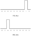
- frequency distribution and time-domain distribution of the modulation pulse signal loaded on the IM 1 are simulated by using digital information provided by a logical function chip.
- FIG. 4(a) an electrical pulse with specific frequency distribution and time-domain distribution is simulated through arrangement and distribution of digital information.
- This modulation pulse signal decides frequency distribution and time-domain distribution information of a modulated first local-frequency optical pulse signal.
- FIG. 4(b) by changing the arrangement and distribution of digital information, the time-domain distribution of the modulation pulse signal is changed. It can be learned from FIG. 4(a) and FIG. 4(b) that the electrical pulse generated in FIG. 4(a) has a delay in time relative to that generated in FIG.
- the first local-frequency optical pulse signal generated through chopping by the IM 1 has same frequency distribution and time-domain distribution as the optical pulse signal. Considering periodicity, this difference of FIG. 4(a) from FIG. 4(b) is equivalent that several digits "0" are added before a start point.
- a prerequisite for obtaining the modulation pulse signal by the receiving apparatus in this embodiment of this application is that a reference pulse signal is detected. Therefore, whatever kind of change occurs in a transmission optical path to cause an additional delay in transmission of the optical pulse signal does not impact alignment between the optical pulse signal and the first local-frequency optical pulse signal.
- timing alignment between the first local-frequency optical pulse signal and the optical pulse signal may be more efficiently completed.
- the signal receiving module 100 may further include a first beamsplitter 120 and a first detector 130. That the signal receiving module 100 is configured to detect the reference pulse signal in the received optical pulse signal includes: splitting, by the first beamsplitter 120, the received optical pulse signal, and detecting, by the first detector 130, a reference pulse signal in a separated optical pulse signal.
- the optical pulse signal includes the reference pulse signal and the quantum optical pulse signal.
- the first beamsplitter 120 performs light splitting processing for the received optical pulse signal, and detects, by using the first detector 130, the reference pulse signal in the optical pulse signal separated through the light splitting.
- the first detector 130 may be a classical photoelectric detector.
- Beamsplitting configuration of the first beamsplitter 120 needs to be properly selected based on a line attenuation condition of the SR-CV-QKD system. Because in the SR-CV-QKD system, a light intensity of the reference pulse signal may be approximately 1000 times that of the quantum optical pulse signal (the light intensity of the quantum optical pulse signal is approximately 10 photons per optical pulse), after a specific proportion is separated out by the first beamsplitter 120, it needs to be ensured that an intensity of a reference pulse signal in a separated optical pulse signal can still be detected by the classical photoelectric detector.
- the first beamsplitter 120 needs to ensure that additional attenuation generated by a quantum optical pulse signal in an optical pulse signal that is not separated is within a specified range, and this range is an acceptable range for the SR-CV-QKD system, otherwise the SR-CV-QKD system may not be able to generate a security key.
- the first beamsplitter 120 may be selected to be a 1:9 beamsplitter.
- a light intensity of the reference pulse signal in the separated optical pulse signal is still relatively high, and only 1 dB additional attenuation is introduced to a quantum optical pulse signal in the finally measured optical pulse signal. This is acceptable to the SR-CV-QKD system in a case of a short transmission distance.
- the first detector 130 is a photoelectrical detector.
- the first detector 130 detects reference pulse signals in the optical signal, to obtain each reference pulse signal that is converted into an electrical pulse signal.
- the first detector 130 detects the reference pulse signal in the optical pulse signal, because a light intensity of the quantum optical pulse signal in the optical pulse signal is extremely low, it may be considered that the first detector 130 cannot respond to the quantum optical pulse signal, and a corresponding electrical pulse signal cannot be generated either.
- the electrical pulse signal corresponding to the reference pulse signal can be obtained by using the optical pulse signal in the synchronization clock module 200, and frequency distribution and time-domain distribution of the optical pulse signal are consistent with frequency distribution and time-domain distribution of the reference pulse signal.
- the receiving apparatus may further include a signal modulation unit 140 and a second intensity modulator 150.
- the second intensity modulator 150 is connected to the signal modulation unit 140 and the synchronization clock module 200 separately; and the second intensity modulator IM 2 150 is connected to the first intensity modulator 110.
- the synchronization clock module 200 is further configured to determine timing information of the reference pulse signal, the signal modulation unit 140 is further configured to determine modulation information based on the timing information, and the second intensity modulator IM 2 150 is configured to adjust the first local-frequency optical pulse signal based on the modulation information.
- the synchronization clock module 200 obtains frequency information of the reference pulse signal and sends the frequency information to the signal modulation unit 140, so as to load modulation information to the second intensity modulator IM 2 150, where the modulation information is used to adjust an intensity of the first local-frequency optical pulse signal output from the first intensity modulator IM 1 to the second intensity modulator IM 2 150.
- the second intensity modulator IM 2 adjusts, based on the modulation information, the first local-frequency optical pulse signal into local-frequency optical pulses of two intensities: a second local-frequency optical pulse signal and a third local-frequency optical pulse signal.
- the second local-frequency optical pulse signal interferes with the quantum optical pulse signal
- the third local-frequency optical pulse signal interferes with the reference pulse signal, where an intensity of the second local-frequency optical pulse signal is greater than an intensity of the third local-frequency optical pulse signal.
- a local-frequency optical pulse signal with a higher intensity in the modulated local-frequency optical pulse signals of two intensities interferes with the received quantum optical pulse signal, and a local-frequency optical pulse signal with a lower intensity interferes with the received reference pulse signal.
- the signal receiving module may further include a balanced homodyne detector.
- An input end of the balanced homodyne detector is connected to a phase modulator PM by using a second beamsplitter in the signal receiving module 100, and the second beamsplitter is connected to the second intensity modulator IM 2 150.
- the balanced homodyne detector is used to perform detection, and a detection result of the balanced homodyne detector has a direct relationship with a square of a product of intensities of the two lines of interference light (namely, interference light between the local-frequency optical pulse signal with the higher intensity and the quantum optical pulse signal, and interference light between the local-frequency optical pulse signal with the lower intensity and the reference pulse signal).
- an intensity of the interference light corresponding to the reference pulse signal detected by the balanced homodyne detector is approximately 30 times different from an intensity of the interference light corresponding to the quantum optical pulse signal because the intensity of the reference pulse signal is approximately 1000 times that of the quantum optical pulse signal.
- an output range of the balanced homodyne detector is fixed and limited.
- measurement output of the reference pulse signal is not saturated, measurement output for the quantum optical pulse signal accounts for only less than 1/30 of the output range of the balanced homodyne detector.
- data sampling is performed by using an analog to digital converter A/D converter, or referred to as an ADC (analog to digital converter).
- ADC analog to digital converter
- a utilized dynamic AD/DA range is not reasonable. This imposes a specific impact on measurement accuracy of the quantum optical pulse signal.
- the quantum optical pulse signal is a carrier of key information, a best possible accurate measurement result for the signal is desired.
- local-frequency optical pulse signals of different intensities are used to interfere with the reference pulse signal and the quantum optical pulse signal in the optical pulse signal.
- a local-frequency optical pulse signal with an intensity I 1 interferes with the reference pulse signal
- a local-frequency optical pulse signal with an intensity I 2 interferes with the quantum optical pulse signal
- I 1 and I 2 have a relationship I 2 ⁇ 1000I 1 .
- the balanced homodyne detector is used to detect the reference pulse signal and the quantum optical pulse signal
- a detection result for the reference pulse signal is approximate to a detection result for the quantum optical pulse signal. Therefore, sampling for measurement output for the quantum optical pulse signal can make full use of the dynamic AD/DA range of the ADC, and a more accurate measurement result can be obtained.
- An extinction ratio of an intensity modulator using a current technology may be made to be approximately 30 dB.
- two local-frequency optical pulse signals whose intensities are different by approximately 1000 times can be modulated by using only one intensity modulator.
- one part of the local-frequency optical pulse signal interferes with the reference pulse signal in the optical pulse signal, and the other part of the local-frequency optical pulse signal interferes with the quantum optical pulse signal in the optical pulse signal.
- the second intensity modulator IM 2 is configured to: when the local-frequency optical pulse signal used to interfere with the reference pulse signal arrives, attenuate the local-frequency optical pulse signal, and when the local-frequency optical pulse signal interfering with the quantum optical pulse signal arrives, skip attenuating the local-frequency optical pulse signal.
- a rectangular wave signal may be loaded on the second intensity modulator IM 2 , and a frequency and a duty cycle of the rectangular wave signal are consistent with proportions of a frequency and a duty cycle of the quantum optical pulse signal in those of the entire optical pulse signal.
- the proportions of the frequency and the duty cycle of the quantum optical pulse signal in those of the entire optical pulse signal are complementary with proportions of a frequency and a duty cycle of the reference pulse signal in those of the entire optical pulse signal.
- the entire optical pulse signal includes a mixture of the reference pulse signal and the quantum optical pulse signal at a ratio 1:1.
- the frequency of the square wave signal is consistent with the frequency of the reference pulse signal, a duty circle of the square wave signal is 50%, and an amplitude of the square wave signal meets that a low level makes the IM 2 in a maximum attenuation state and that a high level makes the IM 2 in a maximum pass-through state.
- the frequency of the quantum optical pulse signal may be calculated based on a measured frequency of the reference pulse signal.
- a specific calculation method has been mentioned above and belongs to the prior art. For ease of description, details are not described herein again.
- the signal receiving module 100 may further include a second beamsplitter 160 and a second detector 170, and the second beamsplitter is connected to the second intensity modulator 150, the second detector 170, and a phase modulator 180 separately.
- the second beamsplitter 160 is configured to separate the second local-frequency optical pulse signal and the third local-frequency optical pulse signal.
- the second detector 170 is configured to detect an intensity of the second local-frequency optical pulse signal and an intensity of the third local-frequency optical pulse signal.
- An intensity of a local-frequency optical pulse signal affects a vacuum noise level, and the balanced homodyne is relevant to the intensity of the local-frequency optical pulse signal.
- the balanced homodyne detector to obtain signal loading information from the measurement result through demodulation, light intensity information of the local-frequency optical pulse signal is also needed.
- a combination of one beamsplitter and one detector combination is disposed at an output end of the IM 2 , to detect intensity information of the first local-frequency optical pulse signal, to be specific, the second local-frequency optical pulse signal and the third local-frequency optical pulse signal, modulated by the IM 2 .
- light intensity jitters of different local-frequency optical pulse signals can be monitored also by using one beamsplitter and one detector, and further a vacuum noise level is calibrated.
- the detected intensity information is fed back to a final digital signal processor (Digital Signal Processor, DSP) to provide parameters of signal pulse adjustment information to the balanced homodyne detector.
- DSP Digital Signal Processor
- the DSP is connected to the balanced homodyne detector as shown in FIG. 3 .
- the intensity of the local-frequency optical pulse signal may be adjusted by using the IM 2 , and optimum gain output can be implemented for the reference pulse signal and the quantum optical pulse signal by using one balanced detector.
- the ADC is used to collect detection data of the reference pulse signal and the quantum optical pulse signal, a utilized dynamic AD/DA range is relatively reasonable.
- local-frequency optical pulse signals of different intensities are used.
- impacts imposed by intensities of different local-frequency optical pulse signals on the SR-CV-QKD system are described mainly from aspects of security and detection performance.
- an intensity of the local-frequency light is an important parameter to calibrate a vacuum noise level and should remain constant, otherwise a security risk may occur (for example, the local-frequency optical pulse signal is attacked).
- the local-frequency optical pulse signal is locally generated by the receiving apparatus, it may be considered that there is no outside attack on the local-frequency optical pulse signal.
- the intensity of the local-frequency optical pulse signal is monitored in real time. Therefore, local-frequency optical pulse signals of two different intensities used in this embodiment of this application have no impact on system security.
- a vacuum noise level is proportional to an intensity of a local-frequency optical pulse signal.
- the vacuum noise level needs to be significantly higher than (usually at least 10 times higher than) the electrical noise level.
- a detection result for the quantum optical pulse signal can be distinguished from the detection output only in this way.
- local-frequency light of two intensities I 1 and I 2 are used, and there are also two corresponding vacuum noise levels N 01 and N 02 .
- the local-frequency optical pulse signal with the intensity I 2 is used to detect the quantum optical pulse signal.
- the intensity of the local-frequency optical pulse signal is higher and is corresponding to the higher vacuum noise level N 02 .
- the local-frequency optical pulse signal with the I 1 light intensity is weaker, and the corresponding vacuum noise level N 01 is lower, where N 02 ⁇ 1000N 01 .
- the reference pulse signal When the reference pulse signal is detected, its vacuum noise level is overwhelmed by its electrical noise.
- the reference pulse signal For the reference pulse signal, its light intensity is relatively high (10 3 to 10 4 photons per pulse), and its signal-to-noise ratio is relatively high. Provided that detection output for the reference pulse signal is high enough in comparison with the electrical noise level, measurement for the reference pulse signal is still feasible.
- the IM 1 in this embodiment of the present invention implements timing alignment between the first local-frequency optical pulse signal and the optical pulse signal in another manner
- adjustment of the intensity of the first local-frequency optical pulse signal may be implemented by using a self-referenced continuous-variable quantum key distribution adjusting system shown in FIG. 5 , to make full use of the dynamic AD/DA range of the ADC, and further to obtain a more accurate measurement result for the quantum optical pulse signal.
- the signal receiving module 100 may further include a third beamsplitter 175 and a polarization recognizer 180, where the third beamsplitter 175 is connected to the first beamsplitter 120 and the polarization recognizer 180, or in other words, the first beamsplitter 120 is connected to the polarization recognizer 180 by using the third beamsplitter 175.
- the third beamsplitter 175 is configured to receive the optical pulse signal separated by the first beamsplitter 120, and perform beamsplitting on the optical pulse signal.
- the polarization recognizer 180 is configured to detect polarization information of a reference pulse signal in an optical pulse signal separated by the third beamsplitter, and generate polarization adjustment information based on the polarization information.
- the signal receiving module 100 may further include a dynamic polarization controller (Dynamic Polarization Control, DPC) 190, where an input end of the dynamic polarization controller 190 is connected to an output end of the polarization recognizer 180 and an output end of the second intensity modulator 150, and an output end of the dynamic polarization controller 190 is connected to an input end of the second beamsplitter 160.
- DPC Dynamic Polarization Control
- the dynamic polarization controller 190 is configured to adjust polarization directions of the second local-frequency optical pulse signal and the third local-frequency optical pulse signal based on the polarization adjustment information, and output the second local-frequency optical pulse signal and the third local-frequency optical pulse signal whose polarization directions are adjusted, to the second beamsplitter 160.
- the dynamic polarization controller 190 is disposed behind the IM 2 , and after detecting the polarization information of the reference pulse signal in the optical pulse signal, the polarization recognizer 180 generates the corresponding polarization adjustment information and feeds back the polarization adjustment information to the dynamic polarization controller 190, to adjust the polarization of the local-frequency light modulated by the IM 2 , so that a polarization direction of the local-frequency optical pulse information is aligned with a polarization direction of the reference pulse signal, ensuring optimum interference between the local-frequency optical pulse signal and the reference pulse signal and optimum interference between the local-frequency optical pulse signal and the quantum optical pulse signal.
- disposing the dynamic polarization controller 190 in the optical path of the local-frequency optical pulse signal is intended to minimize additional attenuation of the optical pulse signal in the optical path of the optical pulse signal.
- Using the receiving apparatus provided in this embodiment of this application can make full use of the reference pulse signal in the optical pulse signal separated after beamsplitting, to obtain real-time polarization information of the reference pulse signal from the reference pulse signal, so that the polarization direction of the local-frequency optical pulse signal can be adjusted in real time. Further, it is ensured that when the local-frequency optical pulse signal interferes with the received optical pulse signal, polarization directions of the two signals are aligned, thereby achieving optimum interference.
- the receiving apparatus provided in the embodiments of this application has been described above, and a signal receiving method provided in the embodiments of this application is to be described below with reference to FIG. 7 .
- the receiving method is executed by the receiving apparatus provided in the embodiments of this application.
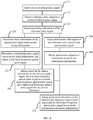
- FIG. 7 is a schematic flowchart of a signal receiving method according to an embodiment of this application. As shown in FIG. 7 , the receiving method may include the following steps.
- the receiving apparatus receives the optical pulse signal sent by a sending apparatus in an SR-CV-QKD system, where the optical pulse signal includes the reference pulse signal and a quantum optical pulse signal, and an intensity of the reference pulse signal is approximately 1000 times that of the quantum optical pulse signal.
- the receiving apparatus receives the optical pulse signal and detects the reference pulse signal in the optical pulse signal.
- the receiving apparatus generates the modulation pulse signal based on timing information of the detected reference pulse signal, where the timing information of the modulation pulse signal is consistent with timing information of the optical pulse signal.
- the modulation pulse signal is used to modulate a local-frequency optical pulse signal, that is, the first local-frequency optical pulse signal described in the embodiments of this application, so that the timing information of the modulated first local-frequency optical pulse signal is consistent with the timing information of the optical pulse signal, to be specific, frequency distribution and time-domain distribution of the first local-frequency optical pulse signal are consistent with frequency distribution and time-domain distribution of the optical pulse signal.
- the receiving apparatus obtains, through modulation based on the modulation pulse signal generated based on the timing information of the reference pulse signal, the first local-frequency optical pulse signal whose timing is consistent with that of the optical pulse signal, to efficiently implement timing alignment between the first local-frequency optical pulse signal and the optical pulse signal, so as to achieve optimum interference between the first local-frequency optical pulse signal and the optical pulse signal, and further achieve a more accurate raw key.
- the modulated first local-frequency optical pulse signal whose timing is consistent with that of the optical pulse signal is used to interfere with the reference pulse signal and the quantum optical pulse signal in the optical pulse signal, to obtain the raw key, and a quantum key is obtained after the receiving apparatus performs a series of processing on the obtained raw key.
- the reference pulse signal in the optical pulse signal is detected, the modulation pulse signal is obtained that can make the timing information (frequency distribution and time-domain distribution) of the first local-frequency optical pulse signal consistent with the timing information (frequency distribution and time-domain distribution) of the optical pulse signal, and then modulation is performed to make the timing information of the modulated first local-frequency optical pulse signal consistent with the timing information of the optical pulse signal, so that optimum interference can be achieved between the modulated first local-frequency optical pulse signal and the optical pulse signal, and a more accurate raw key is obtained.
- detecting the reference pulse signal in the received optical pulse signal includes the following steps.
- the received optical pulse signal may be split by using a first beamsplitter in the receiving apparatus, and the reference pulse signal in the optical pulse signal is detected by using a first detector connected to an output end of the first beamsplitter.
- a first beamsplitter in the receiving apparatus
- the reference pulse signal in the optical pulse signal is detected by using a first detector connected to an output end of the first beamsplitter.
- the optical pulse signal includes the reference pulse signal and the quantum optical pulse signal.
- determining the modulation pulse signal based on the reference pulse signal includes the following steps.
- processes of S221, S222, and S223 may be implemented by a synchronization receiving module in the receiving apparatus.
- the synchronization receiving module may include a clock recovery unit, and an input end of the clock recovery unit is connected to an output end of the first detector.
- the clock recovery unit recovers the timing information of the reference pulse signal, determines the clock information of the optical pulse signal based on a relationship existing between the reference pulse signal and the quantum optical pulse signal, and generates adjustment clock information based on the clock information of the optical pulse signal, so that the frequency distribution and time-domain distribution of the first local-frequency optical pulse signal are adjusted to be consistent with the frequency distribution and time-domain distribution of the optical pulse signal.
- the obtaining, based on the modulation pulse signal, a first local-frequency optical pulse signal having same timing as the optical pulse signal includes: chopping, by a first intensity modulator IM 1 in the receiving modulator based on the modulation pulse signal, continuous laser light generated by a laser, to form the first local-frequency optical pulse signal, where timing of the first local-frequency optical pulse signal obtained through chopping is consistent with timing of the optical pulse signal, that is, frequency distribution of the first local-frequency optical pulse signal is consistent with frequency distribution of the optical pulse signal, so that optimum interference is achieved between the first local-frequency optical pulse signal and the optical pulse signal, and a more accurate raw key is obtained.
- a first intensity modulator IM 1 in the receiving modulator based on the modulation pulse signal continuous laser light generated by a laser
- the receiving method may further include the following steps.
- the first local-frequency optical pulse signal may be adjusted by using a second intensity modulator IM 2 in the receiving apparatus.
- the IM2 adjusts, based on the timing information of the reference pulse signal, the first local-frequency optical pulse signal into local-frequency optical pulse signals of two intensities: a second local-frequency optical pulse signal and a third local-frequency optical pulse signal.
- a specific adjustment process refer to a process of adjusting, by the IM2, the first local-frequency optical pulse signal in FIG. 3 , and for brevity, details are not described herein again.
- the using the first local-frequency optical pulse signal to interfere with the reference pulse signal and the quantum optical pulse signal includes: using the second local-frequency optical pulse signal to interfere with the quantum optical pulse signal, and using the third local-frequency optical pulse signal to interfere with the reference pulse signal, where an intensity of the second local-frequency optical pulse signal is greater than an intensity of the third local-frequency optical pulse signal.
- the IM 2 adjusts the first local-frequency optical pulse signal into the local-frequency optical pulse signals of different intensities, the second local-frequency optical pulse signal and the third local-frequency optical pulse signal, detection may be performed by using one balanced homodyne detector, so that an intensity of the reference pulse signal is 1000 times that of the quantum optical pulse signal, and when detection for the reference pulse signal is not saturated, a dynamic AD/DA range for data collection of the quantum optical pulse is also reasonable.
- the receiving method may further include the following steps.
- S250 and S260 may be implemented by the polarization recognizer and the dynamic polarization controller shown in FIG 6 .
- For a specific implementation process refer to the described operation processes of the polarization recognizer and the dynamic polarization controller shown in FIG 6 , and for brevity of description, details are not described herein again.
- the method may further include the following step.
Landscapes
- Engineering & Computer Science (AREA)
- Physics & Mathematics (AREA)
- Electromagnetism (AREA)
- Computer Networks & Wireless Communication (AREA)
- Signal Processing (AREA)
- Computer Security & Cryptography (AREA)
- Optics & Photonics (AREA)
- Theoretical Computer Science (AREA)
- Condensed Matter Physics & Semiconductors (AREA)
- General Physics & Mathematics (AREA)
- Optical Communication System (AREA)
- Optical Modulation, Optical Deflection, Nonlinear Optics, Optical Demodulation, Optical Logic Elements (AREA)
Claims (15)
- Signalempfangsvorrichtung, wobei die Empfangsvorrichtung Folgendes umfasst:ein Signalempfangsmodul (100), das dazu ausgelegt ist, ein Referenzimpulssignal in einem empfangenen optischen Impulssignal zu detektieren, wobei das optische Impulssignal das Referenzimpulssignal und ein optisches Quantenimpulssignal umfasst; undein Synchronisationstaktmodul (200), das dazu ausgelegt ist, auf Basis des Referenzimpulssignals ein Modulationsimpulssignal zu empfangen; wobei ein erster Intensitätsmodulator (110) im Signalempfangsmodul (100) dazu ausgelegt ist, auf Basis des Modulationsimpulssignals ein erstes optisches lokales Frequenzimpulssignal, das dieselbe Taktung aufweist wie das optische Impulssignal, zu empfangen, und das Signalempfangsmodul des erste optische lokale Frequenzimpulssignal verwendet, um das Referenzimpulssignal und das optische Quantenimpulssignal separat zu beeinträchtigen, um einen rohen Schlüssel zu erhalten.
- Empfangsvorrichtung nach Anspruch 1, wobei das Signalempfangsmodul (100) einen ersten Strahlteiler (120) und einen ersten Detektor (130) umfasst, wobei der erste Strahlteiler dazu ausgelegt ist, das empfangene optische Impulssignal zu teilen; und
der erste Detektor (130) dazu ausgelegt ist, ein Referenzimpulssignal in einem separaten optischen Impulssignal zu detektieren. - Empfangsvorrichtung nach Anspruch 1 oder 2, wobei der erste Intensitätsmodulator (110) dazu ausgelegt ist, auf Basis des Modulationsimpulssignals das erste optische lokale Frequenzimpulssignal, das dieselbe Taktung wie das optische Impulssignal aufweist, zu empfangen, Folgendes umfasst:
Zerhacken von kontinuierlichem Laserlicht, das von einem Laser erzeugt wird, auf Basis des Modulationsimpulssignals durch den ersten Intensitätsmodulator (110), um das erste optische lokale Frequenzimpulssignal zu bilden. - Empfangsvorrichtung nach einem der Ansprüche 1 bis 3, wobei das Signalempfangsmodul (100) ferner eine Signalmodulationseinheit (140) und einen zweiten Intensitätsmodulator (150) umfasst; wobei der zweite Intensitätsmodulator (150) mit der ersten Signalmodulationseinheit (140) und dem ersten Intensitätsmodulator (110) verbunden ist;
das Synchronisationstaktmodul (200) ferner dazu ausgelegt ist, Taktungsinformationen des Referenzimpulssignals zu bestimmen;
die Signalmodulationseinheit (140) dazu ausgelegt ist, auf Basis der Taktungsinformationen Modulationsinformationen zu bestimmen; und
der zweite Intensitätsmodulator (150) dazu ausgelegt ist, das erste optische lokale Frequenzimpulssignal auf Basis der Modulationsinformationen zu optischen lokalen Frequenzimpulsen mit zwei Intensitäten anzupassen: einem zweiten optischen lokalen Frequenzimpulssignal und einem dritten optischen lokalen Frequenzimpulssignal. - Empfangsvorrichtung nach Anspruch 4, wobei das Signalempfangsmodul (100) das erste optische Impulssignal verwendet, um das Referenzimpulssignal und das optische Quantenimpulssignal separat zu beeinträchtigen, Folgendes umfasst:Verwenden des zweiten optischen lokalen Frequenzimpulssignals durch das Signalempfangsmodul (100), um das optische Quantenimpulssignal zu beeinträchtigen; undVerwenden des dritten optischen lokalen Frequenzimpulssignals durch das Signalempfangsmodul (100), um das Referenzimpulssignal zu beeinträchtigen; wobeieine Intensität des zweiten optischen lokalen Frequenzimpulssignals größer ist als eine Intensität des dritten optischen lokalen Frequenzimpulssignals.
- Empfangsvorrichtung nach Anspruch 4 oder 5, wobei das Signalempfangsmodul (100) ferner einen zweiten Strahlteiler (160) und einen zweiten Detektor (170) umfasst und der zweite Strahlteiler (160) mit dem zweiten Intensitätsmodulator (150), dem zweiten Detektor (170) und einem Phasenmodulator verbunden ist;
der zweite Strahlteiler (160) dazu ausgelegt ist, das zweite optische lokale Frequenzimpulssignal und das dritte optische lokale Frequenzimpulssignal zu trennen; und
der zweite Detektor (170) dazu ausgelegt ist, eine Intensität des zweiten optischen lokalen Frequenzimpulssignals und eine Intensität des dritten optischen lokalen Frequenzimpulssignals zu detektieren. - Empfangsvorrichtung nach einem der Ansprüche 4 bis 6, wobei das Signalempfangsmodul (100) einen dritten Strahlteiler (175) und einen Polarisationserkenner (180) umfasst und der erste Stromteiler (120) mit dem Polarisationserkenner (180) unter Verwendung des dritten Strahlteilers (175) verbunden ist;
der dritte Strahlteiler (175) dazu ausgelegt ist, das optische Impulssignal, das vom ersten Strahlteiler (120) getrennt wurde, zu empfangen und eine Strahlteilung am optischen Impulssignal durchzuführen; und
der Polarisationserkenner (180) zu Folgendem ausgelegt ist: Detektieren von Polarisationsinformationen des Referenzsignals im optischen Impulssignal und Erzeugen von Polarisationsanpassungsinformationen auf Basis der Polarisationsinformationen. - Empfangsvorrichtung nach Anspruch 7, wobei das Signalempfangsmodul (100) ferner eine dynamische Polarisationssteuerung (190) umfasst und die dynamische Polarisationssteuerung (190) mit dem Polarisationserkenner (180), dem zweiten Intensitätsmodulator (150) und dem zweiten Strahlteiler (160) verbunden ist; und
die dynamische Polarisationssteuerung (190) dazu ausgelegt ist, Polarisationsrichtungen des zweiten optischen lokalen Frequenzimpulssignals und des dritten optischen lokalen Frequenzimpulssignals auf Basis der Polarisationsanpassungsinformationen anzupassen und das zweite optische lokale Frequenzimpulssignal und das dritte optische lokale Frequenzimpulssignal, deren Polarisationsrichtungen angepasst wurden, zum zweiten Strahlteiler auszugeben. - Signalempfangsverfahren, wobei das Empfangsverfahren Folgendes umfasst:Detektieren eines Referenzimpulssignals in einem empfangenen optischen Impulssignal, wobei das optische Impulssignal das Referenzimpulssignal und ein optisches Quantenimpulssignal umfasst;Bestimmen eines Modulationsimpulssignals auf Basis des Referenzimpulssignals;Empfangen eines ersten optischen lokalen Frequenzimpulssignals, das dieselbe Taktung wie das optische Impulssignal aufweist, auf Basis des Modulationsimpulssignals;Verwenden des ersten optischen lokalen Frequenzimpulssignals, um das Referenzimpulssignal und das optische Quantenimpulssignal zu beeinträchtigen, um einen rohen Schlüssel zu erhalten.
- Empfangsverfahren nach Anspruch 9, wobei das Bestimmen eines Modulationsimpulssignals auf Basis des Referenzimpulssignals Folgendes umfasst:Bestimmen von Taktungsinformationen des Referenzimpulssignals;Bestimmen von Taktinformationen des optischen Impulssignals auf Basis der Taktungsinformationen; undBestimmen eines Modulationsimpulssignals auf Basis der Taktinformationen.
- Empfangsverfahren nach einem der Ansprüche 9 oder 10, wobei das Empfangen eines ersten optischen lokalen Frequenzimpulssignals, das dieselbe Taktung wie das optische Impulssignal aufweist, auf Basis des Modulationsimpulssignals Folgendes umfasst:
Zerhacken von kontinuierlichem Laserlicht, das von einem Laser erzeugt wird, auf Basis des Modulationsimpulssignals, um das erste optische lokale Frequenzimpulssignal zu bilden. - Empfangsverfahren nach Anspruch 10 oder 11, wobei das Verfahren ferner Folgendes umfasst:
Anpassen des ersten optischen lokalen Frequenzimpulssignals auf Basis der Taktungsinformationen zu optischen lokalen Frequenzimpulssignalen mit zwei Intensitäten: einem zweiten optischen lokalen Frequenzimpulssignal und einem dritten optischen lokalen Frequenzimpulssignal. - Empfangsverfahren nach Anspruch 12, wobei das Verwenden des ersten optischen lokalen Frequenzimpulssignals, um das Referenzimpulssignal und das optische Quantenimpulssignal zu beeinträchtigen, Folgendes umfasst:Verwenden des zweiten optischen lokalen Frequenzimpulssignals, um das optische Quantenimpulssignal zu beeinträchtigen; undVerwenden des dritten optischen lokalen Frequenzimpulssignals, um das Referenzimpulssignal zu beeinträchtigen; wobeieine Intensität des zweiten optischen lokalen Frequenzimpulssignals größer ist als eine Intensität des dritten optischen lokalen Frequenzimpulssignals.
- Empfangsverfahren nach einem der Ansprüche 9 bis 13, wobei das Verfahren ferner Folgendes umfasst:Detektieren von Polarisationsinformationen des Referenzimpulssignals im optischen Impulssignal; undErhalten von Polarisationsanpassungsinformationen auf Basis der Polarisationsinformationen.
- Verfahren nach Anspruch 14, wobei das Verfahren vor dem Verwenden des zweiten optischen lokalen Frequenzimpulssignals, um das optische Quantenimpulssignal zu beeinträchtigen, und Verwenden des dritten optischen lokalen Frequenzimpulssignals, um das Referenzimpulssignal zu beeinträchtigen, ferner Folgendes umfasst:
Anpassen von Polarisationsrichtungen des zweiten optischen lokalen Frequenzimpulssignals und des dritten optischen lokalen Frequenzimpulssignals auf Basis der Polarisationsanpassungsinformationen.
Applications Claiming Priority (2)
| Application Number | Priority Date | Filing Date | Title |
|---|---|---|---|
| CN201710271787.9A CN108737082B (zh) | 2017-04-24 | 2017-04-24 | 信号的接收装置和接收方法 |
| PCT/CN2018/082259 WO2018196585A1 (zh) | 2017-04-24 | 2018-04-09 | 信号的接收装置和接收方法 |
Publications (3)
| Publication Number | Publication Date |
|---|---|
| EP3588839A1 EP3588839A1 (de) | 2020-01-01 |
| EP3588839A4 EP3588839A4 (de) | 2020-03-25 |
| EP3588839B1 true EP3588839B1 (de) | 2021-05-19 |
Family
ID=63918827
Family Applications (1)
| Application Number | Title | Priority Date | Filing Date |
|---|---|---|---|
| EP18792163.0A Active EP3588839B1 (de) | 2017-04-24 | 2018-04-09 | Signalempfangsvorrichtung und empfangsverfahren |
Country Status (4)
| Country | Link |
|---|---|
| US (1) | US10749608B2 (de) |
| EP (1) | EP3588839B1 (de) |
| CN (1) | CN108737082B (de) |
| WO (1) | WO2018196585A1 (de) |
Families Citing this family (16)
| Publication number | Priority date | Publication date | Assignee | Title |
|---|---|---|---|---|
| CN109104251B (zh) * | 2017-06-20 | 2021-07-16 | 华为技术有限公司 | 一种数据传输方法、装置及系统 |
| CN111245599B (zh) * | 2018-11-28 | 2022-02-18 | 科大国盾量子技术股份有限公司 | 时域脉冲的延时控制装置以及量子密钥分发系统 |
| EP3664320A1 (de) * | 2018-12-05 | 2020-06-10 | Nederlandse Organisatie voor toegepast- natuurwetenschappelijk onderzoek TNO | Photonenaustauschbasiertes quantennetzwerk und verfahren zum betrieb solch eines netzwerks |
| CN111600657B (zh) * | 2019-02-21 | 2022-11-15 | 阿里巴巴集团控股有限公司 | 光信号发送与接收方法、设备、系统及数据中心网络 |
| CN109861709A (zh) * | 2019-03-25 | 2019-06-07 | 安徽问天量子科技股份有限公司 | 基于微波光子转换和平衡零拍探测的微波探测方法及微波接收机 |
| CN112787725B (zh) * | 2020-12-29 | 2022-04-08 | 武汉邮电科学研究院有限公司 | 一种qkd的信号产生装置及信号产生方法 |
| EP4295529B1 (de) * | 2021-02-16 | 2026-04-01 | Centre for Development of Telematics | Vorrichtung und verfahren zur einstellung der modulationssignalzeitreferenz eines phasenmodulators in einem quantenschlüsselverteilungssystem |
| CN113037473B (zh) * | 2021-03-01 | 2022-07-15 | 中南大学 | 基于硅光子集成芯片的cvqkd系统及方法 |
| CN115810972A (zh) * | 2021-09-13 | 2023-03-17 | 北京玻色量子科技有限公司 | 一种光量子计算装置 |
| CN114221758A (zh) * | 2021-11-29 | 2022-03-22 | 湖南大学 | 一种往返式双相位调制的量子密钥共享系统及方法 |
| CN115225246B (zh) * | 2022-07-11 | 2023-12-01 | 北京邮电大学 | 相位调制双向时间同步装置、方法和系统 |
| CN115167816B (zh) * | 2022-07-13 | 2024-08-13 | 国开启科量子技术(北京)有限公司 | 量子随机数生成控制方法及量子随机数生成装置 |
| JP2024048893A (ja) | 2022-09-28 | 2024-04-09 | 日本電気株式会社 | 量子暗号通信システム、その通信装置および通信制御方法 |
| CN116073996B (zh) * | 2023-01-18 | 2025-07-22 | 上海循态量子科技有限公司 | 连续变量量子密钥分发导频时延装置及方法 |
| CN115801254B (zh) * | 2023-02-07 | 2023-04-18 | 合肥硅臻芯片技术有限公司 | 量子密钥分发方法、发射端及量子密钥分发系统 |
| CN116125724B (zh) * | 2023-04-14 | 2023-06-16 | 合肥硅臻芯片技术有限公司 | 一种量子光脉冲产生装置及产生方法 |
Family Cites Families (28)
| Publication number | Priority date | Publication date | Assignee | Title |
|---|---|---|---|---|
| CN101176298B (zh) * | 2005-05-17 | 2011-03-30 | 朗迅科技公司 | 在多信道量子通信系统内的相位锁定 |
| JP2007251678A (ja) * | 2006-03-16 | 2007-09-27 | Sony Corp | 量子暗号通信装置および通信端末における平均光子数設定方法 |
| CN102916807B (zh) * | 2012-10-12 | 2015-05-20 | 上海交通大学 | 连续变量量子密钥分发系统的偏振补偿实现方法 |
| CN103414553B (zh) * | 2013-07-29 | 2016-04-06 | 南京发艾博光电科技有限公司 | 基于时隙交织主动偏振补偿的量子密钥分发系统及方法 |
| CN203368495U (zh) * | 2013-07-29 | 2013-12-25 | 南京发艾博光电科技有限公司 | 基于时隙交织主动偏振补偿的量子密钥分发系统 |
| CN104468093A (zh) * | 2013-09-18 | 2015-03-25 | 安徽量子通信技术有限公司 | 一种量子密钥分发系统的同步方法 |
| US9331875B2 (en) * | 2014-04-04 | 2016-05-03 | Nxgen Partners Ip, Llc | System and method for communication using orbital angular momentum with multiple layer overlay modulation |
| US9553677B1 (en) * | 2014-11-17 | 2017-01-24 | Sandia Corporation | Self-referenced continuous-variable quantum key distribution |
| WO2016099565A1 (en) * | 2014-12-19 | 2016-06-23 | Nokia Technologies Oy | Photonic chip for continuous variable quantum key distribution |
| US10891555B2 (en) * | 2018-08-07 | 2021-01-12 | Nxgen Partners Ip, Llc | Universal quantum computer, communication, QKD security and quantum networks using OAM Qu-dits with digital light processing |
| WO2017030532A1 (en) * | 2015-08-14 | 2017-02-23 | Nokia Technologies Oy | On-chip continuous variable quantum key distribution system with polarization and frequency division multiplexing |
| US9768885B2 (en) * | 2015-09-10 | 2017-09-19 | Ut-Battelle, Llc | Pilot-aided feedforward data recovery in optical coherent communications |
| CN106100837B (zh) * | 2015-10-23 | 2022-09-30 | 安徽问天量子科技股份有限公司 | 基于相同波长的全双工量子密钥分发系统的同步装置及方法 |
| EP3182638B1 (de) * | 2015-12-18 | 2019-12-25 | ID Quantique S.A. | Vorrichtung und verfahren zum hinzufügen einer entropiequelle zu quanten-schlüsselverteilungssystemen |
| EP3244566B1 (de) * | 2016-05-11 | 2020-08-05 | Institut Mines Telecom | Phasenreferenzteilungsschemata zur kontinuierlich-variablen quanten-kryptographie |
| CN105897413B (zh) * | 2016-05-26 | 2022-10-18 | 安徽问天量子科技股份有限公司 | 基于sagnac环的相位调制偏振编码的QKD系统 |
| CN205912067U (zh) * | 2016-05-26 | 2017-01-25 | 安徽问天量子科技股份有限公司 | 基于法拉第‑迈克尔逊干涉连续变量量子密钥分发系统 |
| US11502831B2 (en) * | 2016-09-09 | 2022-11-15 | Nec Corporation | Transmitting device, receiving device, quantum key distribution method, and quantum key distribution program for quantum key distribution system |
| CN107872314B (zh) * | 2016-09-27 | 2020-06-26 | 华为技术有限公司 | 编码装置、光反射器及基于其的量子密钥分发设备及系统 |
| EP3301851B1 (de) * | 2016-10-03 | 2020-12-23 | ID Quantique S.A. | Vorrichtung und verfahren für eine direkte quantum-kryptographie-system-implementierung über ein wdm-telekommunikationsnetz |
| CN106324613B (zh) * | 2016-10-19 | 2019-03-15 | 清华大学深圳研究生院 | 用于飞秒激光跟踪仪的数据采集与处理系统及方法 |
| EP3340529A1 (de) * | 2016-12-20 | 2018-06-27 | ID Quantique S.A. | Vorrichtung und verfahren zur verbesserung der geheimschlüsselaustauschrate über einen quantenkanal in quantenschlüsselverteilungssystemen |
| US10574448B2 (en) * | 2017-02-16 | 2020-02-25 | Nec Corporation | Multidimensional coded modulation for wireless communications with physical layer security |
| GB2559801B (en) * | 2017-02-20 | 2021-04-28 | Toshiba Kk | An optical quantum communication system |
| JP6934528B2 (ja) * | 2017-03-07 | 2021-09-15 | アイディー クアンティック エス.アー. | 量子暗号キー分配安定化装置 |
| CN106850217B (zh) * | 2017-04-06 | 2019-06-14 | 山西大学 | 一种实现一维调制连续变量量子密钥分发方法 |
| US10944553B2 (en) * | 2017-05-01 | 2021-03-09 | Ut-Battelle, Llc | Simultaneous classical and quantum communication scheme based on coherent detection |
| EP3399670B1 (de) * | 2017-05-03 | 2021-09-29 | Université de Genève | Vorrichtung und verfahren für decoy-zustand-drei-zustand-quantenschlüsselverteilung |
-
2017
- 2017-04-24 CN CN201710271787.9A patent/CN108737082B/zh active Active
-
2018
- 2018-04-09 EP EP18792163.0A patent/EP3588839B1/de active Active
- 2018-04-09 WO PCT/CN2018/082259 patent/WO2018196585A1/zh not_active Ceased
-
2019
- 2019-10-03 US US16/592,128 patent/US10749608B2/en active Active
Non-Patent Citations (1)
| Title |
|---|
| None * |
Also Published As
| Publication number | Publication date |
|---|---|
| WO2018196585A1 (zh) | 2018-11-01 |
| EP3588839A1 (de) | 2020-01-01 |
| EP3588839A4 (de) | 2020-03-25 |
| CN108737082A (zh) | 2018-11-02 |
| CN108737082B (zh) | 2020-11-17 |
| US20200044750A1 (en) | 2020-02-06 |
| US10749608B2 (en) | 2020-08-18 |
Similar Documents
| Publication | Publication Date | Title |
|---|---|---|
| US10749608B2 (en) | Signal receiving apparatus and method | |
| JP6602410B2 (ja) | 光量子通信システム | |
| Qi et al. | Experimental study on the Gaussian-modulated coherent-state quantum key distribution over standard telecommunication fibers | |
| US20200389299A1 (en) | Quantum security systems | |
| US8949300B2 (en) | Circuit and method for controlling quality of random numbers | |
| KR20190005868A (ko) | 연속 변수 퀀텀 암호화를 위한 위상 참조 공유 방식들 | |
| US20110280405A1 (en) | Systems and methods for stabilization of interferometers for quantum key distribution | |
| CN113328855B (zh) | 一种异步匹配的测量设备无关量子密钥分发方法及系统 | |
| WO2019149383A1 (en) | Quantum key distribution apparatus, system and method | |
| US8909048B2 (en) | Reflective optical networks | |
| US20170078029A1 (en) | Pilot-aided feedforward data recovery in optical coherent communications | |
| Tang et al. | Performance of continuous variable quantum key distribution system at different detector bandwidth | |
| Williams et al. | Field test of continuous-variable quantum key distribution with a true local oscillator | |
| CN109194470A (zh) | 高效连续变量量子密钥分发方法 | |
| Chandra et al. | FPGA-Based Synchronization of Frequency-Domain Interferometer for QKD | |
| EP4113897B1 (de) | Verfahren und system zur ausführung kohärenter optischer kommunikation unter verwendung einer kontinuierlich variablen quantenkryptographie und einer entfernten cv-laserquelle | |
| JP2015122675A (ja) | 変調装置および変調方法 | |
| Rajpurohit et al. | Advanced QKD Protocols and Practical Challenges | |
| JP2008259084A (ja) | 光通信システムにおける光強度設定方法および光通信装置 | |
| Gokul et al. | Experimental demonstration of coexistence of classical and quantum communication in quantum key distribution link | |
| e Silva et al. | Homodyne detection for quantum key distribution: an alternative to photon counting in BB84 protocol | |
| Gayathri et al. | Plug-n-Play Three Pulse Twin Field QKD | |
| Rutigliano et al. | High Security Optical Metropolitan Area Network based on Advanced Modulation Techniques | |
| EP4734435A1 (de) | Verfeinerte rauschschätzung in der kontinuierlich-variablen quantenkommunikation | |
| RU2776030C1 (ru) | Двухпроходная система фазовой модуляции для квантового распределения ключей |
Legal Events
| Date | Code | Title | Description |
|---|---|---|---|
| STAA | Information on the status of an ep patent application or granted ep patent |
Free format text: STATUS: THE INTERNATIONAL PUBLICATION HAS BEEN MADE |
|
| PUAI | Public reference made under article 153(3) epc to a published international application that has entered the european phase |
Free format text: ORIGINAL CODE: 0009012 |
|
| STAA | Information on the status of an ep patent application or granted ep patent |
Free format text: STATUS: REQUEST FOR EXAMINATION WAS MADE |
|
| 17P | Request for examination filed |
Effective date: 20190926 |
|
| AK | Designated contracting states |
Kind code of ref document: A1 Designated state(s): AL AT BE BG CH CY CZ DE DK EE ES FI FR GB GR HR HU IE IS IT LI LT LU LV MC MK MT NL NO PL PT RO RS SE SI SK SM TR |
|
| AX | Request for extension of the european patent |
Extension state: BA ME |
|
| A4 | Supplementary search report drawn up and despatched |
Effective date: 20200221 |
|
| RIC1 | Information provided on ipc code assigned before grant |
Ipc: H04L 9/08 20060101AFI20200217BHEP |
|
| DAV | Request for validation of the european patent (deleted) | ||
| DAX | Request for extension of the european patent (deleted) | ||
| GRAP | Despatch of communication of intention to grant a patent |
Free format text: ORIGINAL CODE: EPIDOSNIGR1 |
|
| STAA | Information on the status of an ep patent application or granted ep patent |
Free format text: STATUS: GRANT OF PATENT IS INTENDED |
|
| INTG | Intention to grant announced |
Effective date: 20201210 |
|
| GRAS | Grant fee paid |
Free format text: ORIGINAL CODE: EPIDOSNIGR3 |
|
| GRAA | (expected) grant |
Free format text: ORIGINAL CODE: 0009210 |
|
| STAA | Information on the status of an ep patent application or granted ep patent |
Free format text: STATUS: THE PATENT HAS BEEN GRANTED |
|
| AK | Designated contracting states |
Kind code of ref document: B1 Designated state(s): AL AT BE BG CH CY CZ DE DK EE ES FI FR GB GR HR HU IE IS IT LI LT LU LV MC MK MT NL NO PL PT RO RS SE SI SK SM TR |
|
| REG | Reference to a national code |
Ref country code: GB Ref legal event code: FG4D |
|
| REG | Reference to a national code |
Ref country code: CH Ref legal event code: EP |
|
| REG | Reference to a national code |
Ref country code: DE Ref legal event code: R096 Ref document number: 602018017442 Country of ref document: DE |
|
| REG | Reference to a national code |
Ref country code: AT Ref legal event code: REF Ref document number: 1395053 Country of ref document: AT Kind code of ref document: T Effective date: 20210615 |
|
| REG | Reference to a national code |
Ref country code: IE Ref legal event code: FG4D |
|
| REG | Reference to a national code |
Ref country code: LT Ref legal event code: MG9D |
|
| REG | Reference to a national code |
Ref country code: AT Ref legal event code: MK05 Ref document number: 1395053 Country of ref document: AT Kind code of ref document: T Effective date: 20210519 |
|
| REG | Reference to a national code |
Ref country code: NL Ref legal event code: MP Effective date: 20210519 |
|
| PG25 | Lapsed in a contracting state [announced via postgrant information from national office to epo] |
Ref country code: AT Free format text: LAPSE BECAUSE OF FAILURE TO SUBMIT A TRANSLATION OF THE DESCRIPTION OR TO PAY THE FEE WITHIN THE PRESCRIBED TIME-LIMIT Effective date: 20210519 Ref country code: BG Free format text: LAPSE BECAUSE OF FAILURE TO SUBMIT A TRANSLATION OF THE DESCRIPTION OR TO PAY THE FEE WITHIN THE PRESCRIBED TIME-LIMIT Effective date: 20210819 Ref country code: FI Free format text: LAPSE BECAUSE OF FAILURE TO SUBMIT A TRANSLATION OF THE DESCRIPTION OR TO PAY THE FEE WITHIN THE PRESCRIBED TIME-LIMIT Effective date: 20210519 Ref country code: LT Free format text: LAPSE BECAUSE OF FAILURE TO SUBMIT A TRANSLATION OF THE DESCRIPTION OR TO PAY THE FEE WITHIN THE PRESCRIBED TIME-LIMIT Effective date: 20210519 Ref country code: HR Free format text: LAPSE BECAUSE OF FAILURE TO SUBMIT A TRANSLATION OF THE DESCRIPTION OR TO PAY THE FEE WITHIN THE PRESCRIBED TIME-LIMIT Effective date: 20210519 |
|
| PG25 | Lapsed in a contracting state [announced via postgrant information from national office to epo] |
Ref country code: LV Free format text: LAPSE BECAUSE OF FAILURE TO SUBMIT A TRANSLATION OF THE DESCRIPTION OR TO PAY THE FEE WITHIN THE PRESCRIBED TIME-LIMIT Effective date: 20210519 Ref country code: PL Free format text: LAPSE BECAUSE OF FAILURE TO SUBMIT A TRANSLATION OF THE DESCRIPTION OR TO PAY THE FEE WITHIN THE PRESCRIBED TIME-LIMIT Effective date: 20210519 Ref country code: NO Free format text: LAPSE BECAUSE OF FAILURE TO SUBMIT A TRANSLATION OF THE DESCRIPTION OR TO PAY THE FEE WITHIN THE PRESCRIBED TIME-LIMIT Effective date: 20210819 Ref country code: SE Free format text: LAPSE BECAUSE OF FAILURE TO SUBMIT A TRANSLATION OF THE DESCRIPTION OR TO PAY THE FEE WITHIN THE PRESCRIBED TIME-LIMIT Effective date: 20210519 Ref country code: RS Free format text: LAPSE BECAUSE OF FAILURE TO SUBMIT A TRANSLATION OF THE DESCRIPTION OR TO PAY THE FEE WITHIN THE PRESCRIBED TIME-LIMIT Effective date: 20210519 Ref country code: PT Free format text: LAPSE BECAUSE OF FAILURE TO SUBMIT A TRANSLATION OF THE DESCRIPTION OR TO PAY THE FEE WITHIN THE PRESCRIBED TIME-LIMIT Effective date: 20210920 Ref country code: IS Free format text: LAPSE BECAUSE OF FAILURE TO SUBMIT A TRANSLATION OF THE DESCRIPTION OR TO PAY THE FEE WITHIN THE PRESCRIBED TIME-LIMIT Effective date: 20210919 Ref country code: GR Free format text: LAPSE BECAUSE OF FAILURE TO SUBMIT A TRANSLATION OF THE DESCRIPTION OR TO PAY THE FEE WITHIN THE PRESCRIBED TIME-LIMIT Effective date: 20210820 |
|
| PG25 | Lapsed in a contracting state [announced via postgrant information from national office to epo] |
Ref country code: NL Free format text: LAPSE BECAUSE OF FAILURE TO SUBMIT A TRANSLATION OF THE DESCRIPTION OR TO PAY THE FEE WITHIN THE PRESCRIBED TIME-LIMIT Effective date: 20210519 |
|
| PG25 | Lapsed in a contracting state [announced via postgrant information from national office to epo] |
Ref country code: CZ Free format text: LAPSE BECAUSE OF FAILURE TO SUBMIT A TRANSLATION OF THE DESCRIPTION OR TO PAY THE FEE WITHIN THE PRESCRIBED TIME-LIMIT Effective date: 20210519 Ref country code: DK Free format text: LAPSE BECAUSE OF FAILURE TO SUBMIT A TRANSLATION OF THE DESCRIPTION OR TO PAY THE FEE WITHIN THE PRESCRIBED TIME-LIMIT Effective date: 20210519 Ref country code: RO Free format text: LAPSE BECAUSE OF FAILURE TO SUBMIT A TRANSLATION OF THE DESCRIPTION OR TO PAY THE FEE WITHIN THE PRESCRIBED TIME-LIMIT Effective date: 20210519 Ref country code: SM Free format text: LAPSE BECAUSE OF FAILURE TO SUBMIT A TRANSLATION OF THE DESCRIPTION OR TO PAY THE FEE WITHIN THE PRESCRIBED TIME-LIMIT Effective date: 20210519 Ref country code: ES Free format text: LAPSE BECAUSE OF FAILURE TO SUBMIT A TRANSLATION OF THE DESCRIPTION OR TO PAY THE FEE WITHIN THE PRESCRIBED TIME-LIMIT Effective date: 20210519 Ref country code: EE Free format text: LAPSE BECAUSE OF FAILURE TO SUBMIT A TRANSLATION OF THE DESCRIPTION OR TO PAY THE FEE WITHIN THE PRESCRIBED TIME-LIMIT Effective date: 20210519 Ref country code: SK Free format text: LAPSE BECAUSE OF FAILURE TO SUBMIT A TRANSLATION OF THE DESCRIPTION OR TO PAY THE FEE WITHIN THE PRESCRIBED TIME-LIMIT Effective date: 20210519 |
|
| REG | Reference to a national code |
Ref country code: DE Ref legal event code: R097 Ref document number: 602018017442 Country of ref document: DE |
|
| PLBE | No opposition filed within time limit |
Free format text: ORIGINAL CODE: 0009261 |
|
| STAA | Information on the status of an ep patent application or granted ep patent |
Free format text: STATUS: NO OPPOSITION FILED WITHIN TIME LIMIT |
|
| 26N | No opposition filed |
Effective date: 20220222 |
|
| PG25 | Lapsed in a contracting state [announced via postgrant information from national office to epo] |
Ref country code: IS Free format text: LAPSE BECAUSE OF FAILURE TO SUBMIT A TRANSLATION OF THE DESCRIPTION OR TO PAY THE FEE WITHIN THE PRESCRIBED TIME-LIMIT Effective date: 20210919 Ref country code: AL Free format text: LAPSE BECAUSE OF FAILURE TO SUBMIT A TRANSLATION OF THE DESCRIPTION OR TO PAY THE FEE WITHIN THE PRESCRIBED TIME-LIMIT Effective date: 20210519 |
|
| PG25 | Lapsed in a contracting state [announced via postgrant information from national office to epo] |
Ref country code: IT Free format text: LAPSE BECAUSE OF FAILURE TO SUBMIT A TRANSLATION OF THE DESCRIPTION OR TO PAY THE FEE WITHIN THE PRESCRIBED TIME-LIMIT Effective date: 20210519 |
|
| REG | Reference to a national code |
Ref country code: CH Ref legal event code: PL |
|
| GBPC | Gb: european patent ceased through non-payment of renewal fee |
Effective date: 20220409 |
|
| REG | Reference to a national code |
Ref country code: BE Ref legal event code: MM Effective date: 20220430 |
|
| PG25 | Lapsed in a contracting state [announced via postgrant information from national office to epo] |
Ref country code: MC Free format text: LAPSE BECAUSE OF FAILURE TO SUBMIT A TRANSLATION OF THE DESCRIPTION OR TO PAY THE FEE WITHIN THE PRESCRIBED TIME-LIMIT Effective date: 20210519 Ref country code: LU Free format text: LAPSE BECAUSE OF NON-PAYMENT OF DUE FEES Effective date: 20220409 Ref country code: LI Free format text: LAPSE BECAUSE OF NON-PAYMENT OF DUE FEES Effective date: 20220430 Ref country code: GB Free format text: LAPSE BECAUSE OF NON-PAYMENT OF DUE FEES Effective date: 20220409 Ref country code: FR Free format text: LAPSE BECAUSE OF NON-PAYMENT OF DUE FEES Effective date: 20220430 Ref country code: CH Free format text: LAPSE BECAUSE OF NON-PAYMENT OF DUE FEES Effective date: 20220430 |
|
| PG25 | Lapsed in a contracting state [announced via postgrant information from national office to epo] |
Ref country code: BE Free format text: LAPSE BECAUSE OF NON-PAYMENT OF DUE FEES Effective date: 20220430 |
|
| PG25 | Lapsed in a contracting state [announced via postgrant information from national office to epo] |
Ref country code: IE Free format text: LAPSE BECAUSE OF NON-PAYMENT OF DUE FEES Effective date: 20220409 |
|
| P01 | Opt-out of the competence of the unified patent court (upc) registered |
Effective date: 20230524 |
|
| PG25 | Lapsed in a contracting state [announced via postgrant information from national office to epo] |
Ref country code: MK Free format text: LAPSE BECAUSE OF FAILURE TO SUBMIT A TRANSLATION OF THE DESCRIPTION OR TO PAY THE FEE WITHIN THE PRESCRIBED TIME-LIMIT Effective date: 20210519 Ref country code: CY Free format text: LAPSE BECAUSE OF FAILURE TO SUBMIT A TRANSLATION OF THE DESCRIPTION OR TO PAY THE FEE WITHIN THE PRESCRIBED TIME-LIMIT Effective date: 20210519 |
|
| PG25 | Lapsed in a contracting state [announced via postgrant information from national office to epo] |
Ref country code: HU Free format text: LAPSE BECAUSE OF FAILURE TO SUBMIT A TRANSLATION OF THE DESCRIPTION OR TO PAY THE FEE WITHIN THE PRESCRIBED TIME-LIMIT; INVALID AB INITIO Effective date: 20180409 |
|
| PG25 | Lapsed in a contracting state [announced via postgrant information from national office to epo] |
Ref country code: TR Free format text: LAPSE BECAUSE OF FAILURE TO SUBMIT A TRANSLATION OF THE DESCRIPTION OR TO PAY THE FEE WITHIN THE PRESCRIBED TIME-LIMIT Effective date: 20210519 |
|
| PG25 | Lapsed in a contracting state [announced via postgrant information from national office to epo] |
Ref country code: MT Free format text: LAPSE BECAUSE OF FAILURE TO SUBMIT A TRANSLATION OF THE DESCRIPTION OR TO PAY THE FEE WITHIN THE PRESCRIBED TIME-LIMIT Effective date: 20210519 |
|
| PGFP | Annual fee paid to national office [announced via postgrant information from national office to epo] |
Ref country code: DE Payment date: 20250305 Year of fee payment: 8 |