EP3587847A1 - Conical roller bearing - Google Patents
Conical roller bearing Download PDFInfo
- Publication number
- EP3587847A1 EP3587847A1 EP18757785.3A EP18757785A EP3587847A1 EP 3587847 A1 EP3587847 A1 EP 3587847A1 EP 18757785 A EP18757785 A EP 18757785A EP 3587847 A1 EP3587847 A1 EP 3587847A1
- Authority
- EP
- European Patent Office
- Prior art keywords
- flange surface
- large flange
- roughness
- roller
- tapered roller
- Prior art date
- Legal status (The legal status is an assumption and is not a legal conclusion. Google has not performed a legal analysis and makes no representation as to the accuracy of the status listed.)
- Granted
Links
Images




Classifications
-
- F—MECHANICAL ENGINEERING; LIGHTING; HEATING; WEAPONS; BLASTING
- F16—ENGINEERING ELEMENTS AND UNITS; GENERAL MEASURES FOR PRODUCING AND MAINTAINING EFFECTIVE FUNCTIONING OF MACHINES OR INSTALLATIONS; THERMAL INSULATION IN GENERAL
- F16C—SHAFTS; FLEXIBLE SHAFTS; ELEMENTS OR CRANKSHAFT MECHANISMS; ROTARY BODIES OTHER THAN GEARING ELEMENTS; BEARINGS
- F16C19/00—Bearings with rolling contact, for exclusively rotary movement
- F16C19/22—Bearings with rolling contact, for exclusively rotary movement with bearing rollers essentially of the same size in one or more circular rows, e.g. needle bearings
- F16C19/34—Bearings with rolling contact, for exclusively rotary movement with bearing rollers essentially of the same size in one or more circular rows, e.g. needle bearings for both radial and axial load
- F16C19/36—Bearings with rolling contact, for exclusively rotary movement with bearing rollers essentially of the same size in one or more circular rows, e.g. needle bearings for both radial and axial load with a single row of rollers
- F16C19/364—Bearings with rolling contact, for exclusively rotary movement with bearing rollers essentially of the same size in one or more circular rows, e.g. needle bearings for both radial and axial load with a single row of rollers with tapered rollers, i.e. rollers having essentially the shape of a truncated cone
-
- F—MECHANICAL ENGINEERING; LIGHTING; HEATING; WEAPONS; BLASTING
- F16—ENGINEERING ELEMENTS AND UNITS; GENERAL MEASURES FOR PRODUCING AND MAINTAINING EFFECTIVE FUNCTIONING OF MACHINES OR INSTALLATIONS; THERMAL INSULATION IN GENERAL
- F16C—SHAFTS; FLEXIBLE SHAFTS; ELEMENTS OR CRANKSHAFT MECHANISMS; ROTARY BODIES OTHER THAN GEARING ELEMENTS; BEARINGS
- F16C33/00—Parts of bearings; Special methods for making bearings or parts thereof
- F16C33/30—Parts of ball or roller bearings
- F16C33/34—Rollers; Needles
- F16C33/36—Rollers; Needles with bearing-surfaces other than cylindrical, e.g. tapered; with grooves in the bearing surfaces
- F16C33/366—Tapered rollers, i.e. rollers generally shaped as truncated cones
-
- F—MECHANICAL ENGINEERING; LIGHTING; HEATING; WEAPONS; BLASTING
- F16—ENGINEERING ELEMENTS AND UNITS; GENERAL MEASURES FOR PRODUCING AND MAINTAINING EFFECTIVE FUNCTIONING OF MACHINES OR INSTALLATIONS; THERMAL INSULATION IN GENERAL
- F16C—SHAFTS; FLEXIBLE SHAFTS; ELEMENTS OR CRANKSHAFT MECHANISMS; ROTARY BODIES OTHER THAN GEARING ELEMENTS; BEARINGS
- F16C33/00—Parts of bearings; Special methods for making bearings or parts thereof
- F16C33/30—Parts of ball or roller bearings
- F16C33/58—Raceways; Race rings
- F16C33/583—Details of specific parts of races
- F16C33/585—Details of specific parts of races of raceways, e.g. ribs to guide the rollers
-
- F—MECHANICAL ENGINEERING; LIGHTING; HEATING; WEAPONS; BLASTING
- F16—ENGINEERING ELEMENTS AND UNITS; GENERAL MEASURES FOR PRODUCING AND MAINTAINING EFFECTIVE FUNCTIONING OF MACHINES OR INSTALLATIONS; THERMAL INSULATION IN GENERAL
- F16C—SHAFTS; FLEXIBLE SHAFTS; ELEMENTS OR CRANKSHAFT MECHANISMS; ROTARY BODIES OTHER THAN GEARING ELEMENTS; BEARINGS
- F16C2240/00—Specified values or numerical ranges of parameters; Relations between them
- F16C2240/40—Linear dimensions, e.g. length, radius, thickness, gap
- F16C2240/54—Surface roughness
Definitions
- the present invention relates to a tapered roller bearing.
- the roller large end surfaces of the tapered rollers come into sliding contact with the large flange surface of the inner ring.
- the surface roughness of the large flange surface is adjusted such that a sufficient oil film is formed between the roller large end surfaces and the large flange surface.
- a preload is applied to the tapered roller bearing for the purpose of improving the rigidity and rotation accuracy of the tapered roller bearing.
- it is necessary to determine an appropriate amount of the preload by measuring the rotation torque of the tapered roller bearing.
- the rotation torque is measured while rotating the tapered roller bearing at a low speed (normally 100 r/min or less), for the convenience of the step of mounting the tapered roller bearing to a device.
- the rotation torque of the tapered roller bearing is generated mainly by the sliding friction between the roller large end surfaces of the tapered rollers and the large flange surface of the inner ring, and is affected only to a very small degree by the rolling friction generated between the tapered rollers and the inner and outer rings. Therefore, in order to accurately measure the rotation torque of the tapered roller bearing, it is necessary to fully break in the tapered roller bearing at a low rotation speed, while applying a preload to the tapered roller bearing until the roller large end surfaces of the tapered rollers come into contact with the large flange surface of the inner ring (i.e., until the width dimension of the bearing is stabilized).
- Patent Document 1 discloses a tapered roller bearing in which the surface roughness Ra of the large flange surface of the inner ring is set within the range of 0.05 to 0.20 ⁇ m so as to maintain appropriate lubrication condition between the large flange surface of the inner ring and the roller large end surfaces of the tapered rollers.
- the surface roughness Ra of the large flange surface is less than 0.05 ⁇ m
- the lubrication condition between the large flange surface of the inner ring and the roller large end surfaces of the tapered rollers becomes mixed lubrication which is a mixed state of fluid lubrication and boundary lubrication.
- the friction coefficient fluctuates to a large degree, and thus the measured rotation torque also fluctuates to a large degree, thereby making it difficult to accurately manage the preload.
- the surface roughness Ra of the large flange surface is 0.05 ⁇ m or more, the lubrication condition between the large flange surface and the roller large end surfaces becomes boundary lubrication.
- the friction coefficient is stabilized, thereby making it possible to accurately manage the preload.
- a sufficient oil film is formed between the large flange surface and the roller large end surfaces, so that the lubrication condition between the large flange surface and the roller large end surfaces becomes fluid lubrication, and thus the friction coefficient is small.
- the surface roughness Ra of the large flange surface is more than 0.20 ⁇ m, when the temperature of the bearing rises in the high-speed rotation range, and the viscosity of lubricating oil decreases, an oil film having a sufficient thickness is not formed between the large flange surface and the roller large end surfaces. This may generate seizure between the roller large end surfaces and the large flange surface.
- Patent Document 2 discloses a tapered roller bearing in which the surface roughness Ra of each of the roller large end surfaces of the tapered rollers is set to be 0.1 ⁇ m or less, and the surface roughness Ra of the large flange surface of the inner ring is set to be 0.2 ⁇ m or less, thereby improving the stability of rotation torque when the bearing is broken in.
- the present invention provides a tapered roller bearing comprising: tapered rollers each having a roller large end surface; and an inner ring having a large flange surface configured to come into sliding contact with the roller large end surfaces of the tapered rollers, characterized in that the large flange surface has: an arithmetic mean roughness Ra of 0.1 ⁇ m ⁇ Ra ⁇ 0.2 ⁇ m; a roughness curve skewness Rsk of -1.0 ⁇ Rsk ⁇ -0.3; and a roughness curve kurtosis Rku of 3.0 ⁇ Rku ⁇ 5.0.
- the arithmetic mean roughness Ra, the roughness curve skewness Rsk, and the roughness curve kurtosis Rku according to the present invention are stipulated in B0601:2013 of the Japanese Industrial Standards (JIS).
- the large flange surface of the inner ring is within the range of 0.1 to 0.2 ⁇ m
- the large flange surface is suitable for stabilizing rotation torque while the tapered roller bearing is rotating at a low speed, i.e., within the range of 0 to 200 (r/min).
- the large flange surface of which only the arithmetic mean roughness Ra is adjusted in this manner will be inferior in seizure resistance to a surface having a roughness of the super-finished level. Therefore, according to the present invention, the roughness curve skewness Rsk and the roughness curve kurtosis Rku of the large flange surface are also adjusted in the following manner.
- the roughness curve skewness Rsk is Rsk ⁇ 0, i.e., within a negative numerical value range, this means that a larger portion of the roughness curve is located above the average line, which in turn means that a greater area of the large flange surface forms a flat surface, so that an oil film can be formed in a reliable manner.
- the roughness curve skewness Rsk of the large-diameter flange surface is set within the range of -1.0 to -0.3.
- the roughness curve kurtosis Rku is less than 3.0, the distribution curve of protrusions and recesses distributed on the large flange surface has a flattened shape.
- the roughness curve kurtosis Rku is set within the range of 3.0 to 5.0.
- the roller large end surface of each of the tapered rollers has an arithmetic mean roughness Ra of 0.1 ⁇ m or less. Since bearing functions are less affected by the surface roughnesses of the roller large end surfaces than by the surface roughness of the large flange surface of the inner ring, the surface roughness of each of the roller large end surfaces may be managed based solely on the arithmetic mean roughness Ra, and not based on the skewness Rsk and kurtosis Rku.
- the large flange surface has one of: a shape generated by a straight generatrix; a shape generated by a concave generatrix having a maximum depth of 1 ⁇ m or less at a mid-portion thereof; and a shape generated by a convex generatrix having a maximum height of 1 ⁇ m or less at a mid-portion thereof.
- the contact between the roller large end surfaces and the large flange surface is ideally the contact between spherical surfaces and a flat surface, because this can realize particularly excellent seizure resistance between the roller large end surfaces and the large flange surface. Therefore, the large flange surface is preferably generated by a substantially straight generatrix within the industrially feasible range.
- the large flange surface is generated by a concave generatrix recessed toward its center, or by a convex generatrix bulging toward its center, its maximum height or depth has to be limited to 1 ⁇ m, because otherwise, it is impossible to ensure an excellent wedge effect of lubricating oil.
- the tapered roller bearing according to the present invention is suitable for use in power transmission devices of an automobile, such as a differential and a transmission, which constitute the power transmission path through which motive power is transmitted from the driving source of the automobile to wheels.
- tapered roller bearing of the present invention has a structure as described above, it is possible to realize both stable rotation torque while the bearing is rotating at a low speed, and excellent seizure resistance between the large flange surface and the roller large end surfaces.
- a tapered roller bearing 1 embodying the present invention is now described with reference to Figs. 1 and 2 of the attached drawings.
- the tapered roller bearing 1 includes an inner ring 10, an outer ring 20, a plurality of tapered rollers 30, and a cage 40 retaining the tapered rollers 30.
- the inner ring 10, the outer ring 20 and the tapered rollers 30 are made of steel.
- the inner ring 10 and the outer ring 20 are annular bearing parts arranged coaxially with each other.
- the inner ring 10 has a raceway 11 on its outer periphery, and a large flange surface 12.
- the outer ring 20 has a raceway 21 on its inner periphery.
- the raceways 11 and 21 comprise conical surfaces.
- Each tapered roller 30 has a conical rolling surface 31, a roller small end surface 32, and a roller large end surface 33.
- the rolling surface 31 is disposed between the raceway 11 of the inner ring 10 and the raceway 21 of the outer ring 20.
- the roller small end surface 32 is the side surface of the tapered roller 30 at its small-diameter end.
- the roller large end surface 33 is the side surface of the tapered roller 30 at its large-diameter end.
- the roller large end surface 33 is a spherical surface.
- the surface roughnesses of the roller large end surfaces 33 of the tapered rollers 30 have a lesser influence on the seizure resistance and other bearing functions than the surface roughness of the large flange surface 12 of the inner ring 10. Therefore, the surface roughness of the roller large end surface 33 of each tapered roller 30 may be managed simply based on the arithmetic mean roughness Ra.
- the arithmetic mean roughness Ra of the roller large end surface 33 is set to be 0.1 ⁇ m or less.
- JIS Japanese Industrial Standards
- the large flange surface 12 of the inner ring 10 comes into sliding contact with the roller large end surfaces 33 of the tapered rollers 30. That is, the large flange surface 12 of the inner ring 10 is a portion of the surface of the inner ring that can come into sliding contact with the roller large end surfaces 33 of the tapered rollers 30 while the bearing is rotating.
- the large flange surface 12 has a shape generated by a straight generatrix (i.e., a conical shape).
- the large flange surface 12 may have a shape generated by a concave generatrix having a maximum depth ⁇ 1 of 1 ⁇ m or less at its mid-portion, as illustrated in Fig. 3 , or a shape generated by a convex generatrix having a maximum height ⁇ 1 of 1 ⁇ m or less at its mid-portion, as illustrated in Fig. 4 .
- the concave generatrix is gradually recessed in the direction away from the roller large end surface 33, from both ends p1 and p2 of the concave generatrix toward the center of the straight reference line (see the dashed line in Fig. 3 ) connecting both ends p1 and p2 of the concave generatrix defining the large flange surface 12.
- the convex generatrix gradually bulges toward the roller large end surface 33, from both ends p1 and p2 of the convex generatrix toward the center of the imaginary straight reference line (see the dashed line in Fig. 4 ) connecting both ends p1 and p2 of the convex generatrix.
- the contact between the roller large end surfaces 33 and the large flange surface 12 will be the contact between spherical surfaces and a flat surface, or a contact very similar to this. This ensures an excellent wedge effect of lubricating oil between the' roller large end surfaces 33 and the large flange surface 12.
- the large flange surface 12 has an arithmetic mean roughness Ra of 0.1 ⁇ m ⁇ Ra ⁇ 0.2 ⁇ m.
- the large flange surface 12 is capable of stabilizing rotation torque while the tapered roller bearing 1, shown in Fig. 1 , is rotating at a low speed, i.e., within the range of 0 to 200 (r/min).
- the large flange surface 12 has a roughness curve skewness Rsk of -1.0 ⁇ Rsk ⁇ -0.3.
- the roughness curve skewness Rsk is the mean of the cubes of Z(x) values within a reference length of a surface to be evaluated, made dimensionless by the cube of the root mean square roughness Rq of the profile curve.
- the roughness curve skewness Rsk is a numerical value indicative of the degree of asymmetry of the probability density function of the contour curve, and is a parameter strongly affected by protruding peaks and valleys of the profile curve.
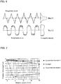
- Fig. 5 exemplifies a roughness curve satisfying the relation skewness Rsk > 0, and a roughness curve satisfying the relation skewness Rsk ⁇ 0.
- the large flange surface 12 is practically a flat surface, so that an oil film can be formed reliably thereon.
- the large flange surface 12 has a roughness curve kurtosis Rku of 3.0 ⁇ Rku ⁇ 5.0.
- the term "roughness curve kurtosis Rku”, as used herein, refers to the roughness curve kurtosis Rku stipulated in 4.2.4 of B0601:2013 of the Japanese Industrial Standards (JIS), and defined by the following formula 2. [Formula 2] Rku 1 Rq 4 1 lr ⁇ 0 lr Z 4 x dx
- the roughness curve kurtosis Rku is the mean of the fourth powers of Z(x) values within a reference length of a surface to be evaluated, made dimensionless by the fourth power of the root mean square roughness Rq of the profile curve.
- the roughness curve kurtosis Rku is a numerical value indicative of the degree of peakedness (steepness) of the probability density function of the contour curve, and is a parameter strongly affected by protruding peaks and valleys of the profile curve.
- Fig. 6 exemplifies a roughness curve satisfying the relation kurtosis Rku > 3, and a roughness curve satisfying the relation kurtosis Rku ⁇ 3.
- the arithmetic mean roughness Ra, the roughness curve skewness Rsk, and the roughness curve kurtosis Rku can be all measured by a surface roughness measuring device.
- the roughness of the large flange surface 12 of the tapered roller bearing 1 is determined such that the arithmetic mean roughness Ra is within the range of 0.1 to 0.2 ⁇ m; the roughness curve skewness Rsk is within the range of -0.1 to -0.3; and the roughness curve kurtosis Rku is within the range of 3.0 to 5.0, it is possible to stabilize rotation torque while the bearing is rotating at a low speed, and also improve seizure resistance between the large flange surface 12 and the roller large end surfaces 33.
- the arithmetic mean roughness Ra of the large flange surface 12 is within the range of 0.1 to 0.2 ⁇ m, but the roughness curve skewness Rsk and roughness curve kurtosis Rku of the large flange surface 12 are out of the above respective ranges, rotation torque while the bearing is rotating at a low speed may stabilize, but the seizure resistance in this case will be inferior compared to when the arithmetic mean roughness Ra is less than 0.1 ⁇ m.
- a surface roughness that satisfies all of the above three roughness conditions is so fine that, if attempts are made to form the large flange surface 12 by grinding, the grinding resistance is too large, so that grinding burn may occur.
- a grinder for grinding has a coarser abrasive surface than a grinder for superfinishing, if attempts are made to form a surface having a roughness level equivalent to a surface roughness Ra of 0.1 to 0.2 ⁇ m by grinding, the grinding resistance will be too large. Since, for this reason, it is difficult to finish the large flange surface 12 by grinding, the large flange surface 12 is preferably super-finished to satisfy the above three roughness conditions. For example, by super-finishing the large flange surface 12 in an extremely short time (0.5 seconds to 2 seconds), it is possible to satisfy the above three roughness conditions.
- the Examples which correspond to the above embodiment, had a large flange surface having an arithmetic mean roughness Ra of 0.149 ⁇ m; a roughness curve skewness Rsk of -0.96; and a roughness curve kurtosis Rku of 4.005.
- Comparative Examples 1 had a large flange surface having an arithmetic mean roughness Ra of 0.2 ⁇ m.
- Comparative Examples 2 had a large flange surface having an arithmetic mean roughness Ra of 0.08 ⁇ m, which is a roughness level of superfinishing.
- the large flange surface of each of Comparative Examples 1 had a roughness curve skewness Rsk of -1.053, and a roughness curve kurtosis Rku of 2.563.
- the large flange surface of each of Comparative Example 2 had a roughness curve skewness Rsk of -1.298, and a roughness curve kurtosis Rku of 5.103.
- the arithmetic mean roughnesses Ra of the roller large end surfaces of the Examples, and Comparative Examples 1 and 2 were 0.1 ⁇ m or less and substantially equal to each other.
- the first Example, and first Comparative Examples 1 and 2 were subjected to the rotation torque tests under the following common conditions: the number of revolutions of the bearing per minute (r/min) was set within the range of 0 to 200; and antirust oil having a kinematic viscosity of 16.5 mm 2 /s at 40 degrees Celsius, and 3.5 mm 2 /s at 100 degrees Celsius was applied to the bearing to lubricate the bearing.
- Fig. 7 shows the measurement results of the rotation torque tests for the Example and Comparative Examples 1 and 2.
- the Example showed stable torque characteristics substantially equivalent to those of Comparative Example 1, in which the arithmetic mean roughness Ra of the large flange surface is 0.2 ⁇ m.
- the reason why the Example showed such stable torque is apparently because, in the low-speed rotation range of the Example, the wedge effect of the lubricating oil between the large flange surface and the roller large end surfaces is small, so that the oil film therebetween is thin, and as a result, (not mixed lubrication but) boundary lubrication state is present therebetween in the range of 0 to 200 r/min.
- the second Example, and the second Comparative Examples 1 and 2 which were prepared in the same production lot as the first Example and first Comparative Examples 1 and 2, were subjected to the temperature rise tests under the following common conditions: a radial load of 17 kN and an axial load of 1.5 kN were applied to the bearings; and the bearings were immersed, for lubrication, in turbine oil VG56 to the center axes thereof. In each of the temperature rise tests, the temperature of the outer ring was measured at predetermined numbers of revolutions of the bearing.
- Table 1 shows the results of the temperature measurement, in which the symbol "O” indicates that the temperature was 120 degrees Celsius or less; the symbol “ ⁇ ” indicates that the temperature was more than 120 degrees Celsius and less than 150 degrees Celsius; and the symbol “X” indicates that the temperature was 150 degrees Celsius or more.
- Example showed seizure resistance similar to the seizure resistance in Comparative Example 2, in which the arithmetic mean roughness Ra of the large flange surface is 0.08 pm.
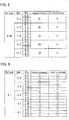
- Figs. 8 to 11 show the results of temperature rise tests and rotation torque tests as described above that were conducted on bearing samples of which the values of the arithmetic mean roughness Ra, the roughness curve skewness Rsk and the roughness curve kurtosis Rku were varied.
- the large flange surface has an arithmetic mean roughness Ra of 0.05, which means that the large flange surface is a particularly smooth finished surface, irrespective of whether or not the roughness curve skewness Rsk of the large flange surface is within the range of -1.0 ⁇ Rsk ⁇ -0.3, and irrespective of whether or not the roughness curve kurtosis Rku of the large flange surface is within the range of 3.0 ⁇ Rsk ⁇ 5.0, the seizure resistance is particularly good, but the stability of torque is particularly low.
- the arithmetic mean roughness Ra of the large flange surface is 0.25, which means that the large flange surface is a particularly coarse surface, irrespective of whether or not the roughness curve skewness Rsk of the large flange surface is within the range of -1.0 ⁇ Rsk ⁇ -0.3, and irrespective of whether or not the roughness curve kurtosis Rku of the large flange surface is within the range of 3.0 ⁇ Rsk ⁇ 5.0, seizure resistance is particularly inferior, whereas the stability of torque is particularly excellent.
- the evaluation results of Figs. 8 to 11 show that, if the arithmetic mean roughness Ra of the large flange surface is 0.1 ⁇ m ⁇ Ra ⁇ 0.2 ⁇ m; the roughness curve skewness Rsk of the large flange surface is -1.0 ⁇ Rsk ⁇ -0.3; and the roughness curve kurtosis Rku of the large flange surface is 3.0 ⁇ Rsk ⁇ 5.0, it is possible to realize both excellent seizure resistance and stable torque.
- Tapered roller bearings that satisfy the conditions of the present invention are suitably used to support shafts of a power transmission device of an automobile such as a differential or a transmission. This is because tapered roller bearings supporting these shafts have to be broken in at a low rotation speed with a preload applied thereto.
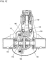
- Fig. 12 exemplifies tapered roller bearings according to the above embodiment as mounted in the power transmission path of an automobile.
- Fig.12 exemplifies a differential constituting the power transmission path of an automobile, and including a drive pinion 104 supported by two tapered roller bearings 102 and 103 so as to be rotatable relative to a housing 101; a ring gear 105 in mesh with the drive pinion 104; a differential gear case 107 to which the ring gear 105 is attached, and which is supported by a pair of tapered roller bearings 106 so as to be rotatable relative to the housing 101; pinions 108 disposed in the differential gear case 107; and a pair of side gears 109 in mesh with the pinions 108.
- These elements of the differential are received in the housing 101, in which gear oil is sealed.
- This gear oil also functions as lubricating oil for the tapered roller bearings 102, 103 and 106.
- the tapered roller bearings 102, 103 and 106 correspond to the above embodiment.
- Fig. 13 exemplifies a transmission constituting the power transmission path of an automobile in which tapered roller bearings according to the above embodiment are mounted.
- the transmission of Fig. 13 is a multistage transmission that changes the gear ratio in a stepwise manner, and includes rolling bearings 203 to 208 comprising tapered roller bearings according to the above embodiment, and rotatably supporting rotary shafts (including an input shaft 201 and an output shaft 202) of the transmission.
- the shown transmission also includes the above-mentioned input shaft 201, to which the rotation of the engine is input or transmitted; the above-mentioned output shaft 202, which extends parallel to the input shaft 201; a plurality of gear trains 209 to 212 through which the rotation of the input shaft 201 is transmitted to the output shaft 202; and clutches (not shown) mounted between the input shaft 201 and the respective gear trains 209 to 212, or between the output shaft 202 and the respective gear trains 209 to 212. By selectively engaging any one of the clutches, the rotation of the input shaft 201 is transmitted through the selected one of the gear trains 209 to 212 to the output shaft 202 in a selected gear ratio.
- the rotation of the output shaft 202 is transmitted to an output gear 213, and the rotation of the output gear 213 is transmitted to e.g., a differential.
- the inputs shaft 201 is rotatably supported by the tapered roller bearings 203 and 204, and the output shaft 202 is rotatably supported by the tapered roller bearings 205 and 206.
- the shown transmission is configured such that lubricating oil splashed due to the rotation of the output gear, or injected from nozzles (not shown) located within a housing 214 of the transmission is splashed onto the sides of the tapered roller bearings 203 to 208.
Landscapes
- Engineering & Computer Science (AREA)
- General Engineering & Computer Science (AREA)
- Mechanical Engineering (AREA)
- Rolling Contact Bearings (AREA)
Abstract
Description
- The present invention relates to a tapered roller bearing.
- In a tapered roller bearing, the roller large end surfaces of the tapered rollers come into sliding contact with the large flange surface of the inner ring. In order to prevent seizure between the roller large end surfaces and the large flange surface due to their metal contact, the surface roughness of the large flange surface is adjusted such that a sufficient oil film is formed between the roller large end surfaces and the large flange surface.
- When a tapered roller bearing is used in an automotive power transmission path, or in a device such as an industrial machine, a preload is applied to the tapered roller bearing for the purpose of improving the rigidity and rotation accuracy of the tapered roller bearing. In this case, it is necessary to determine an appropriate amount of the preload by measuring the rotation torque of the tapered roller bearing. The rotation torque is measured while rotating the tapered roller bearing at a low speed (normally 100 r/min or less), for the convenience of the step of mounting the tapered roller bearing to a device. While the tapered roller bearing is rotating at a low speed, the rotation torque of the tapered roller bearing is generated mainly by the sliding friction between the roller large end surfaces of the tapered rollers and the large flange surface of the inner ring, and is affected only to a very small degree by the rolling friction generated between the tapered rollers and the inner and outer rings. Therefore, in order to accurately measure the rotation torque of the tapered roller bearing, it is necessary to fully break in the tapered roller bearing at a low rotation speed, while applying a preload to the tapered roller bearing until the roller large end surfaces of the tapered rollers come into contact with the large flange surface of the inner ring (i.e., until the width dimension of the bearing is stabilized).
- The below-identified
Patent Document 1 discloses a tapered roller bearing in which the surface roughness Ra of the large flange surface of the inner ring is set within the range of 0.05 to 0.20 µm so as to maintain appropriate lubrication condition between the large flange surface of the inner ring and the roller large end surfaces of the tapered rollers. - That is, if the surface roughness Ra of the large flange surface is less than 0.05 µm, when the tapered roller bearing is broken in, the lubrication condition between the large flange surface of the inner ring and the roller large end surfaces of the tapered rollers becomes mixed lubrication which is a mixed state of fluid lubrication and boundary lubrication. As a result thereof, the friction coefficient fluctuates to a large degree, and thus the measured rotation torque also fluctuates to a large degree, thereby making it difficult to accurately manage the preload. In contrast thereto, if the surface roughness Ra of the large flange surface is 0.05 µm or more, the lubrication condition between the large flange surface and the roller large end surfaces becomes boundary lubrication. As a result thereof, the friction coefficient is stabilized, thereby making it possible to accurately manage the preload. While the bearing is rotating at a normal speed exceeding 100 (r/min), a sufficient oil film is formed between the large flange surface and the roller large end surfaces, so that the lubrication condition between the large flange surface and the roller large end surfaces becomes fluid lubrication, and thus the friction coefficient is small. If the surface roughness Ra of the large flange surface is more than 0.20 µm, when the temperature of the bearing rises in the high-speed rotation range, and the viscosity of lubricating oil decreases, an oil film having a sufficient thickness is not formed between the large flange surface and the roller large end surfaces. This may generate seizure between the roller large end surfaces and the large flange surface.
- The below-identified Patent Document 2 discloses a tapered roller bearing in which the surface roughness Ra of each of the roller large end surfaces of the tapered rollers is set to be 0.1 µm or less, and the surface roughness Ra of the large flange surface of the inner ring is set to be 0.2 µm or less, thereby improving the stability of rotation torque when the bearing is broken in.
-
- Patent document 1: Japanese Unexamined Patent Application Publication No.
2000-170774 - Patent document 2: Japanese Unexamined Patent Application Publication No.
2002-139055 - While, in each of the tapered roller bearings of
Patent Documents 1 and 2, the surface roughness Ra of the large flange surface of the inner ring is set within the above predetermined range so as to stabilize rotation torque while the bearing is rotating at a low speed with a preload applied to the bearing, the above predetermined range covers the roughness level of superfinishing (e.g., Ra = 0.08 µm or less), which may destabilize rotation torque. - On the other hand, it is considered that, if the surface roughness Ra of the large flange surface of the inner ring is larger than the roughness level of superfinishing, it is possible to stabilize rotation torque while the bearing is rotating at a low speed. However, the seizure resistance in this case is inferior compared to when the surface roughness Ra of the large flange surface covers the roughness level of superfinishing.
- Thus, simply by setting the surface roughness Ra of the large flange surface, it is difficult to realize both stable rotation torque while the bearing is rotating at a low speed, and excellent seizure resistance between the large flange surface and the roller large end surfaces.
- In view of the above background, it is an object of the present invention to provide a tapered roller bearing capable of realizing both stable rotation torque while the bearing is rotating at a low speed, and excellent seizure resistance between the large flange surface and the roller large end surfaces.
- In order to achieve the above object, the present invention provides a tapered roller bearing comprising: tapered rollers each having a roller large end surface; and an inner ring having a large flange surface configured to come into sliding contact with the roller large end surfaces of the tapered rollers, characterized in that the large flange surface has: an arithmetic mean roughness Ra of 0.1 µm ≤ Ra ≤ 0.2 µm; a roughness curve skewness Rsk of -1.0 ≤ Rsk ≤ -0.3; and a roughness curve kurtosis Rku of 3.0 ≤ Rku ≤ 5.0.
- The arithmetic mean roughness Ra, the roughness curve skewness Rsk, and the roughness curve kurtosis Rku according to the present invention are stipulated in B0601:2013 of the Japanese Industrial Standards (JIS).
- In the present invention, since the arithmetic mean roughness Ra of the large flange surface of the inner ring is within the range of 0.1 to 0.2 µm, the large flange surface is suitable for stabilizing rotation torque while the tapered roller bearing is rotating at a low speed, i.e., within the range of 0 to 200 (r/min). However, the large flange surface of which only the arithmetic mean roughness Ra is adjusted in this manner will be inferior in seizure resistance to a surface having a roughness of the super-finished level. Therefore, according to the present invention, the roughness curve skewness Rsk and the roughness curve kurtosis Rku of the large flange surface are also adjusted in the following manner.
- Specifically, if the roughness curve skewness Rsk is Rsk < 0, i.e., within a negative numerical value range, this means that a larger portion of the roughness curve is located above the average line, which in turn means that a greater area of the large flange surface forms a flat surface, so that an oil film can be formed in a reliable manner. Thus, the roughness curve skewness Rsk of the large-diameter flange surface is set within the range of -1.0 to -0.3. On the other hand, if the roughness curve kurtosis Rku is less than 3.0, the distribution curve of protrusions and recesses distributed on the large flange surface has a flattened shape. However, in order to stabilize rotation torque, higher protrusions on the large flange surface need to be maintained to some extent. Thus, the roughness curve kurtosis Rku is set within the range of 3.0 to 5.0.
- By adjusting the Ra, Rsk and Rku values within the above respective ranges, it is possible to realize both stable rotation torque while the bearing is rotating at a low speed, and excellent seizure resistance between the large flange surface and the roller large end surfaces.
- For example, the roller large end surface of each of the tapered rollers has an arithmetic mean roughness Ra of 0.1 µm or less. Since bearing functions are less affected by the surface roughnesses of the roller large end surfaces than by the surface roughness of the large flange surface of the inner ring, the surface roughness of each of the roller large end surfaces may be managed based solely on the arithmetic mean roughness Ra, and not based on the skewness Rsk and kurtosis Rku.
- For example, the large flange surface has one of: a shape generated by a straight generatrix; a shape generated by a concave generatrix having a maximum depth of 1 µm or less at a mid-portion thereof; and a shape generated by a convex generatrix having a maximum height of 1 µm or less at a mid-portion thereof. The contact between the roller large end surfaces and the large flange surface is ideally the contact between spherical surfaces and a flat surface, because this can realize particularly excellent seizure resistance between the roller large end surfaces and the large flange surface. Therefore, the large flange surface is preferably generated by a substantially straight generatrix within the industrially feasible range. If the large flange surface is generated by a concave generatrix recessed toward its center, or by a convex generatrix bulging toward its center, its maximum height or depth has to be limited to 1 µm, because otherwise, it is impossible to ensure an excellent wedge effect of lubricating oil.
- The tapered roller bearing according to the present invention is suitable for use in power transmission devices of an automobile, such as a differential and a transmission, which constitute the power transmission path through which motive power is transmitted from the driving source of the automobile to wheels.
- Since the tapered roller bearing of the present invention has a structure as described above, it is possible to realize both stable rotation torque while the bearing is rotating at a low speed, and excellent seizure resistance between the large flange surface and the roller large end surfaces.
-
-
Fig. 1 is a partial sectional view of a tapered roller bearing embodying the present invention. -
Fig. 2 is an enlarged view illustrating the large flange surface ofFig. 1 , and its vicinity. -
Fig. 3 is a partial sectional view illustrating the large flange surface ofFig. 1 generated by a different generatrix. -
Fig. 4 is a partial sectional view illustrating the large flange surface ofFig. 1 generated by a still different generatrix. -
Fig. 5 is a conceptual diagram exemplifying how the large flange surface is affected by respective ranges of the roughness curve skewness Rsk of the large flange surface. -
Fig. 6 is a conceptual diagram exemplifying how the large flange surface is affected by respective ranges of the roughness curve kurtosis Rku of the large flange surface. -
Fig. 7 is a graph showing the relationship between rotation torque and rotation speed in an Example and Comparative Examples. -
Fig. 8 is a view showing the result of an evaluation test conducted according to the above Example so as to evaluate seizure resistance and the stability of rotation torque, while using various numerical values relative to surface properties of the large flange surface. -
Fig. 9 is a view showing the result of an evaluation test conducted according to the above Example so as to evaluate seizure resistance and the stability of rotation torque, while using various numerical values partially different from those ofFig. 8 , relative to surface properties of the large flange surface. -
Fig. 10 is a view showing the result of an evaluation test conducted according to the above Example so as to evaluate seizure resistance and the stability of rotation torque, while using various numerical values partially different from those ofFigs. 8 and 9 , relative to surface properties of the large flange surface. -
Fig. 11 is a view showing the result of an evaluation test conducted according to the above Example so as to evaluate seizure resistance and the stability of rotation torque, while using various numerical values partially different from those ofFigs. 8 to 10 , relative to surface properties of the large flange surface. -
Fig. 12 is a sectional view of an automotive differential in which tapered roller bearings according to the present invention are mounted. -
Fig. 13 is a sectional view of an automotive transmission in which tapered roller bearings according to the present invention are mounted. - A tapered roller bearing 1 embodying the present invention is now described with reference to
Figs. 1 and2 of the attached drawings. - As illustrated in
Fig. 1 , the taperedroller bearing 1 includes aninner ring 10, anouter ring 20, a plurality of taperedrollers 30, and acage 40 retaining the taperedrollers 30. - The
inner ring 10, theouter ring 20 and the taperedrollers 30 are made of steel. - The
inner ring 10 and theouter ring 20 are annular bearing parts arranged coaxially with each other. Theinner ring 10 has araceway 11 on its outer periphery, and alarge flange surface 12. Theouter ring 20 has araceway 21 on its inner periphery. Theraceways - Each tapered
roller 30 has a conical rollingsurface 31, a rollersmall end surface 32, and a rollerlarge end surface 33. The rollingsurface 31 is disposed between theraceway 11 of theinner ring 10 and theraceway 21 of theouter ring 20. The rollersmall end surface 32 is the side surface of the taperedroller 30 at its small-diameter end. The rollerlarge end surface 33 is the side surface of the taperedroller 30 at its large-diameter end. - The roller
large end surface 33 is a spherical surface. - The surface roughnesses of the roller large end surfaces 33 of the tapered
rollers 30 have a lesser influence on the seizure resistance and other bearing functions than the surface roughness of thelarge flange surface 12 of theinner ring 10. Therefore, the surface roughness of the rollerlarge end surface 33 of each taperedroller 30 may be managed simply based on the arithmetic mean roughness Ra. Specifically, the arithmetic mean roughness Ra of the rollerlarge end surface 33 is set to be 0.1 µm or less. The term "arithmetic mean roughness Ra", as used herein, refers to the arithmetic mean roughness Ra stipulated in 4.2.1 of B0601:2013 of the Japanese Industrial Standards (JIS). The unit of the arithmetic mean roughness Ra is µm. - As illustrated in
Fig. 2 , thelarge flange surface 12 of theinner ring 10 comes into sliding contact with the roller large end surfaces 33 of the taperedrollers 30. That is, thelarge flange surface 12 of theinner ring 10 is a portion of the surface of the inner ring that can come into sliding contact with the roller large end surfaces 33 of the taperedrollers 30 while the bearing is rotating. Thelarge flange surface 12 has a shape generated by a straight generatrix (i.e., a conical shape). - Otherwise, the
large flange surface 12 may have a shape generated by a concave generatrix having a maximum depth Δ1 of 1 µm or less at its mid-portion, as illustrated inFig. 3 , or a shape generated by a convex generatrix having a maximum height Δ1 of 1 µm or less at its mid-portion, as illustrated inFig. 4 . In particular, the concave generatrix is gradually recessed in the direction away from the rollerlarge end surface 33, from both ends p1 and p2 of the concave generatrix toward the center of the straight reference line (see the dashed line inFig. 3 ) connecting both ends p1 and p2 of the concave generatrix defining thelarge flange surface 12. The convex generatrix gradually bulges toward the rollerlarge end surface 33, from both ends p1 and p2 of the convex generatrix toward the center of the imaginary straight reference line (see the dashed line inFig. 4 ) connecting both ends p1 and p2 of the convex generatrix. - By using a
large flange surface 12 having one of a shape generated by a straight generatrix (seeFig. 2 ); a shape generated by a concave generatrix having a maximum depth of 1 µm or less at its mid-portion (seeFig. 3 ); and a shape generated by a convex generatrix having a maximum height of 1 µm or less at its mid-portion (seeFig. 4 ), the contact between the roller large end surfaces 33 and thelarge flange surface 12 will be the contact between spherical surfaces and a flat surface, or a contact very similar to this. This ensures an excellent wedge effect of lubricating oil between the' roller large end surfaces 33 and thelarge flange surface 12. - The
large flange surface 12 has an arithmetic mean roughness Ra of 0.1 µm ≤ Ra ≤ 0.2 µm. By setting the arithmetic mean roughness Ra of thelarge flange surface 12 within the range of 0.1 to 0.2 µm, thelarge flange surface 12 is capable of stabilizing rotation torque while the taperedroller bearing 1, shown inFig. 1 , is rotating at a low speed, i.e., within the range of 0 to 200 (r/min). - The
large flange surface 12 has a roughness curve skewness Rsk of -1.0 ≤ Rsk ≤ -0.3. The term "roughness curve skewness Rsk", as used herein, refers to the roughness curve skewness Rsk stipulated in 4.2.3 of B0601:2013 of the Japanese Industrial Standards (JIS), and defined by the followingformula 1.
[Formula 1]
- As shown in
formula 1, the roughness curve skewness Rsk is the mean of the cubes of Z(x) values within a reference length of a surface to be evaluated, made dimensionless by the cube of the root mean square roughness Rq of the profile curve. The roughness curve skewness Rsk is a numerical value indicative of the degree of asymmetry of the probability density function of the contour curve, and is a parameter strongly affected by protruding peaks and valleys of the profile curve.Fig. 5 exemplifies a roughness curve satisfying the relation skewness Rsk > 0, and a roughness curve satisfying the relation skewness Rsk < 0. As is apparent from the comparison of these roughness curves, in the case of skewness Rsk < 0, the number of protruding peaks is relatively small, so that an oil film is less likely to break on the surface, and thus seizure is less likely to occur. However, the larger the negative value of the skewness Rsk is, the wider the valleys of the roughness curve tends to be, and thus the larger the distances between the adjacent protruding peaks (which means that in the case of the large flange surface of the inner ring of a tapered roller bearing, the distances between portions of the large flange surface that come into contact with the roller large end surfaces are large). If the valleys are too wide, stress concentration will occur at the boundaries between the respective protruding peaks and the adjacent valleys, thereby making it difficult to form an oil film on the surface. By setting the roughness curve skewness Rsk of thelarge flange surface 12, illustrated inFig. 2 , within the range of -0.1 to -0.3, thelarge flange surface 12 is practically a flat surface, so that an oil film can be formed reliably thereon. - The
large flange surface 12 has a roughness curve kurtosis Rku of 3.0 ≤ Rku ≤ 5.0. The term "roughness curve kurtosis Rku", as used herein, refers to the roughness curve kurtosis Rku stipulated in 4.2.4 of B0601:2013 of the Japanese Industrial Standards (JIS), and defined by the following formula 2.
[Formula 2]
- As shown in formula 2, the roughness curve kurtosis Rku is the mean of the fourth powers of Z(x) values within a reference length of a surface to be evaluated, made dimensionless by the fourth power of the root mean square roughness Rq of the profile curve. The roughness curve kurtosis Rku is a numerical value indicative of the degree of peakedness (steepness) of the probability density function of the contour curve, and is a parameter strongly affected by protruding peaks and valleys of the profile curve.
Fig. 6 exemplifies a roughness curve satisfying the relation kurtosis Rku > 3, and a roughness curve satisfying the relation kurtosis Rku < 3. As is apparent from the comparison of these roughness curves, in the case of kurtosis Rku > 3, the peaks tend to be relatively pointed, so that moderate metal contact occurs, thereby stabilizing torque. However, if the positive value of the kurtosis Rku is too large, excessive metal contact tends to occur, so that seizure resistance tends to deteriorate. Thus, by setting the roughness curve kurtosis Rku of thelarge flange surface 12, illustrated inFig. 2 , within the range of 3.0 to 5.0, the roughness of thelarge flange surface 12, which is determined by the protrusions thereof, will be such that thelarge flange surface 12 is capable of stabilizing rotation torque while the bearing is rotating at a low speed. - The arithmetic mean roughness Ra, the roughness curve skewness Rsk, and the roughness curve kurtosis Rku can be all measured by a surface roughness measuring device.
- Since the roughness of the
large flange surface 12 of the taperedroller bearing 1 according to the present invention is determined such that the arithmetic mean roughness Ra is within the range of 0.1 to 0.2 µm; the roughness curve skewness Rsk is within the range of -0.1 to -0.3; and the roughness curve kurtosis Rku is within the range of 3.0 to 5.0, it is possible to stabilize rotation torque while the bearing is rotating at a low speed, and also improve seizure resistance between thelarge flange surface 12 and the roller large end surfaces 33. - If the arithmetic mean roughness Ra of the
large flange surface 12 is within the range of 0.1 to 0.2 µm, but the roughness curve skewness Rsk and roughness curve kurtosis Rku of thelarge flange surface 12 are out of the above respective ranges, rotation torque while the bearing is rotating at a low speed may stabilize, but the seizure resistance in this case will be inferior compared to when the arithmetic mean roughness Ra is less than 0.1 µm. - A surface roughness that satisfies all of the above three roughness conditions is so fine that, if attempts are made to form the
large flange surface 12 by grinding, the grinding resistance is too large, so that grinding burn may occur. Specifically, since a grinder for grinding has a coarser abrasive surface than a grinder for superfinishing, if attempts are made to form a surface having a roughness level equivalent to a surface roughness Ra of 0.1 to 0.2 µm by grinding, the grinding resistance will be too large. Since, for this reason, it is difficult to finish thelarge flange surface 12 by grinding, thelarge flange surface 12 is preferably super-finished to satisfy the above three roughness conditions. For example, by super-finishing thelarge flange surface 12 in an extremely short time (0.5 seconds to 2 seconds), it is possible to satisfy the above three roughness conditions. - (First and second) Examples (of the invention) (first and second) Comparative Examples 1, and (first and second) Comparative Examples 2, which are all tapered roller bearings model No. 30307D, were prepared and subjected to rotation torque tests and temperature rise tests.
- The Examples, which correspond to the above embodiment, had a large flange surface having an arithmetic mean roughness Ra of 0.149 µm; a roughness curve skewness Rsk of -0.96; and a roughness curve kurtosis Rku of 4.005.
- Comparative Examples 1 had a large flange surface having an arithmetic mean roughness Ra of 0.2 µm.
- Comparative Examples 2 had a large flange surface having an arithmetic mean roughness Ra of 0.08 µm, which is a roughness level of superfinishing.
- The large flange surface of each of Comparative Examples 1 had a roughness curve skewness Rsk of -1.053, and a roughness curve kurtosis Rku of 2.563. The large flange surface of each of Comparative Example 2 had a roughness curve skewness Rsk of -1.298, and a roughness curve kurtosis Rku of 5.103.
- The arithmetic mean roughnesses Ra of the roller large end surfaces of the Examples, and Comparative Examples 1 and 2 were 0.1 µm or less and substantially equal to each other.
- The first Example, and first Comparative Examples 1 and 2 were subjected to the rotation torque tests under the following common conditions: the number of revolutions of the bearing per minute (r/min) was set within the range of 0 to 200; and antirust oil having a kinematic viscosity of 16.5 mm2/s at 40 degrees Celsius, and 3.5 mm2/s at 100 degrees Celsius was applied to the bearing to lubricate the bearing.
-
Fig. 7 shows the measurement results of the rotation torque tests for the Example and Comparative Examples 1 and 2. As is apparent from the comparison of the measurement results inFig. 7 , the Example showed stable torque characteristics substantially equivalent to those of Comparative Example 1, in which the arithmetic mean roughness Ra of the large flange surface is 0.2 µm. The reason why the Example showed such stable torque is apparently because, in the low-speed rotation range of the Example, the wedge effect of the lubricating oil between the large flange surface and the roller large end surfaces is small, so that the oil film therebetween is thin, and as a result, (not mixed lubrication but) boundary lubrication state is present therebetween in the range of 0 to 200 r/min. - On the other hand, in Comparative Example 2, in which the arithmetic mean roughness Ra of the large flange surface is 0.08 µm, the torque value sharply decreases up to 50 r/min. This is apparently because the roughness of the large flange surface of Comparative Example 2 is small, so that an oil film having a sufficient thickness is formed up to 50 r/min, and in the rotation range higher than 50 r/min, the torque value is more strongly affected by the rolling resistance of the rolling surfaces of the tapered rollers. In an actual production line, the preload management (torque check) after assembling tapered roller bearings is performed, in many cases, within the range of 10 to 50 r/min. This means that the Example, which shows stable torque in this rotation range, can be assembled more easily because the preload management is easier.
- The second Example, and the second Comparative Examples 1 and 2, which were prepared in the same production lot as the first Example and first Comparative Examples 1 and 2, were subjected to the temperature rise tests under the following common conditions: a radial load of 17 kN and an axial load of 1.5 kN were applied to the bearings; and the bearings were immersed, for lubrication, in turbine oil VG56 to the center axes thereof. In each of the temperature rise tests, the temperature of the outer ring was measured at predetermined numbers of revolutions of the bearing. Table 1 shows the results of the temperature measurement, in which the symbol "O" indicates that the temperature was 120 degrees Celsius or less; the symbol "Δ" indicates that the temperature was more than 120 degrees Celsius and less than 150 degrees Celsius; and the symbol "X" indicates that the temperature was 150 degrees Celsius or more.
[Table 1] 500 r/min 1000 r/min 2000 r/min 3000 r/min 4000 r/min 5000 r/min Comparative Example 1 ○ ○ Δ × - - Comparative Example 2 ○ ○ ○ ○ ○ ○ Example ○ ○ ○ ○ ○ Δ - As is apparent from Table 1, the Example showed seizure resistance similar to the seizure resistance in Comparative Example 2, in which the arithmetic mean roughness Ra of the large flange surface is 0.08 pm.
-
Figs. 8 to 11 show the results of temperature rise tests and rotation torque tests as described above that were conducted on bearing samples of which the values of the arithmetic mean roughness Ra, the roughness curve skewness Rsk and the roughness curve kurtosis Rku were varied. - As shown in
Fig. 8 , if the large flange surface has an arithmetic mean roughness Ra of 0.05, which means that the large flange surface is a particularly smooth finished surface, irrespective of whether or not the roughness curve skewness Rsk of the large flange surface is within the range of -1.0 ≤ Rsk ≤ -0.3, and irrespective of whether or not the roughness curve kurtosis Rku of the large flange surface is within the range of 3.0 ≤ Rsk ≤ 5.0, the seizure resistance is particularly good, but the stability of torque is particularly low. - As shown in
Figs. 9 and10 , if the large flange surface has an arithmetic mean roughness Ra of 0.1 or 0.2, the seizure resistance tends to be worse than when Ra = 0.05, whereas the stability of torque tends to be better than when Ra = 0.05.Figs. 9 and10 also indicate that if Ra = 0.1 or 0.2, and if the roughness curve skewness Rsk of the large flange surface is Rsk < -1.0, a sufficient oil film is less likely to be formed, thus adversely affecting seizure resistance, and that if Ra = 0.1 or 0.2 and if Rsk > -0.3, it is impossible to realize both excellent seizure resistance and stable torque irrespective of the value of the roughness curve kurtosis Rku of the large flange surface.Figs. 9 and10 further indicate that if Ra = 0.1 or 0.2, and if the roughness curve kurtosis Rku of the large flange surface is Rku < 3, the stability of torque deteriorates, due to the oil film growing too thick. On the other hand, if Rku > 5, minute peaks on the large flange surface tend to be so pointed as to cause the large flange surface to come into metal contact with the roller large end surfaces. As a result thereof, a sufficient oil film is less likely to be formed, thus adversely affecting the seizure resistance. - As shown in
Fig. 11 , if the arithmetic mean roughness Ra of the large flange surface is 0.25, which means that the large flange surface is a particularly coarse surface, irrespective of whether or not the roughness curve skewness Rsk of the large flange surface is within the range of -1.0 ≤ Rsk ≤ -0.3, and irrespective of whether or not the roughness curve kurtosis Rku of the large flange surface is within the range of 3.0 ≤ Rsk ≤ 5.0, seizure resistance is particularly inferior, whereas the stability of torque is particularly excellent. - As a whole, the evaluation results of
Figs. 8 to 11 show that, if the arithmetic mean roughness Ra of the large flange surface is 0.1 µm ≤ Ra ≤ 0.2 µm; the roughness curve skewness Rsk of the large flange surface is -1.0 ≤ Rsk ≤ -0.3; and the roughness curve kurtosis Rku of the large flange surface is 3.0 ≤ Rsk ≤ 5.0, it is possible to realize both excellent seizure resistance and stable torque. - Tapered roller bearings that satisfy the conditions of the present invention are suitably used to support shafts of a power transmission device of an automobile such as a differential or a transmission. This is because tapered roller bearings supporting these shafts have to be broken in at a low rotation speed with a preload applied thereto.
Fig. 12 exemplifies tapered roller bearings according to the above embodiment as mounted in the power transmission path of an automobile. - More specifically,
Fig.12 exemplifies a differential constituting the power transmission path of an automobile, and including adrive pinion 104 supported by two taperedroller bearings housing 101; aring gear 105 in mesh with thedrive pinion 104; adifferential gear case 107 to which thering gear 105 is attached, and which is supported by a pair of taperedroller bearings 106 so as to be rotatable relative to thehousing 101;pinions 108 disposed in thedifferential gear case 107; and a pair of side gears 109 in mesh with thepinions 108. These elements of the differential are received in thehousing 101, in which gear oil is sealed. This gear oil also functions as lubricating oil for the taperedroller bearings roller bearings -
Fig. 13 exemplifies a transmission constituting the power transmission path of an automobile in which tapered roller bearings according to the above embodiment are mounted. - The transmission of
Fig. 13 is a multistage transmission that changes the gear ratio in a stepwise manner, and includes rollingbearings 203 to 208 comprising tapered roller bearings according to the above embodiment, and rotatably supporting rotary shafts (including aninput shaft 201 and an output shaft 202) of the transmission. The shown transmission also includes the above-mentionedinput shaft 201, to which the rotation of the engine is input or transmitted; the above-mentionedoutput shaft 202, which extends parallel to theinput shaft 201; a plurality ofgear trains 209 to 212 through which the rotation of theinput shaft 201 is transmitted to theoutput shaft 202; and clutches (not shown) mounted between theinput shaft 201 and therespective gear trains 209 to 212, or between theoutput shaft 202 and therespective gear trains 209 to 212. By selectively engaging any one of the clutches, the rotation of theinput shaft 201 is transmitted through the selected one of thegear trains 209 to 212 to theoutput shaft 202 in a selected gear ratio. The rotation of theoutput shaft 202 is transmitted to anoutput gear 213, and the rotation of theoutput gear 213 is transmitted to e.g., a differential. Theinputs shaft 201 is rotatably supported by the taperedroller bearings output shaft 202 is rotatably supported by the taperedroller bearings housing 214 of the transmission is splashed onto the sides of the taperedroller bearings 203 to 208. - The above embodiment and Examples are merely exemplified in every respect, and the present invention is not limited to the above embodiment and Examples. The scope of the present invention is indicated by the claims, and should be understood to include all modifications within the scope and the meaning equivalent to the scope of the claims.
-
- 1, 102, 103, 106, 203 to 208: tapered roller bearing
- 10: inner ring
- 12: large flange surface
- 30: tapered roller
- 33: roller large end surface
Claims (4)
- A tapered roller bearing comprising:tapered rollers each having a roller large end surface; andan inner ring having a large flange surface configured to come into sliding contact with the roller large end surfaces of the tapered rollers,characterized in that the large flange surface has:an arithmetic mean roughness Ra of 0.1 µm ≤ Ra ≤ 0.2 µm;a roughness curve skewness Rsk of -1.0 ≤ Rsk ≤ -0.3; anda roughness curve kurtosis Rku of 3.0 ≤ Rku ≤ 5.0.
- The tapered roller bearing according to claim 1, wherein the roller large end surface of each of the tapered rollers has an arithmetic mean roughness Ra of 0.1 µm or less.
- The tapered roller bearing according to claim 1 or 2, wherein the large flange surface has one of:a shape generated by a straight generatrix;a shape generated by a concave generatrix having a maximum depth of 1 µm or less at a mid-portion thereof; anda shape generated by a convex generatrix having a maximum height of 1 µm or less at a mid-portion thereof.
- The tapered roller bearing according to any one of claims 1 to 3, mounted in a power transmission device of an automobile.
Applications Claiming Priority (2)
| Application Number | Priority Date | Filing Date | Title |
|---|---|---|---|
| JP2017029745A JP6934728B2 (en) | 2017-02-21 | 2017-02-21 | Tapered roller bearing |
| PCT/JP2018/005397 WO2018155320A1 (en) | 2017-02-21 | 2018-02-16 | Conical roller bearing |
Publications (3)
| Publication Number | Publication Date |
|---|---|
| EP3587847A1 true EP3587847A1 (en) | 2020-01-01 |
| EP3587847A4 EP3587847A4 (en) | 2020-02-12 |
| EP3587847B1 EP3587847B1 (en) | 2021-11-10 |
Family
ID=63253807
Family Applications (1)
| Application Number | Title | Priority Date | Filing Date |
|---|---|---|---|
| EP18757785.3A Not-in-force EP3587847B1 (en) | 2017-02-21 | 2018-02-16 | Conical roller bearing |
Country Status (5)
| Country | Link |
|---|---|
| US (1) | US10968947B2 (en) |
| EP (1) | EP3587847B1 (en) |
| JP (1) | JP6934728B2 (en) |
| CN (1) | CN110312875A (en) |
| WO (1) | WO2018155320A1 (en) |
Families Citing this family (4)
| Publication number | Priority date | Publication date | Assignee | Title |
|---|---|---|---|---|
| DE102017113701A1 (en) * | 2017-06-21 | 2018-12-27 | Schaeffler Technologies AG & Co. KG | Noise- and wear-optimized rolling bearing for supporting a shaft |
| EP3815226B1 (en) * | 2018-06-11 | 2023-05-31 | iFIT Inc. | Increased durability linear actuator |
| IT201900000238A1 (en) * | 2019-01-09 | 2020-07-09 | Skf Ab | ROLLING CONTACT BEARING WITH IMPROVED PERFORMANCES |
| CN111188832A (en) * | 2020-03-12 | 2020-05-22 | 洛阳Lyc轴承有限公司 | Energy efficiency type tapered roller bearing |
Family Cites Families (13)
| Publication number | Priority date | Publication date | Assignee | Title |
|---|---|---|---|---|
| JP2000170774A (en) | 1998-12-01 | 2000-06-20 | Ntn Corp | Conical roller bearing and gear shaft support device for vehicle |
| US6328477B1 (en) | 1998-11-27 | 2001-12-11 | Ntn Corporation | Tapered roller bearings and gear shaft support devices |
| JP2002139055A (en) * | 2000-08-25 | 2002-05-17 | Ntn Corp | Tapered roller bearing and its preload setting method |
| JP4029574B2 (en) * | 2001-01-26 | 2008-01-09 | 株式会社ジェイテクト | Tapered roller bearings |
| DE60217941T2 (en) * | 2001-05-16 | 2007-10-18 | Jtekt Corp., Osaka | Rolling bearings with line-shaped grinding marks on the roller end surfaces and on the flange surface |
| JP2004324670A (en) * | 2003-04-21 | 2004-11-18 | Fuji Heavy Ind Ltd | Roller bearing |
| JP2011196543A (en) * | 2010-02-23 | 2011-10-06 | Nsk Ltd | Roller bearing and process of producing the same |
| US20130170780A1 (en) * | 2010-02-23 | 2013-07-04 | Nsk Ltd. | Roller Bearing and Method for Manufacturing the Same |
| CN102639890A (en) * | 2010-11-12 | 2012-08-15 | 日本精工株式会社 | Actuator and method for producing same |
| JP2012241805A (en) * | 2011-05-19 | 2012-12-10 | Nsk Ltd | Tapered roller bearing and method of manufacturing the same |
| JP5927960B2 (en) * | 2011-05-30 | 2016-06-01 | 日本精工株式会社 | Roller bearing |
| JP5831131B2 (en) | 2011-10-24 | 2015-12-09 | 日本精工株式会社 | Roller bearing and manufacturing method thereof |
| JP6492646B2 (en) * | 2014-12-26 | 2019-04-03 | 株式会社ジェイテクト | Tapered roller bearing |
-
2017
- 2017-02-21 JP JP2017029745A patent/JP6934728B2/en not_active Expired - Fee Related
-
2018
- 2018-02-16 CN CN201880012353.XA patent/CN110312875A/en active Pending
- 2018-02-16 WO PCT/JP2018/005397 patent/WO2018155320A1/en not_active Ceased
- 2018-02-16 US US16/486,886 patent/US10968947B2/en not_active Expired - Fee Related
- 2018-02-16 EP EP18757785.3A patent/EP3587847B1/en not_active Not-in-force
Also Published As
| Publication number | Publication date |
|---|---|
| EP3587847A4 (en) | 2020-02-12 |
| US20200011375A1 (en) | 2020-01-09 |
| JP6934728B2 (en) | 2021-09-15 |
| US10968947B2 (en) | 2021-04-06 |
| CN110312875A (en) | 2019-10-08 |
| JP2018135921A (en) | 2018-08-30 |
| EP3587847B1 (en) | 2021-11-10 |
| WO2018155320A1 (en) | 2018-08-30 |
Similar Documents
| Publication | Publication Date | Title |
|---|---|---|
| EP3587847B1 (en) | Conical roller bearing | |
| US6328477B1 (en) | Tapered roller bearings and gear shaft support devices | |
| CN111919040A (en) | Tapered roller bearing | |
| EP2503168A1 (en) | Rotation support device for pinion shaft | |
| CN110325748A (en) | Tapered roller bearing | |
| US10890213B2 (en) | Tapered roller bearing | |
| KR102647465B1 (en) | conical roller bearings | |
| JP7504270B2 (en) | Tapered roller bearings | |
| US7540665B2 (en) | Tapered roller bearing | |
| JP2019066040A (en) | Taper roller bearing | |
| EP1754899A2 (en) | Tapered roller bearing and bearing apparatus of a transmission | |
| JPWO2008050378A1 (en) | Gear and gear drive device | |
| JP6965007B2 (en) | Conical roller bearing | |
| EP1754903B1 (en) | Self-aligining roller bearing | |
| CN112513479B (en) | Tapered roller bearing | |
| CN105715671B (en) | Biserial spherical roller bearing | |
| JP7032272B2 (en) | Conical roller bearing | |
| JP6858051B2 (en) | Tapered roller bearing | |
| JP5312791B2 (en) | Gear and gear drive device | |
| JP7273210B2 (en) | tapered roller bearing | |
| JP7405544B2 (en) | tapered roller bearing | |
| EP1770293B1 (en) | Roller bearing for automobile | |
| JP2006316821A (en) | Rolling bearing for planetary gear mechanism | |
| JP2007127261A (en) | Gear and gear drive unit | |
| JP2007127260A (en) | Gear and gear drive unit |
Legal Events
| Date | Code | Title | Description |
|---|---|---|---|
| STAA | Information on the status of an ep patent application or granted ep patent |
Free format text: STATUS: THE INTERNATIONAL PUBLICATION HAS BEEN MADE |
|
| PUAI | Public reference made under article 153(3) epc to a published international application that has entered the european phase |
Free format text: ORIGINAL CODE: 0009012 |
|
| STAA | Information on the status of an ep patent application or granted ep patent |
Free format text: STATUS: REQUEST FOR EXAMINATION WAS MADE |
|
| 17P | Request for examination filed |
Effective date: 20190913 |
|
| AK | Designated contracting states |
Kind code of ref document: A1 Designated state(s): AL AT BE BG CH CY CZ DE DK EE ES FI FR GB GR HR HU IE IS IT LI LT LU LV MC MK MT NL NO PL PT RO RS SE SI SK SM TR |
|
| AX | Request for extension of the european patent |
Extension state: BA ME |
|
| A4 | Supplementary search report drawn up and despatched |
Effective date: 20200115 |
|
| RIC1 | Information provided on ipc code assigned before grant |
Ipc: F16C 33/36 20060101ALI20200109BHEP Ipc: F16C 19/36 20060101ALI20200109BHEP Ipc: F16C 33/58 20060101AFI20200109BHEP |
|
| DAV | Request for validation of the european patent (deleted) | ||
| DAX | Request for extension of the european patent (deleted) | ||
| STAA | Information on the status of an ep patent application or granted ep patent |
Free format text: STATUS: EXAMINATION IS IN PROGRESS |
|
| 17Q | First examination report despatched |
Effective date: 20201112 |
|
| GRAP | Despatch of communication of intention to grant a patent |
Free format text: ORIGINAL CODE: EPIDOSNIGR1 |
|
| STAA | Information on the status of an ep patent application or granted ep patent |
Free format text: STATUS: GRANT OF PATENT IS INTENDED |
|
| INTG | Intention to grant announced |
Effective date: 20210708 |
|
| GRAS | Grant fee paid |
Free format text: ORIGINAL CODE: EPIDOSNIGR3 |
|
| GRAA | (expected) grant |
Free format text: ORIGINAL CODE: 0009210 |
|
| STAA | Information on the status of an ep patent application or granted ep patent |
Free format text: STATUS: THE PATENT HAS BEEN GRANTED |
|
| AK | Designated contracting states |
Kind code of ref document: B1 Designated state(s): AL AT BE BG CH CY CZ DE DK EE ES FI FR GB GR HR HU IE IS IT LI LT LU LV MC MK MT NL NO PL PT RO RS SE SI SK SM TR |
|
| REG | Reference to a national code |
Ref country code: GB Ref legal event code: FG4D |
|
| REG | Reference to a national code |
Ref country code: AT Ref legal event code: REF Ref document number: 1446363 Country of ref document: AT Kind code of ref document: T Effective date: 20211115 Ref country code: CH Ref legal event code: EP |
|
| REG | Reference to a national code |
Ref country code: DE Ref legal event code: R096 Ref document number: 602018026505 Country of ref document: DE |
|
| REG | Reference to a national code |
Ref country code: IE Ref legal event code: FG4D |
|
| REG | Reference to a national code |
Ref country code: LT Ref legal event code: MG9D |
|
| REG | Reference to a national code |
Ref country code: NL Ref legal event code: MP Effective date: 20211110 |
|
| REG | Reference to a national code |
Ref country code: AT Ref legal event code: MK05 Ref document number: 1446363 Country of ref document: AT Kind code of ref document: T Effective date: 20211110 |
|
| PG25 | Lapsed in a contracting state [announced via postgrant information from national office to epo] |
Ref country code: RS Free format text: LAPSE BECAUSE OF FAILURE TO SUBMIT A TRANSLATION OF THE DESCRIPTION OR TO PAY THE FEE WITHIN THE PRESCRIBED TIME-LIMIT Effective date: 20211110 Ref country code: LT Free format text: LAPSE BECAUSE OF FAILURE TO SUBMIT A TRANSLATION OF THE DESCRIPTION OR TO PAY THE FEE WITHIN THE PRESCRIBED TIME-LIMIT Effective date: 20211110 Ref country code: FI Free format text: LAPSE BECAUSE OF FAILURE TO SUBMIT A TRANSLATION OF THE DESCRIPTION OR TO PAY THE FEE WITHIN THE PRESCRIBED TIME-LIMIT Effective date: 20211110 Ref country code: BG Free format text: LAPSE BECAUSE OF FAILURE TO SUBMIT A TRANSLATION OF THE DESCRIPTION OR TO PAY THE FEE WITHIN THE PRESCRIBED TIME-LIMIT Effective date: 20220210 Ref country code: AT Free format text: LAPSE BECAUSE OF FAILURE TO SUBMIT A TRANSLATION OF THE DESCRIPTION OR TO PAY THE FEE WITHIN THE PRESCRIBED TIME-LIMIT Effective date: 20211110 |
|
| PG25 | Lapsed in a contracting state [announced via postgrant information from national office to epo] |
Ref country code: IS Free format text: LAPSE BECAUSE OF FAILURE TO SUBMIT A TRANSLATION OF THE DESCRIPTION OR TO PAY THE FEE WITHIN THE PRESCRIBED TIME-LIMIT Effective date: 20220310 Ref country code: SE Free format text: LAPSE BECAUSE OF FAILURE TO SUBMIT A TRANSLATION OF THE DESCRIPTION OR TO PAY THE FEE WITHIN THE PRESCRIBED TIME-LIMIT Effective date: 20211110 Ref country code: PT Free format text: LAPSE BECAUSE OF FAILURE TO SUBMIT A TRANSLATION OF THE DESCRIPTION OR TO PAY THE FEE WITHIN THE PRESCRIBED TIME-LIMIT Effective date: 20220310 Ref country code: PL Free format text: LAPSE BECAUSE OF FAILURE TO SUBMIT A TRANSLATION OF THE DESCRIPTION OR TO PAY THE FEE WITHIN THE PRESCRIBED TIME-LIMIT Effective date: 20211110 Ref country code: NO Free format text: LAPSE BECAUSE OF FAILURE TO SUBMIT A TRANSLATION OF THE DESCRIPTION OR TO PAY THE FEE WITHIN THE PRESCRIBED TIME-LIMIT Effective date: 20220210 Ref country code: NL Free format text: LAPSE BECAUSE OF FAILURE TO SUBMIT A TRANSLATION OF THE DESCRIPTION OR TO PAY THE FEE WITHIN THE PRESCRIBED TIME-LIMIT Effective date: 20211110 Ref country code: LV Free format text: LAPSE BECAUSE OF FAILURE TO SUBMIT A TRANSLATION OF THE DESCRIPTION OR TO PAY THE FEE WITHIN THE PRESCRIBED TIME-LIMIT Effective date: 20211110 Ref country code: HR Free format text: LAPSE BECAUSE OF FAILURE TO SUBMIT A TRANSLATION OF THE DESCRIPTION OR TO PAY THE FEE WITHIN THE PRESCRIBED TIME-LIMIT Effective date: 20211110 Ref country code: GR Free format text: LAPSE BECAUSE OF FAILURE TO SUBMIT A TRANSLATION OF THE DESCRIPTION OR TO PAY THE FEE WITHIN THE PRESCRIBED TIME-LIMIT Effective date: 20220211 Ref country code: ES Free format text: LAPSE BECAUSE OF FAILURE TO SUBMIT A TRANSLATION OF THE DESCRIPTION OR TO PAY THE FEE WITHIN THE PRESCRIBED TIME-LIMIT Effective date: 20211110 |
|
| PG25 | Lapsed in a contracting state [announced via postgrant information from national office to epo] |
Ref country code: SM Free format text: LAPSE BECAUSE OF FAILURE TO SUBMIT A TRANSLATION OF THE DESCRIPTION OR TO PAY THE FEE WITHIN THE PRESCRIBED TIME-LIMIT Effective date: 20211110 Ref country code: SK Free format text: LAPSE BECAUSE OF FAILURE TO SUBMIT A TRANSLATION OF THE DESCRIPTION OR TO PAY THE FEE WITHIN THE PRESCRIBED TIME-LIMIT Effective date: 20211110 Ref country code: RO Free format text: LAPSE BECAUSE OF FAILURE TO SUBMIT A TRANSLATION OF THE DESCRIPTION OR TO PAY THE FEE WITHIN THE PRESCRIBED TIME-LIMIT Effective date: 20211110 Ref country code: EE Free format text: LAPSE BECAUSE OF FAILURE TO SUBMIT A TRANSLATION OF THE DESCRIPTION OR TO PAY THE FEE WITHIN THE PRESCRIBED TIME-LIMIT Effective date: 20211110 Ref country code: DK Free format text: LAPSE BECAUSE OF FAILURE TO SUBMIT A TRANSLATION OF THE DESCRIPTION OR TO PAY THE FEE WITHIN THE PRESCRIBED TIME-LIMIT Effective date: 20211110 Ref country code: CZ Free format text: LAPSE BECAUSE OF FAILURE TO SUBMIT A TRANSLATION OF THE DESCRIPTION OR TO PAY THE FEE WITHIN THE PRESCRIBED TIME-LIMIT Effective date: 20211110 |
|
| REG | Reference to a national code |
Ref country code: DE Ref legal event code: R097 Ref document number: 602018026505 Country of ref document: DE |
|
| PLBE | No opposition filed within time limit |
Free format text: ORIGINAL CODE: 0009261 |
|
| STAA | Information on the status of an ep patent application or granted ep patent |
Free format text: STATUS: NO OPPOSITION FILED WITHIN TIME LIMIT |
|
| PG25 | Lapsed in a contracting state [announced via postgrant information from national office to epo] |
Ref country code: MC Free format text: LAPSE BECAUSE OF FAILURE TO SUBMIT A TRANSLATION OF THE DESCRIPTION OR TO PAY THE FEE WITHIN THE PRESCRIBED TIME-LIMIT Effective date: 20211110 |
|
| REG | Reference to a national code |
Ref country code: CH Ref legal event code: PL |
|
| 26N | No opposition filed |
Effective date: 20220811 |
|
| REG | Reference to a national code |
Ref country code: BE Ref legal event code: MM Effective date: 20220228 |
|
| GBPC | Gb: european patent ceased through non-payment of renewal fee |
Effective date: 20220216 |
|
| PG25 | Lapsed in a contracting state [announced via postgrant information from national office to epo] |
Ref country code: LU Free format text: LAPSE BECAUSE OF NON-PAYMENT OF DUE FEES Effective date: 20220216 Ref country code: AL Free format text: LAPSE BECAUSE OF FAILURE TO SUBMIT A TRANSLATION OF THE DESCRIPTION OR TO PAY THE FEE WITHIN THE PRESCRIBED TIME-LIMIT Effective date: 20211110 |
|
| PG25 | Lapsed in a contracting state [announced via postgrant information from national office to epo] |
Ref country code: SI Free format text: LAPSE BECAUSE OF FAILURE TO SUBMIT A TRANSLATION OF THE DESCRIPTION OR TO PAY THE FEE WITHIN THE PRESCRIBED TIME-LIMIT Effective date: 20211110 |
|
| PG25 | Lapsed in a contracting state [announced via postgrant information from national office to epo] |
Ref country code: LI Free format text: LAPSE BECAUSE OF NON-PAYMENT OF DUE FEES Effective date: 20220228 Ref country code: IE Free format text: LAPSE BECAUSE OF NON-PAYMENT OF DUE FEES Effective date: 20220216 Ref country code: GB Free format text: LAPSE BECAUSE OF NON-PAYMENT OF DUE FEES Effective date: 20220216 Ref country code: CH Free format text: LAPSE BECAUSE OF NON-PAYMENT OF DUE FEES Effective date: 20220228 |
|
| PG25 | Lapsed in a contracting state [announced via postgrant information from national office to epo] |
Ref country code: BE Free format text: LAPSE BECAUSE OF NON-PAYMENT OF DUE FEES Effective date: 20220228 |
|
| PG25 | Lapsed in a contracting state [announced via postgrant information from national office to epo] |
Ref country code: IT Free format text: LAPSE BECAUSE OF FAILURE TO SUBMIT A TRANSLATION OF THE DESCRIPTION OR TO PAY THE FEE WITHIN THE PRESCRIBED TIME-LIMIT Effective date: 20211110 |
|
| PG25 | Lapsed in a contracting state [announced via postgrant information from national office to epo] |
Ref country code: MK Free format text: LAPSE BECAUSE OF FAILURE TO SUBMIT A TRANSLATION OF THE DESCRIPTION OR TO PAY THE FEE WITHIN THE PRESCRIBED TIME-LIMIT Effective date: 20211110 Ref country code: CY Free format text: LAPSE BECAUSE OF FAILURE TO SUBMIT A TRANSLATION OF THE DESCRIPTION OR TO PAY THE FEE WITHIN THE PRESCRIBED TIME-LIMIT Effective date: 20211110 |
|
| PGFP | Annual fee paid to national office [announced via postgrant information from national office to epo] |
Ref country code: DE Payment date: 20231228 Year of fee payment: 7 |
|
| PG25 | Lapsed in a contracting state [announced via postgrant information from national office to epo] |
Ref country code: HU Free format text: LAPSE BECAUSE OF FAILURE TO SUBMIT A TRANSLATION OF THE DESCRIPTION OR TO PAY THE FEE WITHIN THE PRESCRIBED TIME-LIMIT; INVALID AB INITIO Effective date: 20180216 |
|
| PGFP | Annual fee paid to national office [announced via postgrant information from national office to epo] |
Ref country code: FR Payment date: 20240103 Year of fee payment: 7 |
|
| PG25 | Lapsed in a contracting state [announced via postgrant information from national office to epo] |
Ref country code: TR Free format text: LAPSE BECAUSE OF FAILURE TO SUBMIT A TRANSLATION OF THE DESCRIPTION OR TO PAY THE FEE WITHIN THE PRESCRIBED TIME-LIMIT Effective date: 20211110 |
|
| PG25 | Lapsed in a contracting state [announced via postgrant information from national office to epo] |
Ref country code: MT Free format text: LAPSE BECAUSE OF FAILURE TO SUBMIT A TRANSLATION OF THE DESCRIPTION OR TO PAY THE FEE WITHIN THE PRESCRIBED TIME-LIMIT Effective date: 20211110 |
|
| REG | Reference to a national code |
Ref country code: DE Ref legal event code: R119 Ref document number: 602018026505 Country of ref document: DE |
|
| PG25 | Lapsed in a contracting state [announced via postgrant information from national office to epo] |
Ref country code: DE Free format text: LAPSE BECAUSE OF NON-PAYMENT OF DUE FEES Effective date: 20250902 |
|
| PG25 | Lapsed in a contracting state [announced via postgrant information from national office to epo] |
Ref country code: FR Free format text: LAPSE BECAUSE OF NON-PAYMENT OF DUE FEES Effective date: 20250228 |