EP3587750A1 - Leitschaufelanordnung für eine strömungsmaschine - Google Patents
Leitschaufelanordnung für eine strömungsmaschine Download PDFInfo
- Publication number
- EP3587750A1 EP3587750A1 EP19182166.9A EP19182166A EP3587750A1 EP 3587750 A1 EP3587750 A1 EP 3587750A1 EP 19182166 A EP19182166 A EP 19182166A EP 3587750 A1 EP3587750 A1 EP 3587750A1
- Authority
- EP
- European Patent Office
- Prior art keywords
- guide vane
- hook
- segment
- vane arrangement
- housing
- Prior art date
- Legal status (The legal status is an assumption and is not a legal conclusion. Google has not performed a legal analysis and makes no representation as to the accuracy of the status listed.)
- Granted
Links
Images



Classifications
-
- F—MECHANICAL ENGINEERING; LIGHTING; HEATING; WEAPONS; BLASTING
- F01—MACHINES OR ENGINES IN GENERAL; ENGINE PLANTS IN GENERAL; STEAM ENGINES
- F01D—NON-POSITIVE DISPLACEMENT MACHINES OR ENGINES, e.g. STEAM TURBINES
- F01D25/00—Component parts, details, or accessories, not provided for in, or of interest apart from, other groups
- F01D25/24—Casings; Casing parts, e.g. diaphragms, casing fastenings
- F01D25/246—Fastening of diaphragms or stator-rings
-
- F—MECHANICAL ENGINEERING; LIGHTING; HEATING; WEAPONS; BLASTING
- F01—MACHINES OR ENGINES IN GENERAL; ENGINE PLANTS IN GENERAL; STEAM ENGINES
- F01D—NON-POSITIVE DISPLACEMENT MACHINES OR ENGINES, e.g. STEAM TURBINES
- F01D9/00—Stators
- F01D9/02—Nozzles; Nozzle boxes; Stator blades; Guide conduits, e.g. individual nozzles
- F01D9/04—Nozzles; Nozzle boxes; Stator blades; Guide conduits, e.g. individual nozzles forming ring or sector
- F01D9/042—Nozzles; Nozzle boxes; Stator blades; Guide conduits, e.g. individual nozzles forming ring or sector fixing blades to stators
-
- F—MECHANICAL ENGINEERING; LIGHTING; HEATING; WEAPONS; BLASTING
- F05—INDEXING SCHEMES RELATING TO ENGINES OR PUMPS IN VARIOUS SUBCLASSES OF CLASSES F01-F04
- F05D—INDEXING SCHEME FOR ASPECTS RELATING TO NON-POSITIVE-DISPLACEMENT MACHINES OR ENGINES, GAS-TURBINES OR JET-PROPULSION PLANTS
- F05D2260/00—Function
- F05D2260/30—Retaining components in desired mutual position
- F05D2260/36—Retaining components in desired mutual position by a form fit connection, e.g. by interlocking
-
- Y—GENERAL TAGGING OF NEW TECHNOLOGICAL DEVELOPMENTS; GENERAL TAGGING OF CROSS-SECTIONAL TECHNOLOGIES SPANNING OVER SEVERAL SECTIONS OF THE IPC; TECHNICAL SUBJECTS COVERED BY FORMER USPC CROSS-REFERENCE ART COLLECTIONS [XRACs] AND DIGESTS
- Y02—TECHNOLOGIES OR APPLICATIONS FOR MITIGATION OR ADAPTATION AGAINST CLIMATE CHANGE
- Y02T—CLIMATE CHANGE MITIGATION TECHNOLOGIES RELATED TO TRANSPORTATION
- Y02T50/00—Aeronautics or air transport
- Y02T50/60—Efficient propulsion technologies, e.g. for aircraft
Definitions
- the present invention relates to a guide vane arrangement for a turbomachine, with a guide vane segment and a housing part.
- the turbomachine can, for example, be a jet engine, e.g. B. a turbofan engine.
- the fluid machine is functionally divided into a compressor, combustion chamber and turbine.
- the air drawn in is compressed by the compressor and burned in the downstream combustion chamber with added kerosene.
- the resulting hot gas a mixture of combustion gas and air, flows through the downstream turbine and is expanded in the process.
- the turbine is typically subdivided into several modules, so it can have, for example, a high-pressure and a low-pressure turbine module.
- Each of the turbine modules then generally comprises a number of stages, each stage being composed of a guide vane ring and a rotor blade ring which follows downstream.
- the guide vane arrangement in question comprises on the one hand a guide vane segment which is part of a corresponding guide vane ring in the module, and on the other hand a housing part radially outside of which the guide vane segment is fastened.
- the present invention is based on the technical problem of specifying a particularly advantageous guide vane arrangement.
- a first special feature is that the guide vane hook has an axially front and an axially rear wall in a first circumferential segment, which together form a groove that is open radially outwards.
- a ring section of the housing hook is arranged in this, whereby the guide vane segment and the housing part are fixed in position in the axial direction.
- the approach according to the invention can already be advantageous on account of a smaller number of individual parts.
- the axial fixation results integrally from the shape of the rear guide vane hook itself, which, viewed in an axial section, forms a U-shaped receptacle with the groove (in the first circumferential segment).
- this U-shape is not continuously drawn over the circumference, but the rear wall is interrupted in a second circumferential segment.
- the housing hook engages in this interruption of the rear wall of the guide vane hook, specifically with a cam protruding axially rearward on the ring section.
- This in turn, by the shape of the hook integrally, that is, without a separate locking pin or the like, creates a circumferential securing of the housing part.
- the integral design can be advantageous not only because of the reduced number of individual parts, but also, for example, for reasons of tightness. A separately inserted locking pin would, for example, require slitting, which could ultimately also favor thermally induced damage.
- the axially protruding cam can also be advantageous, for example, insofar as it is typically used when assembling the module takes place from the front to the rear, is visible from the rear and is therefore accessible for visual inspection (unlike, for example, a form-locking element arranged on the front).
- axially generally relates to the longitudinal axis of the turbine module, and thus therefore the longitudinal axis of the turbomachine, which coincides, for example, with an axis of rotation of the rotors.
- “Radial” refers to the radial directions pointing away from it, and a “rotation” or “rotation” or the “rotation direction” relates to the rotation about the longitudinal axis (without differentiation, whether left or right-handed).
- “Front” and “rear” each refer to the axial direction in which the pressure decreases, "front” is the pressure higher and “back” the pressure lower side.
- the pressure increases in the direction of flow of the compressor gas, that is to say in the opposite direction, so that the compressor gas passes “rear” before “front” parts.
- the pressure decreases in the direction of flow, so the hot gas thus passes “front” parts axially in front of “rear” parts (“front” then means upstream and “rear” downstream).
- the guide vane segment can also have a plurality of guide vanes as a so-called multiple segment, but on the other hand guide vane segments with a single guide vane are also possible.
- the guide vane hook forms a U-shape in the first circumferential segment, this is then interrupted in the second circumferential segment, for example there is an L-shape there.
- the rear wall i.e. the rear leg of the U-shape, in the area of the interruption z. B. may also only be shortened radially (ie not completely removed), which would nevertheless make it possible for the housing hook to engage in the circumferential or circumferential direction.
- there is preferably an L-shape in the second circumferential segment which (like the U-shape) relates to an axial cut, that is to say to a sectional plane which includes the longitudinal axis.
- the ring section of the guide vane hook is then held axially again in a third circumferential segment between the front and the rear wall of the guide vane hook. So that the axially protruding cam of the housing hook is secured in both circumferential directions.
- the first, second and third circumferential segments follow one another in one of the circumferential or circumferential directions (no matter whether to the left or right) in the order of their naming (which preferably also applies to a fourth or fifth circumferential segment)
- the rear wall is provided with a further interruption, specifically in a fourth circumferential segment (which follows the third).
- the rear wall is then only provided in the first and the third circumferential segment (and possibly in a fourth), that is to say in other words it is limited to comparatively small areas in the circumferential direction. All in all, the rear wall can then be configured locally as a nose or cam shape with the restriction to the areas in question. This can e.g. B. may be advantageous in so far as it can reduce the risk of thermal damage.
- the further interruption is also expressed in the fact that preferably no further cam of the housing hook is arranged in this.
- the further interruption is motivated by the reduction of thermally induced tensions and also by a reduction in weight.
- the fourth circumferential segment (with the further interruption) can, for example, extend over a significantly larger proportion than the other circumferential segments; for example, it can extend over at least 30%, 40% or 50% of the extent of the outer shroud (possible upper limits can be, for example, at most 80% or 70%).
- a groove that is open radially outward is then formed in a fifth circumferential segment that follows the fourth and thus the further interruption.
- the guide vane hook in the fifth circumferential segment in turn forms a U-shape in which the ring section of the housing hook is held axially.
- first and fifth circumferential segments each border on a circumferential end of the outer shroud (the ends are opposite to each other in the circumferential direction). This can also be advantageous, for example, in so far as the guide vane segment (together with circumferentially adjacent guide vane segments) is secured against rotation about a vertical axis.
- the rear wall is preferably interrupted several times, the front wall of the guide vane hook is provided without interruption in a preferred embodiment. It therefore extends continuously between the opposite circumferential ends of the guide vane hook, that is to say without interruption. So that the corresponding contact surface between the ring portion of the housing hook and the front wall of the guide vane hook is uninterrupted, which, for. B. is advantageous in terms of tightness.
- Said contact surface generally has an "axial" portion that holds the guide vane segment against an axial offset to the rear (the corresponding contact surface typically has a radial extension when viewed in axial section). There is also a "radial" part (contact with the groove base). Since comparatively large forces act on the guide vane segment "to the rear", the uninterruptible system is also advantageous in mechanical terms.
- the securing element which encloses the guide vane hook and the housing hook at least in segments.
- the securing element forms a U-shape that is open to the front (viewed in axial section) and is pushed onto the assembled hooks from behind.
- the securing element is preferably a jacket ring segment. With the U-shape facing forward, it then holds the hooks together with respect to the radial direction, especially in the unloaded state (if the guide vane segment is not pressed radially outward due to the operating pressure).
- the housing hook forms an L-shape with the ring section in an axial section, not only with the cam in the second circumferential segment, but also (already) with the ring section in the first circumferential segment (with a shorter leg there). So it is too an L-shape is formed where the ring section is held axially between the front and rear walls.
- the lying leg of the L-shape faces backwards and is surrounded radially outwards by the securing element.
- the securing element has a sealing section which bears against an outer wall surface of the outer cover tape pointing radially outward.
- this sealing section extends away from the U-shape axially to the rear, that is to say in a manner opposite to the legs of the U-shape.
- the sealing section ideally attaches to the radially inner leg of the U-shape, which provides good shielding of the radially outer connection area between the housing and guide vane hooks.
- the U-shaped or then also interrupted area can be shielded from the hot gas duct, which can help reduce temperature gradients.
- the securing element preferably forms a gas channel limitation which radially adjoins rotor blades which are arranged axially adjacent to the guide vane segment.
- the securing element can also have an inlet coating, for example in the form of a honeycomb seal, for the moving blades.
- the securing element with an integral sealing section is also advantageous with regard to the integration of different functions (axial securing and radial fixing), which can help to reduce individual parts.
- the securing element can generally also be a milled part, for example, preferably it is punched or bent from sheet metal.
- the sealing section rests in a region of the outer wall surface of the outer shroud which borders on the rear edge thereof. The sealing point is thus pulled back axially as far as possible, which can also be advantageous with regard to the shielding.
- the securing element has a cam protruding axially forward, which is arranged together with the cam of the housing hook in the interruption of the rear wall of the guide blade hook.
- the two cams are thus placed radially on top of one another, the cam of the securing element preferably lies radially on the inside and that of the housing part lies radially on the outside.
- the securing element is thus secured in the circumferential direction with the same interruption that also serves to secure the circumference of the housing part. No separate locking pin or the like is required.
- the securing element with its different sections can form a receptacle which is open radially outward and into which an insulating material can be inserted.
- the object according to the invention also opens up further possibilities, namely that a heat shield can be arranged radially between the outer shroud and the housing part, for example in front of the hooks (which is known per se). Such a heat shield can be mounted on the housing hook, for example.
- the invention also relates to a turbine module with a guide vane arrangement disclosed herein.
- a plurality of correspondingly configured guide vane arrangements can be provided all around in succession.
- gaps are covered with a circumferential offset.
- the securing element with the U-shape can extend beyond the connection point between two outer shrouds.
- the invention also relates to the use of such a turbine module or a guide vane arrangement disclosed in a turbomachine, in particular in a jet engine, for example a turbofan engine.
- Fig. 1 shows a turbomachine 1, specifically a turbofan engine, in an axial section.
- the turbomachine 1 is functionally divided into compressor 1 A, combustion chamber 1 B and turbine 1 C. Both the compressor 1 A and the turbine 1 C are each made up of several stages, each stage being composed of a guide vane ring and a subsequent rotor blade ring , The rotor blades rotate during operation about the longitudinal axis 2 of the turbomachine 1.
- the air drawn in is compressed, and then burned in the downstream combustion chamber 1 B with added kerosene.
- the hot gas flows through the hot gas duct 3 and drives the rotor blades, which rotate about the longitudinal axis 2.
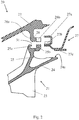
- Fig. 2 shows a guide vane arrangement 20 according to the invention in the not yet assembled state, specifically in an axial section (sectional side view).
- the guide vane arrangement 20 has a guide vane segment 21 and a housing part 22, a section of which is shown in each case.
- a rear guide vane hook 25 is arranged on the outer shroud 24 and engages with one another in a form-fitting manner with a housing hook 26 of the housing part 22.
- Fig. 3 shows the interlocking parts of the guide vane hook 25, the housing hook 26, and the securing element 27.
- Fig. 4 which shows the assembled state.
- a front wall 25 A and a rear wall 25 B of the guide vane hook 25 form a groove 31 Figure 3 the observation plane lies in this groove and the view falls onto the rear wall 25 B.
- an annular section 26 A of the housing hook 26 is held axially.
- the rear wall 25B is interrupted in a second circumferential segment 30B.
- the housing hook 26 engages with a cam 26 B projecting axially to the rear on the ring section 26 A.
- the cam 26 B extends behind the plane of the drawing.
- the rear wall 25 B is again present in a third circumferential segment 30 C, so that the cam 26 B and thus the housing part 22 are secured circumferentially.
- the arrangement according to the invention realizes an axial and at the same time circumferential securing, without separate pins or retaining rings etc.
- the rear wall 25 B is interrupted again in a fourth circumferential segment 30 D, with no cam being arranged in this further interruption 33. It serves the mechanical relief with regard to the mechanical stresses generated by temperature gradients, cf. the introduction to the description in detail.
- the rear wall 25 B is in turn present in a fifth circumferential segment 30 E, the wall regions 25 BA and 25 BE secure the guide vane segment 21 against rotation about the vertical axis.
- the securing element 27 forms with a section 27 A a U-shape which is open towards the front and which, when assembled, engages around the guide vane hook 25 (in particular the rear wall 25 B) and the housing hook 26 (the ring section 26 A and the cam 26 B) and together radially
- the securing element 27 also has a cam 27 B which is arranged in the interruption 32 in the second circumferential segment 30 B and creates circumferential securing.
- the securing element 27 has a sealing section 27 C, which bears on an outer surface 24 A of the outer shroud 24, bordering on the rear edge thereof, and provides a shield to the hot gas duct.
Landscapes
- Engineering & Computer Science (AREA)
- Mechanical Engineering (AREA)
- General Engineering & Computer Science (AREA)
- Structures Of Non-Positive Displacement Pumps (AREA)
Abstract
Description
- Die vorliegende Erfindung betrifft eine Leitschaufelanordnung für eine Strömungsmaschine, mit einem Leitschaufelsegment und einem Gehäuseteil.
- Bei der Strömungsmaschine kann es sich bspw. um ein Strahltriebwerk handeln, z. B. um ein Mantelstromtriebwerk. Funktional gliedert sich die Strömungsmaschine in Verdichter, Brennkammer und Turbine. Etwa im Falle des Strahltriebwerks wird angesaugte Luft vom Verdichter komprimiert und in der nachgelagerten Brennkammer mit hinzugemischtem Kerosin verbrannt. Das entstehende Heißgas, eine Mischung aus Verbrennungsgas und Luft, durchströmt die nachgelagerte Turbine und wird dabei expandiert. Die Turbine ist typischerweise in mehrere Module untergliedert, kann also bspw. ein Hochdruck- und ein Niederdruckturbinenmodul aufweisen. Jedes der Turbinenmodule umfasst dann in der Regel mehrere Stufen, wobei jede Stufe aus einem Leitschaufelkranz und einem stromab darauffolgenden Laufschaufelkranz aufgebaut ist. Die vorliegend in Rede stehende Leitschaufelanordnung umfasst zum einen ein Leitschaufelsegment, welches in dem Modul Teil eines entsprechenden Leitschaufelkranzes ist, und zum anderen ein Gehäuseteil radial außerhalb davon, an dem das Leitschaufelsegment befestigt ist.
- Der vorliegenden Erfindung liegt das technische Problem zugrunde, eine besonders vorteilhafte Leitschaufelanordnung anzugeben.
- Dies wird erfindungsgemäß mit der Leitschaufelanordnung gemäß Anspruch 1 gelöst, und zwar durch eine besonders vorteilhafte Ausgestaltung der formschlüssigen Verbindung zwischen Leitschaufelsegment und Gehäuseteil. Zu deren Beschreibung wird auf verschiedene Umfangssegmente Bezug genommen, was sich auf einen Umlauf um die Längsachse der Strömungsmaschine (siehe unten im Detail) bezieht. Im Einzelnen betrifft der vorliegende Gegenstand den Formschluss zwischen einem hinteren Leitschaufelhaken der sich vom Außendeckband des Leitschaufelsegments nach radial außen erhebt, und einem radial innen am Gehäuseteil angeordneten Gehäusehaken.
- Eine erste Besonderheit liegt nun darin, dass der Leitschaufelhaken in einem ersten Umfangssegment eine axial vordere und eine axiale hintere Wand aufweist, die miteinander eine nach radial außen offene Nut bilden. In dieser ist ein Ringabschnitt des Gehäusehakens angeordnet, womit das Leitschaufelsegment und das Gehäuseteil in Axialrichtung lagefixiert sind. Gegenüber einem alternativ denkbaren Lösungsansatz, nämlich dem Vorsehen eines gesonderten Sicherungsrings (der z. B. in einen Einstich im Gehäuseteil greifen würde, siehe unten im Detail), kann der erfindungsgemäße Ansatz bereits aufgrund einer geringeren Zahl an Einzelteilen vorteilhaft sein. Die Axialfixierung ergibt sich integral aus der Form des hinteren Leitschaufelhakens selbst, der in einem Axialschnitt betrachtet mit der Nut eine U-förmige Aufnahme bildet (in dem ersten Umfangssegment).
- Eine weitere Besonderheit liegt darin, dass diese U-Form nicht durchgehend über den Umlauf gezogen ist, sondern die hintere Wand in einem zweiten Umfangssegment unterbrochen ist. In diese Unterbrechung der hinteren Wand des Leitschaufelhakens greift der Gehäusehaken ein, und zwar mit einem an dem Ringabschnitt nach axial hinten hervortretenden Nocken. Damit wird, wiederum durch die Formgebung der Haken integral, also ohne gesonderten Sicherungsstift oder dergleichen, eine Umfangssicherung des Gehäuseteils geschaffen. Die integrale Ausführung kann nicht nur wegen der verringerten Zahl an Einzelteilen, sondern bspw. auch aus Dichtigkeitsgründen von Vorteil sein. Ein gesondert eingesetzter Sicherungsstift würde nämlich bspw. eine Schlitzung erfordern, was letztlich auch thermisch induzierte Schäden begünstigen könnte. Ferner kann der axial nach hinten hervortretenden Nocken bspw. auch insoweit von Vorteil sein, als er beim Zusammenbau des Moduls, der typischerweise von vorne nach hinten erfolgt, nach hinten sichtbar und somit einer optischen Kontrolle zugänglich ist (anders als bspw. ein an der Vorderseite angeordnetes Formschlusselement).
- Bevorzugte Ausgestaltungen finden sich in den abhängigen Ansprüchen und der gesamten Beschreibung, wobei bei der Darstellung der Merkmale nicht immer im Einzelnen zwischen Vorrichtungs-, Verfahrens- bzw. Verwendungsaspekten unterschieden wird; jedenfalls implizit ist die Offenbarung hinsichtlich sämtlicher Anspruchskategorien zu lesen. Sie betrifft also insbesondere stets sowohl die Leitschaufelanordnung als auch ein Turbinenmodul mit einer solchen bzw. entsprechende Verwendungen.
- Generell bezieht sich im Rahmen dieser Offenbarung "axial" auf die Längsachse des Turbinenmoduls, mithin also die Längsachse der Strömungsmaschine, die bspw. mit einer Drehachse der Rotoren zusammenfällt. "Radial" betrifft die dazu senkrechten, davon weg weisenden Radialrichtungen, und ein "Umlauf" bzw. "umlaufend" oder die "Umlaufrichtung" betreffen die Drehung um die Längsachse (ohne Unterscheidung, ob links- oder rechtsdrehend). "Vorne" und "hinten" beziehen sich jeweils auf jene axiale Richtung, in welcher der Druck abnimmt, "vorne" ist also die druckhöhere und "hinten" die druckniedere Seite. Im Falle des Verdichters nimmt der Druck in Strömungsrichtung des Verdichtergases zu, also in entgegengesetzter Richtung ab, sodass das Verdichtergas "hintere" vor "vorderen" Teilen passiert. Im bevorzugten Fall der Turbine nimmt der Druck in Strömungsrichtung ab, passiert das Heißgas also "vordere" Teile axial vor "hinteren" Teilen ("vorne" meint dann also stromauf und "hinten" stromab).
- "Ein" und "eine" sind im Rahmen dieser Offenbarung ohne ausdrücklich gegenteilige Angabe als unbestimmte Artikel und damit immer auch als "mindestens ein" bzw. "mindestens eine" zu lesen. Es kann also bspw. das Leitschaufelsegment als sogenanntes Mehrfachsegment auch mehrere Leitschaufeln aufweisen, andererseits sind aber auch Leitschaufelsegmente mit jeweils einer einzigen Leitschaufel möglich.
- Vorstehend wurden bereits die Vorteile der integralen Axialsicherung gegenüber einem gesonderten Sicherungsring diskutiert. Ein solcher wäre als in das Gehäuseteil selbst eingesetztes Element auch hinsichtlich der thermischen bzw. thermomechanischen Belastung des Leitschaufelhakens nachteilig. Es wäre nämlich auch die radiale Trennfläche zwischen Leitschaufelhaken und Gehäuse entsprechend weit nach radial außen gesetzt, würde also der radiale Temperaturgradient zwischen Außendeckband und Gehäuse im Wesentlichen ausschließlich über den Leitschaufelhaken anfallen, was für diesen eine entsprechend große Belastung bedeutet und Versagensursache sein kann. Mit der erfindungsgemäßen Anordnung des nach radial innen hervortretenden Gehäusehakens lässt sich die radiale Trennfläche zwischen Leitschaufel- und Gehäusehaken hingegen freier platzieren. Insbesondere ist eine Anordnung derart möglich, dass sich der Temperaturgradient auf den Leitschaufelhaken einerseits und den Gehäusehakens andererseits verteilt.
- Nochmals zu der Formgebung von Leitschaufel- und Gehäusehaken: soweit der Leitschaufelhaken in dem ersten Umfangssegment eine U-Form bildet, ist diese dann in dem zweiten Umfangssegment unterbrochen, liegt dort also bspw. eine L-Form vor. Im Allgemeinen könnte die hintere Wand, also der hintere Schenkel der U-Form, im Bereich der Unterbrechung z. B. auch nur radial verkürzt sein (also nicht vollständig entfernt), womit gleichwohl ein in Umlauf- bzw. Umfangsrichtung gesicherter Eingriff des Gehäusehakens möglich wäre. Bevorzugt liegt jedoch im zweiten Umfangssegment eine L-Form vor, was sich (wie auch die U-Form) auf einen Axialschnitt bezieht, also auf eine Schnittebene, welche die Längsachse beinhaltet.
- In bevorzugter Ausgestaltung ist der Ringabschnitt des Leitschaufelhakens dann in einem dritten Umfangssegment wieder zwischen der vorderen und der hinteren Wand des Leitschaufelhakens axial gehalten. Damit ist auch der nach axial hinten hervortretenden Nocken des Gehäusehakens in beiden Umfangsrichtungen gesichert. Das erste, zweite und dritte Umfangssegment folgen in einer der Umfangs- bzw. Umlaufrichtungen (egal ob links- oder rechtsherum) in der Reihenfolge ihrer Benennung aufeinander (was bevorzugt auch für ein viertes bzw. fünftes Umfangssegment gilt)
- In bevorzugter Ausgestaltung ist die hintere Wand mit einer weiteren Unterbrechung vorgesehen, und zwar in einem vierten Umfangssegment (welches auf das dritte folgt). Die hintere Wand ist dann also nur in dem ersten und dem dritten Umfangssegment vorgesehen (und gegebenenfalls in einem vierten), ist also in anderen Worten in Umlaufrichtung auf vergleichsweise kleine Bereiche beschränkt. Insgesamt kann die hintere Wand dann mit der Beschränkung auf die fraglichen Bereiche gewissermaßen lokal nasen- bzw. nockenförmig ausgebildet sein. Dies kann z. B. insoweit von Vorteil sein, als sich damit das Risiko von thermisch bedingten Schäden verringern lässt. Dies betrifft einen etwaigen axialen Temperaturgradienten, der durch diese Maßnahme zwar an sich nicht verringert wird (dazu wird bevorzugt ein Sicherungselement mit Dichtabschnitt vorgesehen, siehe unten), der dort bildlich gesprochen auf weniger Material wirken kann, sodass die thermisch induziert aufgebauten Kräfte kleiner sind.
- Dieser Vorteil der weiteren Unterbrechung kommt auch darin zum Ausdruck, dass in dieser bevorzugt kein weiterer Nocken des Gehäusehakens angeordnet ist. Anders als die Unterbrechung im zweiten Umfangssegment, welche die Umfangssicherung schafft, motiviert sich die weitere Unterbrechung über die Verringerung thermisch induzierter Spannungen und auch über eine Gewichtsreduzierung. Bezogen auf eine in Umlaufrichtung genommene Erstreckung des Außendeckbands des Leitschaufelsegments kann sich das vierte Umfangssegment (mit der weiteren Unterbrechung) bspw. über einen deutlich größeren Anteil als die anderen Umfangssegmente erstrecken; es kann sich bspw. über mindestens 30 %, 40 % bzw. 50 % der Erstreckung des Außendeckbands erstrecken (möglichen Obergrenzen können z. B. bei höchstens 80 % bzw. 70 % liegen).
- Bei einer bevorzugten Ausführungsform ist dann in einem fünften Umfangssegment, welches auf das vierte und damit die weitere Unterbrechung folgt, wiederum eine nach radial außen offene Nut ausgebildet. In einem Axialschnitt betrachtet bildet der Leitschaufelhaken in dem fünften Umfangssegment also wiederum eine U-Form, in welcher der Ringabschnitt des Gehäusehakens axial gehalten ist.
- In bevorzugter Ausgestaltung grenzen das erste und das fünfte Umfangssegment jeweils an ein umlaufseitiges Ende des Außendeckbands (die Enden liegen in Umlaufrichtung einander entgegengesetzt). Dies kann bspw. auch insoweit von Vorteil, als das Leitschaufelsegment damit (zusammengesetzt mit umlaufend benachbarten Leitschaufelsegmenten) gegen eine Drehung um eine Hochachse gesichert ist.
- Wenngleich die hintere Wand bevorzugt mehrfach unterbrochen ist, ist die vordere Wand des Leitschaufelhakens in bevorzugter Ausgestaltung ohne Unterbrechung vorgesehen. Sie erstreckt sich also zwischen den einander entgegengesetzten umlaufseitigen Enden des Leitschaufelhakens durchgehend, also unterbrechungsfrei. Damit ist auch die entsprechende Anlagefläche zwischen dem Ringabschnitt des Gehäusehakens und der vorderen Wand des Leitschaufelhakens unterbrechungsfrei, was z. B. hinsichtlich der Dichtigkeit von Vorteil ist. Besagte Anlagefläche hat generell einen "axialen" Anteil, der das Leitschaufelsegment gegen einen Axialversatz nach hinten hält (die entsprechende Anlagefläche hat im Axialschnitt betrachtet typischerweise eine radiale Erstreckung). Ferner gibt es einen "radialen" Anteil (Anlage am Nutgrund). Da auf das Leitschaufelsegment "nach hinten" vergleichsweise große Kräfte wirken, ist die unterbrechungsfreie Anlage auch in mechanischer Hinsicht von Vorteil.
- In bevorzugter Ausgestaltung gibt es ein zusätzliches Sicherungselement, welches den Leitschaufelhaken und den Gehäusehakens zumindest segmentweise umschließt. Dazu bildet das Sicherungselement eine nach vorne offene U-Form (im Axialschnitt betrachtet) und wird es von hinten auf die zusammengesetzten Haken aufgeschoben. Bevorzugt ist das Sicherungselement ein Mantelringsegment. Mit der nach vorne gewandten U-Form hält es die Haken dann hinsichtlich der radialen Richtung zusammen, insbesondere im unbelasteten Zustand (wenn das Leitschaufelsegment nicht aufgrund des Betriebsdrucks nach radial außen gedrückt wird).
- In bevorzugter Ausgestaltung bildet der Gehäusehakens mit dem Ringabschnitt in einem Axialschnitt betrachtet eine L-Form, und zwar nicht nur mit dem Nocken im zweiten Umfangssegment, sondern auch (bereits) mit dem Ringabschnitt im ersten Umfangssegment (mit einem im Vergleich kürzeren Schenkel dort). Es ist also auch dort eine L-Form ausgebildet, wo der Ringabschnitt axial zwischen vorderer und hinterer Wand gehalten ist. Dabei weist der liegende Schenkel der L-Form nach hinten und wird von dem Sicherungselement nach radial außen eingefasst.
- Bei einer bevorzugten Ausführungsform weist das Sicherungselement einen Dichtabschnitt auf, der an einer nach radial außen weisenden Außenwandfläche des Außendeckbands an liegt. Im Axialschnitt betrachtet erstreckt sich dieser Dichtabschnitt von der U-Form weg nach axial hinten, also gewissermaßen entgegengesetzt zu den Schenkeln der U-Form. Dabei setzt der Dichtabschnitt idealerweise am radial inneren Schenkel der U-Form an, was eine gute Abschirmung des radial außerhalb liegenden Verbindungsbereichs zwischen Gehäuse- und Leitschaufelhaken schafft. Es lässt sich also insbesondere der U-förmige bzw. dann auch unterbrochene Bereich zum Heißgaskanal hin abschirmen, was Temperaturgradienten reduzieren helfen kann. Insoweit kann sich eine vorteilhafte Wechselwirkung mit den vorstehend geschilderten Maßnahmen (Verringerung der Materialmenge, auf welche Temperaturgradienten wirken) ergeben, als die verbleibenden Belastungen in Summe auf ein unkritisches Niveau gebracht werden können.
- Vorzugsweise bildet das Sicherungselement eine Gaskanalbegrenzung, welche radial an Laufschaufeln angrenzt, die zum Leitschaufelsegment axial benachbart angeordnet sind. Dabei kann das Sicherungselement zudem auch einen Einlaufbelag, bspw. in Form einer Honigwabendichtung, für die Laufschaufeln aufweisen. Dadurch können mit vorteilhaft wenig und leicht zu montierenden Teilen Leitschaufeln am Gehäuse befestigt werden und gleichzeitig eine bündig und dicht anschließende Gaskanalbegrenzung bzw. -Innenwandung im axialen Bereich der nachfolgenden Laufschaufeln bereitgestellt werden.
- Das Sicherungselement mit integralen Dichtabschnitt ist auch hinsichtlich der Integration unterschiedlicher Funktionen von Vorteil (Axialsicherung und Radialfixierung), was Einzelteile reduzieren helfen kann. Das Sicherungselement kann im Allgemeinen bspw. auch ein Frästeil sein, bevorzugt wird es aus Blech gestanzt bzw. gebogen.
- In bevorzugter Ausgestaltung liegt der Dichtabschnitt in einem Bereich der Außenwandfläche des Außendeckband an, der an dessen Hinterkante grenzt. Die Dichtstelle ist also soweit möglich nach axial hinten gezogen, was auch hinsichtlich der Abschirmung von Vorteil sein kann.
- Bei einer bevorzugten Ausführungsform weist das Sicherungselement einen nach axial vorne hervortretenden Nocken auf, der gemeinsam mit dem Nocken des Gehäusehakens in der Unterbrechung der hinteren Wand des Leitschaufelhakens angeordnet ist. Die beiden Nocken sind also radial aufeinander gesetzt, bevorzugt liegt der Nocken des Sicherungselements radial innen und jener des Gehäuseteils radial außen. Damit wird also mit derselben Unterbrechung, die auch der Umfangssicherung des Gehäuseteils dient, das Sicherungselement in Umfangsrichtung gesichert. Auch insoweit ist kein gesonderter Sicherungsstift oder dergleichen erforderlich.
- Insgesamt kann das Sicherungselement mit seinen unterschiedlichen Abschnitten (U-Form mit Dichtabschnitt und gegebenenfalls weiterem Schenkel) eine nach radial außen offene Aufnahme bilden, in welche ein Dämmmaterial eingesetzt werden kann. Der erfindungsgemäße Gegenstand eröffnet auch weitere Möglichkeiten, es kann nämlich bspw. vor den Haken ein Hitzeschild radial zwischen Außendeckband und Gehäuseteil angeordnet sein (was aber an sich bekannt ist). Ein solches Hitzeschild kann bspw. am Gehäusehaken montiert sein.
- Die Erfindung betrifft auch ein Turbinenmodul mit einer vorliegend offenbarten Leitschaufelanordnung. In einem jeweiligen Leitschaufelkranz können dabei umlaufend aufeinander folgend mehrere entsprechend ausgestaltete Leitschaufelanordnungen vorgesehen sein. Dabei ist insbesondere auch eine Ausgestaltung dahingehend möglich, dass mit einem Umfangsversatz Spalte verdeckt werden. Es kann sich bspw. das Sicherungselement mit der U-Form über die Verbindungsstelle zwischen zwei Außendeckbändern hinweg erstrecken.
- Die Erfindung betrifft ferner auch die Verwendung eines solchen Turbinenmoduls bzw. einer vorliegend offenbarten Leitschaufelanordnung in einer Strömungsmaschine, insbesondere in einem Strahltriebwerk, bspw. einem Mantelstromtriebwerk.
- Im Folgenden wird die Erfindung anhand eines Ausführungsbeispiels näher erläutert, wobei die einzelnen Merkmale im Rahmen der nebengeordneten Ansprüche auch in anderer Kombination erfindungswesentlich sein können und auch weiterhin nicht im Einzelnen zwischen den unterschiedlichen Anspruchskategorien unterschieden wird.
- Im Einzelnen zeigt
- Figur 1
- ein Strahltriebwerk in einem Axialschnitt;
- Figur 2
- die Teile einer erfindungsgemäßen Leitschaufelanordnung in einer teilweise geschnittenen Seitenansicht, und zwar vor dem Zusammensetzen;
- Figur 3
- eine Axialansicht zu
Figur 2 ; - Figur 4
- die Teile gemäß
Figur 2 im zusammengesetzten Zustand. -
Fig. 1 zeigt eine Strömungsmaschine 1, konkret ein Mantelstromtriebwerk, in einem Axialschnitt. Die Strömungsmaschine 1 gliedert sich funktional in Verdichter 1 A, Brennkammer 1 B und Turbine 1 C. Sowohl der Verdichter 1 A als auch die Turbine 1 C sind jeweils aus mehreren Stufen aufgebaut, jede Stufe setzt sich aus einem Leit- und einem darauffolgenden Laufschaufelkranz zusammen. Die Laufschaufelkränze rotieren im Betrieb um die Längsachse 2 der Strömungsmaschine 1. Im Verdichter 1 A wird die angesaugte Luft komprimiert, und dann in der nachgelagerten Brennkammer 1 B mit hinzugemischtem Kerosin verbrannt. Das Heißgas durchströmt den Heißgaskanal 3 und treibt dabei die Laufschaufelkränze an, die um die Längsachse 2 rotieren. -
Fig. 2 zeigt eine erfindungsgemäße Leitschaufelanordnung 20 im noch nicht zusammengesetzten Zustand, und zwar in einem Axialschnitt (geschnittene Seitenansicht). Die Leitschaufelanordnung 20 weist ein Leitschaufelsegment 21 sowie ein Gehäuseteil 22 auf, wovon jeweils ein Ausschnitt dargestellt ist. Konkret ist im Falle des Leitschaufelsegments 21 ein Teil der Leitschaufel 23 sowie das radial außerhalb davon angeordneten Außendeckband 24 zu erkennen. Am Außendeckband 24 ist ein hinterer Leitschaufelhaken 25 angeordnet, der formschlüssig mit einem Gehäusehaken 26 des Gehäuseteils 22 ineinander greift. Ferner gibt es ein Sicherungselement 27, dass der Radialsicherung und zugleich Abdichtung dient (siehe unten im Detail). - Im Folgenden wird ergänzend auch auf
Fig. 3 verwiesen, die die ineinandergreifenden Teile des Leitschaufelhakens 25, des Gehäusehakens 26, sowie das Sicherungselement 27 zeigt. Ferner wird aufFig. 4 verwiesen, die den zusammengesetzten Zustand zeigt. In einem ersten Umfangssegment 30 A bilden eine vordere Wand 25 A und eine hintere Wand 25 B des Leitschaufelhakens 25 eine nach radial außen offene Nut 31. InFigur 3 liegt die Beobachtungsebene in dieser Nut und fällt der Blick auf die hintere Wand 25 B. In der Nut 31 ist ein Ringabschnitt 26 A des Gehäusehakens 26 axial gehalten. - In einem zweiten Umfangssegment 30 B ist die hintere Wand 25 B unterbrochen. In diese Unterbrechung 32 greift der Gehäusehaken 26 mit einem an dem Ringabschnitt 26 A nach axial hinten hervortretenden Nocken 26 B ein. Dessen Position ist in
Figur 3 strichliert angedeutet (der Nocken 26 B erstreckt sich hinterhalb der Zeichenebene). In einem dritten Umfangssegment 30 C ist die hintere Wand 25 B wieder vorhanden, sodass der Nocken 26 B und damit das Gehäuseteil 22 umfangsgesichert ist. - In dieser Hinsicht ist mit der erfindungsgemäßen Anordnung eine Axial- und zugleich Umfangssicherung realisiert, und zwar ohne gesonderte Stifte oder Sicherungsringe etc. Hinsichtlich der Vorteile wird ausdrücklich auf die Beschreibungseinleitung verwiesen.
- In einem vierten Umfangssegment 30 D ist die hintere Wand 25 B erneut unterbrochen, wobei in dieser weiteren Unterbrechung 33 kein Nocken angeordnet ist. Sie dient der mechanischen Entlastung hinsichtlich der durch Temperaturgradienten erzeugten mechanischen Spannungen, vgl. die Beschreibungseinleitung im Einzelnen.
- In einem fünften Umfangssegment 30 E ist die hintere Wand 25 B wiederum vorhanden, die Wandbereiche 25 BA und 25 BE sichern das Leitschaufelsegment 21 gegen eine Drehung um die Hochachse.
- Das Sicherungselement 27 bildet mit einem Abschnitt 27 A eine nach vorne offene U-Form, welche im zusammengesetzten Zustand den Leitschaufelhaken 25 (insbesondere die hintere Wand 25 B) und den Gehäusehaken 26 (den Ringabschnitt 26 A und den Nocken 26 B umgreift und radial beisammen hält. Das Sicherungselement 27 weist ferner einen Nocken 27 B auf, der in der Unterbrechung 32 im zweiten Umfangssegment 30 B angeordnet ist und eine Umfangssicherung schafft.
- Ferner weist das Sicherungselement 27 einen Dichtabschnitt 27 C auf, der an einer Außenfläche 24 A des Außendeckbands 24, an dessen Hinterkante grenzend, anliegt und eine Abschirmung zum Heißgaskanal hin schafft.
BEZUGSZEICHENLISTE Strömungsmaschine 1 Verdichter 1 A Brennkammer 1 B Turbine 1 C Längsachse 2 Heißgaskanal 3 Leitschaufel 20 Leitschaufelsegment 21 Gehäuseteil 22 Leitschaufel 23 Außendeckband 24 Außenfläche 24 A Leitschaufelhaken (hinterer) 25 Vordere Wand 25 A Hintere Wand 25 B Wandbereich 25 BA, BC, BE Gehäusehaken 26 Ringabschnitt 26 A Nocken 26 B Sicherungselement 27 U-förmiger Abschnitt 27 A Nocken 27 B Dichtabschnitt 27 C Umfangssegmente 30 Erstes 30 A Zweites 30 B Drittes 30 C Viertes 30 D Fünftes 30 E Unterbrechung 32 Weitere Unterbrechung 33
Claims (15)
- Leitschaufelanordnung (20) für eine Strömungsmaschine (1), mit
einem Leitschaufelsegment (21) und einem Gehäuseteil (22), die aneinander befestigt sind,
wozu ein hinterer Leitschaufelhaken (25), der sich bezogen auf eine Längsachse (2) der Strömungsmaschine (1) von einem Außendeckband (24) des Leitschaufelsegments (21) nach radial außen erhebt, und ein Gehäusehaken (26), der radial innen umlaufend an dem Gehäuseteil (22) angeordnet ist, formschlüssig ineinandergreifen,
wobei, in einem ersten Umfangssegment (30 A) der Leitschaufelanordnung (20), der Leitschaufelhaken (25) eine vordere Wand (25 A) und eine hintere Wand (25 B) aufweist und damit eine nach radial außen offene Nut (31) bildet, in welcher ein Ringabschnitt (26 A) des Gehäusehakens (26) angeordnet und axial gehalten ist,
und wobei, in einem zweiten Umfangssegment (30 B) der Leitschaufelanordnung (20), die hintere Wand (25 B) des Leitschaufelhakens (25) mit einer Unterbrechung (32) vorgesehen ist und an dem Ringabschnitt (26 A) des Gehäusehakens (26) ein nach axial hinten hervortretender Nocken (26 B) angeordnet ist, der sich nach axial hinten in die Unterbrechung (32) der hinteren Wand (25 B) hinein erstreckt und darin zur Umlauffixierung gehalten ist. - Leitschaufelanordnung (20) nach Anspruch 1, bei welcher, in einem dritten Umfangssegment (30 C) der Leitschaufelanordnung (20), welches auf das zweite Umfangssegment (30 B) mit der Unterbrechung (32) folgt, die vordere Wand (25 A) zusammen mit der hinteren Wand (25 B) wieder eine nach radial außen offene Nut (31) bildet, in welcher der Ringabschnitt (26 A) des Gehäusehakens (26) angeordnet und axial gehalten ist.
- Leitschaufelanordnung (20) nach Anspruch 2, bei welcher, in einem vierten Umfangssegment (30 D) der Leitschaufelanordnung (20), welches auf das dritte Umfangssegment (30 C) mit der Unterbrechung (32) folgt, die hintere Wand (25 B) des Leitschaufelhakens (25) mit einer weiteren Unterbrechung (33) vorgesehen ist.
- Leitschaufelanordnung (20) nach Anspruch 3, bei welcher die weitere Unterbrechung (33) gehäusehakenfrei ist, darin also kein weiterer Nocken des Gehäusehakens (26) angeordnet ist.
- Leitschaufelanordnung (20) nach Anspruch 3 oder 4, bei welcher, in einem fünften Umfangssegment (30 E) der Leitschaufelanordnung (20), welches auf das vierte Umfangssegment (30 D) mit der weiteren Unterbrechung (33) folgt, die vordere Wand (25 A) zusammen mit der hinteren Wand (25 B) wieder eine nach radial außen offene Nut (31) bildet, in welcher der Ringabschnitt (26 A) des Gehäusehakens (26) angeordnet und axial gehalten ist.
- Leitschaufelanordnung (20) nach Anspruch 5, bei welcher das fünfte Umfangssegment (30 E) an ein umlaufseitiges Ende des Außendeckbands (24) grenzt.
- Leitschaufelanordnung (20) nach einem der vorstehenden Ansprüche, bei welcher das erste Umfangssegment (30 A) an ein umlaufseitiges Ende des Außendeckbands (24) grenzt.
- Leitschaufelanordnung (20) nach einem der vorstehenden Ansprüche, bei welchem sich die vordere Wand (25 A) des Leitschaufelhakens (25) unterbrechungsfrei durchgehend von einem umlaufseitigen Ende des Leitschaufelsegments (21) zum entgegengesetzten umlaufseitigen Ende erstreckt.
- Leitschaufelanordnung (20) nach einem der vorstehenden Ansprüche mit einem Sicherungselement (27), welches in einem Axialschnitt betrachtet eine nach vorne offene U-Form bildet, welche den Leitschaufelhaken (25) und den Gehäusehaken (26) zumindest segmentweise umschließt.
- Leitschaufelanordnung (20) nach Anspruch 9, bei welcher, in einem Axialschnitt in dem ersten Umfangssegment (30 A) betrachtet, der Gehäusehaken (26) mit dem Ringabschnitt (26 A) eine L-Form mit einem nach hinten orientierten Schenkel bildet, der von dem Sicherungselement (27) nach radial außen eingefasst wird.
- Leitschaufelanordnung (20) nach Anspruch 9 oder 10, bei welcher das Sicherungselement (27) einen Dichtabschnitt (27 C) aufweist, der an einer nach radial außen weisenden Außenfläche (24 A) des Außendeckbands (24) des Leitschaufelsegments (21) anliegt, und/oder
bei welcher das Sicherungselement (27) eine Gaskanalbegrenzung bildet, welche radial an dem Leitschaufelsegment (21) benachbarte Laufschaufeln angrenzt, insbesondere einen Einlaufbelag für die Laufschaufeln aufweist. - Leitschaufelanordnung (20) nach Anspruch 11, bei welcher der Dichtabschnitt (27 C) des Sicherungselements (27) jedenfalls auch in einem Bereich der Außenfläche (24 A) des Außendeckbands (24) anliegt, der an die Hinterkante des Außendeckbands (24) grenzt
- Leitschaufelanordnung (20) nach einem der vorstehenden Ansprüche 9 bis 12, bei welcher, in dem zweiten Umfangssegment (30 B) der Leitschaufelanordnung (21), an dem Sicherungselement (27) ein nach axial vorne hervortretender Nocken (27 B) vorgesehen ist, der gemeinsam mit dem Nocken (26 B) des Gehäusehakens (26) in der Unterbrechung (32) der hinteren Wand (25 B) des Leitschaufelhakens (25) angeordnet ist.
- Turbinenmodul mit einer Leitschaufelanordnung (20) nach einem der vorstehenden Ansprüche.
- Verwendung einer Leitschaufelanordnung (20) nach einem der Ansprüche 1 bis 13 oder eines Turbinenmoduls gemäß Anspruch 14 in einer Strömungsmaschine (1), insbesondere in einem Strahltriebwerk.
Applications Claiming Priority (1)
| Application Number | Priority Date | Filing Date | Title |
|---|---|---|---|
| DE102018210597.9A DE102018210597A1 (de) | 2018-06-28 | 2018-06-28 | Leitschaufelanordnung für eine strömungsmaschine |
Publications (2)
| Publication Number | Publication Date |
|---|---|
| EP3587750A1 true EP3587750A1 (de) | 2020-01-01 |
| EP3587750B1 EP3587750B1 (de) | 2021-06-02 |
Family
ID=67060320
Family Applications (1)
| Application Number | Title | Priority Date | Filing Date |
|---|---|---|---|
| EP19182166.9A Active EP3587750B1 (de) | 2018-06-28 | 2019-06-25 | Leitschaufelanordnung für eine strömungsmaschine |
Country Status (4)
| Country | Link |
|---|---|
| US (1) | US11156115B2 (de) |
| EP (1) | EP3587750B1 (de) |
| DE (1) | DE102018210597A1 (de) |
| ES (1) | ES2877577T3 (de) |
Families Citing this family (1)
| Publication number | Priority date | Publication date | Assignee | Title |
|---|---|---|---|---|
| US12529322B1 (en) | 2024-11-08 | 2026-01-20 | Pratt & Whitney Canada Corp. | Gas turbine engine stator vane stage |
Citations (3)
| Publication number | Priority date | Publication date | Assignee | Title |
|---|---|---|---|---|
| US20020048512A1 (en) * | 2000-10-19 | 2002-04-25 | Snecma Moteurs | Linking arrangement of a turbine stator ring to a support strut |
| US20110056055A1 (en) * | 2008-05-16 | 2011-03-10 | Snecma | Member for locking ring sectors on a turbine engine casing, including radial passages for gripping same |
| US20160290168A1 (en) * | 2015-04-01 | 2016-10-06 | General Electric Company | Turbine exhaust frame and method of vane assembly |
Family Cites Families (8)
| Publication number | Priority date | Publication date | Assignee | Title |
|---|---|---|---|---|
| US6412149B1 (en) * | 1999-08-25 | 2002-07-02 | General Electric Company | C-clip for shroud assembly |
| FR2800797B1 (fr) * | 1999-11-10 | 2001-12-07 | Snecma | Assemblage d'un anneau bordant une turbine a la structure de turbine |
| JP4269829B2 (ja) * | 2003-07-04 | 2009-05-27 | 株式会社Ihi | シュラウドセグメント |
| FR2887920B1 (fr) * | 2005-06-29 | 2010-09-10 | Snecma | Dispositif de fixation de secteurs d'anneau sur un carter de turbine |
| US7452183B2 (en) * | 2005-08-06 | 2008-11-18 | General Electric Company | Thermally compliant turbine shroud assembly |
| US8118547B1 (en) | 2009-04-15 | 2012-02-21 | Florida Turbine Technologies, Inc. | Turbine inter-stage gap cooling arrangement |
| GB0909470D0 (en) | 2009-06-03 | 2009-07-15 | Rolls Royce Plc | A guide vane assembly |
| EP3147457B1 (de) | 2015-09-22 | 2019-01-30 | Ansaldo Energia Switzerland AG | Gasturbine mit einer leitschaufel und einem leitschaufelträger |
-
2018
- 2018-06-28 DE DE102018210597.9A patent/DE102018210597A1/de not_active Withdrawn
-
2019
- 2019-06-25 ES ES19182166T patent/ES2877577T3/es active Active
- 2019-06-25 EP EP19182166.9A patent/EP3587750B1/de active Active
- 2019-06-27 US US16/454,520 patent/US11156115B2/en active Active
Patent Citations (3)
| Publication number | Priority date | Publication date | Assignee | Title |
|---|---|---|---|---|
| US20020048512A1 (en) * | 2000-10-19 | 2002-04-25 | Snecma Moteurs | Linking arrangement of a turbine stator ring to a support strut |
| US20110056055A1 (en) * | 2008-05-16 | 2011-03-10 | Snecma | Member for locking ring sectors on a turbine engine casing, including radial passages for gripping same |
| US20160290168A1 (en) * | 2015-04-01 | 2016-10-06 | General Electric Company | Turbine exhaust frame and method of vane assembly |
Also Published As
| Publication number | Publication date |
|---|---|
| US20200003065A1 (en) | 2020-01-02 |
| DE102018210597A1 (de) | 2020-01-02 |
| EP3587750B1 (de) | 2021-06-02 |
| US11156115B2 (en) | 2021-10-26 |
| ES2877577T3 (es) | 2021-11-17 |
Similar Documents
| Publication | Publication Date | Title |
|---|---|---|
| EP3056813B1 (de) | Abdichtung eines randspalts zwischen effusionsschindeln einer gasturbinenbrennkammer | |
| DE102004024683B4 (de) | Dichtungssystem für horizontale Verbindungsstellen von Zwischenböden von Dampfturbinen | |
| EP2044293B1 (de) | Gasturbine mit einem mantelringsegment, das einen rezirkulationskanal umfasst | |
| DE1476795A1 (de) | Duesen-Zwischenboden,insbesondere fuer Gasturbinen | |
| EP3587739A1 (de) | Mantelringanordnung für eine strömungsmaschine | |
| EP2918778B1 (de) | Verfahren zum auslegen einer turbine | |
| DE112018000772B4 (de) | Dampfturbine, die in der lage ist, erosion und wirkungsgradverschlechterung zu unterdrücken | |
| EP2428647B1 (de) | Übergangsbereich für eine Brennkammer einer Gasturbine | |
| EP3587750B1 (de) | Leitschaufelanordnung für eine strömungsmaschine | |
| EP2787178B1 (de) | Leitschaufelanordnung | |
| EP1995413A1 (de) | Spaltdichtung bei Schaufeln einer Turbomaschine | |
| CH714847B1 (de) | Verschalung für einen Turbolader und Turbolader. | |
| EP2526263B1 (de) | Gehäusesystem für eine axialströmungsmaschine | |
| EP3581760B1 (de) | Schaufelblatt für eine thermische strömungsmaschine | |
| DE102018202888A1 (de) | Leitschaufelblatt für den Heissgaskanal einer Strömungsmaschine | |
| EP2474744A1 (de) | Ringförmiger Strömungskanal für einen Axialverdichter | |
| WO2010088881A1 (de) | Abdichtvorrichtung an dem schaufelschaft einer rotorstufe einer axialen strömungsmaschine | |
| EP3587741B1 (de) | Segmentring zur montage in einer strömungsmaschine | |
| EP3628030B1 (de) | Verfahren zum instandhalten einer strömungsmaschine | |
| CH711975A2 (de) | Radialturbine, Turbolader und Einsatzstück für ein Turbinengehäuse der Radialturbine. | |
| EP2831379B1 (de) | Trägerring | |
| DE102007053135A1 (de) | Gasturbinenbauteil, insbesondere Flugtriebwerksbauteil bzw. Verdichterbauteil | |
| DE60121968T2 (de) | Verfahren zum Herstellen von Dampfturbinen | |
| DE102018118264A1 (de) | Dichtungssystem für eine Rotationsmaschine und Verfahren zur Montage desselben | |
| EP3536913A1 (de) | Innenring für eine turbomaschine und entsprechendes herstellungsverfahren |
Legal Events
| Date | Code | Title | Description |
|---|---|---|---|
| PUAI | Public reference made under article 153(3) epc to a published international application that has entered the european phase |
Free format text: ORIGINAL CODE: 0009012 |
|
| STAA | Information on the status of an ep patent application or granted ep patent |
Free format text: STATUS: THE APPLICATION HAS BEEN PUBLISHED |
|
| AK | Designated contracting states |
Kind code of ref document: A1 Designated state(s): AL AT BE BG CH CY CZ DE DK EE ES FI FR GB GR HR HU IE IS IT LI LT LU LV MC MK MT NL NO PL PT RO RS SE SI SK SM TR |
|
| AX | Request for extension of the european patent |
Extension state: BA ME |
|
| STAA | Information on the status of an ep patent application or granted ep patent |
Free format text: STATUS: REQUEST FOR EXAMINATION WAS MADE |
|
| 17P | Request for examination filed |
Effective date: 20200616 |
|
| RBV | Designated contracting states (corrected) |
Designated state(s): AL AT BE BG CH CY CZ DE DK EE ES FI FR GB GR HR HU IE IS IT LI LT LU LV MC MK MT NL NO PL PT RO RS SE SI SK SM TR |
|
| GRAP | Despatch of communication of intention to grant a patent |
Free format text: ORIGINAL CODE: EPIDOSNIGR1 |
|
| STAA | Information on the status of an ep patent application or granted ep patent |
Free format text: STATUS: GRANT OF PATENT IS INTENDED |
|
| INTG | Intention to grant announced |
Effective date: 20210112 |
|
| GRAS | Grant fee paid |
Free format text: ORIGINAL CODE: EPIDOSNIGR3 |
|
| GRAA | (expected) grant |
Free format text: ORIGINAL CODE: 0009210 |
|
| STAA | Information on the status of an ep patent application or granted ep patent |
Free format text: STATUS: THE PATENT HAS BEEN GRANTED |
|
| REG | Reference to a national code |
Ref country code: CH Ref legal event code: EP |
|
| AK | Designated contracting states |
Kind code of ref document: B1 Designated state(s): AL AT BE BG CH CY CZ DE DK EE ES FI FR GB GR HR HU IE IS IT LI LT LU LV MC MK MT NL NO PL PT RO RS SE SI SK SM TR |
|
| REG | Reference to a national code |
Ref country code: GB Ref legal event code: FG4D Free format text: NOT ENGLISH |
|
| REG | Reference to a national code |
Ref country code: AT Ref legal event code: REF Ref document number: 1398626 Country of ref document: AT Kind code of ref document: T Effective date: 20210615 |
|
| REG | Reference to a national code |
Ref country code: IE Ref legal event code: FG4D Free format text: LANGUAGE OF EP DOCUMENT: GERMAN |
|
| REG | Reference to a national code |
Ref country code: DE Ref legal event code: R096 Ref document number: 502019001532 Country of ref document: DE |
|
| REG | Reference to a national code |
Ref country code: LT Ref legal event code: MG9D |
|
| PG25 | Lapsed in a contracting state [announced via postgrant information from national office to epo] |
Ref country code: BG Free format text: LAPSE BECAUSE OF FAILURE TO SUBMIT A TRANSLATION OF THE DESCRIPTION OR TO PAY THE FEE WITHIN THE PRESCRIBED TIME-LIMIT Effective date: 20210902 Ref country code: FI Free format text: LAPSE BECAUSE OF FAILURE TO SUBMIT A TRANSLATION OF THE DESCRIPTION OR TO PAY THE FEE WITHIN THE PRESCRIBED TIME-LIMIT Effective date: 20210602 Ref country code: HR Free format text: LAPSE BECAUSE OF FAILURE TO SUBMIT A TRANSLATION OF THE DESCRIPTION OR TO PAY THE FEE WITHIN THE PRESCRIBED TIME-LIMIT Effective date: 20210602 Ref country code: LT Free format text: LAPSE BECAUSE OF FAILURE TO SUBMIT A TRANSLATION OF THE DESCRIPTION OR TO PAY THE FEE WITHIN THE PRESCRIBED TIME-LIMIT Effective date: 20210602 |
|
| REG | Reference to a national code |
Ref country code: NL Ref legal event code: MP Effective date: 20210602 |
|
| REG | Reference to a national code |
Ref country code: ES Ref legal event code: FG2A Ref document number: 2877577 Country of ref document: ES Kind code of ref document: T3 Effective date: 20211117 |
|
| PG25 | Lapsed in a contracting state [announced via postgrant information from national office to epo] |
Ref country code: LV Free format text: LAPSE BECAUSE OF FAILURE TO SUBMIT A TRANSLATION OF THE DESCRIPTION OR TO PAY THE FEE WITHIN THE PRESCRIBED TIME-LIMIT Effective date: 20210602 Ref country code: PL Free format text: LAPSE BECAUSE OF FAILURE TO SUBMIT A TRANSLATION OF THE DESCRIPTION OR TO PAY THE FEE WITHIN THE PRESCRIBED TIME-LIMIT Effective date: 20210602 Ref country code: NO Free format text: LAPSE BECAUSE OF FAILURE TO SUBMIT A TRANSLATION OF THE DESCRIPTION OR TO PAY THE FEE WITHIN THE PRESCRIBED TIME-LIMIT Effective date: 20210902 Ref country code: SE Free format text: LAPSE BECAUSE OF FAILURE TO SUBMIT A TRANSLATION OF THE DESCRIPTION OR TO PAY THE FEE WITHIN THE PRESCRIBED TIME-LIMIT Effective date: 20210602 Ref country code: RS Free format text: LAPSE BECAUSE OF FAILURE TO SUBMIT A TRANSLATION OF THE DESCRIPTION OR TO PAY THE FEE WITHIN THE PRESCRIBED TIME-LIMIT Effective date: 20210602 Ref country code: GR Free format text: LAPSE BECAUSE OF FAILURE TO SUBMIT A TRANSLATION OF THE DESCRIPTION OR TO PAY THE FEE WITHIN THE PRESCRIBED TIME-LIMIT Effective date: 20210903 |
|
| PG25 | Lapsed in a contracting state [announced via postgrant information from national office to epo] |
Ref country code: SK Free format text: LAPSE BECAUSE OF FAILURE TO SUBMIT A TRANSLATION OF THE DESCRIPTION OR TO PAY THE FEE WITHIN THE PRESCRIBED TIME-LIMIT Effective date: 20210602 Ref country code: EE Free format text: LAPSE BECAUSE OF FAILURE TO SUBMIT A TRANSLATION OF THE DESCRIPTION OR TO PAY THE FEE WITHIN THE PRESCRIBED TIME-LIMIT Effective date: 20210602 Ref country code: SM Free format text: LAPSE BECAUSE OF FAILURE TO SUBMIT A TRANSLATION OF THE DESCRIPTION OR TO PAY THE FEE WITHIN THE PRESCRIBED TIME-LIMIT Effective date: 20210602 Ref country code: PT Free format text: LAPSE BECAUSE OF FAILURE TO SUBMIT A TRANSLATION OF THE DESCRIPTION OR TO PAY THE FEE WITHIN THE PRESCRIBED TIME-LIMIT Effective date: 20211004 Ref country code: RO Free format text: LAPSE BECAUSE OF FAILURE TO SUBMIT A TRANSLATION OF THE DESCRIPTION OR TO PAY THE FEE WITHIN THE PRESCRIBED TIME-LIMIT Effective date: 20210602 Ref country code: NL Free format text: LAPSE BECAUSE OF FAILURE TO SUBMIT A TRANSLATION OF THE DESCRIPTION OR TO PAY THE FEE WITHIN THE PRESCRIBED TIME-LIMIT Effective date: 20210602 Ref country code: CZ Free format text: LAPSE BECAUSE OF FAILURE TO SUBMIT A TRANSLATION OF THE DESCRIPTION OR TO PAY THE FEE WITHIN THE PRESCRIBED TIME-LIMIT Effective date: 20210602 |
|
| REG | Reference to a national code |
Ref country code: DE Ref legal event code: R097 Ref document number: 502019001532 Country of ref document: DE |
|
| REG | Reference to a national code |
Ref country code: BE Ref legal event code: MM Effective date: 20210630 |
|
| PG25 | Lapsed in a contracting state [announced via postgrant information from national office to epo] |
Ref country code: MC Free format text: LAPSE BECAUSE OF FAILURE TO SUBMIT A TRANSLATION OF THE DESCRIPTION OR TO PAY THE FEE WITHIN THE PRESCRIBED TIME-LIMIT Effective date: 20210602 Ref country code: LU Free format text: LAPSE BECAUSE OF NON-PAYMENT OF DUE FEES Effective date: 20210625 |
|
| PLBE | No opposition filed within time limit |
Free format text: ORIGINAL CODE: 0009261 |
|
| STAA | Information on the status of an ep patent application or granted ep patent |
Free format text: STATUS: NO OPPOSITION FILED WITHIN TIME LIMIT |
|
| PG25 | Lapsed in a contracting state [announced via postgrant information from national office to epo] |
Ref country code: IE Free format text: LAPSE BECAUSE OF NON-PAYMENT OF DUE FEES Effective date: 20210625 Ref country code: DK Free format text: LAPSE BECAUSE OF FAILURE TO SUBMIT A TRANSLATION OF THE DESCRIPTION OR TO PAY THE FEE WITHIN THE PRESCRIBED TIME-LIMIT Effective date: 20210602 |
|
| 26N | No opposition filed |
Effective date: 20220303 |
|
| PG25 | Lapsed in a contracting state [announced via postgrant information from national office to epo] |
Ref country code: AL Free format text: LAPSE BECAUSE OF FAILURE TO SUBMIT A TRANSLATION OF THE DESCRIPTION OR TO PAY THE FEE WITHIN THE PRESCRIBED TIME-LIMIT Effective date: 20210602 |
|
| PG25 | Lapsed in a contracting state [announced via postgrant information from national office to epo] |
Ref country code: IT Free format text: LAPSE BECAUSE OF FAILURE TO SUBMIT A TRANSLATION OF THE DESCRIPTION OR TO PAY THE FEE WITHIN THE PRESCRIBED TIME-LIMIT Effective date: 20210602 Ref country code: BE Free format text: LAPSE BECAUSE OF NON-PAYMENT OF DUE FEES Effective date: 20210630 |
|
| REG | Reference to a national code |
Ref country code: CH Ref legal event code: PL |
|
| PG25 | Lapsed in a contracting state [announced via postgrant information from national office to epo] |
Ref country code: LI Free format text: LAPSE BECAUSE OF NON-PAYMENT OF DUE FEES Effective date: 20220630 Ref country code: CH Free format text: LAPSE BECAUSE OF NON-PAYMENT OF DUE FEES Effective date: 20220630 |
|
| PG25 | Lapsed in a contracting state [announced via postgrant information from national office to epo] |
Ref country code: CY Free format text: LAPSE BECAUSE OF FAILURE TO SUBMIT A TRANSLATION OF THE DESCRIPTION OR TO PAY THE FEE WITHIN THE PRESCRIBED TIME-LIMIT Effective date: 20210602 |
|
| PG25 | Lapsed in a contracting state [announced via postgrant information from national office to epo] |
Ref country code: HU Free format text: LAPSE BECAUSE OF FAILURE TO SUBMIT A TRANSLATION OF THE DESCRIPTION OR TO PAY THE FEE WITHIN THE PRESCRIBED TIME-LIMIT; INVALID AB INITIO Effective date: 20190625 |
|
| PG25 | Lapsed in a contracting state [announced via postgrant information from national office to epo] |
Ref country code: MK Free format text: LAPSE BECAUSE OF FAILURE TO SUBMIT A TRANSLATION OF THE DESCRIPTION OR TO PAY THE FEE WITHIN THE PRESCRIBED TIME-LIMIT Effective date: 20210602 |
|
| PG25 | Lapsed in a contracting state [announced via postgrant information from national office to epo] |
Ref country code: TR Free format text: LAPSE BECAUSE OF FAILURE TO SUBMIT A TRANSLATION OF THE DESCRIPTION OR TO PAY THE FEE WITHIN THE PRESCRIBED TIME-LIMIT Effective date: 20210602 |
|
| PG25 | Lapsed in a contracting state [announced via postgrant information from national office to epo] |
Ref country code: MT Free format text: LAPSE BECAUSE OF FAILURE TO SUBMIT A TRANSLATION OF THE DESCRIPTION OR TO PAY THE FEE WITHIN THE PRESCRIBED TIME-LIMIT Effective date: 20210602 |
|
| PGFP | Annual fee paid to national office [announced via postgrant information from national office to epo] |
Ref country code: DE Payment date: 20250618 Year of fee payment: 7 |
|
| PGFP | Annual fee paid to national office [announced via postgrant information from national office to epo] |
Ref country code: GB Payment date: 20250620 Year of fee payment: 7 |
|
| PGFP | Annual fee paid to national office [announced via postgrant information from national office to epo] |
Ref country code: FR Payment date: 20250618 Year of fee payment: 7 |
|
| REG | Reference to a national code |
Ref country code: AT Ref legal event code: MM01 Ref document number: 1398626 Country of ref document: AT Kind code of ref document: T Effective date: 20240625 |
|
| PGFP | Annual fee paid to national office [announced via postgrant information from national office to epo] |
Ref country code: ES Payment date: 20250718 Year of fee payment: 7 |
|
| PG25 | Lapsed in a contracting state [announced via postgrant information from national office to epo] |
Ref country code: AT Free format text: LAPSE BECAUSE OF NON-PAYMENT OF DUE FEES Effective date: 20240625 |
|
| PGFP | Annual fee paid to national office [announced via postgrant information from national office to epo] |
Ref country code: AT Payment date: 20260410 Year of fee payment: 5 |