EP3587728B1 - Bohrturm für eine bohranlage - Google Patents
Bohrturm für eine bohranlage Download PDFInfo
- Publication number
- EP3587728B1 EP3587728B1 EP19189481.5A EP19189481A EP3587728B1 EP 3587728 B1 EP3587728 B1 EP 3587728B1 EP 19189481 A EP19189481 A EP 19189481A EP 3587728 B1 EP3587728 B1 EP 3587728B1
- Authority
- EP
- European Patent Office
- Prior art keywords
- drilling
- mast
- tubulars
- drilling mast
- fingerboard
- Prior art date
- Legal status (The legal status is an assumption and is not a legal conclusion. Google has not performed a legal analysis and makes no representation as to the accuracy of the status listed.)
- Active
Links
Images








Classifications
-
- E—FIXED CONSTRUCTIONS
- E21—EARTH OR ROCK DRILLING; MINING
- E21B—EARTH OR ROCK DRILLING; OBTAINING OIL, GAS, WATER, SOLUBLE OR MELTABLE MATERIALS OR A SLURRY OF MINERALS FROM WELLS
- E21B19/00—Handling rods, casings, tubes or the like outside the borehole, e.g. in the derrick; Apparatus for feeding the rods or cables
- E21B19/14—Racks, ramps, troughs or bins, for holding the lengths of rod singly or connected; Handling between storage place and borehole
-
- E—FIXED CONSTRUCTIONS
- E21—EARTH OR ROCK DRILLING; MINING
- E21B—EARTH OR ROCK DRILLING; OBTAINING OIL, GAS, WATER, SOLUBLE OR MELTABLE MATERIALS OR A SLURRY OF MINERALS FROM WELLS
- E21B3/00—Rotary drilling
- E21B3/02—Surface drives for rotary drilling
- E21B3/022—Top drives
-
- E—FIXED CONSTRUCTIONS
- E21—EARTH OR ROCK DRILLING; MINING
- E21B—EARTH OR ROCK DRILLING; OBTAINING OIL, GAS, WATER, SOLUBLE OR MELTABLE MATERIALS OR A SLURRY OF MINERALS FROM WELLS
- E21B15/00—Supports for the drilling machine, e.g. derricks or masts
-
- E—FIXED CONSTRUCTIONS
- E21—EARTH OR ROCK DRILLING; MINING
- E21B—EARTH OR ROCK DRILLING; OBTAINING OIL, GAS, WATER, SOLUBLE OR MELTABLE MATERIALS OR A SLURRY OF MINERALS FROM WELLS
- E21B15/00—Supports for the drilling machine, e.g. derricks or masts
- E21B15/003—Supports for the drilling machine, e.g. derricks or masts adapted to be moved on their substructure, e.g. with skidding means; adapted to drill a plurality of wells
-
- E—FIXED CONSTRUCTIONS
- E21—EARTH OR ROCK DRILLING; MINING
- E21B—EARTH OR ROCK DRILLING; OBTAINING OIL, GAS, WATER, SOLUBLE OR MELTABLE MATERIALS OR A SLURRY OF MINERALS FROM WELLS
- E21B19/00—Handling rods, casings, tubes or the like outside the borehole, e.g. in the derrick; Apparatus for feeding the rods or cables
-
- E—FIXED CONSTRUCTIONS
- E21—EARTH OR ROCK DRILLING; MINING
- E21B—EARTH OR ROCK DRILLING; OBTAINING OIL, GAS, WATER, SOLUBLE OR MELTABLE MATERIALS OR A SLURRY OF MINERALS FROM WELLS
- E21B19/00—Handling rods, casings, tubes or the like outside the borehole, e.g. in the derrick; Apparatus for feeding the rods or cables
- E21B19/02—Rod or cable suspensions
- E21B19/06—Elevators, i.e. rod- or tube-gripping devices
-
- E—FIXED CONSTRUCTIONS
- E21—EARTH OR ROCK DRILLING; MINING
- E21B—EARTH OR ROCK DRILLING; OBTAINING OIL, GAS, WATER, SOLUBLE OR MELTABLE MATERIALS OR A SLURRY OF MINERALS FROM WELLS
- E21B19/00—Handling rods, casings, tubes or the like outside the borehole, e.g. in the derrick; Apparatus for feeding the rods or cables
- E21B19/10—Slips; Spiders ; Catching devices
-
- E—FIXED CONSTRUCTIONS
- E21—EARTH OR ROCK DRILLING; MINING
- E21B—EARTH OR ROCK DRILLING; OBTAINING OIL, GAS, WATER, SOLUBLE OR MELTABLE MATERIALS OR A SLURRY OF MINERALS FROM WELLS
- E21B7/00—Special methods or apparatus for drilling
- E21B7/02—Drilling rigs characterised by means for land transport with their own drive, e.g. skid mounting or wheel mounting
-
- E—FIXED CONSTRUCTIONS
- E21—EARTH OR ROCK DRILLING; MINING
- E21B—EARTH OR ROCK DRILLING; OBTAINING OIL, GAS, WATER, SOLUBLE OR MELTABLE MATERIALS OR A SLURRY OF MINERALS FROM WELLS
- E21B19/00—Handling rods, casings, tubes or the like outside the borehole, e.g. in the derrick; Apparatus for feeding the rods or cables
- E21B19/16—Connecting or disconnecting pipe couplings or joints
Definitions
- the invention relates to the field of drilling rigs.
- the invention is applicable to mobile modular drilling rigs that are composed of modules that can be easily assembled and for example transported by road vehicles from one drilling location to the next.
- US 2007/193750 discloses an apparatus and method for handling pipes.
- the apparatus includes a rotatable gate assembly rotatably mounted on a pipe racking assembly.
- the rotatable gate assembly comprises collar that defines a gate for securing an upper portion of a pipe stand.
- the drilling rig comprises a drilling tower and a drill floor with a well center.
- the well center of the drill floor is in practice aligned with the wellbore or borehole, e.g. a wellbore to a hydrocarbon reservoir or for a geothermal well.
- the drill floor may be held at an elevated level above the ground, e.g. allowing for placement of a Blow Out Preventer underneath the drill floor.
- the rig may also be employed in an offshore environment, e.g. on a cantilever of a jack-up platform or on a jacket foundation, possibly with a subsea riser leading to the subsea wellbore or for use in a riserless wellbore operation.
- a slip device is arranged at the well center and is adapted to suspend a drilling tubulars string in the wellbore.
- a remote controlled mechanized slip device is provided, allowing controlled operation thereof from an operator cabin.
- the drilling rig comprises a tubulars connection makeup and breaking device near the well center, known in the art e.g. as an iron roughneck machine or mechanized tong device.
- a tubulars connection makeup and breaking device near the well center, known in the art e.g. as an iron roughneck machine or mechanized tong device.
- an iron roughneck machine or mechanized tong device allows for mechanized connecting and disconnecting of threaded connectors at the ends of the drilling tubulars and/or of socket joints.
- a remote controlled mechanized tubulars connection makeup and breaking device is provided, allowing controlled operation thereof from an operator cabin.
- the drilling rig comprises a fingerboard device that is adapted to store drilling tubulars stands.
- the drilling rig comprises a top drive system and a vertical motion drive that is adapted to cause vertical motion of the top drive system relative to the drilling tower in order to perform drilling and tripping operations.
- a known top drive system comprises a traveling carriage that is vertically mobile along one or more vertical rails of the drilling tower by means of the vertical motion drive.
- the one or more vertical rails are statically mounted and are parallel to a vertical firing line that extends through the well center.
- the traveling carriage supports a top drive unit which comprises a top drive motor and a rotary torque output member, e.g. a rotary stem, that is adapted to be engaged, e.g. threaded, with a top end of a drilling tubulars string extending in the firing line through the well center to impart torque to said drilling tubulars string in order to perform drilling operations.
- a top drive unit which comprises a top drive motor and a rotary torque output member, e.g. a rotary stem, that is adapted to be engaged, e.g. threaded, with a top end of a drilling tubulars string extending in the firing line through the well center to impart torque to said drilling tubulars string in order to perform drilling operations.
- a known operation is tripping of the drill string, e.g. when the drill bit has worn out and needs to be replaced or serviced.
- a stand of multiple drilling tubulars extends above the drill floor.
- triple length stands having a total length of about 90 ft.
- the drill string is then suspended in the wellbore by means of the slip device and the raised tubulars stand is disconnected by means of the tubulars connection makeup and breaking device near the well center.
- the connection makeup and breaking device is held by a mobile arm, e.g. the arm being mounted on a support on the drill floor remote from the well center.
- the tubulars stand is then placed in a slot of the fingerboard. This tripping out process is continued until the drill bit has reached the drill floor. After replacement or servicing of the drill bit, the drill string is tripped back into the borehole again.
- Other reasons for tripping a drill string are for example the need to service of replace other downhole tools, e.g. like a mud motor, a MWD unit (measurement while drilling), etc.
- Tripping is commonly perceived as a time consuming and thereby expensive process. It is noted that tripping may also involve other tubular strings than the drill pipe string, e.g. a casing string composed of interconnected casing tubulars.
- the invention relates to:
- this arrangement of the fingerboard devices allows for an enhanced view on the front side of the mast, e.g. from an operator cabin.
- the combination of the invention further comprises a tubular stands racking device, wherein the racking device comprises a structural frame supported by the mast at an elevated position thereon relative to the drill floor, wherein said structural frame comprises one or more horizontal rail extending across the front side of the mast and across the front sides of the fingerboard devices, said racking device further comprising a mobile tubulars gripper assembly guided by said one or more rails and provided with one or more grippers and adapted to grip a tubular stand and move the tubulars stand between the fingerboard devices and the firing line.
- the racking device comprises a structural frame supported by the mast at an elevated position thereon relative to the drill floor, wherein said structural frame comprises one or more horizontal rail extending across the front side of the mast and across the front sides of the fingerboard devices, said racking device further comprising a mobile tubulars gripper assembly guided by said one or more rails and provided with one or more grippers and adapted to grip a tubular stand and move the tubulars stand between the fingerboard devices and the firing line.
- the mast is provided with one or more cantilevers at a height above the structural frame of the racking device, wherein one or more suspension cables or rods extend from the one or more cantilevers to the structural frame so as to provided vertical support for the structural frame.
- the structural frame of the racking device includes a roof.
- the invention also relates to:
- the mast is provided with a tubular stands racking device comprising a structural frame that is supported by the mast at an elevated position thereon, wherein said structural frame comprises one or more horizontal rail extending across the front side of the mast and across the front sides of the fingerboard devices, said racking device further comprising a mobile tubulars gripper assembly guided by said one or more rails and provided with one or more grippers and adapted to grip a tubular stand and move the tubulars stand between the fingerboard devices and the firing line.
- a tubular stands racking device comprising a structural frame that is supported by the mast at an elevated position thereon, wherein said structural frame comprises one or more horizontal rail extending across the front side of the mast and across the front sides of the fingerboard devices, said racking device further comprising a mobile tubulars gripper assembly guided by said one or more rails and provided with one or more grippers and adapted to grip a tubular stand and move the tubulars stand between the fingerboard devices and the firing line.
- drilling mast above may have any of the further technical features or details, alone or in combination, as discussed herein.
- the present invention also relate to a drilling rig, mast, top drive system, carriage, racking device, or combinations thereof as disclosed herein, e.g. as shown in the drawings.
- the present disclosure also relates to a method for drilling with a drill string and/or tripping a drill string wherein use is made of a drilling rig, mast, top drive system, carriage, racking device, or combinations thereof as disclosed herein, e.g. as shown in the drawings.
- the method involves the step of switching between drilling and tripping.
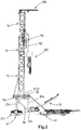
- Figure 1 shows a drilling rig 1 for drilling a wellbore and for other wellbore related activities, e.g. for plug and abandonment of non-productive wellbores, well intervention, etc.
- the rig 1 is a mobile rig composed of modules that are transportable by road vehicles from one drilling site to another.
- the invention may however also be of use in non-mobile rigs and/or non-modular rigs, e.g. rigs with a derrick structure over a moonpool on an offshore drilling vessel.
- the rig 1 comprises a drilling tower 10, which is embodied here as a mast.
- the tower 10 can be embodied as a derrick.
- the mast 10 has a U-shaped horizontal cross section with a left-hand mast wall 11a, a rear mast wall 11b, and a right-hand mast wall 11c, and with an open front side 12.
- the mast comprises left-hand and right-hand vertical front posts 13a, 13d, rear corner posts 13b, 13d.
- Each front post 13a, d is connected by bracings, here a combination of horizontal and diagonal bracings, to a respective rear corner post 13b, 13c to form the side walls 11a, 11c of the mast.
- the rear corner posts 13b, 13c are also connected by bracings.
- the mast 10 is composed of multiple sections, including a crown section 14 at the top of the mast, a floor section 15 at the lower, and one or more intermediate mast sections 16.
- the vertical posts 13a,b,c,d are provided with connector members to secure the mast sections one on top of the other.
- the floor section 15 is provided at its lower end with a pivot structure 15a defining a horizontal pivot axis allowing the mast 10, preferably assembled in horizontal state, to be erected.
- the rig 1 comprises a drill floor 20 with a well center 21.
- a slip device 22 is arranged at the well center 21, e.g. a mechanized and remotely controllable slip device with one or more mobile slip members.
- the slip device 22 is adapted to support a drill string or other tubular string that extends into the wellbore.
- a tubulars connection makeup and breaking device 25 is arranged near the well center 21, e.g. an iron roughneck machine and/or a mechanized power tong device.
- the drill floor 20 is arranged in a mobile manner on a base structure 30 of the rig so as to be movable between a collapsed or assembly position on the one hand and a raised or operative position relative to the base structure 30 on the other hand (as shown in the figures).
- the figure 1 illustrates that the base structure comprises a left-hand base member 31 and a right hand base member 32, each composed of two elongated parts 31a, 31b, 32a, 32b that are connected end-to-end.
- two legs 25a, 26a, b extend that are pivotally connected to both the drill floor and the base member 31, 32 to form a parallelogram. If desired more parallel legs can be provided between each base member and the drill floor.
- Each base member 31, 32 is further provided with a telescopic hydraulic cylinder 34, 35 that is connectable to the drill floor 20 for moving the drill floor 20 between the collapsed and raised position thereof.
- a motorized drive e.g. including a winch, may be provided for this purpose.
- Figure 1 illustrates the presence of a locking beam 36 to lock the drill floor in its raised position.
- the figures illustrate that the base structure, here the members 31, 32, are provided with displacement feet 41, 41 allowing the rig 1, in erected state, to be displaced over the drill site, e.g. from one wellbore to an adjacent wellbore.
- displacement feet 41, 41 allowing the rig 1, in erected state, to be displaced over the drill site, e.g. from one wellbore to an adjacent wellbore.
- An example thereof is explained in WO2013/09147 of the present applicant.
- the drill floor 20 in its raised position allows for the arrangement of a BOP and/or other wellbore related equipment underneath the drill floor.
- the mast, base structure, and/or drill floor of the drilling rig could also be embodied as described in for example WO2013/133698 or in WO2014/178712 of the present applicant.
- Figure 1 also depicts the presence of a tubulars handling device 50 adapted to move tubulars between a vertical position aligned with the firing line through the well center 21 and a horizontal pick-up position.
- the depicted device is embodied as described in WO2014/133389 of the present applicant.
- the tubulars handling device 50 can be designed as described in WO2006/038790 of the present applicant.
- Figure 1 also depicts the presence of a tubulars bin system 60, e.g. in an embodiment as disclosed in WO2013/109148 of the present applicant with bins 61, 62 for storage and transportation of drilling tubulars, e.g. drill pipe joints 3, as well as an arrangement of slide bars 64 that allow for motion of the tubulars between the bins 61, 62 and the tubulars handling device 50.
- a tubulars bin system 60 e.g. in an embodiment as disclosed in WO2013/109148 of the present applicant with bins 61, 62 for storage and transportation of drilling tubulars, e.g. drill pipe joints 3, as well as an arrangement of slide bars 64 that allow for motion of the tubulars between the bins 61, 62 and the tubulars handling device 50.
- the mast 10, here intermediate section 16 thereof, is provided with one or more fingerboard devices 71, 72 that are adapted to store drilling tubulars stands 4 assembled from multiple drilling tubulars 3, here three as the stands are so-called triples having a length of about 90 ft.
- a left-hand fingerboard device 71 is mounted to the left-hand side 11a of the mast and a right-hand side fingerboard device 72 is mounted to the right-hand side 11c of the mast.
- Each of these fingerboard devices 71, 72 has fingers defining slots that extend parallel to the respective side of the mast and are open at the front side of the fingerboard device 71, 72.
- the lower ends of the store tubulars stands 4 may be supported on a non-depicted lower end support member for the stands.
- the rig 1 further comprises a top drive system 100 and a vertical motion drive that is adapted to cause vertical motion of the top drive system 100 relative to the drilling tower 10 in order to perform drilling and tripping operations.
- the top drive system 100 comprises:
- each of the front vertical posts 13a, d of the mast 10 is provided with a corresponding vertical rail 17, 18 that is static in its vertical position, so non-mobile relative to the tower 10.
- the carriage 110 is provided with rail followers 111 (see figure 18 ), e.g. rollers and/or glide members, so that the carriage is only vertically mobile up and down relative to the mast, at least over the height of the stands 4 to be handled.
- rail followers 111 e.g. rollers and/or glide members
- the top drive unit 120 and the tripping operation elevator 150 are each mobile relative to the traveling carriage 110. Furthermore the top drive system is provided with one or more actuators 140 that are adapted to cause the relative motion of the top drive unit 120 and of the tripping operation elevator 150 so as to provide:
- the top drive unit 120 In the drilling mode the top drive unit 120 is in operative position with the rotary torque output member 126 being aligned with the firing line 23. At the same time the tripping operation elevator 150 is in a non-operative position remote from the firing line 23, here forward of the firing line 23.
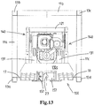
- the tripping operation elevator 150 In the tripping mode the tripping operation elevator 150 is in operative position aligned with the firing line 23 and at the same time the top drive unit 120 is in a non-operative position, here closer to the rear wall 11b of the C-cross section mast than in the operative drilling mode (e.g. compare figures 14 and 18 ).
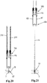
- the top drive system 100 is embodied such that - in the tripping mode - an unobstructed zone is present vertically above the tripping operation elevator 150 that allows the top drive system to be lowered along a drilling tubulars stand 4 in the firing line 23 above the drill floor 20, at least so that the top drive system is below the top end thereof, e.g. allowing lowering till near the drill floor. This will be explained in more detail later in conjunction with the fast tripping sequence depicted in figures 20 - 25 .
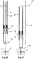
- the top drive system 100 is also embodied such that - in the tripping mode and with the top drive system lowered at least below the top end of said drilling tubulars stand (see e.g. figures 22, 23 , 24 ) -the drilling tubulars stand 4 is removable from the firing line 23, primarily in lateral direction, to place the drilling tubulars stand 4 in a fingerboard device 71, 72. This allows for a fast tripping process to be conducted.
- top drive system 100 here further comprises a drilling operation elevator 160, distinct from the tripping operation elevator 150,which elevator 160 is adapted to retain a drilling tubular or tubular stand 4 in vertical orientation below the rotary output member 126 of the top drive unit 120 in its operative position.
- a drilling operation elevator 160 distinct from the tripping operation elevator 150,which elevator 160 is adapted to retain a drilling tubular or tubular stand 4 in vertical orientation below the rotary output member 126 of the top drive unit 120 in its operative position.
- the top drive unit 120 comprises a top drive frame 121 that supports the top drive motor 125, a gear arrangement 122, and the rotary output member 126 that is supported by a bearing.
- the top drive unit here further comprises a grabber 127 and a mud saver valve 129 as is known in the art.
- the frame 121 is supported on the traveling carriage 110 by a parallelogram mechanism comprising at each of the left-hand side and the right-hand side of the carriage and the frame one pair of upper and lower support arms 131, 132. These arms 131, 132 are each pivotally connected to the carriage and the top drive unit to form four parallel and horizontal pivot axes 131a, 131b,132a, 132b.
- the actuators 140 e.g. hydraulic cylinders, are mounted between the traveling carriage 110 and the frame 121.
- one hydraulic cylinder 140 is mounted at the left-hand side and one at the right-hand side of the carriage 110 and the frame 121.
- suitable actuation of the actuators 140 causes the top drive unit 120 to be displaced relative to the carriage 110 between a position more inward in the mast 10 (closer to the rear wall 11b of the mast) and a more forward position wherein the rotary output member 126 is aligned with the firing line 23. As is preferred, even in said more forward position, a major portion of the top drive unit is still within the contour of the mast 10.
- the carriage comprises a structural frame with a left-hand carriage frame member 110a and a right-hand carriage frame member 110b interconnected by one or more transverse frame members 110c. These one or more transverse frame members extend rearward of the firing line 23 to provide the mentioned unobstructed zone allowing the lateral removal of the tubulars stand in forward direction.
- the firing line 23 is encompassed in a vertical plane P that extends between the front posts 13a, d of the mast 10, possibly between the guide rails 17, 18 so as to reduce any torsional loads.
- the tripping operation elevator 150 is suspended by right-hand side and left-hand side links 151 or bails that are each connected at an upper end thereof from a respective pivotal elevator support arm 153 that is pivotally connected to the carriage 110 about a horizontal pivot axis 131a.
- the elevator support arms 153 are each integrated with a respective support arm, here upper support arms 131 at the right-hand side and left-hand side of the carriage 110 so that each pair of an arm 153 and an arm 131 forms a one piece arms member that is pivotal about a horizontal axis 131a with the integrated arms 153 and 131 diverging.
- a pair of arms 131, 153 into a one piece integrated pivotal arms member is one manner to achieve that the top drive unit 120 and the tripping operation elevator 150 are mechanically linked so as to move in unison when operating the one or more actuators 140 in order to switch between the mentioned drilling mode and the mentioned tripping mode.
- the tripping elevator 150 in the top drive system 100 of the first aspect of the invention, even when not in use when in drilling mode, a fast and efficient switching can be made between the drilling mode and the tripping mode. There is no need to then install the tripping elevator 150 at the time of switching, which is advantageous in view of demands for crew members.
- one or more detent devices are provided to secure the top drive unit and/or the support for the tripping elevator relative to the traveling carriage 110 in the drilling mode and the tripping mode.
- one or more mobile detent members e.g. pins, are provided on the carriage that engage in a corresponding hole in one or more of the support arms.
- a linkage member may be provided to force each lower support arm 132 to move in the same direction as the upper support arm 131 when starting to move from a position, here corresponding to the drilling mode, wherein both said upper and lower support arms 131, 132 are vertical.
- the same effect may also be brought about by another means to force said corresponding motion of the support arms starting from the vertical position.
- a vertical position of both arms 131, 132 is advantageous in view of the vertical load path. It is, however, also possible that said arms 131, 132 are not completely vertical in said drilling mode.
- the tripping operation elevator may be arranged in an exchangeable manner.
- the winch 270 on the racking device can then be used for lifting and handling the rather heavy elevator 150.
- the elevator 150 has a body that is suited to all envisaged tubular diameters to be handled, e.g. just requiring the exchange or adjustment of one or more locking members for adaptation to a specific diameter.
- the top drive system further comprises a stabilizer rod 155 for each link 151 or bail from which the tripping operation elevator 150 is suspended.
- the stabilizer rods 155 each have one end that is pivotally connected to the link 151 and another end that is pivotally connected to the carriage 110 so as to form a parallelogram mechanism in combination with the pivotal elevator support arm 153.
- the stabilizer rods 155 are fixed length in this design.
- a hydraulic cylinder or other telescopic actuator can be provided as stabilizer rod between a link 151 and the carriage 110.
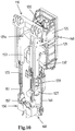
- the tripping operation elevator 150 comprises a C-shaped body in top view with a laterally open, e.g. to the front, vertical passage 156 through the elevator body that is dimensioned to allow unhindered passage of the elevator body along the drilling tubulars stand 4 in the firing line when the carriage 110 is lowered during tripping out, i.e. clearing any enlarged diameter portion(s) thereon formed by one or more connectors of the drilling tubulars stand.
- this elevator 150 comprises one or more mobile, here two pivotal, locking members 157, here on opposite sides of the vertical passage, which in a clearance position thereof (see left-hand locking member in figure 10 ) allow for passage of the enlarged diameter portion(s) during descent of the carriage 110 in tripping and in a locked position (see e.g. figure 8 ) engage underneath a shoulder formed by such an enlarged diameter portion, e.g. connector, e.g. threaded connector, of the tubular in order to allow the tubular, more in particular the tubulars string, to be lifted.
- a mobile here two pivotal, locking members 157, here on opposite sides of the vertical passage, which in a clearance position thereof (see left-hand locking member in figure 10 ) allow for passage of the enlarged diameter portion(s) during descent of the carriage 110 in tripping and in a locked position (see e.g. figure 8 ) engage underneath a shoulder formed by such an enlarged diameter portion, e.g. connector, e.g. threaded connector
- two locking members 157 may be provided on the tripping operation elevator 150, each pivotal about a horizontal axis, e.g. each having a tubular facing end with a semi-circular recess adapted to the diameter of the tubular to be handled.
- an actuator 158 may be provided for each locking member, e.g. allowing for remote control of the locking member.
- Figure 19 illustrates that the tripping elevator is provided with a C-shaped horizontal cross section funnel 159 at its lower end facilitating the sliding of the elevator along the tubulars stand 4 during descent of the carriage 110.
- drilling operation elevator 160 is equally suspended from links or bails 161 that are here pivotally suspended from the top drive unit 120.
- the drilling operation elevator 160 comprises an annular elevator body 162 that can be opened to allow introduction of a tubular in the elevator and then closed to form a closed annular body around the tubular, e.g. an actuator being provided for remote controlled opening and closing of the drilling elevator body.
- the closed annular elevator body may engage underneath a shoulder formed by an enlarged diameter portion of a tubular, e.g. a connector, e.g. a threaded connector at the end of the tubular.
- a motorized tilt mechanism 163 is provided to cause controlled tilting of the links 161 as is known in the art.
- the mast crowns section is provided with a crown block assembly 210 with a left-hand set 211 of sheaves and a right-hand set 212 of sheave, which sets are spaced apart from one another seen from the front of the mast so that an opening that is open at the front is present between the two sets, with the firing line 23 passing through this opening.
- the sheaves of the sets 211, 212 have horizontal axes generally parallel and in or close to the plane P, here at a small angle.
- An equalizing sheave 213 of the crown block is provided more rearward, at the rear of the mentioned opening between the sets 211, 212.
- the traveling carriage 110 is provided with a left-hand set 215 of sheaves and a right-hand set 216 of sheave with sheaves, which sets sheaves are spaced apart from one another seen from the front of the mast so that an opening that is open at the front is present between the two sets, with the firing line 23 passing through this opening.
- the set 215 is mounted at the top of frame member 110a and the set 216 at the top of frame member 110b.
- the sheaves on the travelling carriage 110 are also rotatable about a horizontal sheave axis.
- the rig 1 is provided with one or more, here two, drawwork winches 217, 218; one on each side of the base structure. Both winches 217, 218 here connect to a single drawwork cable 219 which cable passes over the mentioned sheaves in two multiple fall groups along the right-hand side and left-hand side of the mast, here along the inside of the respective front post 13a, d, so as to suspend the traveling carriage 110 from the crown block.
- one or more of the sheaves 215, 216 associated with the traveling carriage 110 may each be integrated in a respective detachable sheave block that is individually connectable and detachable, e.g. by remote control from an operator cabin, to the carriage 110 and which, when detached, may be locked (and unlocked), e.g. by remote control from an operator cabin, in an elevated position below the respective set of sheaves of the crown block.
- This allows to vary the active number of falls from which the carriage is suspended, e.g. allow for faster operation in situations wherein the load requirements are limited and allow for an increased number of active falls when high loads are to be handled.
- each fingerboard device 71 is mounted to the left-hand side 11a of the mast and a right-hand side fingerboard device 72 is mounted to the right-hand side 11c of the mast 10.
- each fingerboard device has fingers defining slots that extend parallel to the respective side of the mast and are open at the front side of the fingerboard device to allow for lateral introduction and removal of a tubulars stand from the fingerboard.
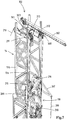
- the drilling rig comprises a tubulars racking device 250 comprising one or more mobile tubulars gripper assemblies adapted to grip a tubular or tubulars stand 4 and move the tubular or tubulars stand between the fingerboard device 71, 72 and the firing line 23.
- the tubulars racking device 250 comprises a structural frame supported by the mast 10, mainly at the front side thereof, at an elevated position thereon relative to the drill floor 20.
- the mast 10 is provided with one or more cantilevers 266, 267 at a height above the structural frame of the racking device 250, here said cantilevers 266 being secured to the front posts 13, d and extending in forward direction. Between each cantilever 266, 267 and the structural frame of the racking device one or more suspension cables or rods 268, 269 extend so as to provide additional vertical support for the structural frame.
- this structural frame comprises one or more horizontal rails 254, 255 extending across the front side of the mast 10 and across the front sides of the fingerboard devices 71, 72.
- the racking device 250 comprising a mobile tubulars gripper assembly 251 guided by said one or more rails 254, 255 and provided with one or more grippers 252, 253 and adapted to grip a tubular stand 4 and move the tubulars stand between the fingerboard devices 71, 72 and the firing line 23.
- the racking device is embodied to allow for passage of the top drive system 100 in its drilling mode and in its tripping mode.
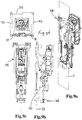
- the assembly 251 comprises a vertical carrier beam 256 which is supported by the one or more rails 254, 255 to allow travel in X-direction over said one or more rails 254, 255 and a vertical gripper beam 257 that is connected to the carrier beam 256 by parallelogram arms 258, 259 to allow travel of the grippers 252, 253 in Y-direction, here parallel to the slots in the fingerboards 71, 72.
- the gripper beam 257 carries the one or more grippers 252, 253, e.g. one gripper 252 at a fixed location and one being adjustable in vertical direction or both being adjustable in vertical direction relative to the gripper beam, e.g. in view of a controlled vertical stabbing motion by means of a vertical stabbing actuator 260 between the one or more grippers 252, 253 and the beam 257.
- the racking device 250 is also embodied to allow for vertical motion, in Z-direction, of the gripper beam 257.
- the vertical carrier beam 256 is provided with travellers 256a, 256b that vertically travel over the beam 256, which each traveller 256a, 256b having a hinge connected to a respective parallelogram arm 258, 259.
- a vertical motion actuator for the one or more travellers 256a, 256b is provided, here a vertically mounted hydraulic cylinder 256c between the lowermost traveller 256a and the carrier beam 256. This can be best seen in figure 5b , where the reference numeral is linked to the extended piston rod of the cylinder.
- the figures 5a , b also illustrate that the mobile tubulars gripper assembly 251 of the tubulars racking device is provided with an auxiliary winch 270 and a winch driven cable 271, here passing over a sheave 272 mounted on the gripper beam 257, e.g. at the lower end thereof.
- the sheave 272 and thus the cable 271 is also movable in these X and Y directions.
- the mobile tubulars gripper assembly 251 is positionable at least in a position such that the winch driven cable 272 is aligned above the well center 21, so in the firing line 23, and can be lowered to the well center 21 on the drill floor 20 to perform lifting operations above or near the well center using the auxiliary winch 270 on the tubulars racking device.
- a hook is present at the end of cable 271.
- the winch 270 can be used for lifting the slip device 22, e.g. when placed in a corresponding recess in the drill floor.
- Figure 7 illustrates that the tower, here the U-shaped horizontal cross section mast 10, is provided at the top thereof with an auxiliary crane 300 having a base 301 secured to the tower and a crane boom 302 connected via a vertical axis slew bearing 303 to the base 301 allowing to slew the boom, e.g. about a full revolution.
- the auxiliary crane 300 comprises a winch 305 and a winch driven cable 306 for hoisting of objects.
- the auxiliary crane is embodied such that the winch driven cable 306 can be passed vertically along the firing line 23 down to the well center 21 in the tripping mode of the top drive system 110 so as to allow for use of the auxiliary crane 300 for lifting operations at or near, or towards and away from, the well center 21.
- the auxiliary crane 300 is a jib or cantilever crane, wherein the boom 302 extends permanent in horizontal direction and wherein a trolley 308 is displaceable along the boom, with the trolley being provided with a sheave.
- the trolley 308 is at least positionable so that the winch driven cable 306 passing over the sheave is aligned with the firing line, and a position remote from said firing line position.
- the trolley could also support a winch with a winch driven cable.
- FIG 20 a situation is depicted wherein a drilling tubulars string 7 is suspended in the wellbore by means of the slip device 22. A top end portion of the string 7 sticks out above the slip device, which top end (as common) is provided with an enlarged diameter connector.
- the top drive system 100 is in the described tripping mode and the traveling carriage 110 has been lowered to an initial engagement level wherein the tripping operation elevator 150 is connected with the top end of the suspended string 7.
- the slip device 22 has released the string 7 and the carriage 110 has been lifted, so as to pull up a tubulars stand 4 above the well center 21 by means of the elevator 150.
- a double length stand 4 is pulled, but this could also be a triple stand 4.
- the slip device 22 is now operated to reengage on the string 7 so that the string 7, still including the connected stand 4, is vertically retained.
- the carriage 110 is lowered back towards the initial engagement level.
- the tripping operation elevator 150 slides down along the stand 4.
- the device 25 is operated to break up the connection between the stand 4 and the rest of the drill string, which includes advancing the device 25 from a parking position to a well center position as is shown in figures 22, 23 .
- the carriage has been lowered enough it becomes possible to engage one or more, e.g. both of the grippers of the racking device 250 (highly schematically shown in figure 24 ) with the stand 4, e.g. the grippers 251, 252 already encircling and/or gripping the stand 4 prior to the actual disconnection.
- the gripped stand 4 is then raised to complete the disconnection and allow for the racking device to move the stand laterally, e.g. in forward direction, out of the elevator 150 and to store the stand in a fingerboard 71, 72 as schematically depicted in figure 25 . This may involve actuation of locking members 157 to bring them in the clearance position.
- the descent of the carriage 110 is preferably done without pausing, and finally the elevator - with the stand 4 being removed from the firing line - reaches the top end of the suspended string 7 and engages therewith, e.g. by opening and then closing the locking members 157, so as to allow for the lifting of a next stand above the well center 21.
- the operations of the used devices may all be coordinated by one suitably programmed computerized controller, so that the entire tripping process or at least a significant part of the string tripping, may be done in automated manner, e.g. under supervision of one or more operators in an operator cabin, e.g. with a view on the front side of the mast.
- tripping out is done fast as at least one of the following steps is performed in time overlap with the lowering of the carriage 110:
- the grippers can be made to grip the stand 4 and the device 25 can be operated to disconnect the stand 4 by breaking the lower connection thereof.
- the racking device is operated to move the stand away from the firing line 23.
- the latter may involve remote control operation of the one or more locking devices 157 to allow the stand to be moved laterally out of the still descending elevator.
- the racking device250 can then continue to place the stand 4 in a fingerboard 71, 72 and the elevator 150 can be lowered over the top end of the next stand to be pulled out.
- the top drive unit 120 is operable in its normal manner, with the rotary output member aligned with the firing line 23 and with the elevator 150 moved into a non-operative position remote from the firing line.
- a central computerized control unit that is programmed to perform the tripping operation, at least of a major part of the drilling tubulars string 7, fully automated. It is envisaged that in such fully automated tripping sequence one or more operators in an operator cabin merely serve to supervise the process and respond in case of anomalies. In a semi-automated sequence some commands may be given via one or more input devices by the one or more operators, these commands starting parts of the sequence.
- drilling rig also allows for efficient and fast tripping in, which is basically done in reverse order of tripping out.
Landscapes
- Engineering & Computer Science (AREA)
- Life Sciences & Earth Sciences (AREA)
- Geology (AREA)
- Mining & Mineral Resources (AREA)
- Physics & Mathematics (AREA)
- Environmental & Geological Engineering (AREA)
- Fluid Mechanics (AREA)
- General Life Sciences & Earth Sciences (AREA)
- Geochemistry & Mineralogy (AREA)
- Mechanical Engineering (AREA)
- Earth Drilling (AREA)
Claims (6)
- Bohrmast (10) für eine Bohranlage (1) mit einem Bohrboden (20) mit einer Bohrlochmitte (21),
wobei der Bohrmast (10) einen U-förmigen horizontalen Querschnitt mit einer linken Mastwand (11a), einer hinteren Mastwand (11b) und einer rechten Mastwand (11c) und mit einer offenen Vorderseite (12) aufweist, wobei der Mast z.B. aus miteinander verbundenen Mastabschnitten zusammengesetzt ist, dadurch gekennzeichnet, dass
eine linke Fingerbühnenvorrichtung (71) an der linken Seite (11a) des Bohrmastes (10) angebracht ist und eine rechte Fingerbühnenvorrichtung (72) an der rechten Seite (11c) des Bohrmastes (10) angebracht ist,
wobei jede Fingerbühnenvorrichtung Finger aufweist, welche Schlitze definieren, welche sich parallel zu der jeweiligen Seite des Bohrmastes (10) erstrecken und an der Vorderseite der Fingerbühnenvorrichtung offen sind. - Bohrmast (10) nach Anspruch 1, wobei der Bohrmast (10) mit einer Rohrständer-Gestellvorrichtung (250) versehen ist, welche einen Strukturrahmen umfasst, welcher von dem Bohrmast (10) an einer erhöhten Position daran gehalten wird,
wobei der Strukturrahmen eine oder mehrere horizontale Schienen (254, 255) umfasst, welche sich über die Vorderseite des Bohrmastes (10) und über die Vorderseiten der Fingerbühnenvorrichtungen erstrecken,
wobei die Gestellvorrichtung ferner eine bewegliche Rohrgreiferanordnung (251) umfasst, welche von der einen oder den mehreren Schienen (254, 255) geführt wird und mit einem oder mehreren Greifern (252, 253) versehen ist und ausgestaltet ist, um einen Rohrständer (4) zu greifen und den Rohrständer zwischen den Fingerbühnenvorrichtungen (71, 72) und der Schusslinie zu bewegen. - Bohrmast (10) nach Anspruch 1, umfassend:ein oberes Antriebssystem (100), wobei der Bohrmast (10), z. B. die linke und die rechte Wand des Bohrmastes (10), mit einer oder mehreren vertikalen Schienen (17, 18) versehen ist, welche - bei Verwendung der Bohranlage - parallel zu einer vertikalen Schusslinie (23) verlaufen, welche sich durch die Bohrlochmitte erstreckt,wobei das obere Antriebssystem umfasst:- einen Fahrwagen (110), welcher entlang der vertikalen Schienen des Bohrmastes (10) mittels eines Vertikalbewegungsantriebs vertikal beweglich ist,- eine obere Antriebseinheit (120), welche von dem Wagen gehalten wird und einen oberen Antriebsmotor (125) und ein Drehmomentabgabeelement (125), z.B. einen Drehschaft, umfasst, welches ausgestaltet ist, um mit einem oberen Ende eines Bohrrohrstrangs in Eingriff gebracht zu werden, welcher sich in der Schusslinie (23) durch die Bohrlochmitte (21) erstreckt, um ein Moment auf den Bohrrohrstrang zu übertragen, um Bohrvorgänge auszuführen.
- Bohrmast (10) nach Anspruch 3, ferner umfassend eine Rohrständer-Gestellvorrichtung (250), wobei die Gestellvorrichtung einen Strukturrahmen umfasst, welcher von dem Bohrmast (10) in einer erhöhten Position daran relativ zu dem Bohrboden (20) gehalten wird,
wobei der Strukturrahmen eine oder mehrere horizontale Schienen (254, 255) aufweist, welche sich über die Vorderseite des Bohrmastes (10) und über die Vorderseiten der Fingerbühnenvorrichtungen erstrecken,
wobei die Gestellvorrichtung ferner eine bewegliche Rohrgreiferanordnung (251) umfasst, welche von der einen oder den mehreren Schienen (254, 255) geführt wird und mit einem oder mehreren Greifern (252, 253) versehen ist und ausgebildet ist, einen Rohrständer (4) zu greifen und den Rohrständer zwischen den Fingerbühnenvorrichtungen (71, 72) und der Schusslinie zu bewegen. - Bohrmast (10) nach Anspruch 4,
wobei der Bohrmast (10) mit einem oder mehreren Auslegern (266, 267) in einer Höhe über dem Strukturrahmen der Gestellvorrichtung (250) versehen ist, wobei sich ein oder mehrere Aufhängungskabel oder -stangen (268, 269) von dem einen oder den mehreren Auslegern zu dem Strukturrahmen erstrecken, um eine vertikale Halterung für den Strukturrahmen bereitzustellen. - Bohrmast (10) nach einem der Ansprüche 4-5,
wobei der Strukturrahmen der Gestellvorrichtung ein Dach aufweist.
Applications Claiming Priority (3)
| Application Number | Priority Date | Filing Date | Title |
|---|---|---|---|
| NL2014988A NL2014988B1 (en) | 2015-06-18 | 2015-06-18 | A drilling rig with a top drive sytem operable in a drilling mode and a tripping mode. |
| EP16742033.0A EP3310987B1 (de) | 2015-06-18 | 2016-06-09 | Bohrgestell mit einem in einem bohrmodus betreibbaren oberen antriebssystem und einem auslösemodus |
| PCT/NL2016/050415 WO2016204608A1 (en) | 2015-06-18 | 2016-06-09 | A drilling rig with a top drive system operable in a drilling mode and a tripping mode |
Related Parent Applications (2)
| Application Number | Title | Priority Date | Filing Date |
|---|---|---|---|
| EP16742033.0A Division-Into EP3310987B1 (de) | 2015-06-18 | 2016-06-09 | Bohrgestell mit einem in einem bohrmodus betreibbaren oberen antriebssystem und einem auslösemodus |
| EP16742033.0A Division EP3310987B1 (de) | 2015-06-18 | 2016-06-09 | Bohrgestell mit einem in einem bohrmodus betreibbaren oberen antriebssystem und einem auslösemodus |
Publications (3)
| Publication Number | Publication Date |
|---|---|
| EP3587728A2 EP3587728A2 (de) | 2020-01-01 |
| EP3587728A3 EP3587728A3 (de) | 2020-03-18 |
| EP3587728B1 true EP3587728B1 (de) | 2021-05-12 |
Family
ID=53783864
Family Applications (2)
| Application Number | Title | Priority Date | Filing Date |
|---|---|---|---|
| EP19189481.5A Active EP3587728B1 (de) | 2015-06-18 | 2016-06-09 | Bohrturm für eine bohranlage |
| EP16742033.0A Active EP3310987B1 (de) | 2015-06-18 | 2016-06-09 | Bohrgestell mit einem in einem bohrmodus betreibbaren oberen antriebssystem und einem auslösemodus |
Family Applications After (1)
| Application Number | Title | Priority Date | Filing Date |
|---|---|---|---|
| EP16742033.0A Active EP3310987B1 (de) | 2015-06-18 | 2016-06-09 | Bohrgestell mit einem in einem bohrmodus betreibbaren oberen antriebssystem und einem auslösemodus |
Country Status (8)
| Country | Link |
|---|---|
| US (2) | US11512532B2 (de) |
| EP (2) | EP3587728B1 (de) |
| CN (2) | CN107849903B (de) |
| AU (1) | AU2016281290B2 (de) |
| CA (1) | CA2989541C (de) |
| MX (1) | MX2017016595A (de) |
| NL (1) | NL2014988B1 (de) |
| WO (1) | WO2016204608A1 (de) |
Families Citing this family (46)
| Publication number | Priority date | Publication date | Assignee | Title |
|---|---|---|---|---|
| US9926719B2 (en) | 2013-02-13 | 2018-03-27 | Nabors Drilling Technologies Usa, Inc. | Slingshot side saddle substructure |
| AU2014204515B2 (en) * | 2014-07-18 | 2017-12-21 | Exploration Drill Masters Chile S.A. | Semiautomated drill rod handling apparatus and method, hand-held haul plug spinner and haul plug combination and drill rod handling system with both |
| EP3362635A1 (de) * | 2015-10-12 | 2018-08-22 | Itrec B.V. | Wartung einer oberen antriebsvorrichtung einer bohrlochbohranlage |
| WO2017087349A1 (en) * | 2015-11-16 | 2017-05-26 | Schlumberger Technology Corporation | Automated tubular racking system |
| US10697255B2 (en) | 2015-11-16 | 2020-06-30 | Schlumberger Technology Corporation | Tubular delivery arm for a drilling rig |
| US10519727B2 (en) | 2015-11-17 | 2019-12-31 | Schlumberger Technology Corporation | High trip rate drilling rig |
| US10844674B2 (en) | 2016-04-29 | 2020-11-24 | Schlumberger Technology Corporation | High trip rate drilling rig |
| MX2018013254A (es) * | 2016-04-29 | 2019-08-12 | Schlumberger Technology Bv | Equipo de perforacion con velocidad de maniobra alta. |
| WO2017190118A2 (en) | 2016-04-29 | 2017-11-02 | Schlumberger Technology Corporation | Tubular delivery arm for a drilling rig |
| WO2017214148A1 (en) | 2016-06-07 | 2017-12-14 | Nabors Drilling Technologies Usa, Inc. | Side saddle slingshot drilling rig |
| NL2018663B1 (en) * | 2017-04-06 | 2018-10-17 | Itrec Bv | A drilling rig with a top drive system operable in a wellbore drilling mode, tripping mode and bypassing mode |
| NL2019225B1 (en) * | 2017-07-11 | 2019-01-25 | Itrec Bv | Vessel and method to perform subsea wellbore related operations |
| EP3688232B1 (de) | 2017-09-28 | 2023-08-09 | Itrec B.V. | Verschliessen und auflassen eines oder mehrerer bohrlöcher einer offshore-plattform unter verwendung eines hubschiffs |
| US10597954B2 (en) | 2017-10-10 | 2020-03-24 | Schlumberger Technology Corporation | Sequencing for pipe handling |
| US10876363B2 (en) * | 2017-12-19 | 2020-12-29 | Caterpillar Global Mining Equipment Llc | Negative angle capable blasthole drilling mast |
| US11015402B2 (en) * | 2018-04-27 | 2021-05-25 | Canrig Robotic Technologies As | System and method for conducting subterranean operations |
| US10822891B2 (en) * | 2018-04-27 | 2020-11-03 | Canrig Robotic Technologies As | System and method for conducting subterranean operations |
| CN108691507B (zh) * | 2018-07-05 | 2023-12-08 | 上海兰石重工机械有限公司 | 一种钻机用顶部驱动钻井装置 |
| US10837238B2 (en) | 2018-07-19 | 2020-11-17 | Nabors Drilling Technologies Usa, Inc. | Side saddle slingshot continuous motion rig |
| US11613940B2 (en) | 2018-08-03 | 2023-03-28 | National Oilwell Varco, L.P. | Devices, systems, and methods for robotic pipe handling |
| CN109138897B (zh) * | 2018-09-26 | 2023-10-17 | 廊坊景隆重工机械有限公司 | 井口对中装置及具有其的修井装备 |
| CN111236864B (zh) * | 2018-11-29 | 2024-10-29 | 中国石油天然气集团有限公司 | 用于升降顶部驱动钻井装置的设备 |
| US11891864B2 (en) * | 2019-01-25 | 2024-02-06 | National Oilwell Varco, L.P. | Pipe handling arm |
| US11988059B2 (en) | 2019-02-22 | 2024-05-21 | National Oilwell Varco, L.P. | Dual activity top drive |
| DE102019206598A1 (de) * | 2019-05-08 | 2020-11-12 | Bentec Gmbh Drilling & Oilfield Systems | Landbohranlage und Verfahren zum Bewegen eines Topdrive in einem Bohrmast einer Landbohranlage |
| NO20221357A1 (en) * | 2020-07-06 | 2022-12-19 | Nabors Drilling Tech Usa Inc | Robotic pipe handler systems |
| CN111779474B (zh) * | 2020-08-07 | 2025-11-14 | 王海峰 | 一种钻井顶驱吊环倾斜角度检测装置及方法 |
| CN114476944A (zh) * | 2020-10-28 | 2022-05-13 | 濮阳市百福瑞德石油科技有限公司 | 一种防止顶驱吊环前倾碰撞猴台或后倾碰撞顶驱导轨的监控方法 |
| KR102498333B1 (ko) * | 2020-12-10 | 2023-02-10 | 동의대학교 산학협력단 | 해양 시추 장비들을 위한 충돌 방지 시스템용 시뮬레이터 구현을 위한 장치 및 방법 |
| CN116122752B (zh) * | 2021-11-15 | 2025-12-30 | 中油国家油气钻井装备工程技术研究中心有限公司 | 一种自动化钻杆排放装置 |
| CN116411832B (zh) * | 2021-12-30 | 2025-12-23 | 中油国家油气钻井装备工程技术研究中心有限公司 | 用于立根低位排放的管柱自动化处理方法 |
| CN114575907B (zh) * | 2022-03-15 | 2025-08-12 | 合肥工业大学 | 基于反馈调节的竖井排烟抑制吸穿装置及使用方法 |
| CN114671315B (zh) * | 2022-04-07 | 2023-09-26 | 南通润雅机电科技有限公司 | 一种带有紧急制动辅助的电梯安装用井架 |
| US20250305375A1 (en) * | 2022-05-11 | 2025-10-02 | Dennis VOLLMAR | Modular well tubular handling system and method of use |
| CN117188983A (zh) * | 2022-05-30 | 2023-12-08 | 中国石油天然气集团有限公司 | 一种连续运动钻机及其工作方法 |
| CN114922566B (zh) * | 2022-07-20 | 2022-10-04 | 山东济矿鲁能煤电股份有限公司阳城煤矿 | 一种用于煤矿开采的岩层钻进设备 |
| CN115303423B (zh) * | 2022-10-12 | 2022-12-27 | 启东豪通海洋工程有限公司 | 钻井平台的甲板吊基座加强结构 |
| CN115852929A (zh) * | 2023-03-02 | 2023-03-28 | 中交第四航务工程勘察设计院有限公司 | 井下式静力触探成套施工装置 |
| US12247446B2 (en) | 2023-03-06 | 2025-03-11 | Helmerich & Payne, Inc. | Method and apparatus for moving tubular rotary slips |
| CN116733424B (zh) * | 2023-08-15 | 2023-10-31 | 黑龙江百世永华流体设备有限公司 | 多功能一体化智能釆油集成设备 |
| CN120159306A (zh) * | 2023-12-15 | 2025-06-17 | 中国石油集团渤海石油装备制造有限公司 | 折叠石油钻机井架及井架拆卸方法 |
| CN117779822B (zh) * | 2024-02-23 | 2024-04-19 | 广州文船重工有限公司 | 一种组合式导管架制造组装支撑装置及其使用方法 |
| CN118208158B (zh) * | 2024-05-21 | 2024-08-20 | 英特莱福(青岛)海洋装备技术有限公司 | 一种海洋修井机智能排管平台及控制系统 |
| CN120251193B (zh) * | 2025-06-05 | 2025-08-05 | 山东胜利伟业石油工程技术服务有限公司 | 一种用于测井仪器的对接装置 |
| CN120844904B (zh) * | 2025-09-24 | 2025-11-28 | 东营鑫诺新能源科技有限公司 | 顶部驱动钻井装置 |
| CN121701098A (zh) * | 2026-02-12 | 2026-03-20 | 河北永明地质工程机械有限公司 | 一种钻井和下套管一体化设备 |
Family Cites Families (58)
| Publication number | Priority date | Publication date | Assignee | Title |
|---|---|---|---|---|
| US2168837A (en) * | 1937-12-20 | 1939-08-08 | Lantrip M York | Oil well rig |
| US2742260A (en) * | 1953-07-17 | 1956-04-17 | Patterson Luther | Well derrick |
| US4397605A (en) * | 1979-06-05 | 1983-08-09 | Cowgill Charles F | Mechanized stand handling apparatus for drilling rigs |
| US4462733A (en) * | 1982-04-23 | 1984-07-31 | Hughes Tool Company | Beam type racking system |
| US4709766A (en) * | 1985-04-26 | 1987-12-01 | Varco International, Inc. | Well pipe handling machine |
| US4696207A (en) * | 1985-04-26 | 1987-09-29 | Varco International, Inc. | Well pipe handling machine |
| DK517285D0 (da) * | 1985-11-08 | 1985-11-08 | Dansk Ind Syndikat | Fremgangsmaade og borerig til boring af borehuller |
| US4765401A (en) * | 1986-08-21 | 1988-08-23 | Varco International, Inc. | Apparatus for handling well pipe |
| SU1703805A1 (ru) * | 1987-08-17 | 1992-01-07 | Азербайджанский научно-исследовательский и проектно-конструкторский институт нефтяного машиностроения | Установка дл спуско-подъемных операций на скважинах |
| DK46388D0 (da) * | 1988-01-29 | 1988-01-29 | Dansk Ind Syndikat | Indretning til boretaarn |
| US6536520B1 (en) * | 2000-04-17 | 2003-03-25 | Weatherford/Lamb, Inc. | Top drive casing system |
| US6068066A (en) * | 1998-08-20 | 2000-05-30 | Byrt; Harry F. | Hydraulic drilling rig |
| US6926103B1 (en) * | 2001-07-02 | 2005-08-09 | Itrec B.V. | Splittable block on a derrick |
| US20030111232A1 (en) * | 2001-12-17 | 2003-06-19 | Welsh Walter Thomas | Crown block shifting apparatus and method |
| US6926259B1 (en) * | 2003-03-12 | 2005-08-09 | Itrec B.V. | Hoist system |
| US7377324B2 (en) * | 2003-11-10 | 2008-05-27 | Tesco Corporation | Pipe handling device, method and system |
| US7021402B2 (en) * | 2003-12-15 | 2006-04-04 | Itrec B.V. | Method for using a multipurpose unit with multipurpose tower and a surface blow out preventer |
| BRPI0515536A (pt) * | 2004-09-22 | 2008-07-29 | Nat Oilwell Lp | sistema de estaleiramento de tubo |
| WO2006038790A1 (en) | 2004-10-07 | 2006-04-13 | Itrec B.V. | Tubular handling apparatus and a drilling rig |
| US7794192B2 (en) * | 2004-11-29 | 2010-09-14 | Iron Derrickman Ltd. | Apparatus for handling and racking pipes |
| US7331746B2 (en) * | 2004-11-29 | 2008-02-19 | Iron Derrickman Ltd. | Apparatus for handling and racking pipes |
| US7967541B2 (en) * | 2004-11-29 | 2011-06-28 | Weatherford Canada Partnership | Apparatus for handling and racking pipes |
| US7350586B2 (en) * | 2005-05-06 | 2008-04-01 | Guidry Mark L | Casing running tool and method of using same |
| US7503394B2 (en) * | 2005-06-08 | 2009-03-17 | Frank's Casing & Rental Tools, Inc. | System for running oilfield tubulars into wellbores and method for using same |
| CA2551884C (en) * | 2005-07-19 | 2009-12-15 | National-Oilwell, L.P. | Single joint drilling system with inclined pipe handling system |
| US8408288B2 (en) * | 2006-03-07 | 2013-04-02 | Xtreme Drilling And Coil Services Corp. | System for conducting jointed pipe and coiled tubing operations |
| US20070251700A1 (en) * | 2006-04-28 | 2007-11-01 | Mason David B | Tubular running system |
| CA2572758C (en) * | 2007-01-04 | 2010-10-26 | Gerald Lesko | A guide rail system for a telescoping mast on a drilling rig |
| EP1953334B1 (de) * | 2007-01-08 | 2016-11-09 | National Oilwell Varco, L.P. | Rohrhandhabungssystem und Verfahren |
| CN102123906B (zh) * | 2008-02-15 | 2014-03-26 | 伊特雷科公司 | 海上钻探船 |
| EP2425090B1 (de) * | 2009-04-29 | 2013-06-19 | Itrec B.V. | Aufbewahrungs- und handhabungssystem für rohrförmige materialien |
| US8992152B2 (en) * | 2009-08-05 | 2015-03-31 | Itrec B.V. | Tubular handling system and method for handling tubulars |
| US8607898B2 (en) * | 2010-05-25 | 2013-12-17 | Rodgers Technology, Llc | Force compensator for top drive assembly |
| US8127836B1 (en) * | 2010-08-23 | 2012-03-06 | Larry G. Keast | Top drive with an airlift thread compensator and a hollow cylinder rod providing minimum flexing of conduit |
| CN101942976B (zh) * | 2010-09-01 | 2012-08-15 | 中国石油天然气集团公司 | 连续循环钻井系统的钻杆接头定位控制方法 |
| US8727039B1 (en) * | 2010-12-07 | 2014-05-20 | Larry G. Keast | Torque measuring top drive |
| US9080398B2 (en) * | 2010-12-23 | 2015-07-14 | Frank's International, Llc | Wellbore tubular running devices, systems and methods |
| US8893825B1 (en) * | 2011-01-25 | 2014-11-25 | Steve Akerman | Telescoping drilling derrick with guide track and top drive guide assembly |
| CN202108420U (zh) * | 2011-04-22 | 2012-01-11 | 中国石油天然气集团公司 | 陆地双联钻机井架 |
| KR101606253B1 (ko) | 2011-07-14 | 2016-03-24 | 엘지전자 주식회사 | 무선 통신 시스템에서 멤버십 확인 또는 접속 제어를 수행하는 방법 및 장치 |
| WO2013082172A1 (en) * | 2011-11-28 | 2013-06-06 | T&T Engineering Services, Inc. | Tubular stand building and racking system |
| US9243450B1 (en) * | 2012-01-17 | 2016-01-26 | Canyon Oak Energy LLC | System for operating a drilling rig with a retracting guide dolly and a top drive |
| NL2008134C2 (en) | 2012-01-18 | 2013-07-22 | Itrec Bv | Well drilling tubulars bin system, and method for use of system. |
| WO2013109147A2 (en) | 2012-01-20 | 2013-07-25 | Itrec B.V. | Displaceable drilling rig comprising a drilling tower |
| GB201201607D0 (en) * | 2012-01-31 | 2012-03-14 | Larkin Brendan | Drilling-pipe handling apparatus and method |
| US9169698B2 (en) | 2012-03-06 | 2015-10-27 | Itrec B.V. | Modular drilling rig system |
| US9115550B2 (en) * | 2012-04-14 | 2015-08-25 | Kasia L. Robnett | Robotic disassembly method at a well site |
| US9074421B2 (en) * | 2012-10-05 | 2015-07-07 | National Oilwell Varco, L.P. | Self-locking top drive guide system |
| BR112015021058A8 (pt) | 2013-03-01 | 2019-11-26 | Itrec Bv | sistemas e método para manipular materiais tubulares |
| US9951539B2 (en) | 2013-04-29 | 2018-04-24 | Itrec B.V. | Modular drilling rig system and method for assembling the same |
| SG11201508906PA (en) * | 2013-05-03 | 2015-11-27 | Itrec Bv | A top drive well drilling installation |
| US9932783B2 (en) * | 2014-08-27 | 2018-04-03 | Nabors Industries, Inc. | Laterally moving racker device on a drilling rig |
| GB2532267A (en) * | 2014-11-14 | 2016-05-18 | Nat Oilwell Varco Norway As | A method for placing and removing pipe from a finger rack |
| US10053934B2 (en) * | 2014-12-08 | 2018-08-21 | National Oilwell Varco, L.P. | Floor mounted racking arm for handling drill pipe |
| GB2537159A (en) * | 2015-04-10 | 2016-10-12 | Nat Oilwell Varco Uk Ltd | A tool and method for facilitating communication between a computer apparatus and a device in a drill string |
| US10519727B2 (en) * | 2015-11-17 | 2019-12-31 | Schlumberger Technology Corporation | High trip rate drilling rig |
| CN106522832B (zh) * | 2016-12-16 | 2019-05-24 | 四川宏华石油设备有限公司 | 垂直起升钻机 |
| US10597954B2 (en) * | 2017-10-10 | 2020-03-24 | Schlumberger Technology Corporation | Sequencing for pipe handling |
-
2015
- 2015-06-18 NL NL2014988A patent/NL2014988B1/en not_active IP Right Cessation
-
2016
- 2016-06-09 EP EP19189481.5A patent/EP3587728B1/de active Active
- 2016-06-09 AU AU2016281290A patent/AU2016281290B2/en active Active
- 2016-06-09 WO PCT/NL2016/050415 patent/WO2016204608A1/en not_active Ceased
- 2016-06-09 CN CN201680044613.2A patent/CN107849903B/zh active Active
- 2016-06-09 US US15/737,068 patent/US11512532B2/en active Active
- 2016-06-09 MX MX2017016595A patent/MX2017016595A/es unknown
- 2016-06-09 EP EP16742033.0A patent/EP3310987B1/de active Active
- 2016-06-09 CA CA2989541A patent/CA2989541C/en active Active
- 2016-06-09 CN CN202010098980.9A patent/CN111287677B/zh active Active
-
2022
- 2022-11-02 US US17/979,223 patent/US12065892B2/en active Active
Non-Patent Citations (1)
| Title |
|---|
| None * |
Also Published As
| Publication number | Publication date |
|---|---|
| AU2016281290B2 (en) | 2020-09-17 |
| EP3310987A1 (de) | 2018-04-25 |
| MX2017016595A (es) | 2018-05-28 |
| CN111287677A (zh) | 2020-06-16 |
| EP3310987B1 (de) | 2019-09-25 |
| EP3587728A2 (de) | 2020-01-01 |
| CA2989541C (en) | 2023-10-03 |
| US20230048765A1 (en) | 2023-02-16 |
| NL2014988B1 (en) | 2017-01-23 |
| WO2016204608A1 (en) | 2016-12-22 |
| US20180216405A1 (en) | 2018-08-02 |
| AU2016281290A1 (en) | 2018-02-01 |
| CN107849903A (zh) | 2018-03-27 |
| CN107849903B (zh) | 2020-03-06 |
| US12065892B2 (en) | 2024-08-20 |
| EP3587728A3 (de) | 2020-03-18 |
| CN111287677B (zh) | 2021-11-05 |
| CA2989541A1 (en) | 2016-12-22 |
| US11512532B2 (en) | 2022-11-29 |
Similar Documents
| Publication | Publication Date | Title |
|---|---|---|
| US12065892B2 (en) | Drilling rig with a top drive system operable in a drilling mode and a tripping mode | |
| EP3607167B1 (de) | Bohranlage mit kraftdrehkopf, welcher in bohrmodus, trippingmodus, bypassmodus eingesetzt werden kann | |
| RU2435929C2 (ru) | Способ и устройство для проведения операций в подземных буровых скважинах | |
| US11053753B2 (en) | Offshore subsea wellbore activities system and method | |
| CA2798377C (en) | Apparatus and method for positioning connection equipment on a drilling rig | |
| US6412576B1 (en) | Methods and apparatus for subterranean drilling utilizing a top drive | |
| EP3472422B1 (de) | Bohrlochbohrung mit drehbarer kopfklemmenkomponente | |
| CA2645232C (en) | A tubular handling system for drilling rigs | |
| US20180298693A1 (en) | A top drive well drilling installation | |
| EA013622B1 (ru) | Интегрированные верхний привод и устьевое подающее устройство гибкой насосно-компрессорной трубы | |
| BR102017027733A2 (pt) | Equipamento de perfuração, e, método para manobrar uma coluna tubular de perfuração |
Legal Events
| Date | Code | Title | Description |
|---|---|---|---|
| PUAI | Public reference made under article 153(3) epc to a published international application that has entered the european phase |
Free format text: ORIGINAL CODE: 0009012 |
|
| STAA | Information on the status of an ep patent application or granted ep patent |
Free format text: STATUS: THE APPLICATION HAS BEEN PUBLISHED |
|
| AC | Divisional application: reference to earlier application |
Ref document number: 3310987 Country of ref document: EP Kind code of ref document: P |
|
| AK | Designated contracting states |
Kind code of ref document: A2 Designated state(s): AL AT BE BG CH CY CZ DE DK EE ES FI FR GB GR HR HU IE IS IT LI LT LU LV MC MK MT NL NO PL PT RO RS SE SI SK SM TR |
|
| PUAL | Search report despatched |
Free format text: ORIGINAL CODE: 0009013 |
|
| AK | Designated contracting states |
Kind code of ref document: A3 Designated state(s): AL AT BE BG CH CY CZ DE DK EE ES FI FR GB GR HR HU IE IS IT LI LT LU LV MC MK MT NL NO PL PT RO RS SE SI SK SM TR |
|
| RIC1 | Information provided on ipc code assigned before grant |
Ipc: E21B 3/02 20060101AFI20200207BHEP Ipc: E21B 19/00 20060101ALI20200207BHEP Ipc: E21B 15/00 20060101ALI20200207BHEP Ipc: E21B 19/06 20060101ALI20200207BHEP |
|
| STAA | Information on the status of an ep patent application or granted ep patent |
Free format text: STATUS: REQUEST FOR EXAMINATION WAS MADE |
|
| 17P | Request for examination filed |
Effective date: 20200911 |
|
| RBV | Designated contracting states (corrected) |
Designated state(s): AL AT BE BG CH CY CZ DE DK EE ES FI FR GB GR HR HU IE IS IT LI LT LU LV MC MK MT NL NO PL PT RO RS SE SI SK SM TR |
|
| GRAP | Despatch of communication of intention to grant a patent |
Free format text: ORIGINAL CODE: EPIDOSNIGR1 |
|
| STAA | Information on the status of an ep patent application or granted ep patent |
Free format text: STATUS: GRANT OF PATENT IS INTENDED |
|
| INTG | Intention to grant announced |
Effective date: 20201204 |
|
| GRAS | Grant fee paid |
Free format text: ORIGINAL CODE: EPIDOSNIGR3 |
|
| GRAA | (expected) grant |
Free format text: ORIGINAL CODE: 0009210 |
|
| STAA | Information on the status of an ep patent application or granted ep patent |
Free format text: STATUS: THE PATENT HAS BEEN GRANTED |
|
| AC | Divisional application: reference to earlier application |
Ref document number: 3310987 Country of ref document: EP Kind code of ref document: P |
|
| AK | Designated contracting states |
Kind code of ref document: B1 Designated state(s): AL AT BE BG CH CY CZ DE DK EE ES FI FR GB GR HR HU IE IS IT LI LT LU LV MC MK MT NL NO PL PT RO RS SE SI SK SM TR |
|
| REG | Reference to a national code |
Ref country code: GB Ref legal event code: FG4D |
|
| REG | Reference to a national code |
Ref country code: CH Ref legal event code: EP |
|
| REG | Reference to a national code |
Ref country code: DE Ref legal event code: R096 Ref document number: 602016057931 Country of ref document: DE |
|
| REG | Reference to a national code |
Ref country code: IE Ref legal event code: FG4D |
|
| REG | Reference to a national code |
Ref country code: AT Ref legal event code: REF Ref document number: 1392278 Country of ref document: AT Kind code of ref document: T Effective date: 20210615 |
|
| REG | Reference to a national code |
Ref country code: NL Ref legal event code: FP |
|
| REG | Reference to a national code |
Ref country code: LT Ref legal event code: MG9D |
|
| REG | Reference to a national code |
Ref country code: AT Ref legal event code: MK05 Ref document number: 1392278 Country of ref document: AT Kind code of ref document: T Effective date: 20210512 |
|
| PG25 | Lapsed in a contracting state [announced via postgrant information from national office to epo] |
Ref country code: LT Free format text: LAPSE BECAUSE OF FAILURE TO SUBMIT A TRANSLATION OF THE DESCRIPTION OR TO PAY THE FEE WITHIN THE PRESCRIBED TIME-LIMIT Effective date: 20210512 Ref country code: HR Free format text: LAPSE BECAUSE OF FAILURE TO SUBMIT A TRANSLATION OF THE DESCRIPTION OR TO PAY THE FEE WITHIN THE PRESCRIBED TIME-LIMIT Effective date: 20210512 Ref country code: FI Free format text: LAPSE BECAUSE OF FAILURE TO SUBMIT A TRANSLATION OF THE DESCRIPTION OR TO PAY THE FEE WITHIN THE PRESCRIBED TIME-LIMIT Effective date: 20210512 Ref country code: AT Free format text: LAPSE BECAUSE OF FAILURE TO SUBMIT A TRANSLATION OF THE DESCRIPTION OR TO PAY THE FEE WITHIN THE PRESCRIBED TIME-LIMIT Effective date: 20210512 Ref country code: BG Free format text: LAPSE BECAUSE OF FAILURE TO SUBMIT A TRANSLATION OF THE DESCRIPTION OR TO PAY THE FEE WITHIN THE PRESCRIBED TIME-LIMIT Effective date: 20210812 |
|
| PG25 | Lapsed in a contracting state [announced via postgrant information from national office to epo] |
Ref country code: PL Free format text: LAPSE BECAUSE OF FAILURE TO SUBMIT A TRANSLATION OF THE DESCRIPTION OR TO PAY THE FEE WITHIN THE PRESCRIBED TIME-LIMIT Effective date: 20210512 Ref country code: NO Free format text: LAPSE BECAUSE OF FAILURE TO SUBMIT A TRANSLATION OF THE DESCRIPTION OR TO PAY THE FEE WITHIN THE PRESCRIBED TIME-LIMIT Effective date: 20210812 Ref country code: LV Free format text: LAPSE BECAUSE OF FAILURE TO SUBMIT A TRANSLATION OF THE DESCRIPTION OR TO PAY THE FEE WITHIN THE PRESCRIBED TIME-LIMIT Effective date: 20210512 Ref country code: PT Free format text: LAPSE BECAUSE OF FAILURE TO SUBMIT A TRANSLATION OF THE DESCRIPTION OR TO PAY THE FEE WITHIN THE PRESCRIBED TIME-LIMIT Effective date: 20210913 Ref country code: SE Free format text: LAPSE BECAUSE OF FAILURE TO SUBMIT A TRANSLATION OF THE DESCRIPTION OR TO PAY THE FEE WITHIN THE PRESCRIBED TIME-LIMIT Effective date: 20210512 Ref country code: RS Free format text: LAPSE BECAUSE OF FAILURE TO SUBMIT A TRANSLATION OF THE DESCRIPTION OR TO PAY THE FEE WITHIN THE PRESCRIBED TIME-LIMIT Effective date: 20210512 Ref country code: GR Free format text: LAPSE BECAUSE OF FAILURE TO SUBMIT A TRANSLATION OF THE DESCRIPTION OR TO PAY THE FEE WITHIN THE PRESCRIBED TIME-LIMIT Effective date: 20210813 Ref country code: IS Free format text: LAPSE BECAUSE OF FAILURE TO SUBMIT A TRANSLATION OF THE DESCRIPTION OR TO PAY THE FEE WITHIN THE PRESCRIBED TIME-LIMIT Effective date: 20210912 |
|
| PG25 | Lapsed in a contracting state [announced via postgrant information from national office to epo] |
Ref country code: RO Free format text: LAPSE BECAUSE OF FAILURE TO SUBMIT A TRANSLATION OF THE DESCRIPTION OR TO PAY THE FEE WITHIN THE PRESCRIBED TIME-LIMIT Effective date: 20210512 Ref country code: SM Free format text: LAPSE BECAUSE OF FAILURE TO SUBMIT A TRANSLATION OF THE DESCRIPTION OR TO PAY THE FEE WITHIN THE PRESCRIBED TIME-LIMIT Effective date: 20210512 Ref country code: CZ Free format text: LAPSE BECAUSE OF FAILURE TO SUBMIT A TRANSLATION OF THE DESCRIPTION OR TO PAY THE FEE WITHIN THE PRESCRIBED TIME-LIMIT Effective date: 20210512 Ref country code: DK Free format text: LAPSE BECAUSE OF FAILURE TO SUBMIT A TRANSLATION OF THE DESCRIPTION OR TO PAY THE FEE WITHIN THE PRESCRIBED TIME-LIMIT Effective date: 20210512 Ref country code: SK Free format text: LAPSE BECAUSE OF FAILURE TO SUBMIT A TRANSLATION OF THE DESCRIPTION OR TO PAY THE FEE WITHIN THE PRESCRIBED TIME-LIMIT Effective date: 20210512 Ref country code: ES Free format text: LAPSE BECAUSE OF FAILURE TO SUBMIT A TRANSLATION OF THE DESCRIPTION OR TO PAY THE FEE WITHIN THE PRESCRIBED TIME-LIMIT Effective date: 20210512 Ref country code: EE Free format text: LAPSE BECAUSE OF FAILURE TO SUBMIT A TRANSLATION OF THE DESCRIPTION OR TO PAY THE FEE WITHIN THE PRESCRIBED TIME-LIMIT Effective date: 20210512 |
|
| REG | Reference to a national code |
Ref country code: CH Ref legal event code: PL |
|
| REG | Reference to a national code |
Ref country code: DE Ref legal event code: R097 Ref document number: 602016057931 Country of ref document: DE |
|
| REG | Reference to a national code |
Ref country code: BE Ref legal event code: MM Effective date: 20210630 |
|
| PLBE | No opposition filed within time limit |
Free format text: ORIGINAL CODE: 0009261 |
|
| STAA | Information on the status of an ep patent application or granted ep patent |
Free format text: STATUS: NO OPPOSITION FILED WITHIN TIME LIMIT |
|
| PG25 | Lapsed in a contracting state [announced via postgrant information from national office to epo] |
Ref country code: MC Free format text: LAPSE BECAUSE OF FAILURE TO SUBMIT A TRANSLATION OF THE DESCRIPTION OR TO PAY THE FEE WITHIN THE PRESCRIBED TIME-LIMIT Effective date: 20210512 Ref country code: LU Free format text: LAPSE BECAUSE OF NON-PAYMENT OF DUE FEES Effective date: 20210609 |
|
| 26N | No opposition filed |
Effective date: 20220215 |
|
| GBPC | Gb: european patent ceased through non-payment of renewal fee |
Effective date: 20210812 |
|
| PG25 | Lapsed in a contracting state [announced via postgrant information from national office to epo] |
Ref country code: LI Free format text: LAPSE BECAUSE OF NON-PAYMENT OF DUE FEES Effective date: 20210630 Ref country code: IE Free format text: LAPSE BECAUSE OF NON-PAYMENT OF DUE FEES Effective date: 20210609 Ref country code: CH Free format text: LAPSE BECAUSE OF NON-PAYMENT OF DUE FEES Effective date: 20210630 |
|
| PG25 | Lapsed in a contracting state [announced via postgrant information from national office to epo] |
Ref country code: IS Free format text: LAPSE BECAUSE OF FAILURE TO SUBMIT A TRANSLATION OF THE DESCRIPTION OR TO PAY THE FEE WITHIN THE PRESCRIBED TIME-LIMIT Effective date: 20210912 Ref country code: FR Free format text: LAPSE BECAUSE OF NON-PAYMENT OF DUE FEES Effective date: 20210712 Ref country code: AL Free format text: LAPSE BECAUSE OF FAILURE TO SUBMIT A TRANSLATION OF THE DESCRIPTION OR TO PAY THE FEE WITHIN THE PRESCRIBED TIME-LIMIT Effective date: 20210512 |
|
| PG25 | Lapsed in a contracting state [announced via postgrant information from national office to epo] |
Ref country code: GB Free format text: LAPSE BECAUSE OF NON-PAYMENT OF DUE FEES Effective date: 20210812 Ref country code: BE Free format text: LAPSE BECAUSE OF NON-PAYMENT OF DUE FEES Effective date: 20210630 |
|
| P01 | Opt-out of the competence of the unified patent court (upc) registered |
Effective date: 20230522 |
|
| PG25 | Lapsed in a contracting state [announced via postgrant information from national office to epo] |
Ref country code: CY Free format text: LAPSE BECAUSE OF FAILURE TO SUBMIT A TRANSLATION OF THE DESCRIPTION OR TO PAY THE FEE WITHIN THE PRESCRIBED TIME-LIMIT Effective date: 20210512 |
|
| PG25 | Lapsed in a contracting state [announced via postgrant information from national office to epo] |
Ref country code: HU Free format text: LAPSE BECAUSE OF FAILURE TO SUBMIT A TRANSLATION OF THE DESCRIPTION OR TO PAY THE FEE WITHIN THE PRESCRIBED TIME-LIMIT; INVALID AB INITIO Effective date: 20160609 |
|
| PG25 | Lapsed in a contracting state [announced via postgrant information from national office to epo] |
Ref country code: MK Free format text: LAPSE BECAUSE OF FAILURE TO SUBMIT A TRANSLATION OF THE DESCRIPTION OR TO PAY THE FEE WITHIN THE PRESCRIBED TIME-LIMIT Effective date: 20210512 |
|
| PG25 | Lapsed in a contracting state [announced via postgrant information from national office to epo] |
Ref country code: TR Free format text: LAPSE BECAUSE OF FAILURE TO SUBMIT A TRANSLATION OF THE DESCRIPTION OR TO PAY THE FEE WITHIN THE PRESCRIBED TIME-LIMIT Effective date: 20210512 |
|
| PG25 | Lapsed in a contracting state [announced via postgrant information from national office to epo] |
Ref country code: MT Free format text: LAPSE BECAUSE OF FAILURE TO SUBMIT A TRANSLATION OF THE DESCRIPTION OR TO PAY THE FEE WITHIN THE PRESCRIBED TIME-LIMIT Effective date: 20210512 |
|
| PGFP | Annual fee paid to national office [announced via postgrant information from national office to epo] |
Ref country code: DE Payment date: 20250618 Year of fee payment: 10 |
|
| PGFP | Annual fee paid to national office [announced via postgrant information from national office to epo] |
Ref country code: NL Payment date: 20250624 Year of fee payment: 10 |
|
| PGFP | Annual fee paid to national office [announced via postgrant information from national office to epo] |
Ref country code: IT Payment date: 20250630 Year of fee payment: 10 |