EP3587678A1 - Water supply management system and method and computer-readable recording medium including instructon for performing the method - Google Patents
Water supply management system and method and computer-readable recording medium including instructon for performing the method Download PDFInfo
- Publication number
- EP3587678A1 EP3587678A1 EP19181343.5A EP19181343A EP3587678A1 EP 3587678 A1 EP3587678 A1 EP 3587678A1 EP 19181343 A EP19181343 A EP 19181343A EP 3587678 A1 EP3587678 A1 EP 3587678A1
- Authority
- EP
- European Patent Office
- Prior art keywords
- water
- stored
- controller
- storage tank
- inflow
- Prior art date
- Legal status (The legal status is an assumption and is not a legal conclusion. Google has not performed a legal analysis and makes no representation as to the accuracy of the status listed.)
- Granted
Links
Images




Classifications
-
- C—CHEMISTRY; METALLURGY
- C02—TREATMENT OF WATER, WASTE WATER, SEWAGE, OR SLUDGE
- C02F—TREATMENT OF WATER, WASTE WATER, SEWAGE, OR SLUDGE
- C02F1/00—Treatment of water, waste water, or sewage
- C02F1/006—Water distributors either inside a treatment tank or directing the water to several treatment tanks; Water treatment plants incorporating these distributors, with or without chemical or biological tanks
-
- G—PHYSICS
- G06—COMPUTING OR CALCULATING; COUNTING
- G06Q—INFORMATION AND COMMUNICATION TECHNOLOGY [ICT] SPECIALLY ADAPTED FOR ADMINISTRATIVE, COMMERCIAL, FINANCIAL, MANAGERIAL OR SUPERVISORY PURPOSES; SYSTEMS OR METHODS SPECIALLY ADAPTED FOR ADMINISTRATIVE, COMMERCIAL, FINANCIAL, MANAGERIAL OR SUPERVISORY PURPOSES, NOT OTHERWISE PROVIDED FOR
- G06Q50/00—Information and communication technology [ICT] specially adapted for implementation of business processes of specific business sectors, e.g. utilities or tourism
- G06Q50/06—Energy or water supply
-
- C—CHEMISTRY; METALLURGY
- C02—TREATMENT OF WATER, WASTE WATER, SEWAGE, OR SLUDGE
- C02F—TREATMENT OF WATER, WASTE WATER, SEWAGE, OR SLUDGE
- C02F1/00—Treatment of water, waste water, or sewage
- C02F1/008—Control or steering systems not provided for elsewhere in subclass C02F
-
- C—CHEMISTRY; METALLURGY
- C02—TREATMENT OF WATER, WASTE WATER, SEWAGE, OR SLUDGE
- C02F—TREATMENT OF WATER, WASTE WATER, SEWAGE, OR SLUDGE
- C02F9/00—Multistage treatment of water, waste water or sewage
-
- E—FIXED CONSTRUCTIONS
- E03—WATER SUPPLY; SEWERAGE
- E03B—INSTALLATIONS OR METHODS FOR OBTAINING, COLLECTING, OR DISTRIBUTING WATER
- E03B1/00—Methods or layout of installations for water supply
- E03B1/02—Methods or layout of installations for water supply for public or like main supply for industrial use
-
- E—FIXED CONSTRUCTIONS
- E03—WATER SUPPLY; SEWERAGE
- E03B—INSTALLATIONS OR METHODS FOR OBTAINING, COLLECTING, OR DISTRIBUTING WATER
- E03B1/00—Methods or layout of installations for water supply
- E03B1/04—Methods or layout of installations for water supply for domestic or like local supply
- E03B1/041—Greywater supply systems
-
- E—FIXED CONSTRUCTIONS
- E03—WATER SUPPLY; SEWERAGE
- E03B—INSTALLATIONS OR METHODS FOR OBTAINING, COLLECTING, OR DISTRIBUTING WATER
- E03B11/00—Arrangements or adaptations of tanks for water supply
- E03B11/10—Arrangements or adaptations of tanks for water supply for public or like main water supply
-
- E—FIXED CONSTRUCTIONS
- E03—WATER SUPPLY; SEWERAGE
- E03B—INSTALLATIONS OR METHODS FOR OBTAINING, COLLECTING, OR DISTRIBUTING WATER
- E03B11/00—Arrangements or adaptations of tanks for water supply
- E03B11/10—Arrangements or adaptations of tanks for water supply for public or like main water supply
- E03B11/14—Arrangements or adaptations of tanks for water supply for public or like main water supply of underground tanks
-
- E—FIXED CONSTRUCTIONS
- E03—WATER SUPPLY; SEWERAGE
- E03B—INSTALLATIONS OR METHODS FOR OBTAINING, COLLECTING, OR DISTRIBUTING WATER
- E03B3/00—Methods or installations for obtaining or collecting drinking water or tap water
-
- E—FIXED CONSTRUCTIONS
- E03—WATER SUPPLY; SEWERAGE
- E03B—INSTALLATIONS OR METHODS FOR OBTAINING, COLLECTING, OR DISTRIBUTING WATER
- E03B3/00—Methods or installations for obtaining or collecting drinking water or tap water
- E03B3/02—Methods or installations for obtaining or collecting drinking water or tap water from rain-water
-
- E—FIXED CONSTRUCTIONS
- E03—WATER SUPPLY; SEWERAGE
- E03B—INSTALLATIONS OR METHODS FOR OBTAINING, COLLECTING, OR DISTRIBUTING WATER
- E03B3/00—Methods or installations for obtaining or collecting drinking water or tap water
- E03B3/06—Methods or installations for obtaining or collecting drinking water or tap water from underground
- E03B3/08—Obtaining and confining water by means of wells
- E03B3/10—Obtaining and confining water by means of wells by means of pit wells
- E03B3/11—Obtaining and confining water by means of wells by means of pit wells in combination with tubes, e.g. perforated, extending horizontally, or upwardly inclined, exterior to the pits
-
- G—PHYSICS
- G06—COMPUTING OR CALCULATING; COUNTING
- G06Q—INFORMATION AND COMMUNICATION TECHNOLOGY [ICT] SPECIALLY ADAPTED FOR ADMINISTRATIVE, COMMERCIAL, FINANCIAL, MANAGERIAL OR SUPERVISORY PURPOSES; SYSTEMS OR METHODS SPECIALLY ADAPTED FOR ADMINISTRATIVE, COMMERCIAL, FINANCIAL, MANAGERIAL OR SUPERVISORY PURPOSES, NOT OTHERWISE PROVIDED FOR
- G06Q50/00—Information and communication technology [ICT] specially adapted for implementation of business processes of specific business sectors, e.g. utilities or tourism
- G06Q50/10—Services
- G06Q50/26—Government or public services
-
- C—CHEMISTRY; METALLURGY
- C02—TREATMENT OF WATER, WASTE WATER, SEWAGE, OR SLUDGE
- C02F—TREATMENT OF WATER, WASTE WATER, SEWAGE, OR SLUDGE
- C02F1/00—Treatment of water, waste water, or sewage
- C02F1/001—Processes for the treatment of water whereby the filtration technique is of importance
-
- C—CHEMISTRY; METALLURGY
- C02—TREATMENT OF WATER, WASTE WATER, SEWAGE, OR SLUDGE
- C02F—TREATMENT OF WATER, WASTE WATER, SEWAGE, OR SLUDGE
- C02F1/00—Treatment of water, waste water, or sewage
- C02F1/28—Treatment of water, waste water, or sewage by sorption
- C02F1/283—Treatment of water, waste water, or sewage by sorption using coal, charred products, or inorganic mixtures containing them
-
- C—CHEMISTRY; METALLURGY
- C02—TREATMENT OF WATER, WASTE WATER, SEWAGE, OR SLUDGE
- C02F—TREATMENT OF WATER, WASTE WATER, SEWAGE, OR SLUDGE
- C02F1/00—Treatment of water, waste water, or sewage
- C02F1/44—Treatment of water, waste water, or sewage by dialysis, osmosis or reverse osmosis
- C02F1/441—Treatment of water, waste water, or sewage by dialysis, osmosis or reverse osmosis by reverse osmosis
-
- C—CHEMISTRY; METALLURGY
- C02—TREATMENT OF WATER, WASTE WATER, SEWAGE, OR SLUDGE
- C02F—TREATMENT OF WATER, WASTE WATER, SEWAGE, OR SLUDGE
- C02F1/00—Treatment of water, waste water, or sewage
- C02F1/44—Treatment of water, waste water, or sewage by dialysis, osmosis or reverse osmosis
- C02F1/442—Treatment of water, waste water, or sewage by dialysis, osmosis or reverse osmosis by nanofiltration
-
- C—CHEMISTRY; METALLURGY
- C02—TREATMENT OF WATER, WASTE WATER, SEWAGE, OR SLUDGE
- C02F—TREATMENT OF WATER, WASTE WATER, SEWAGE, OR SLUDGE
- C02F1/00—Treatment of water, waste water, or sewage
- C02F1/44—Treatment of water, waste water, or sewage by dialysis, osmosis or reverse osmosis
- C02F1/444—Treatment of water, waste water, or sewage by dialysis, osmosis or reverse osmosis by ultrafiltration or microfiltration
-
- C—CHEMISTRY; METALLURGY
- C02—TREATMENT OF WATER, WASTE WATER, SEWAGE, OR SLUDGE
- C02F—TREATMENT OF WATER, WASTE WATER, SEWAGE, OR SLUDGE
- C02F1/00—Treatment of water, waste water, or sewage
- C02F1/72—Treatment of water, waste water, or sewage by oxidation
- C02F1/76—Treatment of water, waste water, or sewage by oxidation with halogens or compounds of halogens
-
- C—CHEMISTRY; METALLURGY
- C02—TREATMENT OF WATER, WASTE WATER, SEWAGE, OR SLUDGE
- C02F—TREATMENT OF WATER, WASTE WATER, SEWAGE, OR SLUDGE
- C02F1/00—Treatment of water, waste water, or sewage
- C02F1/72—Treatment of water, waste water, or sewage by oxidation
- C02F1/78—Treatment of water, waste water, or sewage by oxidation with ozone
-
- C—CHEMISTRY; METALLURGY
- C02—TREATMENT OF WATER, WASTE WATER, SEWAGE, OR SLUDGE
- C02F—TREATMENT OF WATER, WASTE WATER, SEWAGE, OR SLUDGE
- C02F2103/00—Nature of the water, waste water, sewage or sludge to be treated
- C02F2103/001—Runoff or storm water
-
- C—CHEMISTRY; METALLURGY
- C02—TREATMENT OF WATER, WASTE WATER, SEWAGE, OR SLUDGE
- C02F—TREATMENT OF WATER, WASTE WATER, SEWAGE, OR SLUDGE
- C02F2103/00—Nature of the water, waste water, sewage or sludge to be treated
- C02F2103/08—Seawater, e.g. for desalination
-
- C—CHEMISTRY; METALLURGY
- C02—TREATMENT OF WATER, WASTE WATER, SEWAGE, OR SLUDGE
- C02F—TREATMENT OF WATER, WASTE WATER, SEWAGE, OR SLUDGE
- C02F2209/00—Controlling or monitoring parameters in water treatment
- C02F2209/05—Conductivity or salinity
-
- C—CHEMISTRY; METALLURGY
- C02—TREATMENT OF WATER, WASTE WATER, SEWAGE, OR SLUDGE
- C02F—TREATMENT OF WATER, WASTE WATER, SEWAGE, OR SLUDGE
- C02F2209/00—Controlling or monitoring parameters in water treatment
- C02F2209/40—Liquid flow rate
-
- E—FIXED CONSTRUCTIONS
- E03—WATER SUPPLY; SEWERAGE
- E03B—INSTALLATIONS OR METHODS FOR OBTAINING, COLLECTING, OR DISTRIBUTING WATER
- E03B1/00—Methods or layout of installations for water supply
- E03B1/04—Methods or layout of installations for water supply for domestic or like local supply
- E03B1/041—Greywater supply systems
- E03B2001/047—Greywater supply systems using rainwater
-
- G—PHYSICS
- G05—CONTROLLING; REGULATING
- G05B—CONTROL OR REGULATING SYSTEMS IN GENERAL; FUNCTIONAL ELEMENTS OF SUCH SYSTEMS; MONITORING OR TESTING ARRANGEMENTS FOR SUCH SYSTEMS OR ELEMENTS
- G05B2219/00—Program-control systems
- G05B2219/20—Pc systems
- G05B2219/26—Pc applications
- G05B2219/2605—Wastewater treatment
-
- Y—GENERAL TAGGING OF NEW TECHNOLOGICAL DEVELOPMENTS; GENERAL TAGGING OF CROSS-SECTIONAL TECHNOLOGIES SPANNING OVER SEVERAL SECTIONS OF THE IPC; TECHNICAL SUBJECTS COVERED BY FORMER USPC CROSS-REFERENCE ART COLLECTIONS [XRACs] AND DIGESTS
- Y02—TECHNOLOGIES OR APPLICATIONS FOR MITIGATION OR ADAPTATION AGAINST CLIMATE CHANGE
- Y02A—TECHNOLOGIES FOR ADAPTATION TO CLIMATE CHANGE
- Y02A20/00—Water conservation; Efficient water supply; Efficient water use
-
- Y—GENERAL TAGGING OF NEW TECHNOLOGICAL DEVELOPMENTS; GENERAL TAGGING OF CROSS-SECTIONAL TECHNOLOGIES SPANNING OVER SEVERAL SECTIONS OF THE IPC; TECHNICAL SUBJECTS COVERED BY FORMER USPC CROSS-REFERENCE ART COLLECTIONS [XRACs] AND DIGESTS
- Y02—TECHNOLOGIES OR APPLICATIONS FOR MITIGATION OR ADAPTATION AGAINST CLIMATE CHANGE
- Y02A—TECHNOLOGIES FOR ADAPTATION TO CLIMATE CHANGE
- Y02A20/00—Water conservation; Efficient water supply; Efficient water use
- Y02A20/108—Rainwater harvesting
Definitions
- Embodiments of the inventive concept described herein relate to a water supply management system and method and a computer-readable recording medium including instructions for performing the method.
- Embodiments of the inventive concept provide a water supply management system and method for preparing for drought and flood by connecting an underground water tank, a desalination facility, and a rainwater pipe with an existing water purification facility, and a computer-readable recording medium including instructions for performing the method.
- a water supply management system 1000 includes a first water storage tank 100, a second water storage tank 200, a water treatment device 300, and a controller 600 that controls opening or closing of inflow pipes and drain pipes connected to the first water storage tank 100, the second water storage tank 200, and the water treatment device 300.
- the first water storage tank 100 stores first stored water, and at least one of rainwater 30 and seawater 10 overflowing in case of flood is introduced into the first water storage tank 100 to form the first stored water.
- the second water storage tank 200 stores second stored water, and at least one of freshwater 20 in a water supply source and the first stored water in the first water storage tank 100 is introduced into the second water storage tank 200 to form the second stored water.
- the water treatment device 300 purifies the second stored water released from the second water storage tank 200 and releases potable water.
- the controller 600 controls inflow rates and outflow rates of the rainwater 30, the seawater 10, the freshwater 20, the first stored water, the second stored water, and the potable water.
- the first water storage tank 100 may include a rainwater inflow pipe 33 through which the rainwater 30 is introduced into the first storage tank 100, a first stored water inflow pipe 40 through which the first stored water is introduced into the second water storage tank 200, seawater inflow pipes 60 and 62 through which the seawater 10 is introduced into the first water storage tank 100, and a first stored water drain pipe 50 through which the first stored water is released to the sea.
- the controller 600 may control valves 32, 42, 61, and 51 disposed in the rainwater inflow pipe 33, the first stored water inflow pipe 40, the seawater inflow pipes 60 and 62, and the first stored water drain pipe 50, respectively, and the controller 600 may control pumps 41 and 52 disposed on the first stored water inflow pipe 40 and the first stored water drain pipe 50, respectively.
- the controller 600 may determine a normal situation, a drought situation, or a flood situation, based on a water level of the water supply source.
- the controller 600 may close the rainwater inflow pipe 33, the first stored water inflow pipe 40, the seawater inflow pipes 60 and 62, and the first stored water drain pipe 50.
- the controller 600 may open the seawater inflow pipes 60 and 62 and the first stored water inflow pipe 40 and may close the first stored water drain pipe 50.
- the controller 600 may open the rainwater inflow pipe 33, and the controller 600 may open the first stored water drain pipe 50 when a water level of the first stored water in the first water storage tank 100 is higher than or equal to a preset value.
- the foreign material removal device 70 may include a housing 70a including a seawater inlet 70b, a seawater outlet 70c, and a foreign matter outlet 70d, blades 71 and 74 that stir and break foreign matter in the seawater 10 introduced from the sea, a mesh screen 72 that filters foreign matter floating in the housing 70a, and scrapers 73 and 76 that scrape foreign matter off the mesh screen 72 and a sidewall of the housing 70a.
- the water treatment device 300 may include a pre-treatment device 400 that includes a coagulation means 420, a sedimentation means 430, and a filtration means 440 and that controls water quality of the second stored water, and a desalination device 500 that is disposed downstream of the pre-treatment device 400 and that removes dissolved matter containing salt from part of the second stored water and releases produced water.
- a pre-treatment device 400 that includes a coagulation means 420, a sedimentation means 430, and a filtration means 440 and that controls water quality of the second stored water
- a desalination device 500 that is disposed downstream of the pre-treatment device 400 and that removes dissolved matter containing salt from part of the second stored water and releases produced water.
- the pre-treatment device 400 may further include an ozone treatment means 460 and an activated carbon treatment means 470.
- the desalination device 500 may include a nanofiltration means 510 and a reverse osmosis means 520.
- the desalination device 500 may be combinable with or detachable from the pre-treatment device 400.
- the controller 600 may combine the desalination device 500 with the pre-treatment device 400 in the drought situation, and the controller 600 may detach the desalination device 500 from the pre-treatment device 400 in the normal situation.
- the controller 600 may determine the drought situation when a current water level A of the water supply source is lower than a first water level B, may set a target outflow rate of the potable water and a target salinity of the potable water, may open the first stored water inflow pipe 40 to introduce the first stored water in the first water storage tank 100 into the second water storage tank 200, may determine an inflow rate of the first stored water and an inflow rate of the freshwater 20 based on the current water level A of the water supply source, may measure salinities of the freshwater 20 and the first stored water, may calculate a salinity of the second stored water that is stored in the second water storage tank 200, determine an inflow ratio of the second stored water introduced into the desalination device 500 to the second stored water subjected to a pre-treatment process in the pre-treatment device 400, through first calculation, may reflect desalination performance of the desalination device 500 to determine an outflow rate and a salinity of the produced water released from the desalination device 500, through second calculation, may determine
- a water supply management method includes a step of obtaining, by the controller 600, a current water level of a water supply source and determining a drought situation, a normal situation, and a flood situation based on the current water level of the water supply source (S10), a step of adjusting, by the controller 600, an inflow rate of freshwater 20 from the water supply source and an inflow rate of first stored water from the first water storage tank 100 and introducing the freshwater 20 and the first stored water into the second water storage tank 200, when the controller 600 determines the drought situation, a step of closing, by the controller 600, the rainwater inflow pipe 33, the first stored water inflow pipe 40, the seawater inflow pipes 60 and 62, and the first stored water drain pipe 50, when the controller 600 determines the normal situation (S110), and a step of opening, by the controller 600, the rainwater inflow pipe 33 when the controller 600 determines the flood situation, and opening the first stored water drain pipe 50 when a water level of the first stored water in the first water
- the step of introducing the freshwater 20 and the first stored water into the second water storage tank 200 may include a step of setting, by the controller 600, a target outflow rate of potable water and a target salinity of the potable water (S20), a step of opening, by the controller 600, the first stored water inflow pipe 40 to introduce the first stored water in the first water storage tank 100 into the second water storage tank 200 and determining an inflow rate of the first stored water and an inflow rate of the freshwater 20 based on the current water level of the water supply source (S30), a step of calculating, by the controller 600, a salinity of second stored water that is stored in the second water storage tank 200 (S40), a step of determining, by the controller 600, an inflow ratio of the second stored water introduced into the desalination device 500 to the second stored water subjected to a pre-treatment process in the pre-treatment device 400, through first calculation (S50), a step of reflecting, by the controller 600, desalination performance of the desalination
- the controller 600 may decrease the inflow rate of the first stored water from the first water storage tank 100 when the final outflow rate of the potable water is higher than the target outflow rate of the potable water, and the controller 600 may increase the inflow rate of the first stored water from the first water storage tank 100 when the final outflow rate of the potable water is lower than the target outflow rate of the potable water.
- the controller 600 may determine that the final outflow rate of the potable water is within a set target range, compared with the target outflow rate of the potable water, after which the controller 600 may further increase the inflow ratio of the second stored water introduced into the desalination device 500 when the final salinity of the potable water is much higher than the target salinity of the potable water and the controller 600 may decrease the inflow ratio of the second stored water introduced into the desalination device 500 when the final salinity of the potable water is much lower than the target salinity of the potable water.
- inventive concept will be described in more detail with reference to the accompanying drawings.
- inventive concept may, however, be embodied in different forms and should not be constructed as limited to the embodiments set forth herein. Rather, these embodiments are provided so that the inventive concept will be thorough and complete, and will fully convey the scope of the inventive concept to those skilled in the art.
- the dimensions of components are exaggerated for clarity of illustration.
- the water supply management system 1000 includes a first water storage tank 100, a second water storage tank 200, the water treatment device 300, and a controller 600.
- the first water storage tank 100 may store first stored water in which seawater 10 and rainwater 30 are mixed.
- the first water storage tank 100 may preferably be disposed in a lower position than the level of the seawater 10 to allow the seawater 10 to be easily introduced into the first water storage tank 100.
- a rainwater inflow pipe 33 may be connected to one side of the first water storage tank 100, and the rainwater 30 that overflows in case of flood in a city 1 may be introduced into the first water storage tank 100 through the rainwater inflow pipe 33.
- a first stored water drain pipe 50 and seawater inflow pipes 60 and 62 may be connected to an opposite side of the first water storage tank 100. The first stored water may be released to the sea through the first stored water drain pipe 50, and the seawater 10 may be introduced into the first water storage tank 100 through the seawater inflow pipes 60 and 62.
- a first stored water inflow pipe 40 may be connected to the top side of the first water storage tank 100, and the first stored water may be introduced into the second water storage tank 200 from the first water storage tank 100 through the first stored water inflow pipe 40.
- Pumps 52 and 41 for delivering the first stored water may be disposed on the first stored water drain pipe 50 and the first stored water inflow pipe 40, respectively.
- Valves 32, 42, 51, and 61 may be disposed in the rainwater inflow pipe 33, the first stored water inflow pipe 40, the first stored water drain pipe 50, and the seawater inflow pipes 60 and 62, respectively.
- the valve 32 may control the inflow rate of the rainwater 30
- the valves 42 and 51 may control the inflow rate or the outflow rate of the first stored water
- the valve 61 may control the inflow rate of the seawater 10.
- the controller 600 may control the valves 32, 42, 51, and 61 to open or close the rainwater inflow pipe 33, the first stored water drain pipe 50, the first stored water inflow pipe 40, and the seawater inflow pipe 60, respectively.
- the rainwater 30 that overflows in case of flood in the city 1 may be introduced into a water supply source along a rainwater pipe 31, and when the rainwater inlet valve 32 is opened under the control of the controller 600, the rainwater 30 may be introduced into the first water storage tank 100 through the rainwater inflow pipe 33.
- the rainwater 30 not introduced into the rainwater inflow pipe 33 may be drained through a rainwater drain pipe 34 and mixed with freshwater 20.
- foreign matter in the introduced rainwater 30 may preferably be removed through a separate filter.
- the foreign material removal device 70 for removing foreign matter contained in the introduced seawater 10 may be included in the seawater inflow pipes 60 and 62.
- the foreign material removal device 70 may include a housing 70a, blades 71 and 74, a mesh screen 72, and scrapers 73 and 76.
- the housing 70a may include a seawater inlet 70b through which the seawater 10 is introduced into the housing 70a, a seawater outlet 70c through which the seawater 10 is drained from the housing 70a, a foreign matter outlet 70d, and sidewalls for storing the seawater 10.
- the blades 71 and 74 may be disposed in the housing 70a so as to be adjacent to the seawater inlet 70b and the foreign matter outlet 70d, respectively.
- the blades 71 and 74 with an edge may rotate to break foreign matter such as a jellyfish floating in the seawater 10 and may repeatedly operate and stop to generate a vortex in the seawater 10, thereby enabling fragments of the broken foreign matter to be easily discharged through the foreign matter outlet 70d.
- the foreign matter outlet 70d may include a funnel-shaped space 75 having a predetermined slope and may guide a discharge path of the foreign matter that is discharged.
- the mesh screen 72 may have a mesh shape.
- the mesh screen 72 may allow the seawater 10 to pass through and may filter the floating foreign matter from the seawater 10.
- the scrapers 73 and 76 may be disposed on one side of the mesh screen 72 and an inner side of the housing 70a, respectively, and may vertically move to scrape stuck objects such as barnacles off the mesh screen 72 and the housing 70a.
- the foreign matter discharged together with the seawater 10 through the foreign matter outlet 70d may be introduced into the first stored water drain pipe 50 through a foreign matter discharge pipe 80.
- a foreign matter discharge valve 81 may be disposed in the foreign matter discharge pipe 80.
- the second water storage tank 200 may store second stored water in which the freshwater 20 of the water supply source and the first stored water of the first water storage tank 100 are mixed.
- the first stored water intake pump 41 does not operate or the inlet valve 42 is closed so that the first stored water is not introduced into the second water storage tank 200, only the freshwater 20 may be stored in the second water storage tank 200.
- the controller 600 may measure the water level of the water supply source and may determine a normal situation, a drought situation, or a flood situation.
- the controller 600 may operate the intake pump 41 and open the inlet valve 42 such that the first stored water is introduced into the second water storage tank 200, and when the controller 600 determines the normal situation or the flood situation, the controller 600 may stop the intake pump 41 and close the inlet valve 42 such that the first stored water is not introduced into the second water storage tank 200.
- the automatic operating algorithm of the controller 600 will be described in detail in the description of the controller 600.
- the first stored water inflow pipe 40 and a freshwater inflow pipe 22 may be connected to one side of the second water storage tank 200, and a second stored water drain pipe may be connected to an opposite side of the second water storage tank 200.
- the first stored water in the first water storage tank 100 may be introduced into the second water storage tank 200 through the first stored water inflow pipe 40.
- the freshwater 20 in the water supply source may be introduced into the second water storage tank 200 through the freshwater inflow pipe 22.
- the second stored water in the second water storage tank 200 may be released to the water treatment device 300 through the second stored water drain pipe.
- a pump 21 for a flow of the freshwater 20 may be disposed in the freshwater inflow pipe 22.
- the second stored water in the second water storage tank 200 may be introduced into the water treatment device 300, and the water treatment device 300 may release potable water purified through water-quality improvement pre-treatment and desalination.
- the potable water purified through the water treatment device 300 may be introduced into the city 1 through a potable water inflow pipe 90.
- the water treatment device 300 includes a pre-treatment device 400 and the desalination device 500.
- the desalination device 500 may be combined with or detached from the pre-treatment device 400 under the control of the controller 600.
- the controller 600 may combine the pre-treatment device 400 and the desalination device 500, and in the normal situation or the flood situation, the controller 600 may detach the desalination device 500 from the pre-treatment device 400.
- the pre-treatment device 400 may include a receiving well 410, a coagulation means 420, a sedimentation means 430, a filtration means 440, a membrane filtration means 450, an ozone treatment means 460, an activated carbon treatment means 470, a chlorine treatment means 480, and a dehydration means 490.
- the receiving well 410 is a component into which the second stored water is introduced.
- the receiving well 410 adjusts the amount of second stored water introduced and uniformly maintains the amount of raw water that is supplied to a water treatment process, thereby allowing processes such as introducing chemicals, filtration, sedimentation, and the like to be effectively performed.
- the receiving well 410 may include an overflow pipe or an overflow weir for preventing the water level from being excessively raised, and may further include a screen for removing floating materials.
- the coagulation means 420 is a component in which foreign matter (e.g., sludge, debris, or the like) contained in the second stored water is coagulated by coagulant.
- the coagulation means 420 may be subordinate to a mixing basin (not illustrated).
- the sedimentation means 430 is a component in which the foreign matter coagulated by the coagulant is deposited.
- the filtration means 440 is a component that removes organic matter and nutritive salts through a biological reaction that causes the introduced second stored water to react with microorganisms, and that oxidizes and filters ammonia nitrogen.
- the membrane filtration means 450 may be selected separately from processes after the receiving well 410 and may perform a membrane separation process on the second stored water introduced.
- the membrane filtration means 450 may be based on a microfiltration (MF) membrane or an ultrafiltration (UF) membrane and may include an inflow pipe through which the second stored water is introduced into the membrane filtration means 450, a membrane filtration unit (a separation membrane), chemical piping, backwash piping, and the like.
- MF microfiltration
- UF ultrafiltration
- the second stored water having passed through the sedimentation means 430 or the membrane filtration means 450 passes through the ozone treatment means 460 and the activated carbon treatment means 470.
- the ozone treatment means 460 is a component that injects ozone into the second stored water and performs an ozone reaction on the second stored water.
- the ozone treatment means 460 includes an ozone reaction tank in which the ozone reaction is performed and an ozone generator that generates and injects ozone into the ozone reaction tank.
- the ozone treatment means 460 uses ozone (O 3 ) having strong oxidation power to remove organic matter that is not well removed in a standard secondary treatment process and change properties of taste/odor-causing substances in the second stored water such that the taste/odor-causing substances are well adsorbed onto activated carbon.
- O 3 ozone
- the activated carbon treatment means 470 is a component that performs activated carbon treatment on the second stored water.
- the activated carbon treatment means 470 removes foreign matter (e.g., organic matter, taste/odor-causing substances, phenols, or the like) that are contained in the second stored water.
- the activated carbon treatment means 470 may treat the second stored water through a powdered activated carbon process of stirring activated carbon in a powder state into the second stored water and depositing and filtering the activated carbon, a granular activated carbon process of allowing the second stored water to pass through adsorptive carbon constituted by granular carbon, or the like.
- the chlorine treatment means 480 is a component that injects chlorine into the second stored water.
- the chlorine treatment means 480 uses oxidation and sterilizing action of chlorine to preserve residual chlorine right before the supply of water as well as to destroy germs or bacteria, remove iron or manganese, remove ammonia, or remove taste/odor.
- the dehydration means 490 is a facility that forcibly feeds concentrated sludge generated in the sedimentation means 430 or the membrane filtration means 450 into a slurry storage tank 95 to maintain moisture content at a predetermined value during operation. At this time, polymer coagulant may be injected into the sludge through a pump to increase dehydration efficiency.
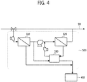
- the desalination device 500 may include a nanofiltration means 510, a reverse osmosis means 520, and an energy recovery means 530.
- the controller 600 may adjust the inflow ratio of the second stored water that is introduced into the desalination device 500 from the pre-treatment device 400 according to the automatic operating algorithm.
- the nanofiltration means 510 may be operated with high flux, and because the second stored water introduced into the reverse osmosis means 520 is water from which organic matter is removed one more time through the nanofiltration means 510, the reverse osmosis means 520 may also be operated with high flux.
- a membrane fouling phenomenon may be intensified if organic matter contained in introduced water has a high concentration.
- the inventive concept may prevent this problem by removing organic matter from the second stored water and may thus provide an effect of stably operating the treatment facility.
- the nanofiltration means 510 filters the second stored water pre-treated in and introduced from the pre-treatment device 400 and releases produced water and concentrated water.
- the nanofiltration means 510 may preferably include a plurality of nanofiltration (NF) membranes arranged and installed therein.
- the reverse osmosis means 520 may produce a larger amount of produced water at the same water pressure because the hardness is controlled, and the treatment facility may be more stably operated in a high flux condition because the organics are controlled.
- the reverse osmosis means 520 filters pressurized filtered-water released from a high-pressure pump by using a reverse osmosis method and releases produced water and concentrated water.
- the reverse osmosis means 520 may preferably include a plurality of reverse osmosis (RO) membranes arranged and installed therein.
- the membranes applied to the reverse osmosis means 520 are brackish water reverse osmosis (BWRO) membranes having high flux efficiency. That is, the reverse osmosis facility may be operated with higher flux when the same water pressure is applied. Accordingly, a larger amount of produced water may be produced with regard to the same membrane area, and thus the size of the desalination device 500 may be reduced.
- BWRO brackish water reverse osmosis
- the concentrated water of the nanofiltration means 510 and the reverse osmosis means 520 may be introduced into the dehydration means 490.
- the energy recovery means 530 is a component that is operated by the concentrated water released from the reverse osmosis means 520 to recover energy.
- the energy recovery means 530 may include any one selected from a Pelton turbine, Francis turbine, and a turbocharger turbine, as an energy recovery device (ERD).
- the desalination device 500 of the inventive concept may be selectively operated only in case of drought. Hence, the desalination device 500 may be installed so as to be easily combined with or detached from the pre-treatment device 400. Furthermore, the desalination device 500 may be easily moved for usage in another place according to necessity because the facility size of the desalination device 500 is small.
- the desalination device 500 may be intermittently operated, the desalination device 500 may be easily exposed to a sudden water pressure change and corrosion, which may cause a problem in terms of durability. Therefore, the desalination device 500 may preferably be designed to increase the durability thereof by using a pump capable of gradually regulating pressure and a material having high resistance to corrosion.
- the produced water released from the desalination device 500 may be introduced into the chlorine treatment means 480 and mixed with the second stored water not passing through the desalination device 500, after which the mixture of the produced water and the second stored water may be treated with chlorine and then released as potable water.
- the controller 600 may control an overall operation of the water supply management system 100 by reflecting the automatic operating algorithm.
- the controller 600 may obtain the water level of the water supply source and may determine a drought situation, a normal situation, and a flood situation.
- the controller 600 may determine the drought situation when the current water level A of the water supply source is lower than a preset first water level B.
- the controller 600 determines an initial drought situation when the current water level A of the water supply source is lower than the preset first water level B and higher than a preset second water level C (water-intake level), and the controller 600 determines a severe drought situation when the current water level A of the water supply source is lower than the preset second water level C.
- the controller 600 may determine the drought situation and may adjust the inflow rate of the freshwater 20 introduced from the water supply source and the inflow rate of the first stored water introduced from the first water storage tank 100.
- Severe Drought A ⁇ C 0 Q1 Q1
- the flow rate of water taken into a water purification plant is Q1 in the normal situation.
- the first stored water is introduced into the second water storage tank 200 to supplement the flow-rate reduction.
- the flow rate reduced after operation of the desalination facility is supplemented by increasing the flow rate of the first stored water.
- the first stored water may have a high salinity, and therefore the salinity of the first stored water needs to be lowered.
- the controller 600 may set a target outflow rate of potable water and a target salinity of the potable water first.
- controller 600 may measure the salinities of the currently introduced freshwater 20 and the first stored water and may calculate the salinity of the second stored water that is stored in the second water storage tank 200.
- the controller 600 determines the inflow ratio of the second stored water through first calculation using the following Equation 1 in the process in which all or part of the second stored water passing through the pre-treatment device 400 is introduced into the desalination device 500.
- Q2 denotes the outflow rate of the second stored water passing through the pre-treatment device 400
- Q3 denotes the inflow rate of the second stored water introduced into the desalination device 500
- Q4 denotes the inflow rate of the second stored water not introduced into the desalination device 500
- C2 denotes the salinity of the second stored water passing through the pre-treatment device 400
- C3 denotes the salinity of the second stored water introduced into the desalination device 500
- C4 denotes the salinity of the second stored water not introduced into the desalination device 500
- Y denotes a target recovery rate in the desalination device 500
- R denotes a removal rate in the desalination device 500
- C target denotes the target salinity of the potable water.
- the first calculation is a rough calculation for determining the initial inflow ratio of the second stored water into the desalination device 500.
- the value of x that is, the inflow ratio of the second stored water introduced into the desalination device 500 may be roughly calculated by solving Equation 1.
- the final salinity of the potable water has to be lower than the target salinity of the potable water, and the inflow ratio of the second stored water into the desalination device 500 may be adjusted correspondingly.
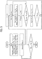
- the controller 600 may calculate pressure required for a process of the desalination device 500 by reflecting the desalination performance as illustrated in FIG. 5 and may calculate the flow rate and salinity of produced water of the desalination device 500 according to the desalination performance.
- J W denotes treated water flux and may be defined by the following Equation 2
- Q p denotes the outflow rate of the produced water and may be defined by the following Equation 3
- J s denotes salt flux and may be defined by the following Equation 4
- C p denotes the salinity of the produced water and may be defined by the following Equation 5.
- J w A ⁇ TCF P b ⁇ P p ⁇ CPF ⁇ ⁇ b ⁇ p
- Q p J w ⁇ Area
- TCF denotes a temperature correction factor
- CPF denotes a concentration polarization factor
- P denotes water pressure
- ⁇ denotes osmotic pressure
- Q denotes a flow rate
- C denotes salinity
- J denotes flux
- w denotes water
- s denotes salt
- b denotes bulk
- p denotes permeate
- Area denotes a membrane area
- A denotes a water permeability coefficient
- B denotes a salt permeability coefficient.
- the controller 600 may calculate the outflow rate and salinity of the produced water in the desalination device 500 according to the desalination performance. Furthermore, based on the outflow rate and salinity of the produced water, the controller 600 may calculate the final outflow rate and the final salinity of the potable water in which the produced water of the desalination device 500 and the second stored water not passing through the desalination device 500 are mixed.
- the controller 600 may adjust the inflow rate of the first stored water from the first water storage tank 100.
- the controller 600 decreases the inflow rate of the first stored water from the first water storage tank 100 when the final outflow rate of the potable water is higher than the target outflow rate of the potable water, and the controller 600 increases the inflow rate of the first stored water from the first water storage tank 100 when the final outflow rate of the potable water is lower than the target outflow rate of the potable water.
- controller 600 may identify and adjust the salinity of the potable water when the final outflow rate of the potable water is within a set target range, compared with the target outflow rate of the potable water.
- the controller 600 further increases the inflow ratio of the second stored water introduced into the desalination device 500 when the final salinity of the potable water is much higher than the target salinity of the potable water, and the controller 600 decreases the inflow ratio of the second stored water introduced into the desalination device 500 when the final salinity of the potable water is much lower than the target salinity of the potable water.
- the controller 600 may preferably reduce the inflow rate of the second stored water introduced into the desalination device 500 in terms of economy.
- FIG. 6A and FIG. 6B is a flowchart illustrating the water supply management method according to the embodiment of the inventive concept.
- the water supply management method includes a step of determining a drought situation (S10), a step of introducing freshwater and first stored water into the second water storage tank 200 in the drought situation (S20, S30, S40, S50, S60, S70, S80, and S90), a step of determining a normal situation (S100), a step of closing the rainwater inflow pipe 33, the first stored water inflow pipe 40, the seawater inflow pipe 60, and the first stored water drain pipe 50 in the normal situation (S110), a step of determining a flood situation (S200), and a step of opening the rainwater inflow pipe 33 in the flood situation and opening the first stored water drain pipe 50 when the water level of the first stored water in the first water storage tank 100 is higher than or equal to a preset value (S210).
- S10 a step of determining a drought situation
- S10 a step of introducing freshwater and first stored water into the second water storage tank 200 in the drought situation
- S100 a step of determining a normal
- the controller 600 may obtain the water level of the water supply source and may determine the drought situation, the normal situation, and the flood situation.
- the controller 600 may determine the drought situation when the current water level A of the water supply source is lower than the preset first water level B.
- the controller 600 determines an initial drought situation when the current water level A of the water supply source is lower than the preset first water level B and higher than the preset second water level C (water-intake level), and the controller 600 determines a severe drought situation when the current water level A of the water supply source is lower than the preset second water level C.
- the step of introducing the freshwater and the first stored water into the second water storage tank 200 in the drought situation may include a step of setting a target outflow rate of potable water and a target salinity of the potable water (S20), a step of opening, by the controller 600, the first stored water inflow pipe 40 to introduce the first stored water in the first water storage tank 100 into the second water storage tank 200 and determining an inflow rate of the first stored water and an inflow rate of the freshwater based on the current water level A of the water supply source (S30), a step of calculating, by the controller 600, the salinity of second stored water that is stored in the second water storage tank 200 (S40), a step of determining, by the controller 600, the inflow ratio of the second stored water introduced into the desalination device 500 to the second stored water subjected to a pre-treatment process in the pre-treatment device 400, through first calculation (S50),
- the controller 600 may set the target outflow rate of the potable water and the target salinity of the potable water first.
- the first stored water is introduced into the second water storage tank 200 to supplement the flow-rate reduction.
- the controller 600 may measure the salinities of the currently introduced freshwater and the first stored water and may calculate the salinity of the second stored water that is stored in the second water storage tank 200.
- the controller 600 determines the inflow ratio of the second stored water through the first calculation using the following Equation 6 in the process in which all or part of the second stored water passing through the pre-treatment device 400 is introduced into the desalination device 500, because a slight flow loss occurs when the second stored water is subjected to the pre-treatment (water purification) process.
- Q2 denotes the outflow rate of the second stored water passing through the pre-treatment device 400
- Q3 denotes the inflow rate of the second stored water introduced into the desalination device 500
- Q4 denotes the inflow rate of the second stored water not introduced into the desalination device 500
- C2 denotes the salinity of the second stored water passing through the pre-treatment device 400
- C3 denotes the salinity of the second stored water introduced into the desalination device 500
- C4 denotes the salinity of the second stored water not introduced into the desalination device 500
- Y denotes a target recovery rate in the desalination device 500
- R denotes a removal rate in the desalination device 500
- C target denotes the target salinity of the potable water.
- the first calculation is a rough calculation for determining the initial inflow ratio of the second stored water into the desalination device 500.
- the value of x that is, the inflow ratio of the second stored water introduced into the desalination device 500 may be roughly calculated by solving Equation 6.
- the final salinity of the potable water has to be lower than the target salinity of the potable water, and the inflow ratio of the second stored water into the desalination device 500 may be adjusted correspondingly.
- the controller 600 may calculate pressure required for a process of the desalination device 500 by reflecting the desalination performance as illustrated in FIG. 5 and may calculate the flow rate and salinity of the produced water of the desalination device 500 according to the desalination performance, because the flow rate and salinity of the second stored water introduced into the desalination device 500 are calculated.
- J W denotes treated water flux and may be defined by the following Equation 7
- Q p denotes the outflow rate of the produced water and may be defined by the following Equation 8
- J s denotes salt flux and may be defined by the following Equation 9
- C p denotes the salinity of the produced water and may be defined by the following Equation 10.
- TCF denotes a temperature correction factor
- CPF denotes a concentration polarization factor
- P denotes water pressure
- ⁇ denotes osmotic pressure
- Q denotes a flow rate
- C denotes salinity
- J denotes flux
- w denotes water
- s denotes salt
- b denotes bulk
- p denotes permeate
- Area denotes a membrane area
- A denotes a water permeability coefficient
- B denotes a salt permeability coefficient.
- the controller 600 may calculate the outflow rate and salinity of the produced water in the desalination device 500 according to the desalination performance.
- the controller 600 may calculate the final outflow rate and the final salinity of the potable water in which the produced water of the desalination device 500 and the second stored water not passing through the desalination device 500 are mixed.
- the controller 600 may adjust the inflow rate of the first stored water from the first water storage tank 100 when the final outflow rate of the potable water is much higher or lower than the target outflow rate of the potable water.
- the controller 600 decreases the inflow rate of the first stored water from the first water storage tank 100 when the final outflow rate of the potable water is higher than the target outflow rate of the potable water, and the controller 600 increases the inflow rate of the first stored water from the first water storage tank 100 when the final outflow rate of the potable water is lower than the target outflow rate of the potable water.
- the controller 600 may identify and adjust the salinity of the potable water when the final outflow rate of the potable water is within a set target range, compared with the target outflow rate of the potable water.
- the controller 600 further increases the inflow ratio of the second stored water introduced into the desalination device 500 when the final salinity of the potable water is much higher than the target salinity of the potable water, and the controller 600 decreases the inflow ratio of the second stored water introduced into the desalination device 500 when the final salinity of the potable water is much lower than the target salinity of the potable water.
- the controller 600 may preferably reduce the inflow rate of the second stored water introduced into the desalination device 500 in terms of economy.
- the above-described water supply management method may be recorded in a computer-readable recording medium including instructions for performing the method and may be read out of a computer by a user.
- the embodiment of the inventive concept may be written in various languages and may be reorganized to be suitable for a specific environment.
- the embodiment of the inventive concept may be written in assembly language and the C programming language, and in various 32-bit processors or generic-purpose computers, the embodiment of the inventive concept may be written in a variety of available programs.
- the water supply management system and method may stably ensure potable water in a drought situation and may rapidly drain rainwater overflowing in a flood situation.
Landscapes
- Engineering & Computer Science (AREA)
- Water Supply & Treatment (AREA)
- Health & Medical Sciences (AREA)
- Life Sciences & Earth Sciences (AREA)
- Hydrology & Water Resources (AREA)
- Business, Economics & Management (AREA)
- Public Health (AREA)
- Environmental & Geological Engineering (AREA)
- Economics (AREA)
- Tourism & Hospitality (AREA)
- Organic Chemistry (AREA)
- Chemical & Material Sciences (AREA)
- Primary Health Care (AREA)
- General Health & Medical Sciences (AREA)
- Marketing (AREA)
- Physics & Mathematics (AREA)
- General Business, Economics & Management (AREA)
- General Physics & Mathematics (AREA)
- Theoretical Computer Science (AREA)
- Strategic Management (AREA)
- Human Resources & Organizations (AREA)
- Structural Engineering (AREA)
- Educational Administration (AREA)
- Development Economics (AREA)
- Separation Using Semi-Permeable Membranes (AREA)
- Water Treatment By Sorption (AREA)
Abstract
Description
- Embodiments of the inventive concept described herein relate to a water supply management system and method and a computer-readable recording medium including instructions for performing the method.
- The importance of water resources has been emphasized all over the world. Most of water resources of our country depend on rivers, and the amount of rainfall has an influence on environments and water qualities of the rivers.
- In recent years, due to climate change, areas prone to floods according to regional torrential rains have been expanded, or water shortages have been caused by repeated droughts.
- That is, the quantities and qualities of water resources are changing every year due to changing external environments, and therefore managing water through existing water supply management systems is becoming more difficult. For example, in case of drought, it is difficult to ensure drinking water resources through existing water treatment facilities due to lack of water entering water supply sources, and in case of flood, downtown areas are often flooded, and rivers overflow frequently.
- Accordingly, a new water supply management system for reducing damage due to climate change is required.
- Embodiments of the inventive concept provide a water supply management system and method for preparing for drought and flood by connecting an underground water tank, a desalination facility, and a rainwater pipe with an existing water purification facility, and a computer-readable recording medium including instructions for performing the method.
- The technical problems to be solved by the inventive concept are not limited to the aforementioned problems, and any other technical problems not mentioned herein will be clearly understood from the following description by those skilled in the art to which the inventive concept pertains.
- According to an exemplary embodiment, a water
supply management system 1000 includes a firstwater storage tank 100, a secondwater storage tank 200, awater treatment device 300, and acontroller 600 that controls opening or closing of inflow pipes and drain pipes connected to the firstwater storage tank 100, the secondwater storage tank 200, and thewater treatment device 300. The firstwater storage tank 100 stores first stored water, and at least one ofrainwater 30 andseawater 10 overflowing in case of flood is introduced into the firstwater storage tank 100 to form the first stored water. The secondwater storage tank 200 stores second stored water, and at least one offreshwater 20 in a water supply source and the first stored water in the firstwater storage tank 100 is introduced into the secondwater storage tank 200 to form the second stored water. Thewater treatment device 300 purifies the second stored water released from the secondwater storage tank 200 and releases potable water. Thecontroller 600 controls inflow rates and outflow rates of therainwater 30, theseawater 10, thefreshwater 20, the first stored water, the second stored water, and the potable water. - The first
water storage tank 100 may include a rainwater inflow pipe 33 through which therainwater 30 is introduced into thefirst storage tank 100, a first storedwater inflow pipe 40 through which the first stored water is introduced into the secondwater storage tank 200,seawater inflow pipes seawater 10 is introduced into the firstwater storage tank 100, and a first storedwater drain pipe 50 through which the first stored water is released to the sea. - The
controller 600 maycontrol valves water inflow pipe 40, theseawater inflow pipes water drain pipe 50, respectively, and thecontroller 600 maycontrol pumps water inflow pipe 40 and the first storedwater drain pipe 50, respectively. - The
controller 600 may determine a normal situation, a drought situation, or a flood situation, based on a water level of the water supply source. In the normal situation, thecontroller 600 may close the rainwater inflow pipe 33, the first storedwater inflow pipe 40, theseawater inflow pipes water drain pipe 50. In the drought situation, thecontroller 600 may open theseawater inflow pipes water inflow pipe 40 and may close the first storedwater drain pipe 50. In the flood situation, thecontroller 600 may open the rainwater inflow pipe 33, and thecontroller 600 may open the first storedwater drain pipe 50 when a water level of the first stored water in the firstwater storage tank 100 is higher than or equal to a preset value. - A foreign
material removal device 70 may be disposed in theseawater inflow pipes seawater 10. The removed foreign matter may be discharged to the sea through the first storedwater drain pipe 50. - The foreign
material removal device 70 may include ahousing 70a including aseawater inlet 70b, aseawater outlet 70c, and aforeign matter outlet 70d,blades seawater 10 introduced from the sea, amesh screen 72 that filters foreign matter floating in thehousing 70a, andscrapers mesh screen 72 and a sidewall of thehousing 70a. - The
water treatment device 300 may include apre-treatment device 400 that includes a coagulation means 420, a sedimentation means 430, and a filtration means 440 and that controls water quality of the second stored water, and adesalination device 500 that is disposed downstream of thepre-treatment device 400 and that removes dissolved matter containing salt from part of the second stored water and releases produced water. - The
pre-treatment device 400 may further include an ozone treatment means 460 and an activated carbon treatment means 470. - The
desalination device 500 may include a nanofiltration means 510 and a reverse osmosis means 520. - The
desalination device 500 may be combinable with or detachable from thepre-treatment device 400. Thecontroller 600 may combine thedesalination device 500 with thepre-treatment device 400 in the drought situation, and thecontroller 600 may detach thedesalination device 500 from thepre-treatment device 400 in the normal situation. - The
controller 600 may determine the drought situation when a current water level A of the water supply source is lower than a first water level B, may set a target outflow rate of the potable water and a target salinity of the potable water, may open the first storedwater inflow pipe 40 to introduce the first stored water in the firstwater storage tank 100 into the secondwater storage tank 200, may determine an inflow rate of the first stored water and an inflow rate of thefreshwater 20 based on the current water level A of the water supply source, may measure salinities of thefreshwater 20 and the first stored water, may calculate a salinity of the second stored water that is stored in the secondwater storage tank 200, determine an inflow ratio of the second stored water introduced into thedesalination device 500 to the second stored water subjected to a pre-treatment process in thepre-treatment device 400, through first calculation, may reflect desalination performance of thedesalination device 500 to determine an outflow rate and a salinity of the produced water released from thedesalination device 500, through second calculation, may determine a final outflow rate and a final salinity of the potable water released from thewater treatment device 300, through third calculation, may compare the target outflow rate of the potable water and the final outflow rate of the potable water, may adjust the inflow rate of the first stored water, may compare the target salinity of the potable water and the final salinity of the potable water, and may adjust the inflow ratio of the second stored water introduced into thedesalination device 500. - According to an exemplary embodiment, a water supply management method includes a step of obtaining, by the
controller 600, a current water level of a water supply source and determining a drought situation, a normal situation, and a flood situation based on the current water level of the water supply source (S10), a step of adjusting, by thecontroller 600, an inflow rate offreshwater 20 from the water supply source and an inflow rate of first stored water from the firstwater storage tank 100 and introducing thefreshwater 20 and the first stored water into the secondwater storage tank 200, when thecontroller 600 determines the drought situation, a step of closing, by thecontroller 600, the rainwater inflow pipe 33, the first storedwater inflow pipe 40, theseawater inflow pipes water drain pipe 50, when thecontroller 600 determines the normal situation (S110), and a step of opening, by thecontroller 600, the rainwater inflow pipe 33 when thecontroller 600 determines the flood situation, and opening the first storedwater drain pipe 50 when a water level of the first stored water in the firstwater storage tank 100 is higher than or equal to a preset value (S210). - The step of introducing the
freshwater 20 and the first stored water into the secondwater storage tank 200 may include a step of setting, by thecontroller 600, a target outflow rate of potable water and a target salinity of the potable water (S20), a step of opening, by thecontroller 600, the first storedwater inflow pipe 40 to introduce the first stored water in the firstwater storage tank 100 into the secondwater storage tank 200 and determining an inflow rate of the first stored water and an inflow rate of thefreshwater 20 based on the current water level of the water supply source (S30), a step of calculating, by thecontroller 600, a salinity of second stored water that is stored in the second water storage tank 200 (S40), a step of determining, by thecontroller 600, an inflow ratio of the second stored water introduced into thedesalination device 500 to the second stored water subjected to a pre-treatment process in thepre-treatment device 400, through first calculation (S50), a step of reflecting, by thecontroller 600, desalination performance of thedesalination device 500 and determining an outflow rate and a salinity of produced water released from thedesalination device 500, through second calculation (S60), a step of determining, by thecontroller 600, a final outflow rate and a final salinity of the potable water released from thewater treatment device 300, through third calculation (S70), a step of comparing, by thecontroller 600, the target outflow rate of the potable water and the final outflow rate of the potable water and adjusting the inflow rate of the first stored water (S80), and a step of comparing, by thecontroller 600, the target salinity of the potable water and the final salinity of the potable water and adjusting the inflow ratio of the second stored water introduced into the desalination device 500 (S90). - In the step of comparing, by the
controller 600, the target outflow rate of the potable water and the final outflow rate of the potable water and adjusting the inflow rate of the first stored water (S80), thecontroller 600 may decrease the inflow rate of the first stored water from the firstwater storage tank 100 when the final outflow rate of the potable water is higher than the target outflow rate of the potable water, and thecontroller 600 may increase the inflow rate of the first stored water from the firstwater storage tank 100 when the final outflow rate of the potable water is lower than the target outflow rate of the potable water. In the step of comparing, by thecontroller 600, the target salinity of the potable water and the final salinity of the potable water and adjusting the inflow ratio of the second stored water introduced into the desalination device 500 (S90), thecontroller 600 may determine that the final outflow rate of the potable water is within a set target range, compared with the target outflow rate of the potable water, after which thecontroller 600 may further increase the inflow ratio of the second stored water introduced into thedesalination device 500 when the final salinity of the potable water is much higher than the target salinity of the potable water and thecontroller 600 may decrease the inflow ratio of the second stored water introduced into thedesalination device 500 when the final salinity of the potable water is much lower than the target salinity of the potable water. - The above and other objects and features will become apparent from the following description with reference to the following figures, wherein like reference numerals refer to like parts throughout the various figures unless otherwise specified, and wherein:
-
FIG. 1 is a schematic view illustrating a configuration of a water supply management system according to an embodiment of the inventive concept; -
FIG. 2 is a schematic view illustrating a configuration of a foreign material removal device ofFIG. 1 ; -
FIG. 3 is a schematic view illustrating a configuration of a water treatment device ofFIG. 1 ; -
FIG. 4 is a schematic view illustrating a configuration of a desalination device ofFIG. 3 ; -
FIG. 5 is a flowchart illustrating a process of calculating the outflow rate and salinity of produced water by reflecting desalination performance of the desalination device; and -
FIG. 6A andFIG. 6B is a flowchart illustrating a water supply management method according to an embodiment of the inventive concept. - Hereinafter, embodiments of the inventive concept will be described in more detail with reference to the accompanying drawings. The inventive concept may, however, be embodied in different forms and should not be constructed as limited to the embodiments set forth herein. Rather, these embodiments are provided so that the inventive concept will be thorough and complete, and will fully convey the scope of the inventive concept to those skilled in the art. In the drawings, the dimensions of components are exaggerated for clarity of illustration.
- In order to clarify the solutions of the inventive concept to the problems, the configuration of the inventive concept will be described in detail with reference to the accompanying drawings, based on the embodiments of the inventive concept. In adding the reference numerals to the components of each drawing, it should be noted that the identical or equivalent component is designated by the identical numeral even when they are displayed on other drawings, and when any drawing is explained, a component depicted in another drawing may be recited, if necessary.
- Hereinafter, a water supply management system according to an embodiment of the inventive concept will be described with reference to
FIGS. 1 to 5 . -
FIG. 1 is a schematic view illustrating a configuration of the water supply management system according to the embodiment of the inventive concept.FIG. 2 is a schematic view illustrating a configuration of a foreign material removal device ofFIG. 1 .FIG. 3 is a schematic view illustrating a configuration of a water treatment device ofFIG. 1 .FIG. 4 is a schematic view illustrating a configuration of a desalination device ofFIG. 3 .FIG. 5 is a flowchart illustrating a process of calculating the outflow rate and salinity of produced water by reflecting desalination performance of the desalination device. - Referring to
FIG. 1 , the watersupply management system 1000 according to the embodiment of the inventive concept includes a firstwater storage tank 100, a secondwater storage tank 200, thewater treatment device 300, and acontroller 600. - The first
water storage tank 100 may store first stored water in whichseawater 10 andrainwater 30 are mixed. The firstwater storage tank 100 may preferably be disposed in a lower position than the level of theseawater 10 to allow theseawater 10 to be easily introduced into the firstwater storage tank 100. - A rainwater inflow pipe 33 may be connected to one side of the first
water storage tank 100, and therainwater 30 that overflows in case of flood in acity 1 may be introduced into the firstwater storage tank 100 through the rainwater inflow pipe 33. A first storedwater drain pipe 50 andseawater inflow pipes water storage tank 100. The first stored water may be released to the sea through the first storedwater drain pipe 50, and theseawater 10 may be introduced into the firstwater storage tank 100 through theseawater inflow pipes water inflow pipe 40 may be connected to the top side of the firstwater storage tank 100, and the first stored water may be introduced into the secondwater storage tank 200 from the firstwater storage tank 100 through the first storedwater inflow pipe 40. -
Pumps water drain pipe 50 and the first storedwater inflow pipe 40, respectively. -
Valves water inflow pipe 40, the first storedwater drain pipe 50, and theseawater inflow pipes valve 32 may control the inflow rate of therainwater 30, thevalves valve 61 may control the inflow rate of theseawater 10. - The
controller 600 may control thevalves water drain pipe 50, the first storedwater inflow pipe 40, and theseawater inflow pipe 60, respectively. - Meanwhile, the
rainwater 30 that overflows in case of flood in thecity 1 may be introduced into a water supply source along a rainwater pipe 31, and when therainwater inlet valve 32 is opened under the control of thecontroller 600, therainwater 30 may be introduced into the firstwater storage tank 100 through the rainwater inflow pipe 33. Here, therainwater 30 not introduced into the rainwater inflow pipe 33 may be drained through a rainwater drain pipe 34 and mixed withfreshwater 20. - Although not illustrated, foreign matter in the introduced
rainwater 30 may preferably be removed through a separate filter. - Furthermore, the foreign
material removal device 70 for removing foreign matter contained in the introducedseawater 10 may be included in theseawater inflow pipes - Referring to
FIG. 2 , the foreignmaterial removal device 70 may include ahousing 70a,blades mesh screen 72, andscrapers - The
housing 70a may include aseawater inlet 70b through which theseawater 10 is introduced into thehousing 70a, aseawater outlet 70c through which theseawater 10 is drained from thehousing 70a, aforeign matter outlet 70d, and sidewalls for storing theseawater 10. - The
blades housing 70a so as to be adjacent to theseawater inlet 70b and theforeign matter outlet 70d, respectively. - The
blades seawater 10 and may repeatedly operate and stop to generate a vortex in theseawater 10, thereby enabling fragments of the broken foreign matter to be easily discharged through theforeign matter outlet 70d. - The
foreign matter outlet 70d may include a funnel-shapedspace 75 having a predetermined slope and may guide a discharge path of the foreign matter that is discharged. - The
mesh screen 72 may have a mesh shape. Themesh screen 72 may allow theseawater 10 to pass through and may filter the floating foreign matter from theseawater 10. - The
scrapers mesh screen 72 and an inner side of thehousing 70a, respectively, and may vertically move to scrape stuck objects such as barnacles off themesh screen 72 and thehousing 70a. - The foreign matter discharged together with the
seawater 10 through theforeign matter outlet 70d may be introduced into the first storedwater drain pipe 50 through a foreignmatter discharge pipe 80. - A foreign matter discharge valve 81 may be disposed in the foreign
matter discharge pipe 80. - The second
water storage tank 200 may store second stored water in which thefreshwater 20 of the water supply source and the first stored water of the firstwater storage tank 100 are mixed. - In the case where the first stored
water intake pump 41 does not operate or theinlet valve 42 is closed so that the first stored water is not introduced into the secondwater storage tank 200, only thefreshwater 20 may be stored in the secondwater storage tank 200. - The
controller 600 may measure the water level of the water supply source and may determine a normal situation, a drought situation, or a flood situation. - When the
controller 600 determines the drought situation according to an automatic operating algorithm, thecontroller 600 may operate theintake pump 41 and open theinlet valve 42 such that the first stored water is introduced into the secondwater storage tank 200, and when thecontroller 600 determines the normal situation or the flood situation, thecontroller 600 may stop theintake pump 41 and close theinlet valve 42 such that the first stored water is not introduced into the secondwater storage tank 200. - The automatic operating algorithm of the
controller 600 will be described in detail in the description of thecontroller 600. - The first stored
water inflow pipe 40 and afreshwater inflow pipe 22 may be connected to one side of the secondwater storage tank 200, and a second stored water drain pipe may be connected to an opposite side of the secondwater storage tank 200. The first stored water in the firstwater storage tank 100 may be introduced into the secondwater storage tank 200 through the first storedwater inflow pipe 40. Thefreshwater 20 in the water supply source may be introduced into the secondwater storage tank 200 through thefreshwater inflow pipe 22. The second stored water in the secondwater storage tank 200 may be released to thewater treatment device 300 through the second stored water drain pipe. - A
pump 21 for a flow of thefreshwater 20 may be disposed in thefreshwater inflow pipe 22. - The second stored water in the second
water storage tank 200 may be introduced into thewater treatment device 300, and thewater treatment device 300 may release potable water purified through water-quality improvement pre-treatment and desalination. The potable water purified through thewater treatment device 300 may be introduced into thecity 1 through a potablewater inflow pipe 90. - The
water treatment device 300 includes apre-treatment device 400 and thedesalination device 500. - The
desalination device 500 may be combined with or detached from thepre-treatment device 400 under the control of thecontroller 600. - For example, in the drought situation, the
controller 600 may combine thepre-treatment device 400 and thedesalination device 500, and in the normal situation or the flood situation, thecontroller 600 may detach thedesalination device 500 from thepre-treatment device 400. - Referring to
FIG. 3 , thepre-treatment device 400 may include a receiving well 410, a coagulation means 420, a sedimentation means 430, a filtration means 440, a membrane filtration means 450, an ozone treatment means 460, an activated carbon treatment means 470, a chlorine treatment means 480, and a dehydration means 490. - The receiving well 410 is a component into which the second stored water is introduced. The receiving well 410 adjusts the amount of second stored water introduced and uniformly maintains the amount of raw water that is supplied to a water treatment process, thereby allowing processes such as introducing chemicals, filtration, sedimentation, and the like to be effectively performed.
- The receiving well 410 may include an overflow pipe or an overflow weir for preventing the water level from being excessively raised, and may further include a screen for removing floating materials.
- The coagulation means 420 is a component in which foreign matter (e.g., sludge, debris, or the like) contained in the second stored water is coagulated by coagulant. The coagulation means 420 may be subordinate to a mixing basin (not illustrated).
- The sedimentation means 430 is a component in which the foreign matter coagulated by the coagulant is deposited.
- The filtration means 440 is a component that removes organic matter and nutritive salts through a biological reaction that causes the introduced second stored water to react with microorganisms, and that oxidizes and filters ammonia nitrogen.
- The membrane filtration means 450 may be selected separately from processes after the receiving well 410 and may perform a membrane separation process on the second stored water introduced. The membrane filtration means 450 may be based on a microfiltration (MF) membrane or an ultrafiltration (UF) membrane and may include an inflow pipe through which the second stored water is introduced into the membrane filtration means 450, a membrane filtration unit (a separation membrane), chemical piping, backwash piping, and the like.
- The second stored water having passed through the sedimentation means 430 or the membrane filtration means 450 passes through the ozone treatment means 460 and the activated carbon treatment means 470.
- The ozone treatment means 460 is a component that injects ozone into the second stored water and performs an ozone reaction on the second stored water. The ozone treatment means 460 includes an ozone reaction tank in which the ozone reaction is performed and an ozone generator that generates and injects ozone into the ozone reaction tank.
- The ozone treatment means 460 uses ozone (O3) having strong oxidation power to remove organic matter that is not well removed in a standard secondary treatment process and change properties of taste/odor-causing substances in the second stored water such that the taste/odor-causing substances are well adsorbed onto activated carbon.
- The activated carbon treatment means 470 is a component that performs activated carbon treatment on the second stored water. The activated carbon treatment means 470 removes foreign matter (e.g., organic matter, taste/odor-causing substances, phenols, or the like) that are contained in the second stored water.
- The activated carbon treatment means 470 may treat the second stored water through a powdered activated carbon process of stirring activated carbon in a powder state into the second stored water and depositing and filtering the activated carbon, a granular activated carbon process of allowing the second stored water to pass through adsorptive carbon constituted by granular carbon, or the like.
- The chlorine treatment means 480 is a component that injects chlorine into the second stored water. The chlorine treatment means 480 uses oxidation and sterilizing action of chlorine to preserve residual chlorine right before the supply of water as well as to destroy germs or bacteria, remove iron or manganese, remove ammonia, or remove taste/odor.
- The dehydration means 490 is a facility that forcibly feeds concentrated sludge generated in the sedimentation means 430 or the membrane filtration means 450 into a
slurry storage tank 95 to maintain moisture content at a predetermined value during operation. At this time, polymer coagulant may be injected into the sludge through a pump to increase dehydration efficiency. - The
desalination device 500 may include a nanofiltration means 510, a reverse osmosis means 520, and an energy recovery means 530. - The
controller 600 may adjust the inflow ratio of the second stored water that is introduced into thedesalination device 500 from thepre-treatment device 400 according to the automatic operating algorithm. - The second stored water introduced into the
desalination device 500 is treated-water that has been pretreated by advanced water purification (ozone and activated carbon) in thepre-treatment device 400. That is, the second stored water from which organic matter is removed may be introduced into thedesalination device 500. - Accordingly, the nanofiltration means 510 may be operated with high flux, and because the second stored water introduced into the reverse osmosis means 520 is water from which organic matter is removed one more time through the nanofiltration means 510, the reverse osmosis means 520 may also be operated with high flux.
- When the nanofiltration means 510 and the reverse osmosis means 520 are operated with high flux, a membrane fouling phenomenon may be intensified if organic matter contained in introduced water has a high concentration. However, the inventive concept may prevent this problem by removing organic matter from the second stored water and may thus provide an effect of stably operating the treatment facility.
- The nanofiltration means 510 filters the second stored water pre-treated in and introduced from the
pre-treatment device 400 and releases produced water and concentrated water. Here, the nanofiltration means 510 may preferably include a plurality of nanofiltration (NF) membranes arranged and installed therein. - The nanofiltration means 510 may be installed upstream of the reverse osmosis means 520 to control hardness and organic matter. Accordingly, the nanofiltration means 510 may previously control the hardness of the second stored water that is introduced into a reverse osmosis membrane of the reverse osmosis means 520 and the concentrations of various organics in the second stored water.
- The reverse osmosis means 520 may produce a larger amount of produced water at the same water pressure because the hardness is controlled, and the treatment facility may be more stably operated in a high flux condition because the organics are controlled.
- The reverse osmosis means 520 filters pressurized filtered-water released from a high-pressure pump by using a reverse osmosis method and releases produced water and concentrated water. Here, the reverse osmosis means 520 may preferably include a plurality of reverse osmosis (RO) membranes arranged and installed therein.
- The membranes applied to the reverse osmosis means 520 are brackish water reverse osmosis (BWRO) membranes having high flux efficiency. That is, the reverse osmosis facility may be operated with higher flux when the same water pressure is applied. Accordingly, a larger amount of produced water may be produced with regard to the same membrane area, and thus the size of the
desalination device 500 may be reduced. - The concentrated water of the nanofiltration means 510 and the reverse osmosis means 520 may be introduced into the dehydration means 490.
- The energy recovery means 530 is a component that is operated by the concentrated water released from the reverse osmosis means 520 to recover energy. The energy recovery means 530 may include any one selected from a Pelton turbine, Francis turbine, and a turbocharger turbine, as an energy recovery device (ERD).
- The
desalination device 500 of the inventive concept may be selectively operated only in case of drought. Hence, thedesalination device 500 may be installed so as to be easily combined with or detached from thepre-treatment device 400. Furthermore, thedesalination device 500 may be easily moved for usage in another place according to necessity because the facility size of thedesalination device 500 is small. - That is, because the
desalination device 500 is intermittently operated, thedesalination device 500 may be easily exposed to a sudden water pressure change and corrosion, which may cause a problem in terms of durability. Therefore, thedesalination device 500 may preferably be designed to increase the durability thereof by using a pump capable of gradually regulating pressure and a material having high resistance to corrosion. - Meanwhile, the produced water released from the
desalination device 500 may be introduced into the chlorine treatment means 480 and mixed with the second stored water not passing through thedesalination device 500, after which the mixture of the produced water and the second stored water may be treated with chlorine and then released as potable water. - As described above, the
controller 600 may control an overall operation of the watersupply management system 100 by reflecting the automatic operating algorithm. - The
controller 600 may obtain the water level of the water supply source and may determine a drought situation, a normal situation, and a flood situation. - Especially, the
controller 600 may determine the drought situation when the current water level A of the water supply source is lower than a preset first water level B. - The
controller 600 determines an initial drought situation when the current water level A of the water supply source is lower than the preset first water level B and higher than a preset second water level C (water-intake level), and thecontroller 600 determines a severe drought situation when the current water level A of the water supply source is lower than the preset second water level C. - As listed in Table 1 below, the
controller 600 may determine the drought situation and may adjust the inflow rate of thefreshwater 20 introduced from the water supply source and the inflow rate of the first stored water introduced from the firstwater storage tank 100.[Table 1] Inflow Rate of Freshwater Inflow Rate of First Stored water Inflow Rate of Second Stored water Normal: A ≥ B Q1 0 Q1 Initial Drought: C ≤ A < B 

Q1 Severe Drought: A < C 0 Q1 Q1 - That is, the flow rate of water taken into a water purification plant is Q1 in the normal situation. When the flow rate of the
freshwater 20 introduced from the water supply source is lower than the existing inflow rate according to the drought situation, the first stored water is introduced into the secondwater storage tank 200 to supplement the flow-rate reduction. The flow rate reduced after operation of the desalination facility is supplemented by increasing the flow rate of the first stored water. Meanwhile, the first stored water may have a high salinity, and therefore the salinity of the first stored water needs to be lowered. Simultaneously, the flow rate of potable water required for thecity 1 has to be provided. Hence, thecontroller 600 may set a target outflow rate of potable water and a target salinity of the potable water first. - Furthermore, the
controller 600 may measure the salinities of the currently introducedfreshwater 20 and the first stored water and may calculate the salinity of the second stored water that is stored in the secondwater storage tank 200. - Meanwhile, because a slight flow loss occurs when the second stored water is subjected to a pre-treatment (water purification) process, the
controller 600 determines the inflow ratio of the second stored water through first calculation using the followingEquation 1 in the process in which all or part of the second stored water passing through thepre-treatment device 400 is introduced into thedesalination device 500.
- Here, Q2 denotes the outflow rate of the second stored water passing through the
pre-treatment device 400, Q3 denotes the inflow rate of the second stored water introduced into thedesalination device 500, Q4 denotes the inflow rate of the second stored water not introduced into thedesalination device 500, C2 denotes the salinity of the second stored water passing through thepre-treatment device 400, C3 denotes the salinity of the second stored water introduced into thedesalination device 500, C4 denotes the salinity of the second stored water not introduced into thedesalination device 500, Y denotes a target recovery rate in thedesalination device 500, R denotes a removal rate in thedesalination device 500, and Ctarget denotes the target salinity of the potable water. - The first calculation is a rough calculation for determining the initial inflow ratio of the second stored water into the
desalination device 500. The value of x, that is, the inflow ratio of the second stored water introduced into thedesalination device 500 may be roughly calculated by solvingEquation 1. - However, the final salinity of the potable water has to be lower than the target salinity of the potable water, and the inflow ratio of the second stored water into the
desalination device 500 may be adjusted correspondingly. Here, it is more advantageous in terms of energy as the inflow ratio of the second stored water into thedesalination device 500 decreases. - Because the flow rate and salinity of the second stored water introduced into the
desalination device 500 are calculated, thecontroller 600 may calculate pressure required for a process of thedesalination device 500 by reflecting the desalination performance as illustrated inFIG. 5 and may calculate the flow rate and salinity of produced water of thedesalination device 500 according to the desalination performance. - In
FIG. 5 , JW denotes treated water flux and may be defined by the following Equation 2, Qp denotes the outflow rate of the produced water and may be defined by the following Equation 3, Js denotes salt flux and may be defined by the following Equation 4, and Cp denotes the salinity of the produced water and may be defined by the following Equation 5.


- Here, TCF denotes a temperature correction factor, CPF denotes a concentration polarization factor, P denotes water pressure, Π denotes osmotic pressure, Q denotes a flow rate, C denotes salinity, J denotes flux, w denotes water, s denotes salt, b denotes bulk, p denotes permeate, Area denotes a membrane area, A denotes a water permeability coefficient, and B denotes a salt permeability coefficient.
- Thereafter, the
controller 600 may calculate the outflow rate and salinity of the produced water in thedesalination device 500 according to the desalination performance. Furthermore, based on the outflow rate and salinity of the produced water, thecontroller 600 may calculate the final outflow rate and the final salinity of the potable water in which the produced water of thedesalination device 500 and the second stored water not passing through thedesalination device 500 are mixed. - Meanwhile, when the final outflow rate of the potable water is much higher or lower than the target outflow rate of the potable water, the
controller 600 may adjust the inflow rate of the first stored water from the firstwater storage tank 100. - That is, the
controller 600 decreases the inflow rate of the first stored water from the firstwater storage tank 100 when the final outflow rate of the potable water is higher than the target outflow rate of the potable water, and thecontroller 600 increases the inflow rate of the first stored water from the firstwater storage tank 100 when the final outflow rate of the potable water is lower than the target outflow rate of the potable water. - Furthermore, the
controller 600 may identify and adjust the salinity of the potable water when the final outflow rate of the potable water is within a set target range, compared with the target outflow rate of the potable water. - That is, the
controller 600 further increases the inflow ratio of the second stored water introduced into thedesalination device 500 when the final salinity of the potable water is much higher than the target salinity of the potable water, and thecontroller 600 decreases the inflow ratio of the second stored water introduced into thedesalination device 500 when the final salinity of the potable water is much lower than the target salinity of the potable water. - Even if the final salinity of the potable water is too low, it does not matter. However, the
controller 600 may preferably reduce the inflow rate of the second stored water introduced into thedesalination device 500 in terms of economy. - Hereinafter, a water supply management method according to an embodiment of the inventive concept will be described with reference to
FIG. 6A andFIG. 6B . -
FIG. 6A andFIG. 6B is a flowchart illustrating the water supply management method according to the embodiment of the inventive concept. - Referring to
FIGS. 1 to 5 together withFIG. 6A andFIG. 6B , the water supply management method according to the embodiment of the inventive concept includes a step of determining a drought situation (S10), a step of introducing freshwater and first stored water into the secondwater storage tank 200 in the drought situation (S20, S30, S40, S50, S60, S70, S80, and S90), a step of determining a normal situation (S100), a step of closing the rainwater inflow pipe 33, the first storedwater inflow pipe 40, theseawater inflow pipe 60, and the first storedwater drain pipe 50 in the normal situation (S110), a step of determining a flood situation (S200), and a step of opening the rainwater inflow pipe 33 in the flood situation and opening the first storedwater drain pipe 50 when the water level of the first stored water in the firstwater storage tank 100 is higher than or equal to a preset value (S210). - The
controller 600 may obtain the water level of the water supply source and may determine the drought situation, the normal situation, and the flood situation. - In the step of determining the drought situation (S10), the
controller 600 may determine the drought situation when the current water level A of the water supply source is lower than the preset first water level B. - The
controller 600 determines an initial drought situation when the current water level A of the water supply source is lower than the preset first water level B and higher than the preset second water level C (water-intake level), and thecontroller 600 determines a severe drought situation when the current water level A of the water supply source is lower than the preset second water level C. - The step of introducing the freshwater and the first stored water into the second water storage tank 200 in the drought situation (S20, S30, S40, S50, S60, S70, S80, and S90) may include a step of setting a target outflow rate of potable water and a target salinity of the potable water (S20), a step of opening, by the controller 600, the first stored water inflow pipe 40 to introduce the first stored water in the first water storage tank 100 into the second water storage tank 200 and determining an inflow rate of the first stored water and an inflow rate of the freshwater based on the current water level A of the water supply source (S30), a step of calculating, by the controller 600, the salinity of second stored water that is stored in the second water storage tank 200 (S40), a step of determining, by the controller 600, the inflow ratio of the second stored water introduced into the desalination device 500 to the second stored water subjected to a pre-treatment process in the pre-treatment device 400, through first calculation (S50), a step of reflecting, by the controller 600, the desalination performance of the desalination device 500 and determining an outflow rate and a salinity of produced water released through the desalination device 500, through second calculation (S60), a step of determining, by the controller 600, the final outflow rate and the final salinity of the potable water released through the water treatment device 300, through third calculation (S70), a step of comparing, by the controller 600, the target outflow rate of the potable water and the final outflow rate of the potable water and adjusting the inflow rate of the first stored water (S80), and a step of comparing, by the controller 600, the target salinity of the potable water and the final salinity of the potable water and adjusting the inflow ratio of the second stored water introduced into the desalination device 500 (S90).
- In the step of setting the target outflow rate of the potable water and the target salinity of the potable water (S20), because it is necessary to lower the salinity of the first stored water introduced into the second
water storage tank 200 in the drought situation and the flow rate of the potable water required for thecity 1 has to be provided, thecontroller 600 may set the target outflow rate of the potable water and the target salinity of the potable water first. - In the step of determining the inflow rate of the first stored water and the inflow rate of the freshwater based on the current water level A of the water supply source (S30), when the inflow rate of the freshwater introduced from the water supply source is lower than the existing inflow rate according to the drought situation, the first stored water is introduced into the second
water storage tank 200 to supplement the flow-rate reduction. - In the step of calculating, by the
controller 600, the salinity of the second stored water that is stored in the second water storage tank 200 (S40), thecontroller 600 may measure the salinities of the currently introduced freshwater and the first stored water and may calculate the salinity of the second stored water that is stored in the secondwater storage tank 200. - In the step of determining, by the
controller 600, the inflow ratio of the second stored water introduced into thedesalination device 500 to the second stored water subjected to the pre-treatment process in thepre-treatment device 400, through the first calculation (S50), thecontroller 600 determines the inflow ratio of the second stored water through the first calculation using the following Equation 6 in the process in which all or part of the second stored water passing through thepre-treatment device 400 is introduced into thedesalination device 500, because a slight flow loss occurs when the second stored water is subjected to the pre-treatment (water purification) process.
- Here, Q2 denotes the outflow rate of the second stored water passing through the
pre-treatment device 400, Q3 denotes the inflow rate of the second stored water introduced into thedesalination device 500, Q4 denotes the inflow rate of the second stored water not introduced into thedesalination device 500, C2 denotes the salinity of the second stored water passing through thepre-treatment device 400, C3 denotes the salinity of the second stored water introduced into thedesalination device 500, C4 denotes the salinity of the second stored water not introduced into thedesalination device 500, Y denotes a target recovery rate in thedesalination device 500, R denotes a removal rate in thedesalination device 500, and Ctarget denotes the target salinity of the potable water. - The first calculation is a rough calculation for determining the initial inflow ratio of the second stored water into the
desalination device 500. The value of x, that is, the inflow ratio of the second stored water introduced into thedesalination device 500 may be roughly calculated by solving Equation 6. - However, the final salinity of the potable water has to be lower than the target salinity of the potable water, and the inflow ratio of the second stored water into the
desalination device 500 may be adjusted correspondingly. Here, it is more advantageous in terms of energy as the inflow ratio of the second stored water into thedesalination device 500 decreases. - In the step of reflecting, by the
controller 600, the desalination performance of thedesalination device 500 and determining the outflow rate and the salinity of the produced water released through thedesalination device 500, through the second calculation (S60), thecontroller 600 may calculate pressure required for a process of thedesalination device 500 by reflecting the desalination performance as illustrated inFIG. 5 and may calculate the flow rate and salinity of the produced water of thedesalination device 500 according to the desalination performance, because the flow rate and salinity of the second stored water introduced into thedesalination device 500 are calculated. - In
FIG. 5 , JW denotes treated water flux and may be defined by the following Equation 7, Qp denotes the outflow rate of the produced water and may be defined by the following Equation 8, Js denotes salt flux and may be defined by the following Equation 9, and Cp denotes the salinity of the produced water and may be defined by the followingEquation 10.


- Here, TCF denotes a temperature correction factor, CPF denotes a concentration polarization factor, P denotes water pressure, Π denotes osmotic pressure, Q denotes a flow rate, C denotes salinity, J denotes flux, w denotes water, s denotes salt, b denotes bulk, p denotes permeate, Area denotes a membrane area, A denotes a water permeability coefficient, and B denotes a salt permeability coefficient.
- In the step of determining, by the
controller 600, the final outflow rate and the final salinity of the potable water released through thewater treatment device 300, through the third calculation (S70), thecontroller 600 may calculate the outflow rate and salinity of the produced water in thedesalination device 500 according to the desalination performance. - Furthermore, based on the outflow rate and salinity of the produced water, the
controller 600 may calculate the final outflow rate and the final salinity of the potable water in which the produced water of thedesalination device 500 and the second stored water not passing through thedesalination device 500 are mixed. - In the step of comparing, by the
controller 600, the target outflow rate of the potable water and the final outflow rate of the potable water and adjusting the inflow rate of the first stored water (S80), thecontroller 600 may adjust the inflow rate of the first stored water from the firstwater storage tank 100 when the final outflow rate of the potable water is much higher or lower than the target outflow rate of the potable water. - That is, the
controller 600 decreases the inflow rate of the first stored water from the firstwater storage tank 100 when the final outflow rate of the potable water is higher than the target outflow rate of the potable water, and thecontroller 600 increases the inflow rate of the first stored water from the firstwater storage tank 100 when the final outflow rate of the potable water is lower than the target outflow rate of the potable water. - In the step of comparing, by the
controller 600, the target salinity of the potable water and the final salinity of the potable water and adjusting the inflow ratio of the second stored water introduced into the desalination device 500 (S90), thecontroller 600 may identify and adjust the salinity of the potable water when the final outflow rate of the potable water is within a set target range, compared with the target outflow rate of the potable water. - That is, the
controller 600 further increases the inflow ratio of the second stored water introduced into thedesalination device 500 when the final salinity of the potable water is much higher than the target salinity of the potable water, and thecontroller 600 decreases the inflow ratio of the second stored water introduced into thedesalination device 500 when the final salinity of the potable water is much lower than the target salinity of the potable water. - Even if the final salinity of the potable water is too low, it does not matter. However, the
controller 600 may preferably reduce the inflow rate of the second stored water introduced into thedesalination device 500 in terms of economy. - The above-described water supply management method may be recorded in a computer-readable recording medium including instructions for performing the method and may be read out of a computer by a user.
- In this regard, the embodiment of the inventive concept may be written in various languages and may be reorganized to be suitable for a specific environment. For example, in the case of an 8-bit processor, the embodiment of the inventive concept may be written in assembly language and the C programming language, and in various 32-bit processors or generic-purpose computers, the embodiment of the inventive concept may be written in a variety of available programs.
- According to the embodiments of the inventive concept, the water supply management system and method may stably ensure potable water in a drought situation and may rapidly drain rainwater overflowing in a flood situation.
- Effects of the inventive concept are not limited to the aforementioned effects, and any other effects not mentioned herein will be clearly understood from the following description by those skilled in the art to which the inventive concept pertains.
- The above description exemplifies the inventive concept. Furthermore, the above-mentioned contents describe exemplary embodiments of the inventive concept, and the inventive concept may be used in various other combinations, changes, and environments. That is, variations or modifications can be made to the inventive concept without departing from the scope of the inventive concept that is disclosed in the specification, the equivalent scope to the written disclosures, and/or the technical or knowledge range of those skilled in the art. The written embodiments describe the best state for implementing the technical spirit of the inventive concept, and various changes required in specific applications and purposes of the inventive concept can be made. Accordingly, the detailed description of the inventive concept is not intended to restrict the inventive concept in the disclosed embodiment state. In addition, it should be construed that the attached claims include other embodiments.
- While the inventive concept has been described with reference to exemplary embodiments, it will be apparent to those skilled in the art that various changes and modifications may be made without departing from the spirit and scope of the inventive concept. Therefore, it should be understood that the above embodiments are not limiting, but illustrative.
Claims (15)
- A water supply management system 1000 comprising a first water storage tank 100, a second water storage tank 200, and a water treatment device 300, characterized in that:the water supply management system 1000 further comprises a controller 600 configured to control opening or closing of inflow pipes and drain pipes connected to the first water storage tank 100, the second water storage tank 200, and the water treatment device 300;the first water storage tank 100 stores first stored water, and at least one of rainwater 30 and seawater 10 overflowing in case of flood is introduced into the first water storage tank 100 to form the first stored water;the second water storage tank 200 stores second stored water, and at least one of freshwater 20 in a water supply source and the first stored water in the first water storage tank 100 is introduced into the second water storage tank 200 to form the second stored water;the water treatment device 300 purifies the second stored water released from the second water storage tank 200 and releases potable water; andthe controller 600 controls inflow rates and outflow rates of the rainwater 30, the seawater 10, the freshwater 20, the first stored water, the second stored water, and the potable water.
- The water supply management system 1000 of claim 1, characterized in that the first water storage tank 100 includes:a rainwater inflow pipe 33 through which the rainwater 30 is introduced into the first storage tank 100;a first stored water inflow pipe 40 through which the first stored water is introduced into the second water storage tank 200;seawater inflow pipes 60 and 62 through which the seawater 10 is introduced into the first water storage tank 100; anda first stored water drain pipe 50 through which the first stored water is released to the sea.
- The water supply management system 1000 of claim 2, characterized in that:the controller 600 controls valves 32, 42, 61, and 51 disposed in the rainwater inflow pipe 33, the first stored water inflow pipe 40, the seawater inflow pipes 60 and 62, and the first stored water drain pipe 50, respectively; andthe controller 600 controls pumps 41 and 52 disposed on the first stored water inflow pipe 40 and the first stored water drain pipe 50, respectively.
- The water supply management system 1000 of claim 3, characterized in that:the controller 600 determines a normal situation, a drought situation, or a flood situation, based on a water level of the water supply source;in the normal situation, the controller 600 closes the rainwater inflow pipe 33, the first stored water inflow pipe 40, the seawater inflow pipes 60 and 62, and the first stored water drain pipe 50;in the drought situation, the controller 600 opens the seawater inflow pipes 60 and 62 and the first stored water inflow pipe 40 and closes the first stored water drain pipe 50; andin the flood situation, the controller 600 opens the rainwater inflow pipe 33, and the controller 600 opens the first stored water drain pipe 50 when a water level of the first stored water in the first water storage tank 100 is higher than or equal to a preset value.
- The water supply management system 1000 of claim 4, characterized in that:a foreign material removal device 70 is disposed in the seawater inflow pipes 60 and 62 to remove foreign matter contained in the seawater 10; andthe removed foreign matter is discharged to the sea through the first stored water drain pipe 50.
- The water supply management system 1000 of claim 5, characterized in that the foreign material removal device 70 includes:a housing 70a including a seawater inlet 70b, a seawater outlet 70c, and a foreign matter outlet 70d;blades 71 and 74 configured to stir and break foreign matter in the seawater 10 introduced from the sea;a mesh screen 72 configured to filter foreign matter floating in the housing 70a; andscrapers 73 and 76 configured to scrape foreign matter off the mesh screen 72 and a sidewall of the housing 70a.
- The water supply management system 1000 of claim 4, characterized in that the water treatment device 300 includes:a pre-treatment device 400 including a coagulation means 420, a sedimentation means 430, and a filtration means 440, the pre-treatment device 400 being configured to control water quality of the second stored water; anda desalination device 500 disposed downstream of the pre-treatment device 400, the desalination device 500 being configured to remove dissolved matter containing salt from part of the second stored water and release produced water.
- The water supply management system 1000 of claim 7, characterized in that the pre-treatment device 400 further includes an ozone treatment means 460 and an activated carbon treatment means 470.
- The water supply management system 1000 of claim 8, characterized in that the desalination device 500 includes a nanofiltration means 510 and a reverse osmosis means 520.
- The water supply management system 1000 of claim 9, characterized in that:the desalination device 500 is combinable with or detachable from the pre-treatment device 400;the controller 600 combines the desalination device 500 with the pre-treatment device 400 in the drought situation; andthe controller 600 detaches the desalination device 500 from the pre-treatment device 400 in the normal situation.
- The water supply management system 1000 of claim 10, characterized in that the controller 600:determines the drought situation when a current water level A of the water supply source is lower than a first water level B;sets a target outflow rate of the potable water and a target salinity of the potable water;opens the first stored water inflow pipe 40 to introduce the first stored water in the first water storage tank 100 into the second water storage tank 200, and determines an inflow rate of the first stored water and an inflow rate of the freshwater 20 based on the current water level A of the water supply source;measures salinities of the freshwater 20 and the first stored water and calculates a salinity of the second stored water that is stored in the second water storage tank 200;determines an inflow ratio of the second stored water introduced into the desalination device 500 to the second stored water subjected to a pre-treatment process in the pre-treatment device 400, through first calculation;reflects desalination performance of the desalination device 500 and determines an outflow rate and a salinity of the produced water released from the desalination device 500, through second calculation;determines a final outflow rate and a final salinity of the potable water released from the water treatment device 300, through third calculation;compares the target outflow rate of the potable water and the final outflow rate of the potable water and adjusts the inflow rate of the first stored water; andcompares the target salinity of the potable water and the final salinity of the potable water and adjusts the inflow ratio of the second stored water introduced into the desalination device 500.
- A water supply management method implemented by the water supply management system according to one of the preceding claims, characterized in that the water supply management method comprises:a step of obtaining, by the controller 600, a current water level of a water supply source and determining a drought situation, a normal situation, and a flood situation based on the current water level of the water supply source (S10);a step of adjusting, by the controller 600, an inflow rate of freshwater 20 from the water supply source and an inflow rate of first stored water from the first water storage tank 100 and introducing the freshwater 20 and the first stored water into the second water storage tank 200, when the controller 600 determines the drought situation;a step of closing, by the controller 600, the rainwater inflow pipe 33, the first stored water inflow pipe 40, the seawater inflow pipes 60 and 62, and the first stored water drain pipe 50, when the controller 600 determines the normal situation (S110); anda step of opening, by the controller 600, the rainwater inflow pipe 33 when the controller 600 determines the flood situation, and opening the first stored water drain pipe 50 when a water level of the first stored water in the first water storage tank 100 is higher than or equal to a preset value (S210).
- The water supply management method of claim 12, characterized in that the step of introducing the freshwater 20 and the first stored water into the second water storage tank 200 includes:a step of setting, by the controller 600, a target outflow rate of potable water and a target salinity of the potable water (S20);a step of opening, by the controller 600, the first stored water inflow pipe 40 to introduce the first stored water in the first water storage tank 100 into the second water storage tank 200 and determining an inflow rate of the first stored water and an inflow rate of the freshwater 20 based on the current water level of the water supply source (S30);a step of calculating, by the controller 600, a salinity of second stored water that is stored in the second water storage tank 200 (S40);a step of determining, by the controller 600, an inflow ratio of the second stored water introduced into the desalination device 500 to the second stored water subjected to a pre-treatment process in the pre-treatment device 400, through first calculation (S50);a step of reflecting, by the controller 600, desalination performance of the desalination device 500 and determining an outflow rate and a salinity of produced water released from the desalination device 500, through second calculation (S60);a step of determining, by the controller 600, a final outflow rate and a final salinity of the potable water released from the water treatment device 300, through third calculation (S70);a step of comparing, by the controller 600, the target outflow rate of the potable water and the final outflow rate of the potable water and adjusting the inflow rate of the first stored water (S80); anda step of comparing, by the controller 600, the target salinity of the potable water and the final salinity of the potable water and adjusting the inflow ratio of the second stored water introduced into the desalination device 500 (S90).
- The water supply management method of claim 13, characterized in that:in the step of comparing, by the controller 600, the target outflow rate of the potable water and the final outflow rate of the potable water and adjusting the inflow rate of the first stored water (S80), the controller 600 decreases the inflow rate of the first stored water from the first water storage tank 100 when the final outflow rate of the potable water is higher than the target outflow rate of the potable water, and the controller 600 increases the inflow rate of the first stored water from the first water storage tank 100 when the final outflow rate of the potable water is lower than the target outflow rate of the potable water; andin the step of comparing, by the controller 600, the target salinity of the potable water and the final salinity of the potable water and adjusting the inflow ratio of the second stored water introduced into the desalination device 500 (S90), the controller 600 determines that the final outflow rate of the potable water is within a set target range, compared with the target outflow rate of the potable water, after which the controller 600 further increases the inflow ratio of the second stored water introduced into the desalination device 500 when the final salinity of the potable water is much higher than the target salinity of the potable water and the controller 600 decreases the inflow ratio of the second stored water introduced into the desalination device 500 when the final salinity of the potable water is much lower than the target salinity of the potable water.
- A computer-readable recording medium comprising instructions that, when executed by a computer, cause the computer to perform the water supply management method of claim 12.
Applications Claiming Priority (1)
| Application Number | Priority Date | Filing Date | Title |
|---|---|---|---|
| KR1020180073141A KR102094704B1 (en) | 2018-06-26 | 2018-06-26 | Water supply management system |
Publications (2)
| Publication Number | Publication Date |
|---|---|
| EP3587678A1 true EP3587678A1 (en) | 2020-01-01 |
| EP3587678B1 EP3587678B1 (en) | 2021-03-17 |
Family
ID=66999651
Family Applications (1)
| Application Number | Title | Priority Date | Filing Date |
|---|---|---|---|
| EP19181343.5A Active EP3587678B1 (en) | 2018-06-26 | 2019-06-19 | Water supply management system and method and computer-readable recording medium including instructon for performing the method |
Country Status (3)
| Country | Link |
|---|---|
| EP (1) | EP3587678B1 (en) |
| KR (1) | KR102094704B1 (en) |
| ES (1) | ES2869346T3 (en) |
Cited By (2)
| Publication number | Priority date | Publication date | Assignee | Title |
|---|---|---|---|---|
| CN114442710A (en) * | 2022-01-24 | 2022-05-06 | 中冶长天国际工程有限责任公司 | Water supply control system and method for material mixing and pelletizing process and storage medium |
| JP2022128833A (en) * | 2021-02-24 | 2022-09-05 | 株式会社東芝 | Rainwater pump control device, rainwater pump control method and computer program |
Families Citing this family (2)
| Publication number | Priority date | Publication date | Assignee | Title |
|---|---|---|---|---|
| KR102222692B1 (en) * | 2020-12-11 | 2021-03-03 | 이근범 | Combined Control Mode System of Seawater Desalination Unit and Rainwater Purification Unit |
| KR102864830B1 (en) * | 2022-08-03 | 2025-09-25 | 충북대학교 산학협력단 | Operation system for water pump station and processing method of the same |
Citations (4)
| Publication number | Priority date | Publication date | Assignee | Title |
|---|---|---|---|---|
| WO2003040480A1 (en) * | 2001-10-24 | 2003-05-15 | Yew Khoon Ong | Secure underground collection, accumulation and storage system for water (the 'system') |
| GB2417047A (en) * | 2004-08-14 | 2006-02-15 | John Mclean May | System for the management of water resources |
| FR2912161A1 (en) * | 2007-02-06 | 2008-08-08 | Jean-Claude Fonvieille | HYDRAULIC STATION FOR THE RECOVERY, MANAGEMENT AND DISTRIBUTION OF STORM WATER |
| EP2990545A1 (en) * | 2013-04-26 | 2016-03-02 | Kabushiki Kaisha Toshiba | Water treatment control device and water treatment system |
Family Cites Families (3)
| Publication number | Priority date | Publication date | Assignee | Title |
|---|---|---|---|---|
| KR101060058B1 (en) * | 2008-12-16 | 2011-08-29 | 한화에스앤씨주식회사 | Basin Water Circulation Management System |
| KR20160085108A (en) * | 2015-01-07 | 2016-07-15 | 재단법인 한국계면공학연구소 | A comprehensive method and system of treating seawater and river water |
| KR20170095767A (en) * | 2017-07-31 | 2017-08-23 | 남태욱 | Water supply and water system for water shortage |
-
2018
- 2018-06-26 KR KR1020180073141A patent/KR102094704B1/en not_active Expired - Fee Related
-
2019
- 2019-06-19 ES ES19181343T patent/ES2869346T3/en active Active
- 2019-06-19 EP EP19181343.5A patent/EP3587678B1/en active Active
Patent Citations (4)
| Publication number | Priority date | Publication date | Assignee | Title |
|---|---|---|---|---|
| WO2003040480A1 (en) * | 2001-10-24 | 2003-05-15 | Yew Khoon Ong | Secure underground collection, accumulation and storage system for water (the 'system') |
| GB2417047A (en) * | 2004-08-14 | 2006-02-15 | John Mclean May | System for the management of water resources |
| FR2912161A1 (en) * | 2007-02-06 | 2008-08-08 | Jean-Claude Fonvieille | HYDRAULIC STATION FOR THE RECOVERY, MANAGEMENT AND DISTRIBUTION OF STORM WATER |
| EP2990545A1 (en) * | 2013-04-26 | 2016-03-02 | Kabushiki Kaisha Toshiba | Water treatment control device and water treatment system |
Cited By (3)
| Publication number | Priority date | Publication date | Assignee | Title |
|---|---|---|---|---|
| JP2022128833A (en) * | 2021-02-24 | 2022-09-05 | 株式会社東芝 | Rainwater pump control device, rainwater pump control method and computer program |
| CN114442710A (en) * | 2022-01-24 | 2022-05-06 | 中冶长天国际工程有限责任公司 | Water supply control system and method for material mixing and pelletizing process and storage medium |
| CN114442710B (en) * | 2022-01-24 | 2023-02-28 | 中冶长天国际工程有限责任公司 | Water supply control system and method for material mixing and pelletizing process and storage medium |
Also Published As
| Publication number | Publication date |
|---|---|
| KR102094704B1 (en) | 2020-03-30 |
| ES2869346T3 (en) | 2021-10-25 |
| KR20200000899A (en) | 2020-01-06 |
| EP3587678B1 (en) | 2021-03-17 |
Similar Documents
| Publication | Publication Date | Title |
|---|---|---|
| EP3587678B1 (en) | Water supply management system and method and computer-readable recording medium including instructon for performing the method | |
| Ebrahim et al. | Fifteen years of R&D program in seawater desalination at KISR Part I. Pretreatment technologies for RO systems | |
| JP5549591B2 (en) | Fresh water production method and fresh water production apparatus | |
| JP2007524501A (en) | Wastewater treatment method and wastewater treatment system | |
| AU2011233096A1 (en) | Method for cleaning separation membrane module, and method for fresh water generation | |
| TW201121901A (en) | Method and apparatus for generating fresh water, and method and apparatus for desalinating sea water | |
| KR101447838B1 (en) | Treatment apparatus of wastewater using reverse osmosis membrane and treatment method using the same | |
| KR100221225B1 (en) | Water and potable water containing salt water and high concentration of salt | |
| JP2007245078A (en) | Water treatment apparatus and water treatment method | |
| CN110382089A (en) | The running management method and reverse osmosis membrane processing system of reverse osmosis membrane device | |
| JP2008161797A (en) | Method for operating freshwater production apparatus and freshwater production apparatus | |
| CN107073369A (en) | Water treatment facilities and method for treating water | |
| WO2013047466A1 (en) | Membrane module cleaning method | |
| JP2014034005A (en) | Salt water desalination apparatus and fresh water production method | |
| JP5103747B2 (en) | Water treatment apparatus and water treatment method | |
| Jolis et al. | Desalination of municipal wastewater for horticultural reuse: process description and evaluation | |
| JP6344457B2 (en) | Fresh water generation method | |
| AU2014285164B2 (en) | Water treatment system | |
| JP2010012362A (en) | Method of treating organic drainage | |
| Kieniewicz | A reverse osmosis (RO) plant for sewage treatment and nutrient recovery–the influence of pre-treatment methods | |
| JP2019177338A (en) | Fresh water treatment apparatus equipped with reverse osmosis membrane and operation method of fresh water treatment apparatus equipped with reverse osmosis membrane | |
| Jacobs et al. | Water supply to rural and peri-urban communities using membrane technologies | |
| KR101390747B1 (en) | Apparatus of reusing final effluent from water treatment plant using submerged hollow fiber membrane | |
| JP2010104920A (en) | Method for operating reverse osmosis membrane separator | |
| JP2909282B2 (en) | Water treatment equipment |
Legal Events
| Date | Code | Title | Description |
|---|---|---|---|
| PUAI | Public reference made under article 153(3) epc to a published international application that has entered the european phase |
Free format text: ORIGINAL CODE: 0009012 |
|
| STAA | Information on the status of an ep patent application or granted ep patent |
Free format text: STATUS: THE APPLICATION HAS BEEN PUBLISHED |
|
| AK | Designated contracting states |
Kind code of ref document: A1 Designated state(s): AL AT BE BG CH CY CZ DE DK EE ES FI FR GB GR HR HU IE IS IT LI LT LU LV MC MK MT NL NO PL PT RO RS SE SI SK SM TR |
|
| AX | Request for extension of the european patent |
Extension state: BA ME |
|
| STAA | Information on the status of an ep patent application or granted ep patent |
Free format text: STATUS: REQUEST FOR EXAMINATION WAS MADE |
|
| 17P | Request for examination filed |
Effective date: 20200701 |
|
| RBV | Designated contracting states (corrected) |
Designated state(s): AL AT BE BG CH CY CZ DE DK EE ES FI FR GB GR HR HU IE IS IT LI LT LU LV MC MK MT NL NO PL PT RO RS SE SI SK SM TR |
|
| GRAP | Despatch of communication of intention to grant a patent |
Free format text: ORIGINAL CODE: EPIDOSNIGR1 |
|
| STAA | Information on the status of an ep patent application or granted ep patent |
Free format text: STATUS: GRANT OF PATENT IS INTENDED |
|
| RIC1 | Information provided on ipc code assigned before grant |
Ipc: E03B 3/11 20060101ALI20200903BHEP Ipc: C02F 9/00 20060101ALI20200903BHEP Ipc: C02F 1/76 20060101ALI20200903BHEP Ipc: E03B 3/02 20060101ALI20200903BHEP Ipc: E03B 1/02 20060101AFI20200903BHEP Ipc: E03B 11/14 20060101ALI20200903BHEP Ipc: C02F 1/28 20060101ALI20200903BHEP Ipc: C02F 1/78 20060101ALI20200903BHEP Ipc: C02F 103/08 20060101ALI20200903BHEP Ipc: C02F 103/00 20060101ALI20200903BHEP Ipc: E03B 1/04 20060101ALI20200903BHEP Ipc: C02F 1/00 20060101ALI20200903BHEP Ipc: C02F 1/44 20060101ALI20200903BHEP Ipc: E03B 11/10 20060101ALI20200903BHEP |
|
| INTG | Intention to grant announced |
Effective date: 20201006 |
|
| GRAS | Grant fee paid |
Free format text: ORIGINAL CODE: EPIDOSNIGR3 |
|
| GRAA | (expected) grant |
Free format text: ORIGINAL CODE: 0009210 |
|
| STAA | Information on the status of an ep patent application or granted ep patent |
Free format text: STATUS: THE PATENT HAS BEEN GRANTED |
|
| AK | Designated contracting states |
Kind code of ref document: B1 Designated state(s): AL AT BE BG CH CY CZ DE DK EE ES FI FR GB GR HR HU IE IS IT LI LT LU LV MC MK MT NL NO PL PT RO RS SE SI SK SM TR |
|
| REG | Reference to a national code |
Ref country code: GB Ref legal event code: FG4D |
|
| REG | Reference to a national code |
Ref country code: CH Ref legal event code: EP |
|
| REG | Reference to a national code |
Ref country code: DE Ref legal event code: R096 Ref document number: 602019003212 Country of ref document: DE |
|
| REG | Reference to a national code |
Ref country code: IE Ref legal event code: FG4D |
|
| REG | Reference to a national code |
Ref country code: AT Ref legal event code: REF Ref document number: 1372371 Country of ref document: AT Kind code of ref document: T Effective date: 20210415 |
|
| REG | Reference to a national code |
Ref country code: LT Ref legal event code: MG9D |
|
| PG25 | Lapsed in a contracting state [announced via postgrant information from national office to epo] |
Ref country code: BG Free format text: LAPSE BECAUSE OF FAILURE TO SUBMIT A TRANSLATION OF THE DESCRIPTION OR TO PAY THE FEE WITHIN THE PRESCRIBED TIME-LIMIT Effective date: 20210617 Ref country code: HR Free format text: LAPSE BECAUSE OF FAILURE TO SUBMIT A TRANSLATION OF THE DESCRIPTION OR TO PAY THE FEE WITHIN THE PRESCRIBED TIME-LIMIT Effective date: 20210317 Ref country code: FI Free format text: LAPSE BECAUSE OF FAILURE TO SUBMIT A TRANSLATION OF THE DESCRIPTION OR TO PAY THE FEE WITHIN THE PRESCRIBED TIME-LIMIT Effective date: 20210317 Ref country code: GR Free format text: LAPSE BECAUSE OF FAILURE TO SUBMIT A TRANSLATION OF THE DESCRIPTION OR TO PAY THE FEE WITHIN THE PRESCRIBED TIME-LIMIT Effective date: 20210618 Ref country code: NO Free format text: LAPSE BECAUSE OF FAILURE TO SUBMIT A TRANSLATION OF THE DESCRIPTION OR TO PAY THE FEE WITHIN THE PRESCRIBED TIME-LIMIT Effective date: 20210617 |
|
| REG | Reference to a national code |
Ref country code: AT Ref legal event code: MK05 Ref document number: 1372371 Country of ref document: AT Kind code of ref document: T Effective date: 20210317 |
|
| REG | Reference to a national code |
Ref country code: NL Ref legal event code: MP Effective date: 20210317 |
|
| PG25 | Lapsed in a contracting state [announced via postgrant information from national office to epo] |
Ref country code: RS Free format text: LAPSE BECAUSE OF FAILURE TO SUBMIT A TRANSLATION OF THE DESCRIPTION OR TO PAY THE FEE WITHIN THE PRESCRIBED TIME-LIMIT Effective date: 20210317 Ref country code: SE Free format text: LAPSE BECAUSE OF FAILURE TO SUBMIT A TRANSLATION OF THE DESCRIPTION OR TO PAY THE FEE WITHIN THE PRESCRIBED TIME-LIMIT Effective date: 20210317 Ref country code: LV Free format text: LAPSE BECAUSE OF FAILURE TO SUBMIT A TRANSLATION OF THE DESCRIPTION OR TO PAY THE FEE WITHIN THE PRESCRIBED TIME-LIMIT Effective date: 20210317 |
|
| PG25 | Lapsed in a contracting state [announced via postgrant information from national office to epo] |
Ref country code: NL Free format text: LAPSE BECAUSE OF FAILURE TO SUBMIT A TRANSLATION OF THE DESCRIPTION OR TO PAY THE FEE WITHIN THE PRESCRIBED TIME-LIMIT Effective date: 20210317 |
|
| REG | Reference to a national code |
Ref country code: ES Ref legal event code: FG2A Ref document number: 2869346 Country of ref document: ES Kind code of ref document: T3 Effective date: 20211025 |
|
| PG25 | Lapsed in a contracting state [announced via postgrant information from national office to epo] |
Ref country code: LT Free format text: LAPSE BECAUSE OF FAILURE TO SUBMIT A TRANSLATION OF THE DESCRIPTION OR TO PAY THE FEE WITHIN THE PRESCRIBED TIME-LIMIT Effective date: 20210317 Ref country code: CZ Free format text: LAPSE BECAUSE OF FAILURE TO SUBMIT A TRANSLATION OF THE DESCRIPTION OR TO PAY THE FEE WITHIN THE PRESCRIBED TIME-LIMIT Effective date: 20210317 Ref country code: EE Free format text: LAPSE BECAUSE OF FAILURE TO SUBMIT A TRANSLATION OF THE DESCRIPTION OR TO PAY THE FEE WITHIN THE PRESCRIBED TIME-LIMIT Effective date: 20210317 Ref country code: AT Free format text: LAPSE BECAUSE OF FAILURE TO SUBMIT A TRANSLATION OF THE DESCRIPTION OR TO PAY THE FEE WITHIN THE PRESCRIBED TIME-LIMIT Effective date: 20210317 Ref country code: SM Free format text: LAPSE BECAUSE OF FAILURE TO SUBMIT A TRANSLATION OF THE DESCRIPTION OR TO PAY THE FEE WITHIN THE PRESCRIBED TIME-LIMIT Effective date: 20210317 |
|
| PG25 | Lapsed in a contracting state [announced via postgrant information from national office to epo] |
Ref country code: PL Free format text: LAPSE BECAUSE OF FAILURE TO SUBMIT A TRANSLATION OF THE DESCRIPTION OR TO PAY THE FEE WITHIN THE PRESCRIBED TIME-LIMIT Effective date: 20210317 Ref country code: SK Free format text: LAPSE BECAUSE OF FAILURE TO SUBMIT A TRANSLATION OF THE DESCRIPTION OR TO PAY THE FEE WITHIN THE PRESCRIBED TIME-LIMIT Effective date: 20210317 Ref country code: PT Free format text: LAPSE BECAUSE OF FAILURE TO SUBMIT A TRANSLATION OF THE DESCRIPTION OR TO PAY THE FEE WITHIN THE PRESCRIBED TIME-LIMIT Effective date: 20210719 Ref country code: RO Free format text: LAPSE BECAUSE OF FAILURE TO SUBMIT A TRANSLATION OF THE DESCRIPTION OR TO PAY THE FEE WITHIN THE PRESCRIBED TIME-LIMIT Effective date: 20210317 Ref country code: IS Free format text: LAPSE BECAUSE OF FAILURE TO SUBMIT A TRANSLATION OF THE DESCRIPTION OR TO PAY THE FEE WITHIN THE PRESCRIBED TIME-LIMIT Effective date: 20210717 |
|
| REG | Reference to a national code |
Ref country code: DE Ref legal event code: R097 Ref document number: 602019003212 Country of ref document: DE |
|
| PLBE | No opposition filed within time limit |
Free format text: ORIGINAL CODE: 0009261 |
|
| STAA | Information on the status of an ep patent application or granted ep patent |
Free format text: STATUS: NO OPPOSITION FILED WITHIN TIME LIMIT |
|
| PG25 | Lapsed in a contracting state [announced via postgrant information from national office to epo] |
Ref country code: MC Free format text: LAPSE BECAUSE OF FAILURE TO SUBMIT A TRANSLATION OF THE DESCRIPTION OR TO PAY THE FEE WITHIN THE PRESCRIBED TIME-LIMIT Effective date: 20210317 Ref country code: AL Free format text: LAPSE BECAUSE OF FAILURE TO SUBMIT A TRANSLATION OF THE DESCRIPTION OR TO PAY THE FEE WITHIN THE PRESCRIBED TIME-LIMIT Effective date: 20210317 Ref country code: DK Free format text: LAPSE BECAUSE OF FAILURE TO SUBMIT A TRANSLATION OF THE DESCRIPTION OR TO PAY THE FEE WITHIN THE PRESCRIBED TIME-LIMIT Effective date: 20210317 |
|
| 26N | No opposition filed |
Effective date: 20211220 |
|
| PG25 | Lapsed in a contracting state [announced via postgrant information from national office to epo] |
Ref country code: SI Free format text: LAPSE BECAUSE OF FAILURE TO SUBMIT A TRANSLATION OF THE DESCRIPTION OR TO PAY THE FEE WITHIN THE PRESCRIBED TIME-LIMIT Effective date: 20210317 |
|
| REG | Reference to a national code |
Ref country code: BE Ref legal event code: MM Effective date: 20210630 |
|
| PG25 | Lapsed in a contracting state [announced via postgrant information from national office to epo] |
Ref country code: LU Free format text: LAPSE BECAUSE OF NON-PAYMENT OF DUE FEES Effective date: 20210619 |
|
| PG25 | Lapsed in a contracting state [announced via postgrant information from national office to epo] |
Ref country code: IT Free format text: LAPSE BECAUSE OF FAILURE TO SUBMIT A TRANSLATION OF THE DESCRIPTION OR TO PAY THE FEE WITHIN THE PRESCRIBED TIME-LIMIT Effective date: 20210317 Ref country code: IE Free format text: LAPSE BECAUSE OF NON-PAYMENT OF DUE FEES Effective date: 20210619 |
|
| PG25 | Lapsed in a contracting state [announced via postgrant information from national office to epo] |
Ref country code: IS Free format text: LAPSE BECAUSE OF FAILURE TO SUBMIT A TRANSLATION OF THE DESCRIPTION OR TO PAY THE FEE WITHIN THE PRESCRIBED TIME-LIMIT Effective date: 20210717 |
|
| PG25 | Lapsed in a contracting state [announced via postgrant information from national office to epo] |
Ref country code: BE Free format text: LAPSE BECAUSE OF NON-PAYMENT OF DUE FEES Effective date: 20210630 |
|
| REG | Reference to a national code |
Ref country code: CH Ref legal event code: PL |
|
| PG25 | Lapsed in a contracting state [announced via postgrant information from national office to epo] |
Ref country code: LI Free format text: LAPSE BECAUSE OF NON-PAYMENT OF DUE FEES Effective date: 20220630 Ref country code: CH Free format text: LAPSE BECAUSE OF NON-PAYMENT OF DUE FEES Effective date: 20220630 |
|
| PG25 | Lapsed in a contracting state [announced via postgrant information from national office to epo] |
Ref country code: CY Free format text: LAPSE BECAUSE OF FAILURE TO SUBMIT A TRANSLATION OF THE DESCRIPTION OR TO PAY THE FEE WITHIN THE PRESCRIBED TIME-LIMIT Effective date: 20210317 |
|
| P01 | Opt-out of the competence of the unified patent court (upc) registered |
Effective date: 20230529 |
|
| PG25 | Lapsed in a contracting state [announced via postgrant information from national office to epo] |
Ref country code: HU Free format text: LAPSE BECAUSE OF FAILURE TO SUBMIT A TRANSLATION OF THE DESCRIPTION OR TO PAY THE FEE WITHIN THE PRESCRIBED TIME-LIMIT; INVALID AB INITIO Effective date: 20190619 |
|
| GBPC | Gb: european patent ceased through non-payment of renewal fee |
Effective date: 20230619 |
|
| PG25 | Lapsed in a contracting state [announced via postgrant information from national office to epo] |
Ref country code: MK Free format text: LAPSE BECAUSE OF FAILURE TO SUBMIT A TRANSLATION OF THE DESCRIPTION OR TO PAY THE FEE WITHIN THE PRESCRIBED TIME-LIMIT Effective date: 20210317 Ref country code: GB Free format text: LAPSE BECAUSE OF NON-PAYMENT OF DUE FEES Effective date: 20230619 |
|
| PG25 | Lapsed in a contracting state [announced via postgrant information from national office to epo] |
Ref country code: TR Free format text: LAPSE BECAUSE OF FAILURE TO SUBMIT A TRANSLATION OF THE DESCRIPTION OR TO PAY THE FEE WITHIN THE PRESCRIBED TIME-LIMIT Effective date: 20210317 |
|
| PG25 | Lapsed in a contracting state [announced via postgrant information from national office to epo] |
Ref country code: MT Free format text: LAPSE BECAUSE OF FAILURE TO SUBMIT A TRANSLATION OF THE DESCRIPTION OR TO PAY THE FEE WITHIN THE PRESCRIBED TIME-LIMIT Effective date: 20210317 |
|
| PGFP | Annual fee paid to national office [announced via postgrant information from national office to epo] |
Ref country code: DE Payment date: 20250623 Year of fee payment: 7 |
|
| PGFP | Annual fee paid to national office [announced via postgrant information from national office to epo] |
Ref country code: FR Payment date: 20250623 Year of fee payment: 7 |
|
| PGFP | Annual fee paid to national office [announced via postgrant information from national office to epo] |
Ref country code: ES Payment date: 20250708 Year of fee payment: 7 |