EP3587665B1 - Procédé et dispositif de fabrication d'un objet tridimensionnel à base de cellulose - Google Patents
Procédé et dispositif de fabrication d'un objet tridimensionnel à base de cellulose Download PDFInfo
- Publication number
- EP3587665B1 EP3587665B1 EP18179933.9A EP18179933A EP3587665B1 EP 3587665 B1 EP3587665 B1 EP 3587665B1 EP 18179933 A EP18179933 A EP 18179933A EP 3587665 B1 EP3587665 B1 EP 3587665B1
- Authority
- EP
- European Patent Office
- Prior art keywords
- flat material
- printed
- blank
- shaping surface
- product
- Prior art date
- Legal status (The legal status is an assumption and is not a legal conclusion. Google has not performed a legal analysis and makes no representation as to the accuracy of the status listed.)
- Active
Links
- 229920002678 cellulose Polymers 0.000 title claims description 28
- 239000001913 cellulose Substances 0.000 title claims description 28
- 238000000034 method Methods 0.000 title claims description 28
- 239000000463 material Substances 0.000 claims description 137
- 238000007493 shaping process Methods 0.000 claims description 61
- 238000007639 printing Methods 0.000 claims description 27
- 229920003043 Cellulose fiber Polymers 0.000 claims description 26
- 238000004519 manufacturing process Methods 0.000 claims description 12
- 239000012528 membrane Substances 0.000 claims description 7
- 230000003287 optical effect Effects 0.000 claims description 7
- 230000004888 barrier function Effects 0.000 claims description 6
- 238000000465 moulding Methods 0.000 description 53
- 239000000123 paper Substances 0.000 description 19
- 239000000126 substance Substances 0.000 description 15
- 229920001131 Pulp (paper) Polymers 0.000 description 9
- 239000000835 fiber Substances 0.000 description 8
- 229920000742 Cotton Polymers 0.000 description 4
- 238000003825 pressing Methods 0.000 description 4
- XLYOFNOQVPJJNP-UHFFFAOYSA-N water Substances O XLYOFNOQVPJJNP-UHFFFAOYSA-N 0.000 description 4
- 244000299507 Gossypium hirsutum Species 0.000 description 3
- 230000001427 coherent effect Effects 0.000 description 3
- 239000002023 wood Substances 0.000 description 3
- 235000017166 Bambusa arundinacea Nutrition 0.000 description 2
- 235000017491 Bambusa tulda Nutrition 0.000 description 2
- 241000196324 Embryophyta Species 0.000 description 2
- 240000006240 Linum usitatissimum Species 0.000 description 2
- 235000004431 Linum usitatissimum Nutrition 0.000 description 2
- 244000082204 Phyllostachys viridis Species 0.000 description 2
- 235000015334 Phyllostachys viridis Nutrition 0.000 description 2
- 240000000111 Saccharum officinarum Species 0.000 description 2
- 235000007201 Saccharum officinarum Nutrition 0.000 description 2
- 229920002472 Starch Polymers 0.000 description 2
- 240000008042 Zea mays Species 0.000 description 2
- 235000005824 Zea mays ssp. parviglumis Nutrition 0.000 description 2
- 235000002017 Zea mays subsp mays Nutrition 0.000 description 2
- 239000011425 bamboo Substances 0.000 description 2
- 230000015572 biosynthetic process Effects 0.000 description 2
- 235000005822 corn Nutrition 0.000 description 2
- 238000010438 heat treatment Methods 0.000 description 2
- 235000019698 starch Nutrition 0.000 description 2
- 239000008107 starch Substances 0.000 description 2
- 241000609240 Ambelania acida Species 0.000 description 1
- 241001295925 Gegenes Species 0.000 description 1
- 229920000433 Lyocell Polymers 0.000 description 1
- 229920000297 Rayon Polymers 0.000 description 1
- 239000000853 adhesive Substances 0.000 description 1
- 230000001070 adhesive effect Effects 0.000 description 1
- 229910052782 aluminium Inorganic materials 0.000 description 1
- XAGFODPZIPBFFR-UHFFFAOYSA-N aluminium Chemical compound [Al] XAGFODPZIPBFFR-UHFFFAOYSA-N 0.000 description 1
- 239000010905 bagasse Substances 0.000 description 1
- 239000011111 cardboard Substances 0.000 description 1
- 239000000969 carrier Substances 0.000 description 1
- 239000000975 dye Substances 0.000 description 1
- 238000004043 dyeing Methods 0.000 description 1
- 230000000694 effects Effects 0.000 description 1
- 238000005516 engineering process Methods 0.000 description 1
- 239000012530 fluid Substances 0.000 description 1
- 239000011521 glass Substances 0.000 description 1
- 235000015220 hamburgers Nutrition 0.000 description 1
- 229910052751 metal Inorganic materials 0.000 description 1
- 239000002184 metal Substances 0.000 description 1
- 239000000203 mixture Substances 0.000 description 1
- 238000004806 packaging method and process Methods 0.000 description 1
- 238000007649 pad printing Methods 0.000 description 1
- 239000004033 plastic Substances 0.000 description 1
- 230000003014 reinforcing effect Effects 0.000 description 1
- 229920001169 thermoplastic Polymers 0.000 description 1
- 239000004416 thermosoftening plastic Substances 0.000 description 1
Images


Classifications
-
- D—TEXTILES; PAPER
- D21—PAPER-MAKING; PRODUCTION OF CELLULOSE
- D21J—FIBREBOARD; MANUFACTURE OF ARTICLES FROM CELLULOSIC FIBROUS SUSPENSIONS OR FROM PAPIER-MACHE
- D21J1/00—Fibreboard
- D21J1/08—Impregnated or coated fibreboard
-
- B—PERFORMING OPERATIONS; TRANSPORTING
- B31—MAKING ARTICLES OF PAPER, CARDBOARD OR MATERIAL WORKED IN A MANNER ANALOGOUS TO PAPER; WORKING PAPER, CARDBOARD OR MATERIAL WORKED IN A MANNER ANALOGOUS TO PAPER
- B31B—MAKING CONTAINERS OF PAPER, CARDBOARD OR MATERIAL WORKED IN A MANNER ANALOGOUS TO PAPER
- B31B50/00—Making rigid or semi-rigid containers, e.g. boxes or cartons
- B31B50/02—Feeding or positioning sheets, blanks or webs
- B31B50/10—Feeding or positioning webs
-
- B—PERFORMING OPERATIONS; TRANSPORTING
- B31—MAKING ARTICLES OF PAPER, CARDBOARD OR MATERIAL WORKED IN A MANNER ANALOGOUS TO PAPER; WORKING PAPER, CARDBOARD OR MATERIAL WORKED IN A MANNER ANALOGOUS TO PAPER
- B31B—MAKING CONTAINERS OF PAPER, CARDBOARD OR MATERIAL WORKED IN A MANNER ANALOGOUS TO PAPER
- B31B50/00—Making rigid or semi-rigid containers, e.g. boxes or cartons
- B31B50/14—Cutting, e.g. perforating, punching, slitting or trimming
- B31B50/142—Cutting, e.g. perforating, punching, slitting or trimming using presses or dies
-
- B—PERFORMING OPERATIONS; TRANSPORTING
- B31—MAKING ARTICLES OF PAPER, CARDBOARD OR MATERIAL WORKED IN A MANNER ANALOGOUS TO PAPER; WORKING PAPER, CARDBOARD OR MATERIAL WORKED IN A MANNER ANALOGOUS TO PAPER
- B31B—MAKING CONTAINERS OF PAPER, CARDBOARD OR MATERIAL WORKED IN A MANNER ANALOGOUS TO PAPER
- B31B50/00—Making rigid or semi-rigid containers, e.g. boxes or cartons
- B31B50/59—Shaping sheet material under pressure
- B31B50/592—Shaping sheet material under pressure using punches or dies
-
- B—PERFORMING OPERATIONS; TRANSPORTING
- B31—MAKING ARTICLES OF PAPER, CARDBOARD OR MATERIAL WORKED IN A MANNER ANALOGOUS TO PAPER; WORKING PAPER, CARDBOARD OR MATERIAL WORKED IN A MANNER ANALOGOUS TO PAPER
- B31B—MAKING CONTAINERS OF PAPER, CARDBOARD OR MATERIAL WORKED IN A MANNER ANALOGOUS TO PAPER
- B31B50/00—Making rigid or semi-rigid containers, e.g. boxes or cartons
- B31B50/74—Auxiliary operations
-
- D—TEXTILES; PAPER
- D21—PAPER-MAKING; PRODUCTION OF CELLULOSE
- D21J—FIBREBOARD; MANUFACTURE OF ARTICLES FROM CELLULOSIC FIBROUS SUSPENSIONS OR FROM PAPIER-MACHE
- D21J1/00—Fibreboard
- D21J1/16—Special fibreboard
-
- B—PERFORMING OPERATIONS; TRANSPORTING
- B31—MAKING ARTICLES OF PAPER, CARDBOARD OR MATERIAL WORKED IN A MANNER ANALOGOUS TO PAPER; WORKING PAPER, CARDBOARD OR MATERIAL WORKED IN A MANNER ANALOGOUS TO PAPER
- B31B—MAKING CONTAINERS OF PAPER, CARDBOARD OR MATERIAL WORKED IN A MANNER ANALOGOUS TO PAPER
- B31B2110/00—Shape of rigid or semi-rigid containers
- B31B2110/10—Shape of rigid or semi-rigid containers having a cross section of varying size or shape, e.g. conical or pyramidal
-
- B—PERFORMING OPERATIONS; TRANSPORTING
- B31—MAKING ARTICLES OF PAPER, CARDBOARD OR MATERIAL WORKED IN A MANNER ANALOGOUS TO PAPER; WORKING PAPER, CARDBOARD OR MATERIAL WORKED IN A MANNER ANALOGOUS TO PAPER
- B31B—MAKING CONTAINERS OF PAPER, CARDBOARD OR MATERIAL WORKED IN A MANNER ANALOGOUS TO PAPER
- B31B2110/00—Shape of rigid or semi-rigid containers
- B31B2110/20—Shape of rigid or semi-rigid containers having a curved cross section, e.g. circular
-
- B—PERFORMING OPERATIONS; TRANSPORTING
- B31—MAKING ARTICLES OF PAPER, CARDBOARD OR MATERIAL WORKED IN A MANNER ANALOGOUS TO PAPER; WORKING PAPER, CARDBOARD OR MATERIAL WORKED IN A MANNER ANALOGOUS TO PAPER
- B31B—MAKING CONTAINERS OF PAPER, CARDBOARD OR MATERIAL WORKED IN A MANNER ANALOGOUS TO PAPER
- B31B2120/00—Construction of rigid or semi-rigid containers
- B31B2120/002—Construction of rigid or semi-rigid containers having contracted or rolled necks, having shoulders
-
- B—PERFORMING OPERATIONS; TRANSPORTING
- B31—MAKING ARTICLES OF PAPER, CARDBOARD OR MATERIAL WORKED IN A MANNER ANALOGOUS TO PAPER; WORKING PAPER, CARDBOARD OR MATERIAL WORKED IN A MANNER ANALOGOUS TO PAPER
- B31B—MAKING CONTAINERS OF PAPER, CARDBOARD OR MATERIAL WORKED IN A MANNER ANALOGOUS TO PAPER
- B31B2120/00—Construction of rigid or semi-rigid containers
- B31B2120/10—Construction of rigid or semi-rigid containers provided with covers, e.g. lids
- B31B2120/102—Construction of rigid or semi-rigid containers provided with covers, e.g. lids with a hinged cover
-
- B—PERFORMING OPERATIONS; TRANSPORTING
- B31—MAKING ARTICLES OF PAPER, CARDBOARD OR MATERIAL WORKED IN A MANNER ANALOGOUS TO PAPER; WORKING PAPER, CARDBOARD OR MATERIAL WORKED IN A MANNER ANALOGOUS TO PAPER
- B31B—MAKING CONTAINERS OF PAPER, CARDBOARD OR MATERIAL WORKED IN A MANNER ANALOGOUS TO PAPER
- B31B2120/00—Construction of rigid or semi-rigid containers
- B31B2120/40—Construction of rigid or semi-rigid containers lined or internally reinforced
-
- B—PERFORMING OPERATIONS; TRANSPORTING
- B31—MAKING ARTICLES OF PAPER, CARDBOARD OR MATERIAL WORKED IN A MANNER ANALOGOUS TO PAPER; WORKING PAPER, CARDBOARD OR MATERIAL WORKED IN A MANNER ANALOGOUS TO PAPER
- B31B—MAKING CONTAINERS OF PAPER, CARDBOARD OR MATERIAL WORKED IN A MANNER ANALOGOUS TO PAPER
- B31B2120/00—Construction of rigid or semi-rigid containers
- B31B2120/50—Construction of rigid or semi-rigid containers covered or externally reinforced
Definitions
- the invention relates to a method and a device for producing a three-dimensional product on the basis of cellulose.
- the products should have the necessary stability and other properties that can be achieved with conventional designs, e.g. made of plastic, cardboard, glass or aluminum.
- a material which consists essentially of cellulose fibers.
- the material is preferably obtained from plants, e.g. from wood, sugar cane, bamboo, corn, cotton or flax.
- the material can contain other substances, for example substances for reinforcing or dyeing the material.
- the WO 2017/160217 A1 describes a method for producing a three-dimensional cellulose product with the aid of a molding tool with a shaping surface that defines the product shape.
- a cellulose blank which preferably contains less than 15% by weight of water, is introduced into the molding tool, heated to a temperature in the range from 100.degree. C. to 200.degree. C. and using the molding tool with a shaping tool Pressure in the range from 1 MPa to 100 MPa pressed against the forming surface.
- the blank preferably contains at least 90% by weight of cellulose (wood pulp or chemical wood pulp) or wood pulp (mechanical wood pulp).
- the blank can contain other substances that reinforce it, for example, without preventing its recyclability.
- the blank can be separated from a flat material wound into a roll.
- the blank is pressed against the shaping surface by means of a flexible membrane of the molding tool, to which pressure is applied by means of a fluid.
- the membrane When pressing, the membrane can be firmly connected to the three-dimensional product and replaced by a new membrane for pressing another product.
- the WO 2017/160218 A1 describes a method and an apparatus for producing a cellulose product, in which the blank of cellulose is first formed in a dry molding unit in the form of a continuous web and the web is fed to a molding tool in which the cellulose product is formed from sections of the web.
- PulPac TM Pulpac AB, Gothenburg, Sweden.
- the invention is based on the object of providing a method for producing a three-dimensional product based on cellulose create that facilitates the graphic design of the three-dimensional product and enables higher production speeds. Furthermore, a device for performing the method is to be created.
- the graphic design of the three-dimensional product is achieved by positioning the printed flat material in front of the shaping surface of the shaping tool in addition to the blank before the three-dimensional product is shaped.
- the printed flat material is aligned with its printing on the shaping surface in precise register.
- the printing or the various parts of the printing are placed exactly on the intended locations of the three-dimensional product.
- a logo, a product description, a manufacturer's specification, a weight specification, a copyright notice or a barcode can be arranged precisely on the intended location on the product will.
- the method locally different expansions of the printed flat material during the shaping of the three-dimensional product can be compensated for by appropriate printing of the flat material.
- the specialist material can be printed more closely in the areas that are stretched to a greater extent when the product is formed, and correspondingly less closely printed in the areas that are less or not at all stretched.
- the method enables printing of even complex three-dimensional shapes to be carried out essentially over the entire area.
- the printed flat material is a tissue paper.
- the tissue paper is a soft and light, gauze-like paper made from cellulose or wood pulp. In particular, this can be finely creped paper.
- Tissue paper is easy to print and can be easily bonded to the blank when it is molded under the action of temperature and pressure. Furthermore, tissue paper can form a carrier that stabilizes the blank. The tissue paper can only have a low grammage.
- the blank contains cellulose fibers.
- the blank consists essentially or exclusively of cellulose fibers.
- the blank contains cellulose fibers obtained from plant material, for example from wood, cellulose fibers obtained from sugar cane (in particular from bagasse), bamboo, corn, cotton or flax.
- the cellulose fibers obtained from wood are cellulose (wood pulp or chemical wood pulp) or wood pulp (mechanical wood pulp).
- the cellulose fibers are chemical fibers (regenerated fibers, for example viscose fibers, modal fibers, lyocell fibers or cuprofibers). These chemical fibers can be made from regenerated or esterified cellulose.
- the blank contains a mixture of natural cellulose fibers and made from regenerated fibers.
- the blank comprises additional substances, for example one or more of the following substances: substances that increase strength (e.g. starch or other substances acting as adhesives), substances that reduce hygroscopicity, substances that increase hydrophobicity or dyes.
- the blank contains less than 45% water, further preferably less than 25% water, further preferably less than 15% water.
- the blank contains at least 90% by weight of cellulose fibers.
- the three-dimensional product can be produced in particular by heating the blank and the printed flat material to a temperature of 100 ° C. to 200 ° C. and applying a pressure in the range of 1 MPa to 100 MPa to these materials.
- the blank can be produced in particular by separating cellulose fibers from one another, applying the separated cellulose fibers to one side of an air-permeable base, applying a negative pressure to the other side of the air-permeable base and thereby placing the cellulose fibers on one side of the air-permeable base form a coherent layer.
- the blank formed in this way is also referred to as "airlaid".
- the air-permeable base can in particular be an air-permeable drum or an air-permeable conveyor belt. It is also possible to form the blank by applying the cellulose fibers to a tissue paper, the negative pressure being applied to the other side of the tissue paper through an air-permeable base.
- tissue paper is mechanically connected (for example by interlocking fibers with one another) with the layer of cellulose fibers.
- another layer of tissue paper can be applied to the top of the layer of cellulose fibers as a cover.
- the further layer of tissue paper can also be mechanically connected (for example by hooking) to the layer of cellulose fibers.
- the another layer of tissue paper can be pressed onto the layer of cellulose fibers.
- Additional substances for example starch or other substances to increase the strength of the cellulose fiber layer, can be mixed in beforehand with the cellulose fibers or subsequently applied to the cellulose fiber layer before it is covered with another layer of tissue paper.
- the production of the three-dimensional product and the materials used for this can in particular according to WO 2017/160217 A1 and or WO 2017/160218 A1 respectively.
- the blank is a further flat material.
- the blank is wound up into a roll and processed from the roll into three-dimensional products.
- the blank is continuously manufactured and processed into three-dimensional products, as in FIG WO 2017/160218 A1 described.
- the blank is manufactured and processed in an inline process.
- the blank designed as a further flat material has a layer of flat material on a flat outer side or on both flat outer sides.
- the flat material can be used as a carrier for a cellulose fiber Serving containing material, which can be like cotton wool.
- the further flat material is a printable flat material.
- the further flat material is a tissue paper.
- the printed flat material is additionally applied to an outside of the blank.
- the blank can consist exclusively of a layer of cellulose fibers or additionally have a further flat material as a carrier on at least one flat outer side.
- a blank designed as a further flat material which is connected on at least one outside to a printable flat material, is printed on the printable flat material and, when the blank is positioned in front of the shaping surface, the printing is aligned in register with the shaping surface.
- a single flat material has to be positioned.
- the printed flat material is positioned on the side of the blank facing away from the molding tool. According to another embodiment, it is positioned on the side of the blank facing the molding tool. According to a further embodiment, the printed flat material with the printing is positioned on the side facing away from the blank. Alternatively, the printed flat material is positioned with the printing on the side facing the blank.
- registration marks are printed on the flat material
- the molding tool has at least one stationary registration mark and by aligning at least one printed registration mark with at least one stationary registration mark, the printing is aligned in register with the shaping surface.
- the flat material is printed in such a way that each printing intended for a three-dimensional product comprises at least one printed registration mark.
- the alignment of the printed registration mark on the stationary registration mark is controlled by means of at least one optical sensor.
- a single blank and separate parts of the printed flat material are simultaneously positioned in front of the shaping surfaces of several molding tools, the separated parts of the printed flat material each being aligned separately in register with the shaping surface of the molding tool in front of which they are positioned.
- the output speed is increased by the simultaneous use of several molding tools for the production of three-dimensional products. Alignment in precise register is ensured by the fact that parts of the printed flat material that are separate from one another are each aligned separately with their printing on the respective shaping surface.
- a blank designed as a further flat material which is permanently connected to a printable flat material on at least one outside, is printed on the printable flat material along several parallel rows, separated between the printed rows and the separated parts of the further flat material are each separated Positioned in front of various molding tools and aligned with their imprints in register with the molding surfaces of the molding tools. In this way, high output speeds and accurate register arrangements of the prints on the three-dimensional products are achieved.
- At least one molding tool is used for molding three-dimensional products with a plurality of interconnected product parts and is placed in front of at least one molding surface of the molding tool for only one of the connected product parts a separate printed flat material intended only for the connection with this product part is positioned and aligned with its printing in register with the shaping surface of the molding tool for the product part concerned.
- a separate printed flat material intended only for the connection with this product part is positioned and aligned with its printing in register with the shaping surface of the molding tool for the product part concerned.
- both product parts are each provided separately with a print using two separate printed flat materials.
- parts of the printed flat material that are separated from one another are positioned separately from the blank in front of the shaping surfaces of the molding tool for different parts of the product, or the blank designed as a further flat material is connected to the printed flat material and parts of the blank that are separated from one another are separated in front of the shaping surfaces of the forming tool for different parts of the product.
- the molding tool for the production of products with several connected product parts is a molding tool for producing a product comprising a lower part and an upper part and at least one hinge band connecting the lower part and the upper part.
- the product is, for example, a clam shell container for holding burgers or other products for quick consumption.
- printed flat materials that are separate from one another are positioned in front of the shaping surface of the shaping tool for the lower part and the upper part and aligned with their imprints in register with the shaping surfaces for the respective product part.
- the printed flat material is positioned in front of the shaping surface for a product part of the molding tool and aligned with the printing precisely in register on the shaping surface and a flat material forming a barrier layer is positioned in front of the shaping surface for a further product part and is formed when the three-dimensional Product, the printed flat material is firmly connected to one part of the product and the barrier layer is firmly connected to the other part of the product.
- the barrier layer can, for example, seal or insulate a lower part of a hood half-shell inside or outside in a liquid-tight manner and the printed flat material can be used for the graphic design of the upper part.
- the printed flat material is also a barrier layer.
- the printable flat material can be used, for example, at the same time for graphic design and for liquid-tight or insulating design of the three-dimensional product.
- the three-dimensional product when the three-dimensional product is formed, pressure is applied and heat is supplied by means of a heated stamp.
- the three-dimensional product is produced by means of a molding tool with a membrane, as in FIG WO 2017/160217 A1 described.
- the membrane is at the same time the printed flat material and, after being connected to the blank, the molding of another product is replaced by a new membrane.
- the heat is supplied via the parts of the product which form the shaping surface of the molding tool.
- this is a molding tool part made of metal.
- protruding edge material is cut off during the molding of the three-dimensional product or afterwards. This can be done, for example, by a molding tool in which a stamp for applying the pressure is also designed as a punch.
- the inventive device for producing a three-dimensional product based on cellulose solved according to the inventive method in which a molding tool has at least one stationary register mark for aligning at least one printed register mark of a print on a printed flat material.
- the device comprises at least one optical sensor for detecting at least one printed register mark, an electrical control device connected to the optical sensor and a motor-driven feed device for the printed flat material to the molding tool, the electronic control device being designed to determine the position of a printed register mark to detect and to control the feed device as a function of the detected position in such a way that the printed register mark is aligned with the stationary register mark.
- the optical sensor is arranged in a stationary manner with respect to the molding tool, so that its position with respect to the stationary register mark is known and only the printed register mark has to be detected in order to avoid the imprinted register mark Align the register mark with the stationary register mark.
- the optical sensor detects both the position of the printed register mark and the position of the stationary register mark.
- the electronic control device is connected to a device for exerting a pressure on the blank and the printed flat material and the electronic control device is designed to control the device for exerting a pressure so that it presses the blank and the printed flat material against the forming The surface of the molding tool presses when the printed register mark is aligned with the stationary register mark.
- the device comprises a device for providing the flat material, in particular a roller device for providing the flat material in the form of a roller, from which the motor-driven feed device removes the flat material in order to feed it to the molding tool.
- a device for printing the flat material is arranged between the device for providing the flat material and the feed device and is designed to print on the flat material when it is moved from the device for providing the feed device.
- the flat material is provided on the device for providing in an already printed state.
- the device comprises a further device for providing the blank and a further motor-driven feed device for feeding the blank to the molding tool.
- the device for providing the blank on the basis of cellulose is a device for providing a further flat material based on cellulose.
- the further device for providing is a roller device for providing further Flat material in the form of a roll.
- the further device for providing is a device for continuously producing a further flat material based on cellulose.
- the device for continuously producing the further flat material is a device for producing an airlaid.
- the device comprises several molding tools.
- a molding tool comprises a plurality of shaping surfaces which are intended for the shaping of different product parts of a product consisting of connected product parts.
- a device for dividing the flat material into different webs is provided between the device for providing the flat material and the multiple molding tools and / or the at least one molding tool with multiple shaping surfaces for the molding of different product parts of a product consisting of coherent product parts, wherein the feed device is designed in such a way that it positions the different webs in front of the shaping surfaces of different molding tools and / or in front of different shaping surfaces for shaping different product parts of a coherent product of a molding tool.
- a hood half-shell 1 comprises a shell-shaped lower part 2 and a shell-shaped upper part 3, which are connected to one another in one piece via a hinge 4.
- the lower part 2 has, diametrically opposite the hinge 4, an outwardly projecting locking tongue 5, and the upper part 3 has a corresponding slot 6 on the edge for receiving the locking tongue 5.
- hood half-shell 1 is folded shut, the upper part 3 being held in the closed position by the locking tongue 5 engaging in the slot 6.
- the underside of the lower part 2 is printed with a copyright notice 7 and the upper side of the upper part 3 shows an image 8 of the product and a logo 9.
- the hood half-shell 1 is made in one piece from a cellulose-containing blank 10 and tissue paper or another printed flat material 11.
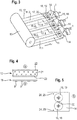
- Fig. 3 For the production of several hood half-shells 1, the cellulose-containing blank 10 is removed from a roll 13 in the form of a further flat material 12.
- the further flat material 12 is fed to an arrangement of three molding tools 14.
- the three molding tools 14 each have a shaping surface 15 for the lower part 2, a shaping surface 16 for the upper part 3 and a shaping surface 17 for the hinge 4.
- the shaping surfaces 15, 16 for the lower part 2 and the upper part 3 are each formed by a first cavity 18 and a second cavity 19.
- the shaping surface 17 for the hinge 4 is formed by a recess 20 connecting the cavities 18, 19 to one another at the edge.
- the printed flat material 11.1, 11.2 is fed in the form of several separate webs. These are taken from at least one roll and are already printed.
- each molding tool 14 Two different printed flat materials 11.1, 11.2 are fed to each molding tool 14, namely a printed flat material 11.1 for the lower part 2 and another printed flat material 11.2 for the upper part 3.
- the printed flat material 11.1 for the lower part is marked at intervals with the copyright notice 7 printed.
- the material for the upper part is printed with the image 8 and the logo 9 next to it at intervals.
- Fig. 4 the flat material 11 and the further flat material 12 is shown in an enlarged vertical section. Accordingly, in the case of the flat material 11, the printing 7, 8, 9 is assigned on the underside that faces the molding tool 14.
- the further flat material 12 consists of a central layer of cellulose 21 and tissue papers 22, 23 on the upper side and the lower side. During the production of the further flat material 12, the tissue papers 22, 23 are connected as an airlaid to the cellulose layer 21. They are carriers for the cotton wool-like pulp 21.
- each molding tool 14 has stationary register marks 24 and the printed flat material 11 has registration marks 25 printed thereon. These are made to coincide so that we can align the printed flat material 11 with its printing 7, 8, 9 in precise register with the shaping surfaces 15, 16.
- the two webs of printed flat material 11.1, 11.2 and the further flat material 12 are pressed into the cavities 18, 19 and against the shaping surfaces 15, 16 and the recess 20, e.g. by inserting punches from above.
- the stamp and / or the shaping surfaces 18, 19 and the recess 20 are heated and the layers bond with one another through the effect of pressure and temperature.
- the stamps are preferably also designed as punches and separate protruding edge material from the hood half-shells 1.
- the hood half-shells 1 with the punches can then be removed from the cavities 18, 19 and the recess 20 and stripped from them.
- the cavities 18, 19 for the formation of the lower part 2 and the upper part 3 are arranged next to one another perpendicular to the transport direction of the flat materials 11, 12. This is advantageous for the feeding of separate printed flat materials 11.1, 11.2 to lower part 2 and upper part 3.
- Fig. 6 it is basically also possible to arrange the cavities 18, 19 for the formation of the lower part 2 and the upper part 3 one behind the other in the transport direction of the flat materials 11, 12.
- the lower part 2 or the upper part 3 is provided with a printed flat material 11 or is the printed flat material 11 at the same time aligned on the shaping surfaces 15, 16 for the lower part 2 and the upper part 3.
Landscapes
- Making Paper Articles (AREA)
- Printing Methods (AREA)
Claims (15)
- Procédé de fabrication d'un objet tridimensionnel à base de cellulose comprenant les étapes suivantes :• une ébauche contenant de la cellulose est positionnée devant une surface de mise en forme d'un moule de formage définissant la forme de l'objet,• un matériau plat imprimé est positionné devant la surface de mise en forme du moule de formage et est aligné avec une impression sur la surface de mise en forme par un repérage précis et• l'ébauche et le matériau plat sont chauffés, plaqués contre la surface de mise en forme et formés pour générer un objet tridimensionnel.
- Procédé selon la revendication 1, dans lequel le matériau plat imprimé est un papier tissu et/ou dans lequel l'ébauche est constituée essentiellement ou complètement de fibres cellulosiques ou de fibres cellulosiques modifiées.
- Procédé selon la revendication 1 ou 2, dans lequel l'ébauche est un autre matériau plat.
- Procédé selon la revendication 3, dans lequel l'ébauche constituée d'un autre matériau plat présente une épaisseur à base de matériau plat sur une face extérieure plate ou sur deux faces extérieures plates, sachant que le matériau plat est de préférence un matériau plat imprimable sur la face extérieure de l'ébauche, mieux encore un papier tissu.
- Procédé selon l'une des revendications 1 à 4, dans lequel le matériau plat imprimé est appliqué en plus sur une face extérieure de l'ébauche lors du formage de l'objet.
- Procédé selon l'une des revendications 1 à 5, dans lequel une ébauche constituée d'un autre matériau plat, qui présente un matériau plat imprimable sur au moins une face extérieure plate, est imprimée sur le matériau plat imprimable et l'impression est alignée sur la surface de mise en forme par un repérage précis lors du positionnement de l'ébauche devant la surface de mise en forme.
- Procédé selon l'une des revendications 1 à 6, dans lequel le matériau plat imprimé est positionné sur la face de l'ébauche opposée au moule de formage ou sur la face de l'ébauche tournée vers le moule de formage et/ou dans lequel le matériau plat imprimé est positionné avec l'impression sur la face opposée à l'ébauche.
- Procédé selon l'une des revendications 1 à 7, dans lequel des marques de repérage sont imprimées sur le matériau plat, le moule de formage présente au moins une marque de repérage stationnaire et l'impression est alignée sur la surface de mise en forme par un repérage précis moyennant l'ajustement d'au moins une marque de repérage imprimée sur ladite marque de repérage stationnaire au moins.
- Procédé selon l'une des revendications 1 à 8, dans lequel une seule ébauche et des parties séparées les unes des autres du matériau plat sont positionnées en même temps devant les surfaces de mise en forme de plusieurs moules de formage, sachant que les parties séparées les unes des autres du matériau plat imprimé sont alignées respectivement isolément par un repérage précis sur la surface de mise en forme du moule de formage respectif, devant lequel elles sont positionnées.
- Procédé selon l'une des revendications 1 à 8, dans lequel une ébauche constituée d'un autre matériau plat, qui est reliée fixement à un matériau plat imprimable sur au moins une face extérieure, est imprimée sur le matériau plat imprimable le long de plusieurs rangées parallèles, est détachée entre les rangées imprimées et les parties séparées de l'autre matériau plat sont positionnées respectivement isolément devant différents moules de formage et alignées avec leurs impressions respectivement par un repérage précis sur la surface de mise en forme des moules de formage.
- Procédé selon l'une des revendications 1 à 10, dans lequel au moins un moule de formage pour former des objets avec plusieurs parties d'objet rattachées est utilisé et un matériau plat imprimé isolé, destiné uniquement à la liaison avec cette partie d'objet est positionné devant au moins une surface de mise en forme du moule de formage d'une seule des parties d'objet rattachées et est aligné avec son impression par un repérage précis sur la surface de mise en forme du moule de formage de la partie d'objet concernée.
- Procédé selon l'une des revendications 1 à 11, dans lequel le matériau plat imprimé est positionné devant la surface de mise en forme d'une partie d'objet du moule de formage et est aligné avec l'impression par un repérage précis sur la surface de mise en forme et un matériau plat formant une couche barrière est positionné devant la surface de mise en forme d'une autre partie d'objet et le matériau plat imprimé est relié fixement à ladite partie d'objet et la couche barrière est reliée fixement à l'autre partie d'objet lors du formage de l'objet tridimensionnel.
- Procédé selon l'une des revendications 1 à 12, dans lequel une pression est appliquée et de la chaleur est fournie lors du formage de l'objet tridimensionnel au moyen d'un poinçon chauffé ou dans lequel une pression est appliquée au moyen d'un moule de formage avec une membrane et de la chaleur est fournie par le biais de la surface de mise en forme du moule de formage, sachant que le matériau périphérique débordant est découpé de préférence lors du formage de l'objet tridimensionnel ou par la suite.
- Dispositif de fabrication d'un objet tridimensionnel d'après le procédé selon l'une des revendications 1 à 13, dans lequel un moule de formage présente au moins une marque de repérage stationnaire pour aligner au moins une marque de repérage imprimée d'une impression sur un matériau plat imprimé.
- Dispositif selon la revendication 14, qui présente au moins un capteur optique pour détecter au moins une marque de repérage imprimée, un appareil de commande électrique relié au capteur optique et un appareil d'alimentation motorisé acheminant le matériau plat imprimé jusqu'au moule de formage, dans lequel l'appareil de commande électronique est conçu de manière à détecter la position d'une marque de repérage imprimée et à diriger l'appareil d'alimentation en fonction de la position détectée de sorte que la marque de repérage imprimée est alignée sur la marque de repérage stationnaire, et/ou dans lequel l'appareil de commande électronique est relié à un appareil servant à exercer une pression sur l'ébauche et le matériau plat imprimé, et l'appareil de commande électronique est conçu de manière à diriger l'appareil servant à exercer une pression de sorte que celui-ci plaque l'ébauche et le matériau plat imprimé contre la surface de mise en forme du moule de formage lorsque la marque de repérage imprimée est alignée sur la marque de repérage stationnaire.
Priority Applications (2)
| Application Number | Priority Date | Filing Date | Title |
|---|---|---|---|
| EP18179933.9A EP3587665B1 (fr) | 2018-06-26 | 2018-06-26 | Procédé et dispositif de fabrication d'un objet tridimensionnel à base de cellulose |
| RU2019119079A RU2778308C2 (ru) | 2018-06-26 | 2019-06-19 | Способ и устройство для изготовления трехмерного изделия на основе целлюлозы |
Applications Claiming Priority (1)
| Application Number | Priority Date | Filing Date | Title |
|---|---|---|---|
| EP18179933.9A EP3587665B1 (fr) | 2018-06-26 | 2018-06-26 | Procédé et dispositif de fabrication d'un objet tridimensionnel à base de cellulose |
Publications (2)
| Publication Number | Publication Date |
|---|---|
| EP3587665A1 EP3587665A1 (fr) | 2020-01-01 |
| EP3587665B1 true EP3587665B1 (fr) | 2021-01-06 |
Family
ID=62791643
Family Applications (1)
| Application Number | Title | Priority Date | Filing Date |
|---|---|---|---|
| EP18179933.9A Active EP3587665B1 (fr) | 2018-06-26 | 2018-06-26 | Procédé et dispositif de fabrication d'un objet tridimensionnel à base de cellulose |
Country Status (1)
| Country | Link |
|---|---|
| EP (1) | EP3587665B1 (fr) |
Families Citing this family (1)
| Publication number | Priority date | Publication date | Assignee | Title |
|---|---|---|---|---|
| DE102023107364A1 (de) | 2023-03-23 | 2024-09-26 | IP Verpackungen GmbH | Verfahren und Vorrichtung zum Herstellen eines dreidimensionalen Zelluloseproduktes und dreidimensionales Zelluloseprodukt |
Family Cites Families (4)
| Publication number | Priority date | Publication date | Assignee | Title |
|---|---|---|---|---|
| US3058869A (en) * | 1956-12-20 | 1962-10-16 | Rockline Realty Corp | Pre-printed corrugated board fabrication and cut-off control method and apparatus |
| US3576711A (en) * | 1967-02-02 | 1971-04-27 | Abitibi Paper Co Ltd | Fibreboard including paper sheet with woodgrain line pattern and complementary, but non-registering embossed pattern |
| US8663419B2 (en) * | 2010-11-30 | 2014-03-04 | Ecologic | Manual container assembly and liner integration fixture for pulp-molded shell with polymer liner container systems |
| SE539948C2 (en) | 2016-03-18 | 2018-02-06 | The Core Company Ab | ISOSTATIC PRESSURE FORMING OF HEATED DRY CELLULOSE FIBERS |
-
2018
- 2018-06-26 EP EP18179933.9A patent/EP3587665B1/fr active Active
Non-Patent Citations (1)
| Title |
|---|
| None * |
Also Published As
| Publication number | Publication date |
|---|---|
| RU2019119079A (ru) | 2020-12-21 |
| EP3587665A1 (fr) | 2020-01-01 |
Similar Documents
| Publication | Publication Date | Title |
|---|---|---|
| DE3539573C2 (fr) | ||
| DE3008817C2 (fr) | ||
| WO2011000005A1 (fr) | Procédé de fabrication de platines estampées | |
| DE69920096T2 (de) | Verfahren zum Herstellen von Verpackungsmaterial mit Faltlinien | |
| DE102016106142A1 (de) | Packmittel umfassend Fasermaterial und Verfahren zu seiner Herstellung durch Kompressionsziehen | |
| EP3489005B1 (fr) | Outil de moulage et procédé de fabrication d'un emballage | |
| EP3587665B1 (fr) | Procédé et dispositif de fabrication d'un objet tridimensionnel à base de cellulose | |
| EP3792057A1 (fr) | Procédé de fabrication de produits au moins partiellement en forme de tige en papier, en carton ou en une autre matière contenant des fibres | |
| DE60029984T2 (de) | Verfahren zur herstellung eines verpackungsbehaelters mit einer oeffnungsvorrichtung | |
| WO2009143981A1 (fr) | Paire de rouleaux de gaufrage et rouleau de gaufrage pour produire par voie rotative un motif gaufré dans une feuille plate | |
| DE102011113401A1 (de) | Verfahren und Vorrichtung zum Herstellen von Zigaretten-Packungen | |
| DE102011120949A1 (de) | Verpackungsmaschine mit einem Mittel zur Befestigung einer Einlage an einem Strukturelement | |
| DE69425248T2 (de) | Mehrschichtiges Tissuepapier sowie dessen Herstellungsverfahren | |
| DE102007031001A1 (de) | Bogenrotationsdruckmaschine | |
| EP3331692B1 (fr) | Étiquette à colle humide pour contenants, outil d'estampage destiné à une étiquette à colle humide pour contenants et contenant ou bouteille comportant une telle étiquette à colle humide | |
| EP0596390A1 (fr) | Matrice pour la production de flans de boîtes en carton | |
| DE2728977C3 (de) | Verfahren zum Herstellen eines bahnförmigen Schichtmaterials, Vorrichtung zur Durchführung des Verfahrens und Verwendung des Schichtmaterials | |
| DE1786135B2 (de) | Verfahren zum herstellen von behaeltern | |
| DE202016102437U1 (de) | Banderole für Backwaren | |
| DE202023101892U1 (de) | Vorrichtung zum Herstellen eines dreidimensionalen Zelluloseproduktes und dreidimensionales Zelluloseprodukt | |
| EP1380409A2 (fr) | Bande d'étiquettes et procédé pour sa fabrication | |
| DE19840981A1 (de) | Verfahren und Vorrichtung zum Herstellen bedruckter und geprägter Teile | |
| DE102023107364A1 (de) | Verfahren und Vorrichtung zum Herstellen eines dreidimensionalen Zelluloseproduktes und dreidimensionales Zelluloseprodukt | |
| DE102022125393A1 (de) | Verpackung aus faserbasiertem Packmaterial | |
| DE4445245A1 (de) | Buchbindereierzeugnis |
Legal Events
| Date | Code | Title | Description |
|---|---|---|---|
| PUAI | Public reference made under article 153(3) epc to a published international application that has entered the european phase |
Free format text: ORIGINAL CODE: 0009012 |
|
| STAA | Information on the status of an ep patent application or granted ep patent |
Free format text: STATUS: THE APPLICATION HAS BEEN PUBLISHED |
|
| AK | Designated contracting states |
Kind code of ref document: A1 Designated state(s): AL AT BE BG CH CY CZ DE DK EE ES FI FR GB GR HR HU IE IS IT LI LT LU LV MC MK MT NL NO PL PT RO RS SE SI SK SM TR |
|
| AX | Request for extension of the european patent |
Extension state: BA ME |
|
| STAA | Information on the status of an ep patent application or granted ep patent |
Free format text: STATUS: REQUEST FOR EXAMINATION WAS MADE |
|
| 17P | Request for examination filed |
Effective date: 20200408 |
|
| RBV | Designated contracting states (corrected) |
Designated state(s): AL AT BE BG CH CY CZ DE DK EE ES FI FR GB GR HR HU IE IS IT LI LT LU LV MC MK MT NL NO PL PT RO RS SE SI SK SM TR |
|
| GRAP | Despatch of communication of intention to grant a patent |
Free format text: ORIGINAL CODE: EPIDOSNIGR1 |
|
| STAA | Information on the status of an ep patent application or granted ep patent |
Free format text: STATUS: GRANT OF PATENT IS INTENDED |
|
| RAP1 | Party data changed (applicant data changed or rights of an application transferred) |
Owner name: AR PACKAGING GMBH |
|
| INTG | Intention to grant announced |
Effective date: 20200819 |
|
| GRAS | Grant fee paid |
Free format text: ORIGINAL CODE: EPIDOSNIGR3 |
|
| GRAA | (expected) grant |
Free format text: ORIGINAL CODE: 0009210 |
|
| STAA | Information on the status of an ep patent application or granted ep patent |
Free format text: STATUS: THE PATENT HAS BEEN GRANTED |
|
| AK | Designated contracting states |
Kind code of ref document: B1 Designated state(s): AL AT BE BG CH CY CZ DE DK EE ES FI FR GB GR HR HU IE IS IT LI LT LU LV MC MK MT NL NO PL PT RO RS SE SI SK SM TR |
|
| REG | Reference to a national code |
Ref country code: GB Ref legal event code: FG4D Free format text: NOT ENGLISH |
|
| REG | Reference to a national code |
Ref country code: AT Ref legal event code: REF Ref document number: 1352496 Country of ref document: AT Kind code of ref document: T Effective date: 20210115 Ref country code: CH Ref legal event code: EP |
|
| REG | Reference to a national code |
Ref country code: DE Ref legal event code: R096 Ref document number: 502018003527 Country of ref document: DE |
|
| REG | Reference to a national code |
Ref country code: IE Ref legal event code: FG4D Free format text: LANGUAGE OF EP DOCUMENT: GERMAN |
|
| REG | Reference to a national code |
Ref country code: SE Ref legal event code: TRGR |
|
| REG | Reference to a national code |
Ref country code: NL Ref legal event code: MP Effective date: 20210106 |
|
| REG | Reference to a national code |
Ref country code: LT Ref legal event code: MG9D |
|
| PG25 | Lapsed in a contracting state [announced via postgrant information from national office to epo] |
Ref country code: LT Free format text: LAPSE BECAUSE OF FAILURE TO SUBMIT A TRANSLATION OF THE DESCRIPTION OR TO PAY THE FEE WITHIN THE PRESCRIBED TIME-LIMIT Effective date: 20210106 Ref country code: NO Free format text: LAPSE BECAUSE OF FAILURE TO SUBMIT A TRANSLATION OF THE DESCRIPTION OR TO PAY THE FEE WITHIN THE PRESCRIBED TIME-LIMIT Effective date: 20210406 Ref country code: PT Free format text: LAPSE BECAUSE OF FAILURE TO SUBMIT A TRANSLATION OF THE DESCRIPTION OR TO PAY THE FEE WITHIN THE PRESCRIBED TIME-LIMIT Effective date: 20210506 Ref country code: HR Free format text: LAPSE BECAUSE OF FAILURE TO SUBMIT A TRANSLATION OF THE DESCRIPTION OR TO PAY THE FEE WITHIN THE PRESCRIBED TIME-LIMIT Effective date: 20210106 Ref country code: GR Free format text: LAPSE BECAUSE OF FAILURE TO SUBMIT A TRANSLATION OF THE DESCRIPTION OR TO PAY THE FEE WITHIN THE PRESCRIBED TIME-LIMIT Effective date: 20210407 Ref country code: FI Free format text: LAPSE BECAUSE OF FAILURE TO SUBMIT A TRANSLATION OF THE DESCRIPTION OR TO PAY THE FEE WITHIN THE PRESCRIBED TIME-LIMIT Effective date: 20210106 Ref country code: BG Free format text: LAPSE BECAUSE OF FAILURE TO SUBMIT A TRANSLATION OF THE DESCRIPTION OR TO PAY THE FEE WITHIN THE PRESCRIBED TIME-LIMIT Effective date: 20210406 |
|
| PG25 | Lapsed in a contracting state [announced via postgrant information from national office to epo] |
Ref country code: LV Free format text: LAPSE BECAUSE OF FAILURE TO SUBMIT A TRANSLATION OF THE DESCRIPTION OR TO PAY THE FEE WITHIN THE PRESCRIBED TIME-LIMIT Effective date: 20210106 Ref country code: PL Free format text: LAPSE BECAUSE OF FAILURE TO SUBMIT A TRANSLATION OF THE DESCRIPTION OR TO PAY THE FEE WITHIN THE PRESCRIBED TIME-LIMIT Effective date: 20210106 Ref country code: RS Free format text: LAPSE BECAUSE OF FAILURE TO SUBMIT A TRANSLATION OF THE DESCRIPTION OR TO PAY THE FEE WITHIN THE PRESCRIBED TIME-LIMIT Effective date: 20210106 |
|
| PG25 | Lapsed in a contracting state [announced via postgrant information from national office to epo] |
Ref country code: IS Free format text: LAPSE BECAUSE OF FAILURE TO SUBMIT A TRANSLATION OF THE DESCRIPTION OR TO PAY THE FEE WITHIN THE PRESCRIBED TIME-LIMIT Effective date: 20210506 |
|
| REG | Reference to a national code |
Ref country code: DE Ref legal event code: R097 Ref document number: 502018003527 Country of ref document: DE |
|
| PG25 | Lapsed in a contracting state [announced via postgrant information from national office to epo] |
Ref country code: CZ Free format text: LAPSE BECAUSE OF FAILURE TO SUBMIT A TRANSLATION OF THE DESCRIPTION OR TO PAY THE FEE WITHIN THE PRESCRIBED TIME-LIMIT Effective date: 20210106 Ref country code: EE Free format text: LAPSE BECAUSE OF FAILURE TO SUBMIT A TRANSLATION OF THE DESCRIPTION OR TO PAY THE FEE WITHIN THE PRESCRIBED TIME-LIMIT Effective date: 20210106 Ref country code: SM Free format text: LAPSE BECAUSE OF FAILURE TO SUBMIT A TRANSLATION OF THE DESCRIPTION OR TO PAY THE FEE WITHIN THE PRESCRIBED TIME-LIMIT Effective date: 20210106 |
|
| PLBE | No opposition filed within time limit |
Free format text: ORIGINAL CODE: 0009261 |
|
| STAA | Information on the status of an ep patent application or granted ep patent |
Free format text: STATUS: NO OPPOSITION FILED WITHIN TIME LIMIT |
|
| PG25 | Lapsed in a contracting state [announced via postgrant information from national office to epo] |
Ref country code: RO Free format text: LAPSE BECAUSE OF FAILURE TO SUBMIT A TRANSLATION OF THE DESCRIPTION OR TO PAY THE FEE WITHIN THE PRESCRIBED TIME-LIMIT Effective date: 20210106 Ref country code: SK Free format text: LAPSE BECAUSE OF FAILURE TO SUBMIT A TRANSLATION OF THE DESCRIPTION OR TO PAY THE FEE WITHIN THE PRESCRIBED TIME-LIMIT Effective date: 20210106 Ref country code: DK Free format text: LAPSE BECAUSE OF FAILURE TO SUBMIT A TRANSLATION OF THE DESCRIPTION OR TO PAY THE FEE WITHIN THE PRESCRIBED TIME-LIMIT Effective date: 20210106 |
|
| 26N | No opposition filed |
Effective date: 20211007 |
|
| PG25 | Lapsed in a contracting state [announced via postgrant information from national office to epo] |
Ref country code: ES Free format text: LAPSE BECAUSE OF FAILURE TO SUBMIT A TRANSLATION OF THE DESCRIPTION OR TO PAY THE FEE WITHIN THE PRESCRIBED TIME-LIMIT Effective date: 20210106 Ref country code: AL Free format text: LAPSE BECAUSE OF FAILURE TO SUBMIT A TRANSLATION OF THE DESCRIPTION OR TO PAY THE FEE WITHIN THE PRESCRIBED TIME-LIMIT Effective date: 20210106 Ref country code: MC Free format text: LAPSE BECAUSE OF FAILURE TO SUBMIT A TRANSLATION OF THE DESCRIPTION OR TO PAY THE FEE WITHIN THE PRESCRIBED TIME-LIMIT Effective date: 20210106 |
|
| REG | Reference to a national code |
Ref country code: CH Ref legal event code: PL |
|
| PG25 | Lapsed in a contracting state [announced via postgrant information from national office to epo] |
Ref country code: SI Free format text: LAPSE BECAUSE OF FAILURE TO SUBMIT A TRANSLATION OF THE DESCRIPTION OR TO PAY THE FEE WITHIN THE PRESCRIBED TIME-LIMIT Effective date: 20210106 |
|
| REG | Reference to a national code |
Ref country code: BE Ref legal event code: MM Effective date: 20210630 |
|
| PG25 | Lapsed in a contracting state [announced via postgrant information from national office to epo] |
Ref country code: LU Free format text: LAPSE BECAUSE OF NON-PAYMENT OF DUE FEES Effective date: 20210626 |
|
| PG25 | Lapsed in a contracting state [announced via postgrant information from national office to epo] |
Ref country code: LI Free format text: LAPSE BECAUSE OF NON-PAYMENT OF DUE FEES Effective date: 20210630 Ref country code: IT Free format text: LAPSE BECAUSE OF FAILURE TO SUBMIT A TRANSLATION OF THE DESCRIPTION OR TO PAY THE FEE WITHIN THE PRESCRIBED TIME-LIMIT Effective date: 20210106 Ref country code: IE Free format text: LAPSE BECAUSE OF NON-PAYMENT OF DUE FEES Effective date: 20210626 Ref country code: CH Free format text: LAPSE BECAUSE OF NON-PAYMENT OF DUE FEES Effective date: 20210630 |
|
| PG25 | Lapsed in a contracting state [announced via postgrant information from national office to epo] |
Ref country code: IS Free format text: LAPSE BECAUSE OF FAILURE TO SUBMIT A TRANSLATION OF THE DESCRIPTION OR TO PAY THE FEE WITHIN THE PRESCRIBED TIME-LIMIT Effective date: 20210506 |
|
| PG25 | Lapsed in a contracting state [announced via postgrant information from national office to epo] |
Ref country code: BE Free format text: LAPSE BECAUSE OF NON-PAYMENT OF DUE FEES Effective date: 20210630 |
|
| PG25 | Lapsed in a contracting state [announced via postgrant information from national office to epo] |
Ref country code: NL Free format text: LAPSE BECAUSE OF NON-PAYMENT OF DUE FEES Effective date: 20210206 Ref country code: CY Free format text: LAPSE BECAUSE OF FAILURE TO SUBMIT A TRANSLATION OF THE DESCRIPTION OR TO PAY THE FEE WITHIN THE PRESCRIBED TIME-LIMIT Effective date: 20210106 |
|
| PG25 | Lapsed in a contracting state [announced via postgrant information from national office to epo] |
Ref country code: HU Free format text: LAPSE BECAUSE OF FAILURE TO SUBMIT A TRANSLATION OF THE DESCRIPTION OR TO PAY THE FEE WITHIN THE PRESCRIBED TIME-LIMIT; INVALID AB INITIO Effective date: 20180626 |
|
| PG25 | Lapsed in a contracting state [announced via postgrant information from national office to epo] |
Ref country code: MK Free format text: LAPSE BECAUSE OF FAILURE TO SUBMIT A TRANSLATION OF THE DESCRIPTION OR TO PAY THE FEE WITHIN THE PRESCRIBED TIME-LIMIT Effective date: 20210106 |
|
| PG25 | Lapsed in a contracting state [announced via postgrant information from national office to epo] |
Ref country code: TR Free format text: LAPSE BECAUSE OF FAILURE TO SUBMIT A TRANSLATION OF THE DESCRIPTION OR TO PAY THE FEE WITHIN THE PRESCRIBED TIME-LIMIT Effective date: 20210106 |
|
| PGFP | Annual fee paid to national office [announced via postgrant information from national office to epo] |
Ref country code: GB Payment date: 20240627 Year of fee payment: 7 |
|
| PGFP | Annual fee paid to national office [announced via postgrant information from national office to epo] |
Ref country code: DE Payment date: 20240627 Year of fee payment: 7 |
|
| PGFP | Annual fee paid to national office [announced via postgrant information from national office to epo] |
Ref country code: FR Payment date: 20240625 Year of fee payment: 7 |
|
| REG | Reference to a national code |
Ref country code: AT Ref legal event code: MM01 Ref document number: 1352496 Country of ref document: AT Kind code of ref document: T Effective date: 20230626 |
|
| PGFP | Annual fee paid to national office [announced via postgrant information from national office to epo] |
Ref country code: SE Payment date: 20240627 Year of fee payment: 7 |
|
| PG25 | Lapsed in a contracting state [announced via postgrant information from national office to epo] |
Ref country code: MT Free format text: LAPSE BECAUSE OF FAILURE TO SUBMIT A TRANSLATION OF THE DESCRIPTION OR TO PAY THE FEE WITHIN THE PRESCRIBED TIME-LIMIT Effective date: 20210106 |