EP3587196A1 - Gassackmodul für ein fahrzeuginsassen-rückhaltesystem sowie lenkradbaugruppe mit einem solchen gassackmodul - Google Patents
Gassackmodul für ein fahrzeuginsassen-rückhaltesystem sowie lenkradbaugruppe mit einem solchen gassackmodul Download PDFInfo
- Publication number
- EP3587196A1 EP3587196A1 EP19182976.1A EP19182976A EP3587196A1 EP 3587196 A1 EP3587196 A1 EP 3587196A1 EP 19182976 A EP19182976 A EP 19182976A EP 3587196 A1 EP3587196 A1 EP 3587196A1
- Authority
- EP
- European Patent Office
- Prior art keywords
- module
- latching
- housing
- steering wheel
- tongue
- Prior art date
- Legal status (The legal status is an assumption and is not a legal conclusion. Google has not performed a legal analysis and makes no representation as to the accuracy of the status listed.)
- Granted
Links
Images

Classifications
-
- B—PERFORMING OPERATIONS; TRANSPORTING
- B60—VEHICLES IN GENERAL
- B60R—VEHICLES, VEHICLE FITTINGS, OR VEHICLE PARTS, NOT OTHERWISE PROVIDED FOR
- B60R21/00—Arrangements or fittings on vehicles for protecting or preventing injuries to occupants or pedestrians in case of accidents or other traffic risks
- B60R21/02—Occupant safety arrangements or fittings, e.g. crash pads
- B60R21/16—Inflatable occupant restraints or confinements designed to inflate upon impact or impending impact, e.g. air bags
- B60R21/20—Arrangements for storing inflatable members in their non-use or deflated condition; Arrangement or mounting of air bag modules or components
- B60R21/203—Arrangements for storing inflatable members in their non-use or deflated condition; Arrangement or mounting of air bag modules or components in steering wheels or steering columns
- B60R21/2035—Arrangements for storing inflatable members in their non-use or deflated condition; Arrangement or mounting of air bag modules or components in steering wheels or steering columns using modules containing inflator, bag and cover attachable to the steering wheel as a complete sub-unit
Definitions
- the invention relates to an airbag module for a vehicle occupant restraint system with a module housing, which has a housing axis and a latching tongue for forming a latching connection with a module carrier, the latching tongue extending from the module housing in the axial direction to a free latching tongue end, and the latching tongue for Forming the latching connection in a transverse to the housing axis deformation direction is elastically deformable.
- the invention also includes a steering wheel assembly with such an airbag module.
- elastic latching tongues can be provided on the module side, which protrude from the module housing and protrude towards the steering wheel, where, after elastic deformation, they snap into rigid latching hooks provided on the steering wheel, for example.
- the latching tongues and latching hooks must work together in a technically perfect manner when latching and, in particular, must not be damaged in order to reliably prevent an undesired loosening of the latching connection when the gas bag module is activated and to ensure transmission of high module forces.
- the elastic latching tongues protruding from the module housing can be overstretched in individual cases, for example if a gas bag module falls down. Even in the event of improper disassembly of the gas bag module from the module carrier, unintentional overstretching can occur, for example if the elastic locking tongues are excessively deformed by a tool for releasing the locking connection.
- Overloading can reduce the load-bearing capacity and / or the resilience of the elastic locking tongues, which has a negative effect on the load-bearing capacity of the locking connection. Furthermore, such damage to the locking tongues resulting from overextension is not readily recognizable to a fitter.
- the object of the invention is to provide an airbag module which can be locked with a module carrier and a steering wheel assembly with such an airbag module and a module carrier which can be locked therewith, wherein a predetermined load capacity of the locking connection is to be achieved particularly reliably.
- this object is achieved by a gas bag module of the type mentioned at the outset, in which the module housing has a stop element for limiting deformation of the latching tongues.
- This stop element which is arranged adjacent to the latching tongue, prevents excessive deformation of the latching tongue with little effort, so that the resilience of the latching connection cannot be impaired by overstretching the latching tongue.
- the stop element viewed in the direction of deformation, is preferably arranged adjacent to the latching tongue and spaced from the free latching tongue end.
- the module housing has a module base on the module carrier side, which extends essentially perpendicular to the housing axis, the latching tongue being arranged on the module base.
- the module housing can be a plastic housing, the latching tongue preferably being formed in one piece with the module housing and particularly preferably being molded in one piece on the module base of the module housing.
- the stop element can also be integrally formed on the module base, so that the module base of the plastic housing, including the latching tongue and stop element, can be manufactured as an injection molded part with little effort.
- the stop element extends from the module housing in the axial direction to a free stop end, the stop end having a contact section for the latching tongue.
- an axial dimension of the latching tongue is larger than an axial dimension of the stop element. Consequently, a contact section of the latching tongue for the stop element lies between the free latching tongue end and the module base.
- the invention further relates to a steering wheel assembly for a motor vehicle, with an airbag module described above and a steering wheel which has a module carrier for the airbag module and is rotatable about a steering wheel axis, the module carrier having a latching element for forming a latching connection with the latching tongue of the module housing.
- the steering wheel axis preferably extends parallel to the housing axis of the gas bag module or is even identical to it in some embodiments.
- the module carrier can be a steering wheel skeleton or a mounting plate of the steering wheel that is firmly connected to the steering wheel skeleton.
- the latching element of the module carrier is preferably an essentially rigid latching hook, which is in particular integrally formed on the steering wheel skeleton or on the mounting plate.
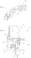
- the Figure 1 shows an airbag module 10 for a vehicle occupant restraint system, with a module housing 12, which has a housing axis A and a latching tongue 14 for forming a latching connection with a module carrier 16 (see Figures 3 and 4 ), the locking tongue 14 extending from the module housing 12 in the axial direction to a free locking tongue end 18.
- the module housing 12 is a plastic housing and has a module base 20 on the module carrier side, which extends essentially perpendicular to the housing axis A, the latching tongue 14 being arranged on the module base 20.
- FIG. 2 An in Figure 2 The detailed section of the gas bag module 10 shown in the area of the latching tongue 14 clarifies that the latching tongue 14 is embodied here in one piece with the module housing 12 and is specifically formed on the module base 20 thereof.
- the latching tongue 14 is elastically deformable to form the latching connection with the module carrier 16 in a deformation direction 22 running transversely to the housing axis A, the module housing 12 having a stop element 24 for limiting a latching tongue deformation.
- the stop element 24 is arranged adjacent to the latching tongue 14 and spaced from the free latching tongue end 18.
- the stop element 24 is essentially rigid in the direction of deformation 22 and extends from the module housing 12 in the direction of the housing axis A to a free stop end 26, the stop end 26 forming a contact section 28 for the latching tongue 14.
- the Figure 3 shows a section of a module carrier 16 on which the gas bag module 10 described above can be locked.
- the module carrier 16 is a steering wheel skeleton of a steering wheel 30 and has a latching element 32 for forming a latching connection with the latching tongue 14 of the gas bag module 10.
- the locking element 32 is an essentially rigid locking hook and in particular is integrally formed on the module carrier 16.
- the gas bag module 10 does not lock directly on the steering wheel skeleton, but on a mounting plate of the steering wheel 30 which is firmly connected to the steering wheel skeleton and which then forms the module carrier 16.
- the airbag module 10 is a driver's front airbag module, but could alternatively also be another airbag module that can be used anywhere in the motor vehicle and has elastic locking tongues for locking with a suitable module carrier.
- the steering wheel 30 with the module carrier 16 designed as a steering wheel skeleton or mounting plate can be rotated about a steering wheel axis.
- the gas bag module 10 described above forms, together with the steering wheel 30, a steering wheel assembly 34 for a motor vehicle, the housing axis A of the gas bag module 10 running parallel to the steering wheel axis or even being identical to it.
- the Figure 4 shows the steering wheel assembly 34 in the area of the latching connection between the airbag module 10 and the module carrier 16, the latching tongue 14 of the gasbag module 10 being in latching engagement with the latching element 32 of the module carrier 16.
- the elastic latching tongue 14 is acted upon by a bevel 36 on the module side of the latching element 32 or a tool and then assumes a position deflected in the direction of deformation 22, which is shown in FIG Figure 4 is indicated by dashed lines.
- the stop element 24 is arranged and shaped geometrically in such a way that it permits a deformation of the latching tongue 14 necessary for the assembly and disassembly of the gas bag module 10, but in the event of a larger deformation beyond that it forms an essentially rigid stop on which the latching tongue 14 is supported , so that an overextension of the locking tongue 14 is reliably prevented.
Landscapes
- Engineering & Computer Science (AREA)
- Mechanical Engineering (AREA)
- Air Bags (AREA)
Abstract
Description
- Die Erfindung betrifft ein Gassackmodul für ein Fahrzeuginsassen-Rückhaltesystem mit einem Modulgehäuse, das eine Gehäuseachse und eine Rastzunge zur Ausbildung einer Rastverbindung mit einem Modulträger aufweist, wobei sich die Rastzunge ausgehend vom Modulgehäuse in axialer Richtung zu einem freien Rastzungenende erstreckt, und wobei die Rastzunge zur Ausbildung der Rastverbindung in einer quer zur Gehäuseachse verlaufenden Verformungsrichtung elastisch verformbar ist. Darüber hinaus umfasst die Erfindung auch eine Lenkradbaugruppe mit einem solchen Gassackmodul.
- Es ist aus dem Stand der Technik allgemein bekannt und im Fahrzeugbau mittlerweile auch weit verbreitet, Gassackmodule über eine Rastverbindung an einem Modulträger wie etwa einem Lenkrad zu befestigen. So lässt sich zum Beispiel nach einer Montage des Lenkrads im Fahrzeug ein fahrerseitiges Frontgassackmodul mit geringem Montageaufwand einfach aufstecken und zuverlässig am Lenkrad verrasten.
- Zum Ausbilden der Rastverbindung können modulseitig elastische Rastzungen vorgesehen sein, welche vom Modulgehäuse abstehen und in Richtung zum Lenkrad ragen, wo sie nach einer elastischen Verformung beispielsweise in starre, am Lenkrad vorgesehene Rasthaken einschnappen.
- Die Rastzungen und Rasthaken müssen beim Verrasten technisch einwandfrei zusammenwirken und dürfen insbesondere nicht beschädigt sein, um bei einer Aktivierung des Gassackmoduls ein unerwünschtes Lösen der Rastverbindung zuverlässig zu verhindern und eine Übertragung hoher Modulkräfte zu gewährleisten.
- Es hat sich allerdings herausgestellt, dass bei der Verarbeitung oder beim Transport der Gassackmodule die am Modulgehäuse vorstehenden, elastischen Rastzungen in Einzelfällen überdehnt werden können, beispielsweise wenn ein Gassackmodul herunterfällt. Auch im Falle einer unsachgemäßen Demontage des Gassackmoduls vom Modulträger kann es zu einer unbeabsichtigten Überdehnung kommen, beispielsweise wenn die elastischen Rastzungen durch ein Werkzeug zum Lösen der Rastverbindung übermäßig verformt werden.
- Durch eine Überdehnung kann sich die Tragfähigkeit und/oder die Spannkraft der elastischen Rastzungen verringern, was sich negativ auf die Belastbarkeit der Rastverbindung auswirkt. Ferner ist eine solche, aus Überdehnung resultierende Beschädigung der Rastzungen für einen Monteur visuell nicht ohne weiteres erkennbar.
- Aufgabe der Erfindung ist es, ein mit einem Modulträger verrastbares Gassackmodul sowie eine Lenkradbaugruppe mit einem solchen Gassackmodul und einem damit verrastbaren Modulträger zu schaffen, wobei eine vorbestimmte Belastbarkeit der Rastverbindung besonders zuverlässig erreicht werden soll.
- Erfindungsgemäß wird diese Aufgabe gelöst durch ein Gassackmodul der eingangs genannten Art, bei dem das Modulgehäuse ein Anschlagelement zur Begrenzung einer Rastzungenverformung aufweist. Dieses benachbart zur Rastzunge angeordnete Anschlagelement verhindert mit geringem Aufwand eine übermäßige Verformung der Rastzunge, sodass die Belastbarkeit der Rastverbindung nicht durch Überdehnung der Rastzunge beeinträchtigt werden kann.
- Vorzugsweise ist das Anschlagelement, in Verformungsrichtung gesehen, benachbart zur Rastzunge angeordnet und vom freien Rastzungenende beabstandet.
- In einer Ausführungsform des Gassackmoduls weist das Modulgehäuse einen modulträgerseitigen Modulboden auf, der sich im Wesentlichen senkrecht zur Gehäuseachse erstreckt, wobei die Rastzunge am Modulboden angeordnet ist.
- Das Modulgehäuse kann ein Kunststoffgehäuse sein, wobei die Rastzunge vorzugsweise einstückig mit dem Modulgehäuse ausgebildet und besonders bevorzugt einstückig an den Modulboden des Modulgehäuses angeformt ist. Ferner kann auch das Anschlagelement einstückig an den Modulboden angeformt sein, sodass sich der Modulboden des Kunststoffgehäuses einschließlich Rastzunge und Anschlagelement mit geringem Aufwand als Spritzgussteil fertigen lässt.
- Gemäß einer weiteren Ausführungsform des Gassackmoduls erstreckt sich das Anschlagelement ausgehend vom Modulgehäuse in axialer Richtung bis zu einem freien Anschlagende, wobei das Anschlagende einen Kontaktabschnitt für die Rastzunge aufweist.
- Insbesondere ist eine axiale Abmessung der Rastzunge größer als eine axiale Abmessung des Anschlagelements. Folglich liegt ein Kontaktabschnitt der Rastzunge für das Anschlagelement zwischen dem freien Rastzungenende und dem Modulboden.
- Die Erfindung betrifft ferner eine Lenkradbaugruppe für ein Kraftfahrzeug, mit einem oben beschriebenen Gassackmodul sowie einem Lenkrad, das einen Modulträger für das Gassackmodul aufweist und um eine Lenkradachse drehbar ist, wobei der Modulträger ein Rastelement zur Ausbildung einer Rastverbindung mit der Rastzunge des Modulgehäuses aufweist. Die Lenkradachse erstreckt sich dabei vorzugsweise parallel zur Gehäuseachse des Gassackmoduls oder ist in einigen Ausführungsformen sogar mit dieser identisch.
- Der Modulträger kann ein Lenkradskelett oder eine fest mit dem Lenkradskelett verbundene Montageplatte des Lenkrads sein.
- Das Rastelement des Modulträgers ist bevorzugt ein im Wesentlichen starrer Rasthaken, der insbesondere einstückig am Lenkradskelett oder an der Montageplatte angeformt ist.
- Weitere Merkmale und Vorteile der Erfindung ergeben sich aus der nachfolgenden Beschreibung einer bevorzugten Ausführungsform unter Bezugnahme auf die Zeichnungen. In diesen zeigt:
-
Figur 1 eine Seitenansicht eines Modulgehäuses eines erfindungsgemäßen Gassackmoduls; -
Figur 2 eine perspektivische Ansicht des Modulgehäuses gemäßFigur 1 im Bereich einer Rastzunge und eines Anschlagelements; -
Figur 3 eine perspektivische Ansicht eines mit dem Modulgehäuse gemäßFigur 1 verrastbaren Modulträgers im Bereich eines Rastelements; und -
Figur 4 eine Schnittansicht einer erfindungsgemäßen Lenkradbaugruppe im Bereich der Rastverbindung zwischen Gassackmodul und Modulträger. - Die
Figur 1 zeigt ein Gassackmodul 10 für ein Fahrzeuginsassen-Rückhaltesystem, mit einem Modulgehäuse 12, welches eine Gehäuseachse A und eine Rastzunge 14 zur Ausbildung einer Rastverbindung mit einem Modulträger 16 (sieheFiguren 3 und 4 ) aufweist, wobei sich die Rastzunge 14 ausgehend vom Modulgehäuse 12 in axialer Richtung zu einem freien Rastzungenende 18 erstreckt. - Das Modulgehäuse 12 ist im vorliegenden Ausführungsbeispiel ein Kunststoffgehäuse und weist einen modulträgerseitigen Modulboden 20 auf, der sich im Wesentlichen senkrecht zur Gehäuseachse A erstreckt, wobei die Rastzunge 14 am Modulboden 20 angeordnet ist.
- Ein in
Figur 2 dargestellter Detailausschnitt des Gassackmoduls 10 im Bereich der Rastzunge 14 verdeutlicht, dass die Rastzunge 14 hier einstückig mit dem Modulgehäuse 12 ausgeführt und konkret an dessen Modulboden 20 angeformt ist. - Die Rastzunge 14 ist zur Ausbildung der Rastverbindung mit dem Modulträger 16 in einer quer zur Gehäuseachse A verlaufenden Verformungsrichtung 22 elastisch verformbar, wobei das Modulgehäuse 12 ein Anschlagelement 24 zur Begrenzung einer Rastzungenverformung aufweist.
- In Verformungsrichtung 22 gesehen ist das Anschlagelement 24 benachbart zur Rastzunge 14 angeordnet und vom freien Rastzungenende 18 beabstandet. Das Anschlagelement 24 ist in Verformungsrichtung 22 im Wesentlichen starr ausgebildet und erstreckt sich ausgehend vom Modulgehäuse 12 in Richtung der Gehäuseachse A zu einem freien Anschlagende 26, wobei das Anschlagende 26 einen Kontaktabschnitt 28 für die Rastzunge 14 bildet.
- Gemäß
Figur 2 ist das Anschlagelement 24, analog zur Rastzunge 14, einstückig mit dem Modulgehäuse 12 ausgebildet und konkret an dessen Modulboden 20 angeformt. - Die
Figur 3 zeigt ausschnittsweise einen Modulträger 16, an dem das oben beschriebene Gassackmodul 10 verrastet werden kann. - Der Modulträger 16 ist im dargestellten Ausführungsbeispiel ein Lenkradskelett eines Lenkrads 30 und weist ein Rastelement 32 zur Ausbildung einer Rastverbindung mit der Rastzunge 14 des Gassackmoduls 10 auf. Das Rastelement 32 ist dabei ein im Wesentlichen starrer Rasthaken und insbesondere einstückig am Modulträger 16 angeformt.
- In einer alternativen Ausführungsvariante verrastet das Gassackmodul 10 nicht unmittelbar am Lenkradskelett, sondern an einer fest mit dem Lenkradskelett verbundenen Montageplatte des Lenkrads 30, welche dann den Modulträger 16 bildet.
- Das Gassackmodul 10 ist in diesem Fall ein fahrerseitiges Frontgassackmodul, könnte jedoch alternativ auch ein anderes, an beliebiger Stelle im Kraftfahrzeug einsetzbares Gassackmodul sein, welches elastische Rastzungen zur Verrastung mit einem geeigneten Modulträger aufweist.
- Das Lenkrad 30 mit dem als Lenkradskelett oder Montageplatte ausgebildeten Modulträger 16 ist um eine Lenkradachse drehbar. Nach einer Verrastung mit dem Modulträger 16 bildet das oben beschriebene Gassackmodul 10 zusammen mit dem Lenkrad 30 eine Lenkradbaugruppe 34 für ein Kraftfahrzeug, wobei die Gehäuseachse A des Gassackmoduls 10 parallel zur Lenkradachse verläuft oder sogar mit dieser identisch ist.
- Die
Figur 4 zeigt die Lenkradbaugruppe 34 im Bereich der Rastverbindung zwischen Gassackmodul 10 und Modulträger 16, wobei sich die Rastzunge 14 des Gassackmoduls 10 in Rasteingriff mit dem Rastelement 32 des Modulträgers 16 befindet. Beim Herstellen und Lösen der Rastverbindung wird die elastische Rastzunge 14 von einer modulseitigen Schräge 36 des Rastelements 32 bzw. einem Werkzeug beaufschlagt und nimmt dann eine in Verformungsrichtung 22 ausgelenkte Position ein, die inFigur 4 gestrichelt angedeutet ist. - Das Anschlagelement 24 ist dabei geometrisch so angeordnet und geformt, dass es eine für die Montage und Demontage des Gassackmoduls 10 notwendige Verformung der Rastzunge 14 erlaubt, jedoch bei einer darüberhinausgehenden, größeren Verformung einen im Wesentlichen starren Anschlag bildet, an dem sich die Rastzunge 14 abstützt, sodass eine Überdehnung der Rastzunge 14 zuverlässig verhindert wird.
- Anhand der
Figur 4 wird deutlich, dass eine axiale Abmessung s1 der Rastzunge 14 größer ist als eine axiale Abmessung s2 des Anschlagelements 24. Folglich liegt ein Kontaktabschnitt 38 der Rastzunge 14 für das Anschlagelement 24 zwischen dem freien Rastzungenende 18 und dem Modulboden 20. Das Anschlagelement 24 kann auf diese Weise zuverlässig eine Verformung der Rastzunge 14 begrenzen, ohne die Montage des Gassackmoduls 10 am Modulträger 16 zu behindern.
Claims (9)
- Gassackmodul für ein Fahrzeuginsassen-Rückhaltesystem, mit
einem Modulgehäuse (12), das eine Gehäuseachse (A) und eine Rastzunge (14) zur Ausbildung einer Rastverbindung mit einem Modulträger (16) aufweist,
wobei sich die Rastzunge (14) ausgehend vom Modulgehäuse (12) in Richtung der Gehäuseachse (A) zu einem freien Rastzungenende (18) erstreckt, und
wobei die Rastzunge (14) zur Ausbildung der Rastverbindung in einer quer zur Gehäuseachse (A) verlaufenden Verformungsrichtung (22) elastisch verformbar ist,
dadurch gekennzeichnet, dass das Modulgehäuse (12) ein Anschlagelement (24) zur Begrenzung einer Rastzungenverformung aufweist. - Gassackmodul nach Anspruch 1, dadurch gekennzeichnet, dass das Anschlagelement (24), in Verformungsrichtung (22) gesehen, benachbart zur Rastzunge (14) angeordnet und vom freien Rastzungenende (18) beabstandet ist.
- Gassackmodul nach Anspruch 1 oder 2, dadurch gekennzeichnet, dass das Modulgehäuse (12) einen modulträgerseitigen Modulboden (20) aufweist, der sich im Wesentlichen senkrecht zur Gehäuseachse (A) erstreckt, wobei die Rastzunge (14) am Modulboden (20) angeordnet ist.
- Gassackmodul nach wenigstens einem der vorhergehenden Ansprüche, dadurch gekennzeichnet, dass das Modulgehäuse (12) ein Kunststoffgehäuse ist, insbesondere wobei die Rastzunge (14) einstückig mit dem Modulgehäuse (12) ausgebildet ist.
- Gassackmodul nach wenigstens einem der vorhergehenden Ansprüche, dadurch gekennzeichnet, dass sich das Anschlagelement (24) ausgehend vom Modulgehäuse (12) in Richtung der Gehäuseachse (A) zu einem freien Anschlagende (26) erstreckt, wobei das Anschlagende (26) einen Kontaktabschnitt (28) für die Rastzunge (14) aufweist.
- Gassackmodul nach wenigstens einem der vorhergehenden Ansprüche, dadurch gekennzeichnet, dass eine axiale Abmessung (si) der Rastzunge (14) größer ist als eine axiale Abmessung (s2) des Anschlagelements (24).
- Lenkradbaugruppe für ein Kraftfahrzeug, mit
einem Gassackmodul (10) nach einem der vorhergehenden Ansprüche sowie
einem Lenkrad (30), das einen Modulträger (16) für das Gassackmodul (10) aufweist,
wobei der Modulträger (16) ein Rastelement (32) zur Ausbildung einer Rastverbindung mit der Rastzunge (14) des Modulgehäuses (12) aufweist. - Lenkradbaugruppe nach Anspruch 7, dadurch gekennzeichnet, dass der Modulträger (16) ein Lenkradskelett oder eine fest mit dem Lenkradskelett verbundene Montageplatte des Lenkrads (30) ist.
- Lenkradbaugruppe nach Anspruch 7 oder 8, dadurch gekennzeichnet, dass das Rastelement (32) ein im Wesentlichen starrer Rasthaken ist.
Applications Claiming Priority (1)
| Application Number | Priority Date | Filing Date | Title |
|---|---|---|---|
| DE202018103719.6U DE202018103719U1 (de) | 2018-06-29 | 2018-06-29 | Gassackmodul für ein Fahrzeuginsassen-Rückhaltesystem sowie Lenkradbaugruppe mir einem solchen Gassackmodul |
Publications (2)
| Publication Number | Publication Date |
|---|---|
| EP3587196A1 true EP3587196A1 (de) | 2020-01-01 |
| EP3587196B1 EP3587196B1 (de) | 2020-12-30 |
Family
ID=67105927
Family Applications (1)
| Application Number | Title | Priority Date | Filing Date |
|---|---|---|---|
| EP19182976.1A Active EP3587196B1 (de) | 2018-06-29 | 2019-06-27 | Gassackmodul für ein fahrzeuginsassen-rückhaltesystem sowie lenkradbaugruppe mit einem solchen gassackmodul |
Country Status (2)
| Country | Link |
|---|---|
| EP (1) | EP3587196B1 (de) |
| DE (1) | DE202018103719U1 (de) |
Cited By (3)
| Publication number | Priority date | Publication date | Assignee | Title |
|---|---|---|---|---|
| WO2024046961A1 (en) * | 2022-08-31 | 2024-03-07 | Autoliv Development Ab | Steering wheel with an airbag module |
| WO2024046944A1 (en) * | 2022-08-31 | 2024-03-07 | Autoliv Development Ab | Steering wheel with an airbag module |
| WO2024046957A1 (en) * | 2022-08-31 | 2024-03-07 | Autoliv Development Ab | Steering wheel with an airbag module |
Families Citing this family (1)
| Publication number | Priority date | Publication date | Assignee | Title |
|---|---|---|---|---|
| DE102020204324A1 (de) * | 2020-04-02 | 2021-10-07 | Psa Automobiles Sa | Festlegevorrichtung zum aneinander Festlegen zweier Bauteile sowie Kraftfahrzeug mit einer derartigen Festlegevorrichtung |
Citations (2)
| Publication number | Priority date | Publication date | Assignee | Title |
|---|---|---|---|---|
| US20050200104A1 (en) * | 2002-02-08 | 2005-09-15 | Xiaoping Xu | Switch assembly for an airbag module attachment |
| US20110248481A1 (en) * | 2008-12-02 | 2011-10-13 | Ichiro Amamori | Driver-airbag-apparatus-attaching structure and steering wheel |
Family Cites Families (2)
| Publication number | Priority date | Publication date | Assignee | Title |
|---|---|---|---|---|
| DE29920025U1 (de) * | 1999-11-15 | 2000-03-30 | TRW Automotive Safety Systems GmbH & Co. KG, 63743 Aschaffenburg | Vorrichtung zur Befestigung eines Gassackmoduls an einem Lenkrad |
| DE10307975A1 (de) * | 2003-02-24 | 2004-09-02 | Behr Gmbh & Co. Kg | Halteclip |
-
2018
- 2018-06-29 DE DE202018103719.6U patent/DE202018103719U1/de active Active
-
2019
- 2019-06-27 EP EP19182976.1A patent/EP3587196B1/de active Active
Patent Citations (2)
| Publication number | Priority date | Publication date | Assignee | Title |
|---|---|---|---|---|
| US20050200104A1 (en) * | 2002-02-08 | 2005-09-15 | Xiaoping Xu | Switch assembly for an airbag module attachment |
| US20110248481A1 (en) * | 2008-12-02 | 2011-10-13 | Ichiro Amamori | Driver-airbag-apparatus-attaching structure and steering wheel |
Non-Patent Citations (1)
| Title |
|---|
| ANONYMOUS: "Snap-in air bag module", RESEARCH DISCLOSURE, KENNETH MASON PUBLICATIONS, HAMPSHIRE, UK, GB, vol. 432, no. 30, 1 April 2000 (2000-04-01), XP007125885, ISSN: 0374-4353 * |
Cited By (3)
| Publication number | Priority date | Publication date | Assignee | Title |
|---|---|---|---|---|
| WO2024046961A1 (en) * | 2022-08-31 | 2024-03-07 | Autoliv Development Ab | Steering wheel with an airbag module |
| WO2024046944A1 (en) * | 2022-08-31 | 2024-03-07 | Autoliv Development Ab | Steering wheel with an airbag module |
| WO2024046957A1 (en) * | 2022-08-31 | 2024-03-07 | Autoliv Development Ab | Steering wheel with an airbag module |
Also Published As
| Publication number | Publication date |
|---|---|
| EP3587196B1 (de) | 2020-12-30 |
| DE202018103719U1 (de) | 2019-10-09 |
Similar Documents
| Publication | Publication Date | Title |
|---|---|---|
| EP3587196B1 (de) | Gassackmodul für ein fahrzeuginsassen-rückhaltesystem sowie lenkradbaugruppe mit einem solchen gassackmodul | |
| EP3303851B1 (de) | Vorrichtung zum halten eines bauteils | |
| DE102016100546A1 (de) | Blechmutter | |
| DE102017209492A1 (de) | Halterung zur Befestigung eines Sensors, insbesondere Radarsensors, an einem Fahrzeug und ein System aus einer Halterung und dem Sensor | |
| EP2508407B1 (de) | Gerüst, insbesondere für elektrische Einrichtungen in einem Schienenfahrzeug, und Verfahren zur Herstellung des Gerüsts | |
| DE102012003617A1 (de) | Gehäuse für ein Steuergerät | |
| DE102018217800B4 (de) | Adapter für einen Haltegriff im Innenraum eines Kraftfahrzeugs | |
| WO2016087141A1 (de) | Vorrichtung zum halten einer systemkomponente an einem anschlussteil eines fahrzeugs | |
| DE102018100555A1 (de) | Bodenbaugruppe eines Kraftfahrzeugs | |
| EP2566729A1 (de) | Wischermotor mit entkopplungselement und entkopplungselement | |
| DE202017105243U1 (de) | W-förmige, geflügelte Federklammer mit mindestens einem verstärkendem Versteifungsblech | |
| DE102016212058B4 (de) | Bauteilverbindung | |
| WO2017037077A1 (de) | Schutzelement für einen fahrzeugsitz, fahrzeugsitz | |
| DE202009012430U1 (de) | Grundträger | |
| DE112019003974T5 (de) | Schnappverbinder zur befestigung einer abdeckung und abdeckung | |
| DE102008031880B4 (de) | Befestigungselement für das Spannband einer Seitenairbaganordnung | |
| EP1375275B1 (de) | Getriebe-Antriebseinheit mit Rastelement | |
| DE102016005207B4 (de) | Haltevorrichtung für einen Spiegel eines Kraftfahrzeugs und zugehöriges Kraftfahrzeug | |
| DE102019000154A1 (de) | Anordnung eines Schutzelements an einer Hochvolt-Batterie für ein Kraftfahrzeug sowie Verfahren zum Befestigen eines solchen Schutzelements an einer Hochvolt-Batterie für ein Kraftfahrzeug | |
| DE202017106354U1 (de) | Haltevorrichtung für elektronische Geräte | |
| DE102009051531B4 (de) | Befestigungssystem | |
| AT505005B1 (de) | Anordnung zum verbinden von bauteilen | |
| DE102008044027B4 (de) | Mechanisches Befestigungssystem sowie Verfahren zur Befestigung eines Bauteiles an einem Festkörper | |
| DE102017006837A1 (de) | Befestigungsanordnung für eine Radhaus-Auskleidung einer Kraftfahrzeugkarosserie | |
| DE102005049140A1 (de) | Vorrichtung zur Befestigung eines Sensors |
Legal Events
| Date | Code | Title | Description |
|---|---|---|---|
| PUAI | Public reference made under article 153(3) epc to a published international application that has entered the european phase |
Free format text: ORIGINAL CODE: 0009012 |
|
| STAA | Information on the status of an ep patent application or granted ep patent |
Free format text: STATUS: THE APPLICATION HAS BEEN PUBLISHED |
|
| AK | Designated contracting states |
Kind code of ref document: A1 Designated state(s): AL AT BE BG CH CY CZ DE DK EE ES FI FR GB GR HR HU IE IS IT LI LT LU LV MC MK MT NL NO PL PT RO RS SE SI SK SM TR |
|
| AX | Request for extension of the european patent |
Extension state: BA ME |
|
| STAA | Information on the status of an ep patent application or granted ep patent |
Free format text: STATUS: REQUEST FOR EXAMINATION WAS MADE |
|
| 17P | Request for examination filed |
Effective date: 20200701 |
|
| RBV | Designated contracting states (corrected) |
Designated state(s): AL AT BE BG CH CY CZ DE DK EE ES FI FR GB GR HR HU IE IS IT LI LT LU LV MC MK MT NL NO PL PT RO RS SE SI SK SM TR |
|
| GRAP | Despatch of communication of intention to grant a patent |
Free format text: ORIGINAL CODE: EPIDOSNIGR1 |
|
| STAA | Information on the status of an ep patent application or granted ep patent |
Free format text: STATUS: GRANT OF PATENT IS INTENDED |
|
| RIC1 | Information provided on ipc code assigned before grant |
Ipc: B60R 21/203 20060101AFI20200722BHEP |
|
| INTG | Intention to grant announced |
Effective date: 20200817 |
|
| GRAS | Grant fee paid |
Free format text: ORIGINAL CODE: EPIDOSNIGR3 |
|
| GRAA | (expected) grant |
Free format text: ORIGINAL CODE: 0009210 |
|
| STAA | Information on the status of an ep patent application or granted ep patent |
Free format text: STATUS: THE PATENT HAS BEEN GRANTED |
|
| AK | Designated contracting states |
Kind code of ref document: B1 Designated state(s): AL AT BE BG CH CY CZ DE DK EE ES FI FR GB GR HR HU IE IS IT LI LT LU LV MC MK MT NL NO PL PT RO RS SE SI SK SM TR |
|
| REG | Reference to a national code |
Ref country code: GB Ref legal event code: FG4D Free format text: NOT ENGLISH |
|
| REG | Reference to a national code |
Ref country code: DE Ref legal event code: R096 Ref document number: 502019000605 Country of ref document: DE |
|
| REG | Reference to a national code |
Ref country code: AT Ref legal event code: REF Ref document number: 1349630 Country of ref document: AT Kind code of ref document: T Effective date: 20210115 |
|
| REG | Reference to a national code |
Ref country code: IE Ref legal event code: FG4D Free format text: LANGUAGE OF EP DOCUMENT: GERMAN |
|
| PG25 | Lapsed in a contracting state [announced via postgrant information from national office to epo] |
Ref country code: FI Free format text: LAPSE BECAUSE OF FAILURE TO SUBMIT A TRANSLATION OF THE DESCRIPTION OR TO PAY THE FEE WITHIN THE PRESCRIBED TIME-LIMIT Effective date: 20201230 Ref country code: RS Free format text: LAPSE BECAUSE OF FAILURE TO SUBMIT A TRANSLATION OF THE DESCRIPTION OR TO PAY THE FEE WITHIN THE PRESCRIBED TIME-LIMIT Effective date: 20201230 Ref country code: GR Free format text: LAPSE BECAUSE OF FAILURE TO SUBMIT A TRANSLATION OF THE DESCRIPTION OR TO PAY THE FEE WITHIN THE PRESCRIBED TIME-LIMIT Effective date: 20210331 Ref country code: NO Free format text: LAPSE BECAUSE OF FAILURE TO SUBMIT A TRANSLATION OF THE DESCRIPTION OR TO PAY THE FEE WITHIN THE PRESCRIBED TIME-LIMIT Effective date: 20210330 |
|
| PG25 | Lapsed in a contracting state [announced via postgrant information from national office to epo] |
Ref country code: SE Free format text: LAPSE BECAUSE OF FAILURE TO SUBMIT A TRANSLATION OF THE DESCRIPTION OR TO PAY THE FEE WITHIN THE PRESCRIBED TIME-LIMIT Effective date: 20201230 Ref country code: LV Free format text: LAPSE BECAUSE OF FAILURE TO SUBMIT A TRANSLATION OF THE DESCRIPTION OR TO PAY THE FEE WITHIN THE PRESCRIBED TIME-LIMIT Effective date: 20201230 Ref country code: BG Free format text: LAPSE BECAUSE OF FAILURE TO SUBMIT A TRANSLATION OF THE DESCRIPTION OR TO PAY THE FEE WITHIN THE PRESCRIBED TIME-LIMIT Effective date: 20210330 |
|
| REG | Reference to a national code |
Ref country code: NL Ref legal event code: MP Effective date: 20201230 |
|
| PG25 | Lapsed in a contracting state [announced via postgrant information from national office to epo] |
Ref country code: HR Free format text: LAPSE BECAUSE OF FAILURE TO SUBMIT A TRANSLATION OF THE DESCRIPTION OR TO PAY THE FEE WITHIN THE PRESCRIBED TIME-LIMIT Effective date: 20201230 |
|
| REG | Reference to a national code |
Ref country code: LT Ref legal event code: MG9D |
|
| PG25 | Lapsed in a contracting state [announced via postgrant information from national office to epo] |
Ref country code: CZ Free format text: LAPSE BECAUSE OF FAILURE TO SUBMIT A TRANSLATION OF THE DESCRIPTION OR TO PAY THE FEE WITHIN THE PRESCRIBED TIME-LIMIT Effective date: 20201230 Ref country code: EE Free format text: LAPSE BECAUSE OF FAILURE TO SUBMIT A TRANSLATION OF THE DESCRIPTION OR TO PAY THE FEE WITHIN THE PRESCRIBED TIME-LIMIT Effective date: 20201230 Ref country code: SK Free format text: LAPSE BECAUSE OF FAILURE TO SUBMIT A TRANSLATION OF THE DESCRIPTION OR TO PAY THE FEE WITHIN THE PRESCRIBED TIME-LIMIT Effective date: 20201230 Ref country code: RO Free format text: LAPSE BECAUSE OF FAILURE TO SUBMIT A TRANSLATION OF THE DESCRIPTION OR TO PAY THE FEE WITHIN THE PRESCRIBED TIME-LIMIT Effective date: 20201230 Ref country code: PT Free format text: LAPSE BECAUSE OF FAILURE TO SUBMIT A TRANSLATION OF THE DESCRIPTION OR TO PAY THE FEE WITHIN THE PRESCRIBED TIME-LIMIT Effective date: 20210430 Ref country code: LT Free format text: LAPSE BECAUSE OF FAILURE TO SUBMIT A TRANSLATION OF THE DESCRIPTION OR TO PAY THE FEE WITHIN THE PRESCRIBED TIME-LIMIT Effective date: 20201230 |
|
| PG25 | Lapsed in a contracting state [announced via postgrant information from national office to epo] |
Ref country code: PL Free format text: LAPSE BECAUSE OF FAILURE TO SUBMIT A TRANSLATION OF THE DESCRIPTION OR TO PAY THE FEE WITHIN THE PRESCRIBED TIME-LIMIT Effective date: 20201230 |
|
| PG25 | Lapsed in a contracting state [announced via postgrant information from national office to epo] |
Ref country code: IS Free format text: LAPSE BECAUSE OF FAILURE TO SUBMIT A TRANSLATION OF THE DESCRIPTION OR TO PAY THE FEE WITHIN THE PRESCRIBED TIME-LIMIT Effective date: 20210430 |
|
| REG | Reference to a national code |
Ref country code: DE Ref legal event code: R097 Ref document number: 502019000605 Country of ref document: DE |
|
| PG25 | Lapsed in a contracting state [announced via postgrant information from national office to epo] |
Ref country code: AL Free format text: LAPSE BECAUSE OF FAILURE TO SUBMIT A TRANSLATION OF THE DESCRIPTION OR TO PAY THE FEE WITHIN THE PRESCRIBED TIME-LIMIT Effective date: 20201230 Ref country code: IT Free format text: LAPSE BECAUSE OF FAILURE TO SUBMIT A TRANSLATION OF THE DESCRIPTION OR TO PAY THE FEE WITHIN THE PRESCRIBED TIME-LIMIT Effective date: 20201230 |
|
| PLBE | No opposition filed within time limit |
Free format text: ORIGINAL CODE: 0009261 |
|
| STAA | Information on the status of an ep patent application or granted ep patent |
Free format text: STATUS: NO OPPOSITION FILED WITHIN TIME LIMIT |
|
| PG25 | Lapsed in a contracting state [announced via postgrant information from national office to epo] |
Ref country code: DK Free format text: LAPSE BECAUSE OF FAILURE TO SUBMIT A TRANSLATION OF THE DESCRIPTION OR TO PAY THE FEE WITHIN THE PRESCRIBED TIME-LIMIT Effective date: 20201230 |
|
| 26N | No opposition filed |
Effective date: 20211001 |
|
| PG25 | Lapsed in a contracting state [announced via postgrant information from national office to epo] |
Ref country code: MC Free format text: LAPSE BECAUSE OF FAILURE TO SUBMIT A TRANSLATION OF THE DESCRIPTION OR TO PAY THE FEE WITHIN THE PRESCRIBED TIME-LIMIT Effective date: 20201230 Ref country code: ES Free format text: LAPSE BECAUSE OF FAILURE TO SUBMIT A TRANSLATION OF THE DESCRIPTION OR TO PAY THE FEE WITHIN THE PRESCRIBED TIME-LIMIT Effective date: 20201230 |
|
| PG25 | Lapsed in a contracting state [announced via postgrant information from national office to epo] |
Ref country code: SI Free format text: LAPSE BECAUSE OF FAILURE TO SUBMIT A TRANSLATION OF THE DESCRIPTION OR TO PAY THE FEE WITHIN THE PRESCRIBED TIME-LIMIT Effective date: 20201230 |
|
| REG | Reference to a national code |
Ref country code: BE Ref legal event code: MM Effective date: 20210630 |
|
| PG25 | Lapsed in a contracting state [announced via postgrant information from national office to epo] |
Ref country code: LU Free format text: LAPSE BECAUSE OF NON-PAYMENT OF DUE FEES Effective date: 20210627 |
|
| PG25 | Lapsed in a contracting state [announced via postgrant information from national office to epo] |
Ref country code: IE Free format text: LAPSE BECAUSE OF NON-PAYMENT OF DUE FEES Effective date: 20210627 |
|
| PG25 | Lapsed in a contracting state [announced via postgrant information from national office to epo] |
Ref country code: IS Free format text: LAPSE BECAUSE OF FAILURE TO SUBMIT A TRANSLATION OF THE DESCRIPTION OR TO PAY THE FEE WITHIN THE PRESCRIBED TIME-LIMIT Effective date: 20210430 |
|
| PG25 | Lapsed in a contracting state [announced via postgrant information from national office to epo] |
Ref country code: BE Free format text: LAPSE BECAUSE OF NON-PAYMENT OF DUE FEES Effective date: 20210630 |
|
| REG | Reference to a national code |
Ref country code: CH Ref legal event code: PL |
|
| PG25 | Lapsed in a contracting state [announced via postgrant information from national office to epo] |
Ref country code: LI Free format text: LAPSE BECAUSE OF NON-PAYMENT OF DUE FEES Effective date: 20220630 Ref country code: CH Free format text: LAPSE BECAUSE OF NON-PAYMENT OF DUE FEES Effective date: 20220630 |
|
| PG25 | Lapsed in a contracting state [announced via postgrant information from national office to epo] |
Ref country code: NL Free format text: LAPSE BECAUSE OF NON-PAYMENT OF DUE FEES Effective date: 20201230 Ref country code: CY Free format text: LAPSE BECAUSE OF FAILURE TO SUBMIT A TRANSLATION OF THE DESCRIPTION OR TO PAY THE FEE WITHIN THE PRESCRIBED TIME-LIMIT Effective date: 20201230 |
|
| P01 | Opt-out of the competence of the unified patent court (upc) registered |
Effective date: 20230528 |
|
| PG25 | Lapsed in a contracting state [announced via postgrant information from national office to epo] |
Ref country code: SM Free format text: LAPSE BECAUSE OF FAILURE TO SUBMIT A TRANSLATION OF THE DESCRIPTION OR TO PAY THE FEE WITHIN THE PRESCRIBED TIME-LIMIT Effective date: 20201230 Ref country code: HU Free format text: LAPSE BECAUSE OF FAILURE TO SUBMIT A TRANSLATION OF THE DESCRIPTION OR TO PAY THE FEE WITHIN THE PRESCRIBED TIME-LIMIT; INVALID AB INITIO Effective date: 20190627 |
|
| GBPC | Gb: european patent ceased through non-payment of renewal fee |
Effective date: 20230627 |
|
| PG25 | Lapsed in a contracting state [announced via postgrant information from national office to epo] |
Ref country code: MK Free format text: LAPSE BECAUSE OF FAILURE TO SUBMIT A TRANSLATION OF THE DESCRIPTION OR TO PAY THE FEE WITHIN THE PRESCRIBED TIME-LIMIT Effective date: 20201230 Ref country code: GB Free format text: LAPSE BECAUSE OF NON-PAYMENT OF DUE FEES Effective date: 20230627 |
|
| PG25 | Lapsed in a contracting state [announced via postgrant information from national office to epo] |
Ref country code: TR Free format text: LAPSE BECAUSE OF FAILURE TO SUBMIT A TRANSLATION OF THE DESCRIPTION OR TO PAY THE FEE WITHIN THE PRESCRIBED TIME-LIMIT Effective date: 20201230 |
|
| PG25 | Lapsed in a contracting state [announced via postgrant information from national office to epo] |
Ref country code: MT Free format text: LAPSE BECAUSE OF FAILURE TO SUBMIT A TRANSLATION OF THE DESCRIPTION OR TO PAY THE FEE WITHIN THE PRESCRIBED TIME-LIMIT Effective date: 20201230 |
|
| PGFP | Annual fee paid to national office [announced via postgrant information from national office to epo] |
Ref country code: DE Payment date: 20250630 Year of fee payment: 7 |
|
| PGFP | Annual fee paid to national office [announced via postgrant information from national office to epo] |
Ref country code: FR Payment date: 20250508 Year of fee payment: 7 |
|
| REG | Reference to a national code |
Ref country code: AT Ref legal event code: MM01 Ref document number: 1349630 Country of ref document: AT Kind code of ref document: T Effective date: 20240627 |
|
| PG25 | Lapsed in a contracting state [announced via postgrant information from national office to epo] |
Ref country code: AT Free format text: LAPSE BECAUSE OF NON-PAYMENT OF DUE FEES Effective date: 20240627 |
|
| PGFP | Annual fee paid to national office [announced via postgrant information from national office to epo] |
Ref country code: AT Payment date: 20260410 Year of fee payment: 5 |