EP3587164A1 - Gleichspannungsladesäule zum laden eines elektrofahrzeugs - Google Patents
Gleichspannungsladesäule zum laden eines elektrofahrzeugs Download PDFInfo
- Publication number
- EP3587164A1 EP3587164A1 EP18020275.6A EP18020275A EP3587164A1 EP 3587164 A1 EP3587164 A1 EP 3587164A1 EP 18020275 A EP18020275 A EP 18020275A EP 3587164 A1 EP3587164 A1 EP 3587164A1
- Authority
- EP
- European Patent Office
- Prior art keywords
- charging station
- charging
- electric vehicle
- voltage
- converter
- Prior art date
- Legal status (The legal status is an assumption and is not a legal conclusion. Google has not performed a legal analysis and makes no representation as to the accuracy of the status listed.)
- Granted
Links
Images
Classifications
-
- B—PERFORMING OPERATIONS; TRANSPORTING
- B60—VEHICLES IN GENERAL
- B60L—PROPULSION OF ELECTRICALLY-PROPELLED VEHICLES; SUPPLYING ELECTRIC POWER FOR AUXILIARY EQUIPMENT OF ELECTRICALLY-PROPELLED VEHICLES; ELECTRODYNAMIC BRAKE SYSTEMS FOR VEHICLES IN GENERAL; MAGNETIC SUSPENSION OR LEVITATION FOR VEHICLES; MONITORING OPERATING VARIABLES OF ELECTRICALLY-PROPELLED VEHICLES; ELECTRIC SAFETY DEVICES FOR ELECTRICALLY-PROPELLED VEHICLES
- B60L53/00—Methods of charging batteries, specially adapted for electric vehicles; Charging stations or on-board charging equipment therefor; Exchange of energy storage elements in electric vehicles
- B60L53/30—Constructional details of charging stations
- B60L53/305—Communication interfaces
-
- B—PERFORMING OPERATIONS; TRANSPORTING
- B60—VEHICLES IN GENERAL
- B60L—PROPULSION OF ELECTRICALLY-PROPELLED VEHICLES; SUPPLYING ELECTRIC POWER FOR AUXILIARY EQUIPMENT OF ELECTRICALLY-PROPELLED VEHICLES; ELECTRODYNAMIC BRAKE SYSTEMS FOR VEHICLES IN GENERAL; MAGNETIC SUSPENSION OR LEVITATION FOR VEHICLES; MONITORING OPERATING VARIABLES OF ELECTRICALLY-PROPELLED VEHICLES; ELECTRIC SAFETY DEVICES FOR ELECTRICALLY-PROPELLED VEHICLES
- B60L53/00—Methods of charging batteries, specially adapted for electric vehicles; Charging stations or on-board charging equipment therefor; Exchange of energy storage elements in electric vehicles
- B60L53/10—Methods of charging batteries, specially adapted for electric vehicles; Charging stations or on-board charging equipment therefor; Exchange of energy storage elements in electric vehicles characterised by the energy transfer between the charging station and the vehicle
- B60L53/11—DC charging controlled by the charging station, e.g. mode 4
-
- B—PERFORMING OPERATIONS; TRANSPORTING
- B60—VEHICLES IN GENERAL
- B60L—PROPULSION OF ELECTRICALLY-PROPELLED VEHICLES; SUPPLYING ELECTRIC POWER FOR AUXILIARY EQUIPMENT OF ELECTRICALLY-PROPELLED VEHICLES; ELECTRODYNAMIC BRAKE SYSTEMS FOR VEHICLES IN GENERAL; MAGNETIC SUSPENSION OR LEVITATION FOR VEHICLES; MONITORING OPERATING VARIABLES OF ELECTRICALLY-PROPELLED VEHICLES; ELECTRIC SAFETY DEVICES FOR ELECTRICALLY-PROPELLED VEHICLES
- B60L3/00—Electric devices on electrically-propelled vehicles for safety purposes; Monitoring operating variables, e.g. speed, deceleration or energy consumption
-
- B—PERFORMING OPERATIONS; TRANSPORTING
- B60—VEHICLES IN GENERAL
- B60L—PROPULSION OF ELECTRICALLY-PROPELLED VEHICLES; SUPPLYING ELECTRIC POWER FOR AUXILIARY EQUIPMENT OF ELECTRICALLY-PROPELLED VEHICLES; ELECTRODYNAMIC BRAKE SYSTEMS FOR VEHICLES IN GENERAL; MAGNETIC SUSPENSION OR LEVITATION FOR VEHICLES; MONITORING OPERATING VARIABLES OF ELECTRICALLY-PROPELLED VEHICLES; ELECTRIC SAFETY DEVICES FOR ELECTRICALLY-PROPELLED VEHICLES
- B60L3/00—Electric devices on electrically-propelled vehicles for safety purposes; Monitoring operating variables, e.g. speed, deceleration or energy consumption
- B60L3/04—Cutting off the power supply under fault conditions
-
- B—PERFORMING OPERATIONS; TRANSPORTING
- B60—VEHICLES IN GENERAL
- B60L—PROPULSION OF ELECTRICALLY-PROPELLED VEHICLES; SUPPLYING ELECTRIC POWER FOR AUXILIARY EQUIPMENT OF ELECTRICALLY-PROPELLED VEHICLES; ELECTRODYNAMIC BRAKE SYSTEMS FOR VEHICLES IN GENERAL; MAGNETIC SUSPENSION OR LEVITATION FOR VEHICLES; MONITORING OPERATING VARIABLES OF ELECTRICALLY-PROPELLED VEHICLES; ELECTRIC SAFETY DEVICES FOR ELECTRICALLY-PROPELLED VEHICLES
- B60L53/00—Methods of charging batteries, specially adapted for electric vehicles; Charging stations or on-board charging equipment therefor; Exchange of energy storage elements in electric vehicles
- B60L53/20—Methods of charging batteries, specially adapted for electric vehicles; Charging stations or on-board charging equipment therefor; Exchange of energy storage elements in electric vehicles characterised by converters located in the vehicle
- B60L53/24—Using the vehicle's propulsion converter for charging
-
- B—PERFORMING OPERATIONS; TRANSPORTING
- B60—VEHICLES IN GENERAL
- B60L—PROPULSION OF ELECTRICALLY-PROPELLED VEHICLES; SUPPLYING ELECTRIC POWER FOR AUXILIARY EQUIPMENT OF ELECTRICALLY-PROPELLED VEHICLES; ELECTRODYNAMIC BRAKE SYSTEMS FOR VEHICLES IN GENERAL; MAGNETIC SUSPENSION OR LEVITATION FOR VEHICLES; MONITORING OPERATING VARIABLES OF ELECTRICALLY-PROPELLED VEHICLES; ELECTRIC SAFETY DEVICES FOR ELECTRICALLY-PROPELLED VEHICLES
- B60L53/00—Methods of charging batteries, specially adapted for electric vehicles; Charging stations or on-board charging equipment therefor; Exchange of energy storage elements in electric vehicles
- B60L53/30—Constructional details of charging stations
-
- B—PERFORMING OPERATIONS; TRANSPORTING
- B60—VEHICLES IN GENERAL
- B60L—PROPULSION OF ELECTRICALLY-PROPELLED VEHICLES; SUPPLYING ELECTRIC POWER FOR AUXILIARY EQUIPMENT OF ELECTRICALLY-PROPELLED VEHICLES; ELECTRODYNAMIC BRAKE SYSTEMS FOR VEHICLES IN GENERAL; MAGNETIC SUSPENSION OR LEVITATION FOR VEHICLES; MONITORING OPERATING VARIABLES OF ELECTRICALLY-PROPELLED VEHICLES; ELECTRIC SAFETY DEVICES FOR ELECTRICALLY-PROPELLED VEHICLES
- B60L53/00—Methods of charging batteries, specially adapted for electric vehicles; Charging stations or on-board charging equipment therefor; Exchange of energy storage elements in electric vehicles
- B60L53/30—Constructional details of charging stations
- B60L53/31—Charging columns specially adapted for electric vehicles
-
- B—PERFORMING OPERATIONS; TRANSPORTING
- B60—VEHICLES IN GENERAL
- B60L—PROPULSION OF ELECTRICALLY-PROPELLED VEHICLES; SUPPLYING ELECTRIC POWER FOR AUXILIARY EQUIPMENT OF ELECTRICALLY-PROPELLED VEHICLES; ELECTRODYNAMIC BRAKE SYSTEMS FOR VEHICLES IN GENERAL; MAGNETIC SUSPENSION OR LEVITATION FOR VEHICLES; MONITORING OPERATING VARIABLES OF ELECTRICALLY-PROPELLED VEHICLES; ELECTRIC SAFETY DEVICES FOR ELECTRICALLY-PROPELLED VEHICLES
- B60L53/00—Methods of charging batteries, specially adapted for electric vehicles; Charging stations or on-board charging equipment therefor; Exchange of energy storage elements in electric vehicles
- B60L53/60—Monitoring or controlling charging stations
- B60L53/65—Monitoring or controlling charging stations involving identification of vehicles or their battery types
-
- B—PERFORMING OPERATIONS; TRANSPORTING
- B60—VEHICLES IN GENERAL
- B60L—PROPULSION OF ELECTRICALLY-PROPELLED VEHICLES; SUPPLYING ELECTRIC POWER FOR AUXILIARY EQUIPMENT OF ELECTRICALLY-PROPELLED VEHICLES; ELECTRODYNAMIC BRAKE SYSTEMS FOR VEHICLES IN GENERAL; MAGNETIC SUSPENSION OR LEVITATION FOR VEHICLES; MONITORING OPERATING VARIABLES OF ELECTRICALLY-PROPELLED VEHICLES; ELECTRIC SAFETY DEVICES FOR ELECTRICALLY-PROPELLED VEHICLES
- B60L53/00—Methods of charging batteries, specially adapted for electric vehicles; Charging stations or on-board charging equipment therefor; Exchange of energy storage elements in electric vehicles
- B60L53/60—Monitoring or controlling charging stations
- B60L53/68—Off-site monitoring or control, e.g. remote control
-
- H—ELECTRICITY
- H02—GENERATION; CONVERSION OR DISTRIBUTION OF ELECTRIC POWER
- H02J—ELECTRIC POWER NETWORKS; CIRCUIT ARRANGEMENTS OR SYSTEMS FOR SUPPLYING OR DISTRIBUTING ELECTRIC POWER; SYSTEMS FOR STORING ELECTRIC ENERGY
- H02J7/00—Circuit arrangements for charging or discharging batteries or for supplying loads from batteries
- H02J7/40—Circuit arrangements for charging or discharging batteries or for supplying loads from batteries characterised by the exchange of charge or discharge related data
-
- H—ELECTRICITY
- H02—GENERATION; CONVERSION OR DISTRIBUTION OF ELECTRIC POWER
- H02J—ELECTRIC POWER NETWORKS; CIRCUIT ARRANGEMENTS OR SYSTEMS FOR SUPPLYING OR DISTRIBUTING ELECTRIC POWER; SYSTEMS FOR STORING ELECTRIC ENERGY
- H02J7/00—Circuit arrangements for charging or discharging batteries or for supplying loads from batteries
- H02J7/70—Circuit arrangements for charging or discharging batteries or for supplying loads from batteries characterised by the mechanical construction
-
- B—PERFORMING OPERATIONS; TRANSPORTING
- B60—VEHICLES IN GENERAL
- B60L—PROPULSION OF ELECTRICALLY-PROPELLED VEHICLES; SUPPLYING ELECTRIC POWER FOR AUXILIARY EQUIPMENT OF ELECTRICALLY-PROPELLED VEHICLES; ELECTRODYNAMIC BRAKE SYSTEMS FOR VEHICLES IN GENERAL; MAGNETIC SUSPENSION OR LEVITATION FOR VEHICLES; MONITORING OPERATING VARIABLES OF ELECTRICALLY-PROPELLED VEHICLES; ELECTRIC SAFETY DEVICES FOR ELECTRICALLY-PROPELLED VEHICLES
- B60L2210/00—Converter types
- B60L2210/10—DC to DC converters
-
- B—PERFORMING OPERATIONS; TRANSPORTING
- B60—VEHICLES IN GENERAL
- B60Y—INDEXING SCHEME RELATING TO ASPECTS CROSS-CUTTING VEHICLE TECHNOLOGY
- B60Y2200/00—Type of vehicle
- B60Y2200/90—Vehicles comprising electric prime movers
- B60Y2200/91—Electric vehicles
-
- H—ELECTRICITY
- H02—GENERATION; CONVERSION OR DISTRIBUTION OF ELECTRIC POWER
- H02J—ELECTRIC POWER NETWORKS; CIRCUIT ARRANGEMENTS OR SYSTEMS FOR SUPPLYING OR DISTRIBUTING ELECTRIC POWER; SYSTEMS FOR STORING ELECTRIC ENERGY
- H02J2207/00—Details of circuit arrangements for charging or discharging batteries or supplying loads from batteries
- H02J2207/20—Charging or discharging characterised by the power electronics converter
-
- Y—GENERAL TAGGING OF NEW TECHNOLOGICAL DEVELOPMENTS; GENERAL TAGGING OF CROSS-SECTIONAL TECHNOLOGIES SPANNING OVER SEVERAL SECTIONS OF THE IPC; TECHNICAL SUBJECTS COVERED BY FORMER USPC CROSS-REFERENCE ART COLLECTIONS [XRACs] AND DIGESTS
- Y02—TECHNOLOGIES OR APPLICATIONS FOR MITIGATION OR ADAPTATION AGAINST CLIMATE CHANGE
- Y02T—CLIMATE CHANGE MITIGATION TECHNOLOGIES RELATED TO TRANSPORTATION
- Y02T10/00—Road transport of goods or passengers
- Y02T10/60—Other road transportation technologies with climate change mitigation effect
- Y02T10/70—Energy storage systems for electromobility, e.g. batteries
-
- Y—GENERAL TAGGING OF NEW TECHNOLOGICAL DEVELOPMENTS; GENERAL TAGGING OF CROSS-SECTIONAL TECHNOLOGIES SPANNING OVER SEVERAL SECTIONS OF THE IPC; TECHNICAL SUBJECTS COVERED BY FORMER USPC CROSS-REFERENCE ART COLLECTIONS [XRACs] AND DIGESTS
- Y02—TECHNOLOGIES OR APPLICATIONS FOR MITIGATION OR ADAPTATION AGAINST CLIMATE CHANGE
- Y02T—CLIMATE CHANGE MITIGATION TECHNOLOGIES RELATED TO TRANSPORTATION
- Y02T10/00—Road transport of goods or passengers
- Y02T10/60—Other road transportation technologies with climate change mitigation effect
- Y02T10/7072—Electromobility specific charging systems or methods for batteries, ultracapacitors, supercapacitors or double-layer capacitors
-
- Y—GENERAL TAGGING OF NEW TECHNOLOGICAL DEVELOPMENTS; GENERAL TAGGING OF CROSS-SECTIONAL TECHNOLOGIES SPANNING OVER SEVERAL SECTIONS OF THE IPC; TECHNICAL SUBJECTS COVERED BY FORMER USPC CROSS-REFERENCE ART COLLECTIONS [XRACs] AND DIGESTS
- Y02—TECHNOLOGIES OR APPLICATIONS FOR MITIGATION OR ADAPTATION AGAINST CLIMATE CHANGE
- Y02T—CLIMATE CHANGE MITIGATION TECHNOLOGIES RELATED TO TRANSPORTATION
- Y02T10/00—Road transport of goods or passengers
- Y02T10/60—Other road transportation technologies with climate change mitigation effect
- Y02T10/72—Electric energy management in electromobility
-
- Y—GENERAL TAGGING OF NEW TECHNOLOGICAL DEVELOPMENTS; GENERAL TAGGING OF CROSS-SECTIONAL TECHNOLOGIES SPANNING OVER SEVERAL SECTIONS OF THE IPC; TECHNICAL SUBJECTS COVERED BY FORMER USPC CROSS-REFERENCE ART COLLECTIONS [XRACs] AND DIGESTS
- Y02—TECHNOLOGIES OR APPLICATIONS FOR MITIGATION OR ADAPTATION AGAINST CLIMATE CHANGE
- Y02T—CLIMATE CHANGE MITIGATION TECHNOLOGIES RELATED TO TRANSPORTATION
- Y02T90/00—Enabling technologies or technologies with a potential or indirect contribution to GHG emissions mitigation
- Y02T90/10—Technologies relating to charging of electric vehicles
- Y02T90/12—Electric charging stations
-
- Y—GENERAL TAGGING OF NEW TECHNOLOGICAL DEVELOPMENTS; GENERAL TAGGING OF CROSS-SECTIONAL TECHNOLOGIES SPANNING OVER SEVERAL SECTIONS OF THE IPC; TECHNICAL SUBJECTS COVERED BY FORMER USPC CROSS-REFERENCE ART COLLECTIONS [XRACs] AND DIGESTS
- Y02—TECHNOLOGIES OR APPLICATIONS FOR MITIGATION OR ADAPTATION AGAINST CLIMATE CHANGE
- Y02T—CLIMATE CHANGE MITIGATION TECHNOLOGIES RELATED TO TRANSPORTATION
- Y02T90/00—Enabling technologies or technologies with a potential or indirect contribution to GHG emissions mitigation
- Y02T90/10—Technologies relating to charging of electric vehicles
- Y02T90/14—Plug-in electric vehicles
-
- Y—GENERAL TAGGING OF NEW TECHNOLOGICAL DEVELOPMENTS; GENERAL TAGGING OF CROSS-SECTIONAL TECHNOLOGIES SPANNING OVER SEVERAL SECTIONS OF THE IPC; TECHNICAL SUBJECTS COVERED BY FORMER USPC CROSS-REFERENCE ART COLLECTIONS [XRACs] AND DIGESTS
- Y02—TECHNOLOGIES OR APPLICATIONS FOR MITIGATION OR ADAPTATION AGAINST CLIMATE CHANGE
- Y02T—CLIMATE CHANGE MITIGATION TECHNOLOGIES RELATED TO TRANSPORTATION
- Y02T90/00—Enabling technologies or technologies with a potential or indirect contribution to GHG emissions mitigation
- Y02T90/10—Technologies relating to charging of electric vehicles
- Y02T90/16—Information or communication technologies improving the operation of electric vehicles
-
- Y—GENERAL TAGGING OF NEW TECHNOLOGICAL DEVELOPMENTS; GENERAL TAGGING OF CROSS-SECTIONAL TECHNOLOGIES SPANNING OVER SEVERAL SECTIONS OF THE IPC; TECHNICAL SUBJECTS COVERED BY FORMER USPC CROSS-REFERENCE ART COLLECTIONS [XRACs] AND DIGESTS
- Y02—TECHNOLOGIES OR APPLICATIONS FOR MITIGATION OR ADAPTATION AGAINST CLIMATE CHANGE
- Y02T—CLIMATE CHANGE MITIGATION TECHNOLOGIES RELATED TO TRANSPORTATION
- Y02T90/00—Enabling technologies or technologies with a potential or indirect contribution to GHG emissions mitigation
- Y02T90/10—Technologies relating to charging of electric vehicles
- Y02T90/16—Information or communication technologies improving the operation of electric vehicles
- Y02T90/167—Systems integrating technologies related to power network operation and communication or information technologies for supporting the interoperability of electric or hybrid vehicles, i.e. smartgrids as interface for battery charging of electric vehicles [EV] or hybrid vehicles [HEV]
-
- Y—GENERAL TAGGING OF NEW TECHNOLOGICAL DEVELOPMENTS; GENERAL TAGGING OF CROSS-SECTIONAL TECHNOLOGIES SPANNING OVER SEVERAL SECTIONS OF THE IPC; TECHNICAL SUBJECTS COVERED BY FORMER USPC CROSS-REFERENCE ART COLLECTIONS [XRACs] AND DIGESTS
- Y04—INFORMATION OR COMMUNICATION TECHNOLOGIES HAVING AN IMPACT ON OTHER TECHNOLOGY AREAS
- Y04S—SYSTEMS INTEGRATING TECHNOLOGIES RELATED TO POWER NETWORK OPERATION, COMMUNICATION OR INFORMATION TECHNOLOGIES FOR IMPROVING THE ELECTRICAL POWER GENERATION, TRANSMISSION, DISTRIBUTION, MANAGEMENT OR USAGE, i.e. SMART GRIDS
- Y04S30/00—Systems supporting specific end-user applications in the sector of transportation
- Y04S30/10—Systems supporting the interoperability of electric or hybrid vehicles
- Y04S30/12—Remote or cooperative charging
-
- Y—GENERAL TAGGING OF NEW TECHNOLOGICAL DEVELOPMENTS; GENERAL TAGGING OF CROSS-SECTIONAL TECHNOLOGIES SPANNING OVER SEVERAL SECTIONS OF THE IPC; TECHNICAL SUBJECTS COVERED BY FORMER USPC CROSS-REFERENCE ART COLLECTIONS [XRACs] AND DIGESTS
- Y04—INFORMATION OR COMMUNICATION TECHNOLOGIES HAVING AN IMPACT ON OTHER TECHNOLOGY AREAS
- Y04S—SYSTEMS INTEGRATING TECHNOLOGIES RELATED TO POWER NETWORK OPERATION, COMMUNICATION OR INFORMATION TECHNOLOGIES FOR IMPROVING THE ELECTRICAL POWER GENERATION, TRANSMISSION, DISTRIBUTION, MANAGEMENT OR USAGE, i.e. SMART GRIDS
- Y04S30/00—Systems supporting specific end-user applications in the sector of transportation
- Y04S30/10—Systems supporting the interoperability of electric or hybrid vehicles
- Y04S30/14—Details associated with the interoperability, e.g. vehicle recognition, authentication, identification or billing
Definitions
- the present invention relates to a DC charging station for charging an electric vehicle.
- Chargers are generally used to charge electric vehicles with electricity. In the home area, this is called the wall box because it is usually attached to a house wall. So-called charging stations are often set up in public spaces. Wall boxes and charging stations usually have one or more sockets. The sockets are also known as charging points. A charging cable with a plug can be connected to the socket or is already attached and connects the electric vehicle electrically to the charging device.
- Type 2 plug connections are mainly used in Europe and also allow charging with direct current for power outputs up to 120kW (type 2 Tesla - direct current charging via type 2 plug.
- the object of the present invention is therefore to improve the interaction of a DC charging station with a central unit.
- a DC charging station for charging an electric vehicle.
- the DC voltage charging column according to the invention preferably comprises two DC voltage charging column input connections for a DC input voltage with a first voltage range, the DC input voltage being provided by a central unit. Furthermore, the DC voltage charging column according to the invention comprises a first DC voltage converter for converting the DC input voltage into an DC output voltage with a second voltage range, and two DC charging column output connections for providing the DC output voltage to the electric vehicle.
- the DC charging station according to the invention can further comprise a control unit with a first communication interface for communication between the DC charging station and the central unit.
- DC charging stations are also referred to as DC charging stations, DC columns, DC charging stations or DC fast chargers.
- Charging preferably means supplying an accumulator with electrical energy for charging.
- Accumulators can also be called accumulators or batteries. Their use in an electric vehicle is preferably described as a drive or traction battery.
- a battery can either be charged with little power for a long time or with high power in a short time; the charging energy is equal to the power times the charging time.
- a DC-DC converter also called DC-DC converter, generally refers to an electrical circuit that converts a DC voltage supplied at the input into a DC voltage with a higher, lower or inverted voltage level.
- DC / DC converters typically have two input and two output connections.
- the charging energy value preferably comprises the product of charging time and charging power.
- the charging energy value and / or the charging time value can serve as the basis for calculating the selling price for the battery charge and / or as customer information.
- the central unit or the DC charging station can determine which maximum charging power is permissible for the respectively connected electric vehicle and deliver a corresponding maximum power and make this available to the DC charging station.
- a central unit can include and control one or more DC charging stations.
- the DC charging station according to the invention can also improve energy efficiency.
- control unit can support a serial communication standard, in particular Ethernet, on the first communication interface.
- Wired communication such as Ethernet
- Ethernet can be advantageous over wireless communication between the central unit and the DC charging station, for example in order to reduce the influence of high-frequency interference generated in the DC charging station or in the environment.
- Ethernet cables, routers and network cards are generally inexpensive and allow high data rates; PCs and industrial computers are often already equipped with an Ethernet interface as standard and can be used for the control unit or the central unit.
- Advantageous link lengths of up to approx. 100 m are possible for Ethernet copper cables, usually much more with Ethernet fiber optic cables.
- control unit comprises a second communication interface for communication between the DC charging station and the electric vehicle.
- control unit and a battery management system of the electric vehicle can communicate with one another on the basis of a communication protocol via the second communication interface.
- the control unit can receive software update data via the first communication interface in order to update a communication protocol for the second communication interface. So the DC charging station z. B. always communicate with the latest electric vehicles while charging.
- control unit can support at least two different communication protocols on the second communication interface, e.g. Chademo and / or CCS and / or Tesla Supercharger.
- Chademo and / or CCS and / or Tesla Supercharger e.g. Chademo and / or CCS and / or Tesla Supercharger.
- electric vehicles with different plug connections can be charged at one charging point.
- a further preferred embodiment may consist in the DC voltage charging column being equipped with a second DC voltage converter, which is optionally connected in parallel or in series with the first DC voltage converter.
- a series connection of the DC-DC converters can achieve an addition of the DC output voltages of the DC-DC converters.
- a parallel connection of the DC-DC converters can increase the output DC current of the DC-DC converters.
- An increase in DC output with the same DC output voltage causes an increase in the output power of the DC / DC converter.
- the DC charging station can provide different charging voltages and charging powers. For example, when a lithium-ion battery is charged, it is charged at the beginning with maximum charging power and the charging power is reduced in the further course.
- the DC charging station can comprise several charging points. Depending on the course, the control unit can switch DC voltage converters from one charging point to another.
- the DC voltage charging column can comprise a third, fourth and possibly further DC voltage converter.
- the series or parallel connection of all DC-DC converters essentially achieves the aforementioned effects.
- the DC charging station according to the invention can thus be designed to be modular and thus easily expandable. This is advantageous, for example, for the installation in existing public and private structural infrastructure.
- the DC voltage charging column comprises a switching matrix, which with the control unit, with at least an input connection of each or at least a plurality of DC voltage converters and is connected to the DC voltage charging column input connections.
- the control unit can control the switching matrix in such a way that all DC-DC converters are either connected in parallel or in series.
- the DC charging station preferably comprises an insulation measuring unit which is connected to the DC charging station input connections and to earth or ground, the insulation measuring unit measuring the insulation of the DC charging station to earth and depending on the measurement electrically separating the DC charging station from the electric vehicle.
- the insulation measuring unit can be used to assess the functionality and safety of the DC charging station and can also identify defects at an early stage.
- the central unit can comprise a central DC voltage source, a transformer and / or a buffer memory or a direct feed from photovoltaic generation, which generate the DC input voltage and provides one or more DC voltage charging stations.
- the insulation measuring unit can advantageously be arranged in each individual DC charging station and only determine the local insulation in the respective DC charging station and, if necessary, separate it from the electric vehicle.
- the DC voltage charging station can be equipped with a power measurement unit which is connected to the DC voltage charging station input connections and which determines the power delivered to the electric vehicle and / or the charging time.
- the charging energy value preferably comprises the product of the charging time, or charging time value, and charging power.
- the charging energy value and / or the charging time value can serve as the basis for calculating a selling price for the battery charge and / or as customer information.
- the DC charging column can include a temperature measuring unit that is designed to control the power output of the DC charging column as a function of the measured temperature.
- DC charging stations should preferably be able to deliver full power in an ambient temperature range of -20 ° C to 45 ° C. According to Joule's first law, current-carrying components of the DC charging station generally generate a certain amount of thermal energy. If the temperature measuring unit determines an ambient temperature or DC charging station temperature above a predetermined limit value, the temperature measuring unit can use the control unit to reduce the power output of the DC charging station and thus the current-carrying components, in order to avoid, for example, overheating, melting or fire of the components.
- the DC voltage charging column comprises a main switch which is connected in series between the first DC voltage converter and one of the DC voltage charging column input connections, the main switch being designed to selectively connect or disconnect the first DC voltage converter to one of the DC voltage charging column input connections.
- the at least one main switch can be controlled as a function of an emergency stop signal, a system error signal or the insulation of the DC charging station to earth.
- the DC charging station may include an emergency stop switch operated by a DC charging station user and which generates an emergency stop signal.
- the control unit and / or the central unit can generate the system error signal in the event of a malfunction.
- the insulation measuring unit can control the main switch depending on the insulation measured.
- a main switch can also be provided for each DC charging column input connection.
- connection preferably includes the meanings “electrically connected”, “electrically conductively connected” and “coupled”.
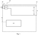
- Fig. 1 10 shows a DC charging column 100 for charging a battery of an electric vehicle.
- the DC charging station 100 comprises two DC charging station input connections 102, 104 for an input DC voltage V E with a first voltage range from 0V to 200V or from 0V to 920 V, ground potential 0V being present at the DC charging station input connection 104.
- the DC input voltage is provided by a central unit and can be built up to + 1000V against earth or + -500 V against earth within the framework of a DC bus supply.
- a DC-DC converter 106 which forms a first DC-DC converter, for converting the DC input voltage V E into an DC output voltage V A with a second voltage range of 1000 V.
- the DC-DC converter 106 also has two DC voltage charging column output connections 108, 110 for providing the DC output voltage V A to the electric vehicle , a potential of 500V being present at the DC charging station output connection 108 and a potential of -500V being present at the DC charging station output connection 110.
- the DC voltage charging column 106 also has a control unit 112 with an Ethernet interface 114 for communication between the DC voltage charging column 106 and the central unit.
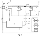
- Fig. 2 shows a DC charging station 200, which comprises the components 102 to 114 of the DC charging station 100 and a system error switch 202, an emergency stop switch 204, an isolation switch 206 and two main switches 208, 210.
- the switches 202 to 206 are connected to the control unit 112.
- the main switches 208, 210 are each connected in series between the DC charging station input terminals 102, 104 and the DC converter 106. If one of the switches 202 to 206 is actuated, these generate a signal which actuates the main switches 208, 210 in such a way that the DC / DC converter 106 is electrically isolated from the DC charging station input terminals 102, 104.
- the DC charging station 200 comprises an insulation measuring unit 212, which measures the insulation of the DC charging station 200 to earth. If the measured insulation exceeds a predetermined threshold value, the insulation measurement unit 212 actuates the isolation switch 206 directly, that is to say without the involvement of the control unit, which in turn generates an isolation signal which actuates the main switches 208, 210 in such a way that the DC / DC converter 106 is electrically connected to the DC charging station input connections 102, 104 is separated or isolated.
- an insulation measuring unit 212 which measures the insulation of the DC charging station 200 to earth. If the measured insulation exceeds a predetermined threshold value, the insulation measurement unit 212 actuates the isolation switch 206 directly, that is to say without the involvement of the control unit, which in turn generates an isolation signal which actuates the main switches 208, 210 in such a way that the DC / DC converter 106 is electrically connected to the DC charging station input connections 102, 104 is separated or isolated.
- the emergency stop switch 204 can be operated by a DC charging station user in an emergency.
- the emergency stop switch 204 generates an emergency stop signal which actuates the main switches 208, 210 in such a way that the DC voltage converter 106 is electrically isolated from the DC voltage charging column input connections 102, 104.
- the system error switch 202 may be actuated by the control unit 112 and generate a system error signal that actuates the main switches 208, 210 in such a way that the DC / DC converter 106 is electrically isolated from the DC charging station input terminals 102, 104.
- the control unit 112 of Fig. 2 further includes an electric vehicle communication interface 214, which forms a second communication interface, for communication of the DC charging station 200 with the electric vehicle.
- the electric vehicle communication interface comprises three protocol interfaces for the CCS protocol 216, for the Chademo protocol 218 and for the Tesla Supercharger protocol 220.
- the three protocol interfaces are implemented as computers 222.
- the computer 222 and / or the control unit 112 comprise a mini PC or a single board computer, such as Raspberry Pi, iOS or the like.
- the DC charging station 200 further includes a power measurement unit 224, which is connected to the DC charging station input connections 102 and 104 and which determines the power delivered to the electric vehicle and / or the charging time.
- the charging energy value comprises the product of the charging time or charging time value and charging power.
- the charging energy value and / or the charging time value serve as the basis for calculating a selling price for a battery charge and / or as customer information.
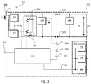
- Fig. 3 shows a DC voltage charging column 300, which comprises the components 102 to 114 of the DC voltage charging column 100, the components 202 to 224 of the DC voltage charging column 200 and a second DC voltage converter 302.
- the second DC-DC converter 302 is optionally operated in parallel or in series with the DC-DC converter 106.
- the DC charging station 300 comprises two switches 304, 306, which form a switching matrix 308.
- the switch 304 is connected to a first input connection of the DC / DC converter 106 and connects the first input connection of the DC / DC converter 106 either to a first input connection of the DC / DC converter 302 or to the DC column input connection 104.
- the switch 306 is connected to the first input connection of the DC / DC converter 302 and connects the first input connection of the DC / DC converter 302 either to the first input connection of the DC / DC converter 106 or to DC column input connection 102.
- the switches 304 and 306 are actuated by the control unit 112 such that the DC / DC converters 106, 302 are either connected in parallel or in series.
- a series connection of the DC voltage converters 106, 302 achieves an addition of the output DC voltages of the DC voltage converters 106, 302.
- a parallel connection of the DC voltage converters 106, 302 achieves an increase in an output DC current of the DC voltage converters 106, 302.
- An increase in output DC current with the same DC output voltage V A causes an increase in the output power the DC voltage converter 106, 302.
- the DC voltage charging column 300 can thus provide different charging voltages and charging powers. For example, when a lithium ion battery is charged, it is charged at the beginning with maximum charging power and the charging power is reduced in the further course.
- All switches 202 to 210 and 304, 306 can be used as relays, contactors or semiconductor switches, e.g. FET or bipolar transistor.
Landscapes
- Engineering & Computer Science (AREA)
- Power Engineering (AREA)
- Transportation (AREA)
- Mechanical Engineering (AREA)
- Life Sciences & Earth Sciences (AREA)
- Sustainable Development (AREA)
- Sustainable Energy (AREA)
- Charge And Discharge Circuits For Batteries Or The Like (AREA)
- Electric Propulsion And Braking For Vehicles (AREA)
Abstract
Description
- Die vorliegende Erfindung betrifft eine Gleichspannungsladesäule zum Laden eines Elektrofahrzeugs.
- Zum Laden von Elektrofahrzeugen mit Strom werden im Allgemeinen Ladevorrichtungen eingesetzt. Im Heimbereich nennt man diese Wallbox, da sie meistens an einer Hauswand befestigt sind. Im öffentlichen Raum werden häufig so genannte Ladesäulen aufgestellt. Wallboxen und Ladesäulen haben meist eine oder mehrere Steckdosen. Die Steckdosen werden auch als Ladepunkte bezeichnet. Ein Ladekabel mit Stecker ist an der Steckdose anschließbar oder bereits angeschlagen und verbindet das Elektrofahrzeug elektrisch mit der Ladevorrichtung.
- Es sind verschiedene Steckverbindungstypen bekannt, so z. B.:
- Schuko-Stecker;
- IEC 62196-2 Typ 1, eine Einphasen-Wechselstromverbindung;
- IEC 62196-2 Typ 2, eine Ein- und Dreiphasenwechselstromverbindung und
- IEC 62196-2 Typ 3, eine Ein- und Dreiphasenwechselstromverbindung mit Schutzmechanismen
- Typ-2-Steckverbindungen werden überwiegend in Europa eingesetzt und erlauben auch das Laden mit Gleichstrom bei Leistungsabgaben bis 120kW (Typ-2 Tesla - Gleichstromladen über Typ2-Stecker.
- Beim Laden mit Wechselstrom ist in den Elektrofahrzeugen meist ein Wandler vorgesehen, der den Wechselstrom in den für das Batterieladen notwendigen Gleichstrom wandelt. Für schnelles Laden mit hoher Leistung wäre jedoch ein nachteilig großer und teurer Wandler in jedem Elektrofahrzeug notwendig. Deshalb setzt die Industrie beim Schnellladen zunehmend auf Gleichspannungs- bzw. Gleichstromladesäulen, auch DC-Säule, DC-Ladesäule oder DC-Schnell-Lader genannt.
- Folgende Schnelllade-Steckverbindungen haben sich bisher etabliert:
- CCS, Combined Charching System, zu Deutsch: kombiniertes Ladesystem, ist ein von deutschen Automobilherstellern entwickelter und seit 2014 EU-weit bindender Standard, der das Laden mit Wechselstrom und Gleichstrom beschreibt. Hierbei ist ein elektrofahrzeugseitiger Stecker für das Wechselstromladen mit einem Typ-2-Stecker und für das Gleichstromladen mit zwei zusätzlichen Hochleistungs-Gleichstromlade-Pins ausgestattet.
- Chademo ist ein Standard, der u. a. von japanischen Automobilherstellern entwickelt wurde.
- Tesla Supercharger ist eine proprietäre Technologie von Tesla für das Laden von Tesla-Elektrofahrzeugen.
- Aus der deutschen Patentanmeldung
DE102015110023 ist ferner eine Ladestation bzw. Zentraleinheit zum Laden eines Plug-In-Kraftfahrzeuges an einer Ladesäule bekannt, wobei diese Ladestation einen Leistungstransformator, mehrere Gleichrichtermodule und einen rückspeisefähigen Pufferspeicher umfasst. - Somit besteht die Aufgabe der vorliegenden Erfindung darin, das Zusammenspiel einer Gleichspannungsladesäule mit einer Zentraleinheit zu verbessern.
- Erfindungsgemäß wird eine Gleichspannungsladesäule zum Laden eines Elektrofahrzeugs gemäß Anspruch 1 bereitgestellt.
- Die erfindungsgemäße Gleichspannungsladesäule umfasst vorzugsweise zwei Gleichspannungsladesäulen-Eingangsanschlüsse für eine Eingangsgleichspannung mit einem ersten Spannungsbereich, wobei die Eingangsgleichspannung von einer Zentraleinheit bereitgestellt wird. Ferner umfasst die erfindungsgemäße Gleichspannungsladesäule einen ersten Gleichspannungswandler zum Wandeln der Eingangsgleichspannung in eine Ausgangsgleichspannung mit einem zweiten Spannungsbereich, sowie zwei Gleichspannungsladesäulen-Ausgangsanschlüsse zum Bereitstellen der Ausgangsgleichspannung an das Elektrofahrzeug. Die erfindungsgemäße Gleichspannungsladesäule kann ferner eine Steuereinheit mit einer ersten Kommunikationsschnittstelle zur Kommunikation zwischen der Gleichspannungsladesäule und der Zentraleinheit umfassen.
- Gleichspannungsladesäulen werden beispielsweise auch als Gleichstromladesäulen, DC-Säule, DC-Ladesäule oder DC-Schnell-Lader bezeichnet.
- Der Begriff Elektrofahrzeug soll vorzugsweise folgende Bedeutungen umfassen:
- Reine Elektrofahrzeuge, angetrieben allein mit Akkustrom, englische Bezeichnung Battery Electric Vehicle, auch Batterieelektrische Fahrzeuge genannt;
- Fahrzeuge mit Elektroantrieb und Range-Extender;
- Hybridfahrzeuge, englisch Hybrid Electric Vehicle;
- Plug-In-Hybride, englisch Plug-In Hybrid Electric Vehicle und
- Brennstoffzellenfahrzeuge, englisch Fuel Cell Vehicle.
- Laden bezeichnet dabei vorzugsweise einem Akkumulator elektrische Energie zum Aufladen zuzuführen. Akkumulatoren können auch als Akku oder Batterie bezeichnet werden. Ihr Einsatz in einem Elektrofahrzeug wird vorzugsweise als Antriebs- oder Traktionsbatterie umschrieben.
- Es ist generell wünschenswert Batterien schnell aufladen zu können. Insbesondere auf langen Fahrten, die die Reichweite einer Elektrofahrzeugbatterie überschreitet, ist ein schnelles Laden von Vorteil. Eine Batterie kann entweder über lange Zeit mit wenig Leistung geladen werden oder mit hoher Leistung in kurzer Zeit; die Ladeenergie ist gleich Leistung mal Ladezeit.
- Ein Gleichspannungswandler, auch DC-DC-Wandler genannt, englisch DC-DC Converter, bezeichnet im Allgemeinen eine elektrische Schaltung, die eine am Eingang zugeführte Gleichspannung in eine Gleichspannung mit höherem, niedrigerem oder invertiertem Spannungsniveau umwandelt. Gleichspannungswandler weisen typischerweise zwei Eingangs- und zwei Ausgangsanschlüsse auf.
- In einer bevorzugten Ausführungsform überträgt oder empfängt die Steuereinheit über die erste Kommunikationsschnittstelle wenigstens eine der folgenden Informationen:
- Status der Gleichspannungsladesäule und/oder
- Daten über die maximal von der Gleichspannungsladesäule abgegebenen Leistung und/oder
- Ladeenergiewert und/oder
- Ladezeitwert und/oder
- Elektrofahrzeugidentifikationsinformation und/oder
- Softwareupdate-Daten.
- Der Status der Gleichspannungssäule umfasst dabei z.B.:
- eine Information darüber, ob ein Elektrofahrzeug zum Laden angeschlossen ist oder nicht und/oder
- eine Information darüber, ob ein Elektrofahrzeug gerade geladen wird und/oder
- eine Information über eine Verschaltung ein oder mehrerer der Gleichspannungswandler.
- die verfügbare Energie, Leistung, Spannung, Betriebszustand und zukünftige Betriebszustände der Zentraleinheit (z.B. Energieverfügbarkeitsprognosen auf Grund der Energielieferverbindungen (Photovoltaik-Strom, Biomassestromproduktion)).
- Der Ladeenergiewert umfasst vorzugsweise das Produkt aus Ladezeit und Ladeleistung. Der Ladeenergiewert und/oder der Ladezeitwert können als Grundlage zur Berechnung des Verkaufspreises für die Batterieladung und/oder als Kundeninformation dienen.
- Anhand der Elektrofahrzeugidentifikationsinformation kann die Zentraleinheit oder die Gleichspannungsladesäule ermitteln, welche maximale Ladeleistung für das jeweils angeschlossene Elektrofahrzeug zulässig ist und eine entsprechende maximale Leistung abgeben und diese der Gleichspannungsladesäule zur Verfügung stellen.
- Eine Zentraleinheit kann ein oder mehrere Gleichspannungsladesäulen umfassen und steuern.
- Die erfindungsgemäße Gleichspannungsladesäule kann ferner die Energieeffizienz verbessern.
- Gemäß einer weiteren bevorzugten Ausführungsform kann die Steuereinheit an der ersten Kommunikationsschnittstelle einen seriellen Kommunikationsstandard, insbesondere Ethernet, unterstützen. Leitungsgebundene Kommunikation, wie Ethernet, kann gegenüber drahtloser Kommunikation zwischen Zentraleinheit und Gleichspannungsladesäule von Vorteil sein, um z.B. den Einfluss von in der Gleichspannungsladesäule oder der Umgebung erzeugter Hochfrequenz-Störung zu verringern. Ethernet-Kabel, Router und Netzwerkkarten sind im Allgemeinen preiswert und erlauben hohe Datenraten; häufig sind PCs und Industrierechner bereits serienmäßig mit einer Ethernet-Schnittstelle ausgestattet und können für die Steuereinheit bzw. die Zentraleinheit eingesetzt werden. Für Ethernet-Kupferkabel sind vorteilhafte Linklängen von bis zu ca. 100 m möglich, mit Ethernet-Glasfaserkabeln üblicherweise noch weit mehr.
- In einer weiteren vorteilhaften Weiterbildung der Erfindung umfasst die Steuereinheit eine zweite Kommunikationsschnittstelle zur Kommunikation zwischen der Gleichspannungsladesäule und dem Elektrofahrzeug.
- Über die zweite Kommunikationsschnittstelle können insbesondere die Steuereinheit und ein Batteriemanagementsystem des Elektrofahrzeugs anhand eines Kommunikationsprotokolls miteinander kommunizieren.
- Das Batteriemanagementsystem kann z.B.:
- den aktuellen Ladezustand der Elektrofahrzeugbatterie und/oder
- die Gleichspannung und maximale Ladestromstärke bzw. maximale Ladeleistung und/oder
- Momentanspannung der Batterie und/oder
- Batterietemperatur
- Über die erste Kommunikationsschnittstelle kann die Steuereinheit Softwareupdate-Daten empfangen, um ein Kommunikationsprotokoll für die zweite Kommunikationsschnittstelle zu aktualisieren. So kann die Gleichspannungsladesäule z. B. auch stets mit neuesten Elektrofahrzeugen während der Ladung kommunizieren.
- Gemäß einer Weiterbildung kann die Steuereinheit an der zweiten Kommunikationsschnittstelle wenigstens zwei verschiedene Kommunikationsprotokolle unterstützen, z.B. Chademo und/oder CCS und/oder Tesla Supercharger. An einer derartigen Gleichspannungsladesäule können so Elektrofahrzeuge mit verschiedenen Steckverbindungen an einem Ladepunkt geladen werden.
- Eine weitere bevorzugte Ausführungsform kann darin bestehen, dass die Gleichspannungsladesäule mit einem zweiten Gleichspannungswandler ausgestattet ist, der wahlweise zum ersten Gleichspannungswandler parallel oder in Reihe geschaltet ist.
- Eine Reihenschaltung der Gleichspannungswandler kann eine Addition der Ausgangsgleichspannungen der Gleichspannungswandler erzielen. Eine Parallelschaltung der Gleichspannungswandler kann eine Erhöhung eines Ausgangsgleichstromes der Gleichspannungswandler erzielen. Eine Ausgangsgleichstrom-Erhöhung bei gleicher Ausgangsgleichspannung bewirkt eine Erhöhung der Ausgangsleistung der Gleichspannungswandler. So kann die Gleichspannungsladesäule verschiedene Ladespannungen und Ladeleistungen bereitstellen. Beispielsweise wird beim Laden einer Lithiumionenbatterie am Anfang mit maximaler Ladeleistung geladen und die Ladeleistung im weiteren Verlauf verringert. Die Gleichspannungsladesäule kann mehrere Ladepunkte umfassen. Je nach Verlauf kann die Steuereinheit Gleichspannungswandler von einem auf einen anderen Ladepunkt schalten. Die Gleichspannungsladesäule kann einen dritten, vierten und ggf. weitere Gleichspannungswandler umfassen. Die Reihen- bzw. Parallelschaltung aller Gleichspannungswandler erzielt im Wesentlichen die vorgenannten Wirkungen. Die erfindungsgemäße Gleichspannungsladesäule kann damit modular und somit einfach erweiterungsfähig ausgelegt werden. Dies ist zum Beispiel für die Errichtung in vorhandener öffentlicher sowie privater baulicher Infrastruktur von Vorteil.
- Gemäß einer weiteren bevorzugten Ausführungsform umfasst die Gleichspannungsladesäule eine Schaltmatrix, die mit der Steuereinheit, mit wenigstens einem Eingangsanschluss jedes oder zumindest mehrerer Gleichspannungswandler und mit den Gleichspannungsladesäulen-Eingangsanschlüssen verbunden ist. Die Steuereinheit kann die Schaltmatrix derart ansteuern, dass alle Gleichspannungswandler entweder parallel oder in Reihe geschaltet sind.
- Vorzugsweise umfasst die Gleichspannungsladesäule eine Isolationsmesseinheit, die mit den Gleichspannungsladesäulen-Eingangsanschlüssen und mit Erde bzw. Masse verbunden ist, wobei die Isolationsmesseinheit die Isolation der Gleichspannungsladesäule zu Erde misst und in Abhängigkeit der Messung die Gleichspannungsladesäule vom Elektrofahrzeug elektrisch trennt. Die Isolationsmesseinheit kann zur Beurteilung von Funktionsfähigkeit und Sicherheit der Gleichspannungsladesäule dienen und kann ferner frühzeitig Mängel aufzeigen.
- Die Zentraleinheit kann eine zentrale Gleichspannungsquelle, einen Transformator und/oder einen Pufferspeicher umfassen oder einer Direkteinspeisung aus Photovoltaik-Erzeugung, die die Eingangsgleichspannung erzeugen und ein oder mehrere Gleichspannungsladesäulen zur Verfügung stellt. Die Isolationsmesseinheit kann vorteilhaft in jeder einzelnen Gleichspannungsladesäule angeordnet werden und nur die lokale Isolation in der jeweiligen Gleichspannungsladesäule ermitteln und diese ggf. vom Elektrofahrzeug trennen.
- Ferner kann die Gleichspannungsladesäule nach einem der vorhergehenden Ansprüche mit einer Leistungsmesseinheit ausgestattet sein, die mit den Gleichspannungsladesäulen-Eingangsanschlüssen verbunden ist und die die an das Elektrofahrzeug abgegebene Leistung und/oder die Ladezeit ermittelt. Der Ladeenergiewert umfasst vorzugsweise das Produkt aus Ladezeit, bzw. Ladezeitwert, und Ladeleistung. Der Ladeenergiewert und/oder der Ladezeitwert können als Grundlage zur Berechnung eines Verkaufspreises für die Batterieladung und/oder als Kundeninformation dienen.
- Darüber hinaus kann die Gleichspannungsladesäule eine Temperaturmesseinheit umfassen, die ausgelegt ist die Leistungsabgabe der Gleichspannungsladesäule in Abhängigkeit der gemessenen Temperatur zu steuern. Gleichspannungsladesäulen sollen vorzugsweise in einem Umgebungstemperaturbereich von -20°C bis 45°C volle Leistung abgeben können. Nach dem ersten Jouleschen Gesetz erzeugen stromführende Bauelemente der Gleichspannungsladesäule im Allgemeinen eine bestimmte Wärmeenergie. Ermittelt die Temperaturmesseinheit eine Umgebungstemperatur oder Gleichspannungsladesäulentemperatur über einem vorbestimmten Grenzwert, so kann die Temperaturmesseinheit mittels der Steuereinheit die Leistungsabgabe der Gleichspannungsladesäule und damit der stromführenden Bauelemente reduzieren, um etwa ein Überhitzen, Schmelzen oder in Brand geraten der Bauelemente zu vermeiden.
- Gemäß einer Weiterbildung umfasst die Gleichspannungsladesäule einen Hauptschalter, der in Reihe zwischen dem ersten Gleichspannungswandler und einem der Gleichspannungsladesäulen-Eingangsanschlüsse geschaltet ist, wobei der Hauptschalter ausgelegt ist den ersten Gleichspannungswandler wahlweise mit einem der Gleichspannungsladesäulen-Eingangsanschlüsse zu verbinden oder davon zu trennen. Der wenigstens eine Hauptschalter kann dabei in Abhängigkeit eines Notaus-Signals, eines Systemfehlersignals oder der Isolation der Gleichspannungsladesäule zu Erde gesteuert sein. Die Gleichspannungsladesäule kann einen Notaus-Schalter umfassen, den ein Gleichstromladesäulennutzer bedient und der ein Notaus-Signal erzeugt. Die Steuereinheit und/oder die Zentraleinheit können das Systemfehlersignal im Falle einer Fehlfunktion erzeugen. Die Isolationsmesseinheit kann den Hauptschalter in Abhängigkeit der gemessenen Isolation steuern. Ferner kann je Gleichspannungsladesäulen-Eingangsanschluss ein Hauptschalter vorgesehen sein.
- Der Begriff "verbunden" umfasst vorzugsweise die Bedeutung "elektrisch verbunden", "elektrisch leitend verbunden" und "gekoppelt".
- Ausführungsbeispiele der Erfindung werden anhand der Zeichnungen und der nachfolgenden Beschreibung erläutert. Es zeigen:
- Fig. 1
- eine Gleichspannungsladesäule gemäß der Erfindung,
- Fig. 2
- eine weitere Gleichspannungsladesäule gemäß der Erfindung und
- Fig. 3
- eine weitere Gleichspannungsladesäule gemäß der Erfindung.
-
Fig. 1 zeigt eine Gleichspannungsladesäule 100 zum Laden einer Batterie eines Elektrofahrzeugs. Die Gleichspannungsladesäule 100 umfasst zwei Gleichspannungsladesäulen-Eingangsanschlüsse 102, 104 für eine Eingangsgleichspannung VE mit einem ersten Spannungsbereich von 0V bis 200V oder von 0V bis 920 V, wobei am Gleichspannungsladesäulen-Eingangsanschluss 104 Massepotential 0V anliegt. Die Eingangsgleichspannung wird von einer Zentraleinheit bereitgestellt und kann sowohl +1000V gegen Erde oder +-500 V gegen Erde im Rahmen einer DC-Bus Versorgung aufgebaut sein. - Ferner zeigt
Fig. 1 einen Gleichspannungswandler 106, der einen ersten Gleichspannungswandler bildet, zum Wandeln der Eingangsgleichspannung VE in eine Ausgangsgleichspannung VA mit einem zweiten Spannungsbereich von 1000 V. Der Gleichspannungswandler 106 weist außerdem zwei Gleichspannungsladesäulen-Ausgangsanschlüsse 108, 110 zum Bereitstellen der Ausgangsgleichspannung VA an das Elektrofahrzeug auf, wobei am Gleichspannungsladesäulen-Ausgangsanschluss 108 ein Potential von 500V und am Gleichspannungsladesäulen-Ausgangsanschluss 110 ein Potential von -500V anliegt. - Die Gleichspannungsladesäule 106 weist ferner eine Steuereinheit 112 mit einer Ethernet-Schnittstelle 114 zur Kommunikation zwischen der Gleichspannungsladesäule 106 und der Zentraleinheit auf.
-
Fig. 2 zeigt eine Gleichspannungsladesäule 200, die die Bauelementen 102 bis 114 der Gleichspannungsladesäule 100 umfasst sowie einen Systemfehlerschalter 202, einen Notaus-Schalter 204, einen Isolationsschalter 206 und zwei Hauptschalter 208, 210. Die Schalter 202 bis 206 sind mit der Steuereinheit 112 verbunden. Die Hauptschalter 208, 210 sind jeweils in Reihe zwischen den Gleichspannungsladesäulen-Eingangsanschlüssen 102, 104 und dem Gleichspannungswandler 106 geschaltet. Wird einer der Schalter 202 bis 206 betätigt so erzeugen diese ein Signal, das die Hauptschalter 208, 210 derart betätigt, dass der Gleichspannungswandler 106 elektrisch von den Gleichspannungsladesäulen-Eingangsanschlüssen 102, 104 getrennt bzw. isoliert wird. Die Gleichspannungsladesäule 200 umfasst eine Isoliermesseinheit 212, die die Isolation der Gleichspannungsladesäule 200 zu Erde misst. Überschreitet die gemessene Isolation einen vorbestimmten Schwellwert, so betätigt die Isolationsmesseinheit 212 direkt, d.h. ohne Mitwirkung der Steuereinheit, den Isolationsschalter 206, der wiederum ein Isolationssignal erzeugt, das die Hauptschalter 208, 210 derart betätigt, dass der Gleichspannungswandler 106 elektrisch von den Gleichspannungsladesäulen-Eingangsanschlüssen 102, 104 getrennt, bzw. isoliert wird. - Der Notaus-Schalter 204 kann von einem Gleichstromladesäulennutzer in einem Notfall betätigt werden. Der Notaus-Schalter 204 erzeugt ein Notaus-Signal, das die Hauptschalter 208, 210 derart betätigt, dass der Gleichspannungswandler 106 elektrisch von den Gleichspannungsladesäulen-Eingangsanschlüssen 102, 104 getrennt, bzw. isoliert wird.
- Der Systemfehlerschalter 202 kann von der Steuereinheit 112 betätigt werden und ein Systemfehlersignal erzeugen, das die Hauptschalter 208, 210 derart betätigt, dass der Gleichspannungswandler 106 elektrisch von den Gleichspannungsladesäulen-Eingangsanschlüssen 102, 104 getrennt, bzw. isoliert wird.
- Die Steuereinheit 112 von
Fig. 2 umfasst ferner eine Elektrofahrzeug-Kommunikationsschnittstelle 214, die eine zweite Kommunikationsschnittstelle bildet, zur Kommunikation der Gleichspannungsladesäule 200 mit dem Elektrofahrzeug. Die Elektrofahrzeug-Kommunikationsschnittstelle umfasst drei Protokollschnittstellen für das CCS-Protokoll 216, für das Chademo-Protokoll 218 und für das Tesla-Supercharger-Protokoll 220. Die drei Protokollschnittstellen sind als Computer 222 implementiert. Der Computer 222 und/oder die Steuereinheit 112 umfassen einen Mini-PC oder einen Einplatinenrechner, wie Raspberry Pi, Arduino oder dergleichen. - Die Gleichspannungsladesäule 200 umfasst ferner eine Leistungsmesseinheit 224, die mit den Gleichspannungsladesäulen-Eingangsanschlüssen 102 und 104 verbunden ist und die die an das Elektrofahrzeug abgegebene Leistung und/oder die Ladezeit ermittelt. Der Ladeenergiewert umfasst das Produkt aus Ladezeit bzw. Ladezeitwert und Ladeleistung. Der Ladeenergiewert und/oder der Ladezeitwert dienen als Grundlage zur Berechnung eines Verkaufspreises für eine Batterieladung und/oder als Kundeninformation.
-
Fig. 3 zeigt eine Gleichspannungsladesäule 300, die die Bauelementen 102 bis 114 der Gleichspannungsladesäule 100, die Bauelement 202 bis 224 der Gleichspannungsladesäule 200 sowie einen zweiten Gleichspannungswandler 302 umfasst. Der zweite Gleichspannungswandler 302 wird wahlweise parallel oder in Reihe geschaltet zum Gleichspannungswandler 106 betrieben. - Die Gleichspannungsladesäule 300 umfasst zwei Schalter 304, 306, die eine Schaltmatrix 308 bilden. Der Schalter 304 ist mit einem ersten Eingangsanschluss des Gleichspannungswandlers 106 verbunden und verbindet den ersten Eingangsanschluss des Gleichspannungswandlers 106 wahlweise mit einem ersten Eingangsanschluss des Gleichspannungswandlers 302 oder mit dem Gleichspannungssäulen-Eingangsanschluss 104.
- Der Schalter 306 ist mit dem ersten Eingangsanschluss des Gleichspannungswandlers 302 verbunden und verbindet den ersten Eingangsanschluss des Gleichspannungswandlers 302 wahlweise mit dem ersten Eingangsanschluss des Gleichspannungswandlers 106 oder mit Gleichspannungssäulen-Eingangsanschluss 102.
- Die Schalter 304 und 306 werden von der Steuereinheit 112 derart betätigt, dass die Gleichspannungswandler 106, 302 entweder parallel oder in Reihe geschalten sind.
- Eine Reihenschaltung der Gleichspannungswandler 106, 302 erzielt eine Addition der Ausgangsgleichspannungen der Gleichspannungswandler 106, 302. Eine Parallelschaltung der Gleichspannungswandler 106, 302 erzielt eine Erhöhung eines Ausgangsgleichstromes der Gleichspannungswandler 106, 302. Eine Ausgangsgleichstrom-Erhöhung bei gleicher Ausgangsgleichspannung VA bewirkt eine Erhöhung der Ausgangsleistung der Gleichspannungswandler 106, 302. So kann die Gleichspannungsladesäule 300 verschiedene Ladespannungen und Ladeleistungen bereitstellen. Beispielsweise wird beim Laden einer Lithiumionenbatterie am Anfang mit maximaler Ladeleistung geladen und die Ladeleistung im weiteren Verlauf verringert.
- Alle Schalter 202 bis 210 und 304, 306 können als Relais, Schütz oder Halbleiterschalter, z.B. FET oder Bipolar-Transistor, ausgelegt sein.
Claims (13)
- Gleichspannungsladesäule (100; 200; 300) zum Laden eines Elektrofahrzeugs umfassend:- zwei Gleichspannungsladesäulen-Eingangsanschlüsse (102, 104) für eine Eingangsgleichspannung (VE) mit einem ersten Spannungsbereich bereitgestellt von einer Zentraleinheit;- einen ersten Gleichspannungswandler (106; 302) zum Wandeln der Eingangsgleichspannung (VE) in eine Ausgangsgleichspannung (VA) mit einem zweiten Spannungsbereich;- zwei Gleichspannungsladesäulen-Ausgangsanschlüsse (108, 110) zum Bereitstellen der Ausgangsgleichspannung (VA) an das Elektrofahrzeug;dadurch gekennzeichnet, dass
die Gleichspannungsladesäule (100; 200; 300) eine Steuereinheit (112) mit einer ersten Kommunikationsschnittstelle (114) zur Kommunikation zwischen der Gleichspannungsladesäule (100; 200; 300) und der Zentraleinheit umfasst. - Gleichspannungsladesäule (100; 200; 300) nach Anspruch 1, wobei die Steuereinheit (112) über die erste Kommunikationsschnittstelle (114) wenigstens eine der folgenden Informationen überträgt oder empfängt:- Status der Gleichspannungsladesäule,- Daten über die maximal von der Gleichspannungsladesäule abgegebenen Leistung,- Ladeenergiewert,- Ladezeitwert,- Elektrofahrzeugidentifikationsinformation,- Softwareupdate-Daten.
- Gleichspannungsladesäule (100; 200; 300) nach Anspruch 1 oder 2, wobei die Steuereinheit an der ersten Kommunikationsschnittstelle (114) einen seriellen Kommunikationsstandard, insbesondere Ethernet, unterstützt.
- Gleichspannungsladesäule (100; 200; 300) nach einem der vorhergehenden Ansprüche, wobei die Steuereinheit (112) eine zweite Kommunikationsschnittstelle (214) zur Kommunikation zwischen der Gleichspannungsladesäule (100; 200; 300) und dem Elektrofahrzeug umfasst.
- Gleichspannungsladesäule nach Anspruch 4, wobei die Steuereinheit (112) an der zweiten Kommunikationsschnittstelle (214) wenigstens zwei verschiedene Kommunikationsprotokolle (216, 218, 220) an einem Ladepunkt unterstützt.
- Gleichspannungsladesäule (100; 200; 300) nach einem der vorhergehenden Ansprüche mit einem zweiten Gleichspannungswandler (302), der wahlweise zum ersten Gleichspannungswandler (106) parallel oder in Reihe geschaltet ist.
- Gleichspannungsladesäule nach Anspruch 5 mit einem dritten und vierten Gleichspannungswandler (106; 302), wobei alle Gleichspannungswandler (106; 302) wahlweise parallel oder in Reihe geschaltet sind.
- Gleichspannungsladesäule nach Anspruch 6 oder 7, mit einer Schaltmatrix (308), die mit der Steuereinheit (112), mit wenigstens einem Eingangsanschluss jedes Gleichspannungswandlers (106; 302) und mit den Gleichspannungsladesäulen-Eingangsanschlüssen (102, 104) verbunden ist, wobei die Steuereinheit (112) die Schaltmatrix (308) derart ansteuert, dass alle Gleichspannungswandler (106; 302) entweder parallel oder in Reihe geschaltet sind.
- Gleichspannungsladesäule (100; 200; 300) nach einem der vorhergehenden Ansprüche mit einer Isolationsmesseinheit (212), die mit den Gleichspannungsladesäulen-Eingangsanschlüssen (102, 104) und mit Erde verbunden ist, wobei die Isolationsmesseinheit (212) die Isolation der Gleichspannungsladesäule (100; 200; 300) zu Erde misst und in Abhängigkeit der Messung die Gleichspannungsladesäule (100; 200; 300) vom Elektrofahrzeug elektrisch trennt.
- Gleichspannungsladesäule (100; 200; 300) nach einem der vorhergehenden Ansprüche mit einer Leistungsmesseinheit (224), die mit den Gleichspannungsladesäulen-Eingangsanschlüssen (102, 104) verbunden ist und die die an das Elektrofahrzeug abgegebene Leistung und/oder die Ladezeit ermittelt.
- Gleichspannungsladesäule (100; 200; 300) nach einem der vorhergehenden Ansprüche mit einer Temperaturmesseinheit, die ausgelegt ist die Leistungsabgabe der Gleichspannungsladesäule (100; 200; 300) in Abhängigkeit der gemessenen Temperatur zu steuern.
- Gleichspannungsladesäule (100; 200; 300) nach einem der vorhergehenden Ansprüche mit wenigstens einem Hauptschalter (208, 210), der in Reihe zwischen dem ersten Gleichspannungswandler (106; 302) und einem der Gleichspannungsladesäulen- Eingangsanschlüsse (102, 104) geschaltet ist, wobei der Hauptschalter (208, 210) ausgelegt ist den ersten Gleichspannungswandler (106; 302) wahlweise mit einem der Gleichspannungsladesäulen-Eingangsanschlüsse (102, 104) zu verbinden oder davon zu trennen.
- Gleichspannungsladesäule (100; 200; 300) nach Anspruch 12, wobei der wenigstens eine Hauptschalter (208, 210) in Abhängigkeit eines Notaus-Signals, eines Systemfehlersignals oder der Isolation der Gleichspannungsladesäule (100; 200; 300) zu Erde gesteuert wird.
Priority Applications (6)
| Application Number | Priority Date | Filing Date | Title |
|---|---|---|---|
| EP18020275.6A EP3587164B1 (de) | 2018-06-22 | 2018-06-22 | System mit zentraleinheit und mehreren gleichspannungsladesäulen zum laden von elektrofahrzuegen |
| EP23213856.0A EP4353515A1 (de) | 2018-06-22 | 2018-06-22 | System mit zentraleinheit und mehreren gleichspannungsladesäulen zum laden von elektrofahrzuegen |
| US17/254,554 US11491886B2 (en) | 2018-06-22 | 2019-06-21 | DC voltage charging post for charging an electric vehicle |
| PCT/EP2019/025191 WO2019242891A1 (de) | 2018-06-22 | 2019-06-21 | Gleichspannungsladesaeule zum laden eines elektrofahrzeugs |
| CN201980046681.6A CN112424015B (zh) | 2018-06-22 | 2019-06-21 | 用于对电动车充电的dc电压充电桩 |
| KR1020217000877A KR102819236B1 (ko) | 2018-06-22 | 2019-06-21 | 전기 차량을 충전하기 위한 dc 전압 충전 포스트 |
Applications Claiming Priority (1)
| Application Number | Priority Date | Filing Date | Title |
|---|---|---|---|
| EP18020275.6A EP3587164B1 (de) | 2018-06-22 | 2018-06-22 | System mit zentraleinheit und mehreren gleichspannungsladesäulen zum laden von elektrofahrzuegen |
Related Child Applications (1)
| Application Number | Title | Priority Date | Filing Date |
|---|---|---|---|
| EP23213856.0A Division EP4353515A1 (de) | 2018-06-22 | 2018-06-22 | System mit zentraleinheit und mehreren gleichspannungsladesäulen zum laden von elektrofahrzuegen |
Publications (3)
| Publication Number | Publication Date |
|---|---|
| EP3587164A1 true EP3587164A1 (de) | 2020-01-01 |
| EP3587164B1 EP3587164B1 (de) | 2023-12-20 |
| EP3587164C0 EP3587164C0 (de) | 2023-12-20 |
Family
ID=62783973
Family Applications (2)
| Application Number | Title | Priority Date | Filing Date |
|---|---|---|---|
| EP23213856.0A Pending EP4353515A1 (de) | 2018-06-22 | 2018-06-22 | System mit zentraleinheit und mehreren gleichspannungsladesäulen zum laden von elektrofahrzuegen |
| EP18020275.6A Active EP3587164B1 (de) | 2018-06-22 | 2018-06-22 | System mit zentraleinheit und mehreren gleichspannungsladesäulen zum laden von elektrofahrzuegen |
Family Applications Before (1)
| Application Number | Title | Priority Date | Filing Date |
|---|---|---|---|
| EP23213856.0A Pending EP4353515A1 (de) | 2018-06-22 | 2018-06-22 | System mit zentraleinheit und mehreren gleichspannungsladesäulen zum laden von elektrofahrzuegen |
Country Status (5)
| Country | Link |
|---|---|
| US (1) | US11491886B2 (de) |
| EP (2) | EP4353515A1 (de) |
| KR (1) | KR102819236B1 (de) |
| CN (1) | CN112424015B (de) |
| WO (1) | WO2019242891A1 (de) |
Families Citing this family (3)
| Publication number | Priority date | Publication date | Assignee | Title |
|---|---|---|---|---|
| DE102019006065A1 (de) * | 2019-08-28 | 2021-03-04 | Kostal Automobil Elektrik Gmbh & Co. Kg | Ladesystem zum Gleichstromladen der Traktionsbatterie eines elektrisch angetriebenen Kraftfahrzeugs |
| KR102926156B1 (ko) * | 2023-03-23 | 2026-02-10 | 엘에스일렉트릭(주) | 전기자동차의 충전 시스템 |
| KR102662798B1 (ko) * | 2023-09-14 | 2024-05-03 | 비테스코 테크놀로지스 게엠베하 | 배터리 충전 스테이션 및 그 작동 방법 |
Citations (5)
| Publication number | Priority date | Publication date | Assignee | Title |
|---|---|---|---|---|
| US20140084843A1 (en) * | 2012-09-27 | 2014-03-27 | Ford Global Technologies, Llc | High Voltage Charge Pack |
| EP2882066A1 (de) * | 2012-07-30 | 2015-06-10 | Mitsubishi Electric Corporation | Lade-/entladevorrichtung |
| DE102015110023A1 (de) | 2015-06-23 | 2016-12-29 | Dr. Ing. H.C. F. Porsche Aktiengesellschaft | Ladestation und Verfahren zum Laden eines Plug-In-Kraftfahrzeuges an einer Ladesäule |
| WO2017137234A1 (de) * | 2016-02-10 | 2017-08-17 | Bayerische Motoren Werke Aktiengesellschaft | Dynamische kommunikation der tatsächlichen ladeleistung |
| EP3321120A1 (de) * | 2016-11-14 | 2018-05-16 | ABB Schweiz AG | Ladeleistungsversorgungssystem für elektrofahrzeugstation |
Family Cites Families (15)
| Publication number | Priority date | Publication date | Assignee | Title |
|---|---|---|---|---|
| JP3214044B2 (ja) * | 1992-03-27 | 2001-10-02 | 株式会社明電舎 | 充電装置 |
| KR100458177B1 (ko) * | 2001-12-06 | 2004-11-26 | 한국철도기술연구원 | 철도차량용 직류가변 주회로 시스템 |
| JP5647057B2 (ja) * | 2010-05-19 | 2014-12-24 | 株式会社日立製作所 | 充電装置、充電制御ユニット及び充電制御方法 |
| NL2004746C2 (en) * | 2010-05-19 | 2011-11-22 | Epyon B V | Charging system for electric vehicles. |
| DE102010041253A1 (de) * | 2010-09-23 | 2012-03-29 | Siemens Aktiengesellschaft | DC-Ladestation für eine Batterie eines Elektrofahrzeugs |
| DE102011079430A1 (de) * | 2011-07-19 | 2013-01-24 | Siemens Aktiengesellschaft | DC-Ladestation zum Aufladen mehrerer Energiespeichereinrichtungen |
| US20130076294A1 (en) * | 2011-09-28 | 2013-03-28 | All Vision LLC. | Electric vehicle charging system and method of supplying power to an electric vehicle charging station |
| DE102012212291A1 (de) * | 2012-07-13 | 2014-02-20 | Siemens Aktiengesellschaft | Modularer Aufbau von DC-Schnellladestationen |
| EP2875985A1 (de) * | 2013-11-22 | 2015-05-27 | Hochschule für angewandte Wissenschaften Deggendorf | Ladestation für Elektrofahrzeuge mit integriertem Energiespeicher |
| KR102253188B1 (ko) * | 2014-08-01 | 2021-05-18 | 엘지이노텍 주식회사 | 전기 자동차의 급속 충전 제어 장치 |
| DE102014115019A1 (de) * | 2014-10-16 | 2016-04-21 | ABL SURSUM Bayerische Elektrozubehör GmbH & Co. KG | Ladestation für Elektrofahrzeuge |
| CN105119334A (zh) * | 2015-08-31 | 2015-12-02 | 深圳驿普乐氏科技有限公司 | 一种宽电压输出范围的变压电路和直流充电桩 |
| DE102016123924A1 (de) * | 2016-12-09 | 2018-06-14 | Dr. Ing. H.C. F. Porsche Aktiengesellschaft | Modulare Leistungselektronik zum Laden eines elektrisch betriebenen Fahrzeugs |
| WO2019011905A2 (en) * | 2017-07-10 | 2019-01-17 | Abb Schweiz Ag | VARIABLE POWER LOAD |
| US11270243B1 (en) * | 2020-10-01 | 2022-03-08 | Electricfish Energy Inc. | System and method for electrical grid management, risk mitigation, and resilience |
-
2018
- 2018-06-22 EP EP23213856.0A patent/EP4353515A1/de active Pending
- 2018-06-22 EP EP18020275.6A patent/EP3587164B1/de active Active
-
2019
- 2019-06-21 US US17/254,554 patent/US11491886B2/en active Active
- 2019-06-21 KR KR1020217000877A patent/KR102819236B1/ko active Active
- 2019-06-21 CN CN201980046681.6A patent/CN112424015B/zh active Active
- 2019-06-21 WO PCT/EP2019/025191 patent/WO2019242891A1/de not_active Ceased
Patent Citations (5)
| Publication number | Priority date | Publication date | Assignee | Title |
|---|---|---|---|---|
| EP2882066A1 (de) * | 2012-07-30 | 2015-06-10 | Mitsubishi Electric Corporation | Lade-/entladevorrichtung |
| US20140084843A1 (en) * | 2012-09-27 | 2014-03-27 | Ford Global Technologies, Llc | High Voltage Charge Pack |
| DE102015110023A1 (de) | 2015-06-23 | 2016-12-29 | Dr. Ing. H.C. F. Porsche Aktiengesellschaft | Ladestation und Verfahren zum Laden eines Plug-In-Kraftfahrzeuges an einer Ladesäule |
| WO2017137234A1 (de) * | 2016-02-10 | 2017-08-17 | Bayerische Motoren Werke Aktiengesellschaft | Dynamische kommunikation der tatsächlichen ladeleistung |
| EP3321120A1 (de) * | 2016-11-14 | 2018-05-16 | ABB Schweiz AG | Ladeleistungsversorgungssystem für elektrofahrzeugstation |
Also Published As
| Publication number | Publication date |
|---|---|
| US20210268925A1 (en) | 2021-09-02 |
| KR20210024539A (ko) | 2021-03-05 |
| EP3587164B1 (de) | 2023-12-20 |
| CN112424015A (zh) | 2021-02-26 |
| CN112424015B (zh) | 2024-09-24 |
| EP3587164C0 (de) | 2023-12-20 |
| US11491886B2 (en) | 2022-11-08 |
| EP4353515A1 (de) | 2024-04-17 |
| WO2019242891A1 (de) | 2019-12-26 |
| KR102819236B1 (ko) | 2025-06-12 |
Similar Documents
| Publication | Publication Date | Title |
|---|---|---|
| EP2699446B1 (de) | Fahrzeugladevorrichtung | |
| DE112019005692B4 (de) | Hilfsenergiesystem-architektur | |
| AT507703B1 (de) | Energiespeicheranordnung und verfahren zum betrieb einer derartigen anordnung | |
| DE102019128406A1 (de) | Rekonfigurierbares mikronetz | |
| DE202017007360U1 (de) | Rackmontiertes UPS-Gerät für Rechenzentren | |
| DE102019211553A1 (de) | Bidirektionale DC-Wallbox für Elektrofahrzeuge | |
| EP2496436A2 (de) | Ladesystem für elektrofahrzeuge | |
| DE102017104958A1 (de) | Batteriespeichersystem und Bordnetz zur fehlertoleranten Versorgung sicherheitsrelevanter Verbraucher in einem Fahrzeug | |
| DE102014105985A1 (de) | Wandlermodul zur Umwandlung elektrischer Leistung und Wechselrichter für eine Photovoltaikanlage mit mindestens zwei Wandlermodulen | |
| DE102014002819A1 (de) | Elektrische Energiespeichervorrichtung für Kraftfahrzeuge | |
| DE102016013490A1 (de) | Bordladeeinrichtung für ein Kraftfahrzeug zum Laden einer Traktionsbatterie | |
| EP3587164B1 (de) | System mit zentraleinheit und mehreren gleichspannungsladesäulen zum laden von elektrofahrzuegen | |
| DE102016008265A1 (de) | Verfahren zum Betreiben eines Kraftfahrzeugs mit einem umschaltbaren elektrischen Energiespeicher und entsprechende Schaltungsanordnung | |
| DE202023104956U1 (de) | Stromversorgung mit berührungssicherem Stromversorgungskern | |
| WO2021190917A1 (de) | Verfahren, system und vorrichtung zum versorgen eines verbrauchers mit elektrischer energie | |
| EP4473325A1 (de) | Prüfsystem mit basis-wandlern und booster-wandler | |
| EP3549812A1 (de) | Ladesystem und verfahren zum aufladen eines jeweiligen elektrischen energiespeichers mehrerer kraftfahrzeuge sowie stationäre ladevorrichtung und kraftfahrzeug | |
| EP3006253A1 (de) | Anordnung aus mindestens zwei elektrischen traktionsenergiespeichern | |
| WO2019215142A1 (de) | Vorrichtung und verfahren zur energieversorgung eines oder mehrerer verbraucher | |
| DE102019004206A1 (de) | Ladesystem fur ein elektrisch betreibbares Fahrzeug | |
| DE102022200004A1 (de) | Verfahren zum Betreiben eines Ladesystems mit mehreren Ladeeinheiten, sowie Ladesystem mit mehreren Ladeeinheiten | |
| DE102020007865B4 (de) | Ladevorrichtung und Verfahren zum Laden eines elektrischen Energiespeichers eines elektrisch betreibbaren Fahrzeugs | |
| DE102023205223A1 (de) | Speicherbatterie-anschlussmodul, kabelbaum und energiespeichersystem | |
| CN209566874U (zh) | 混合动力汽车后桥电驱系统高压分线盒 | |
| DE102019200871B4 (de) | Ladekabel und Kraftfahrzeug |
Legal Events
| Date | Code | Title | Description |
|---|---|---|---|
| PUAI | Public reference made under article 153(3) epc to a published international application that has entered the european phase |
Free format text: ORIGINAL CODE: 0009012 |
|
| STAA | Information on the status of an ep patent application or granted ep patent |
Free format text: STATUS: REQUEST FOR EXAMINATION WAS MADE |
|
| 17P | Request for examination filed |
Effective date: 20190607 |
|
| AK | Designated contracting states |
Kind code of ref document: A1 Designated state(s): AL AT BE BG CH CY CZ DE DK EE ES FI FR GB GR HR HU IE IS IT LI LT LU LV MC MK MT NL NO PL PT RO RS SE SI SK SM TR |
|
| AX | Request for extension of the european patent |
Extension state: BA ME |
|
| STAA | Information on the status of an ep patent application or granted ep patent |
Free format text: STATUS: EXAMINATION IS IN PROGRESS |
|
| 17Q | First examination report despatched |
Effective date: 20201216 |
|
| RIC1 | Information provided on ipc code assigned before grant |
Ipc: B60L 53/68 20190101ALI20230605BHEP Ipc: B60L 53/65 20190101ALI20230605BHEP Ipc: B60L 53/31 20190101ALI20230605BHEP Ipc: B60L 53/30 20190101ALI20230605BHEP Ipc: B60L 3/00 20190101AFI20230605BHEP |
|
| GRAP | Despatch of communication of intention to grant a patent |
Free format text: ORIGINAL CODE: EPIDOSNIGR1 |
|
| STAA | Information on the status of an ep patent application or granted ep patent |
Free format text: STATUS: GRANT OF PATENT IS INTENDED |
|
| INTG | Intention to grant announced |
Effective date: 20230714 |
|
| GRAS | Grant fee paid |
Free format text: ORIGINAL CODE: EPIDOSNIGR3 |
|
| GRAA | (expected) grant |
Free format text: ORIGINAL CODE: 0009210 |
|
| STAA | Information on the status of an ep patent application or granted ep patent |
Free format text: STATUS: THE PATENT HAS BEEN GRANTED |
|
| AK | Designated contracting states |
Kind code of ref document: B1 Designated state(s): AL AT BE BG CH CY CZ DE DK EE ES FI FR GB GR HR HU IE IS IT LI LT LU LV MC MK MT NL NO PL PT RO RS SE SI SK SM TR |
|
| REG | Reference to a national code |
Ref country code: GB Ref legal event code: FG4D Free format text: NOT ENGLISH |
|
| REG | Reference to a national code |
Ref country code: CH Ref legal event code: EP |
|
| REG | Reference to a national code |
Ref country code: DE Ref legal event code: R096 Ref document number: 502018013827 Country of ref document: DE |
|
| REG | Reference to a national code |
Ref country code: IE Ref legal event code: FG4D Free format text: LANGUAGE OF EP DOCUMENT: GERMAN |
|
| U01 | Request for unitary effect filed |
Effective date: 20240117 |
|
| U07 | Unitary effect registered |
Designated state(s): AT BE BG DE DK EE FI FR IT LT LU LV MT NL PT SE SI Effective date: 20240125 |
|
| PG25 | Lapsed in a contracting state [announced via postgrant information from national office to epo] |
Ref country code: GR Free format text: LAPSE BECAUSE OF FAILURE TO SUBMIT A TRANSLATION OF THE DESCRIPTION OR TO PAY THE FEE WITHIN THE PRESCRIBED TIME-LIMIT Effective date: 20240321 |
|
| PG25 | Lapsed in a contracting state [announced via postgrant information from national office to epo] |
Ref country code: ES Free format text: LAPSE BECAUSE OF FAILURE TO SUBMIT A TRANSLATION OF THE DESCRIPTION OR TO PAY THE FEE WITHIN THE PRESCRIBED TIME-LIMIT Effective date: 20231220 |
|
| PG25 | Lapsed in a contracting state [announced via postgrant information from national office to epo] |
Ref country code: GR Free format text: LAPSE BECAUSE OF FAILURE TO SUBMIT A TRANSLATION OF THE DESCRIPTION OR TO PAY THE FEE WITHIN THE PRESCRIBED TIME-LIMIT Effective date: 20240321 Ref country code: ES Free format text: LAPSE BECAUSE OF FAILURE TO SUBMIT A TRANSLATION OF THE DESCRIPTION OR TO PAY THE FEE WITHIN THE PRESCRIBED TIME-LIMIT Effective date: 20231220 |
|
| PG25 | Lapsed in a contracting state [announced via postgrant information from national office to epo] |
Ref country code: RS Free format text: LAPSE BECAUSE OF FAILURE TO SUBMIT A TRANSLATION OF THE DESCRIPTION OR TO PAY THE FEE WITHIN THE PRESCRIBED TIME-LIMIT Effective date: 20231220 Ref country code: HR Free format text: LAPSE BECAUSE OF FAILURE TO SUBMIT A TRANSLATION OF THE DESCRIPTION OR TO PAY THE FEE WITHIN THE PRESCRIBED TIME-LIMIT Effective date: 20231220 |
|
| PG25 | Lapsed in a contracting state [announced via postgrant information from national office to epo] |
Ref country code: IS Free format text: LAPSE BECAUSE OF FAILURE TO SUBMIT A TRANSLATION OF THE DESCRIPTION OR TO PAY THE FEE WITHIN THE PRESCRIBED TIME-LIMIT Effective date: 20240420 |
|
| U20 | Renewal fee for the european patent with unitary effect paid |
Year of fee payment: 7 Effective date: 20240613 |
|
| PG25 | Lapsed in a contracting state [announced via postgrant information from national office to epo] |
Ref country code: CZ Free format text: LAPSE BECAUSE OF FAILURE TO SUBMIT A TRANSLATION OF THE DESCRIPTION OR TO PAY THE FEE WITHIN THE PRESCRIBED TIME-LIMIT Effective date: 20231220 |
|
| PG25 | Lapsed in a contracting state [announced via postgrant information from national office to epo] |
Ref country code: SK Free format text: LAPSE BECAUSE OF FAILURE TO SUBMIT A TRANSLATION OF THE DESCRIPTION OR TO PAY THE FEE WITHIN THE PRESCRIBED TIME-LIMIT Effective date: 20231220 |
|
| PG25 | Lapsed in a contracting state [announced via postgrant information from national office to epo] |
Ref country code: SM Free format text: LAPSE BECAUSE OF FAILURE TO SUBMIT A TRANSLATION OF THE DESCRIPTION OR TO PAY THE FEE WITHIN THE PRESCRIBED TIME-LIMIT Effective date: 20231220 Ref country code: SK Free format text: LAPSE BECAUSE OF FAILURE TO SUBMIT A TRANSLATION OF THE DESCRIPTION OR TO PAY THE FEE WITHIN THE PRESCRIBED TIME-LIMIT Effective date: 20231220 Ref country code: RO Free format text: LAPSE BECAUSE OF FAILURE TO SUBMIT A TRANSLATION OF THE DESCRIPTION OR TO PAY THE FEE WITHIN THE PRESCRIBED TIME-LIMIT Effective date: 20231220 Ref country code: IS Free format text: LAPSE BECAUSE OF FAILURE TO SUBMIT A TRANSLATION OF THE DESCRIPTION OR TO PAY THE FEE WITHIN THE PRESCRIBED TIME-LIMIT Effective date: 20240420 Ref country code: CZ Free format text: LAPSE BECAUSE OF FAILURE TO SUBMIT A TRANSLATION OF THE DESCRIPTION OR TO PAY THE FEE WITHIN THE PRESCRIBED TIME-LIMIT Effective date: 20231220 |
|
| PG25 | Lapsed in a contracting state [announced via postgrant information from national office to epo] |
Ref country code: PL Free format text: LAPSE BECAUSE OF FAILURE TO SUBMIT A TRANSLATION OF THE DESCRIPTION OR TO PAY THE FEE WITHIN THE PRESCRIBED TIME-LIMIT Effective date: 20231220 |
|
| PG25 | Lapsed in a contracting state [announced via postgrant information from national office to epo] |
Ref country code: PL Free format text: LAPSE BECAUSE OF FAILURE TO SUBMIT A TRANSLATION OF THE DESCRIPTION OR TO PAY THE FEE WITHIN THE PRESCRIBED TIME-LIMIT Effective date: 20231220 |
|
| REG | Reference to a national code |
Ref country code: DE Ref legal event code: R097 Ref document number: 502018013827 Country of ref document: DE |
|
| PLBE | No opposition filed within time limit |
Free format text: ORIGINAL CODE: 0009261 |
|
| STAA | Information on the status of an ep patent application or granted ep patent |
Free format text: STATUS: NO OPPOSITION FILED WITHIN TIME LIMIT |
|
| 26N | No opposition filed |
Effective date: 20240923 |
|
| PG25 | Lapsed in a contracting state [announced via postgrant information from national office to epo] |
Ref country code: MC Free format text: LAPSE BECAUSE OF FAILURE TO SUBMIT A TRANSLATION OF THE DESCRIPTION OR TO PAY THE FEE WITHIN THE PRESCRIBED TIME-LIMIT Effective date: 20231220 |
|
| GBPC | Gb: european patent ceased through non-payment of renewal fee |
Effective date: 20240622 |
|
| PG25 | Lapsed in a contracting state [announced via postgrant information from national office to epo] |
Ref country code: IE Free format text: LAPSE BECAUSE OF NON-PAYMENT OF DUE FEES Effective date: 20240622 |
|
| PG25 | Lapsed in a contracting state [announced via postgrant information from national office to epo] |
Ref country code: GB Free format text: LAPSE BECAUSE OF NON-PAYMENT OF DUE FEES Effective date: 20240622 |
|
| PGFP | Annual fee paid to national office [announced via postgrant information from national office to epo] |
Ref country code: NO Payment date: 20250617 Year of fee payment: 8 |
|
| U20 | Renewal fee for the european patent with unitary effect paid |
Year of fee payment: 8 Effective date: 20250623 |
|
| PGFP | Annual fee paid to national office [announced via postgrant information from national office to epo] |
Ref country code: CH Payment date: 20250701 Year of fee payment: 8 |
|
| PG25 | Lapsed in a contracting state [announced via postgrant information from national office to epo] |
Ref country code: CY Free format text: LAPSE BECAUSE OF FAILURE TO SUBMIT A TRANSLATION OF THE DESCRIPTION OR TO PAY THE FEE WITHIN THE PRESCRIBED TIME-LIMIT; INVALID AB INITIO Effective date: 20180622 |
|
| PG25 | Lapsed in a contracting state [announced via postgrant information from national office to epo] |
Ref country code: HU Free format text: LAPSE BECAUSE OF FAILURE TO SUBMIT A TRANSLATION OF THE DESCRIPTION OR TO PAY THE FEE WITHIN THE PRESCRIBED TIME-LIMIT; INVALID AB INITIO Effective date: 20180622 |