EP3587024B1 - Laser welding method - Google Patents
Laser welding method Download PDFInfo
- Publication number
- EP3587024B1 EP3587024B1 EP18758380.2A EP18758380A EP3587024B1 EP 3587024 B1 EP3587024 B1 EP 3587024B1 EP 18758380 A EP18758380 A EP 18758380A EP 3587024 B1 EP3587024 B1 EP 3587024B1
- Authority
- EP
- European Patent Office
- Prior art keywords
- point
- irradiation
- laser
- laser beam
- welding
- Prior art date
- Legal status (The legal status is an assumption and is not a legal conclusion. Google has not performed a legal analysis and makes no representation as to the accuracy of the status listed.)
- Active
Links
Images




Classifications
-
- B—PERFORMING OPERATIONS; TRANSPORTING
- B23—MACHINE TOOLS; METAL-WORKING NOT OTHERWISE PROVIDED FOR
- B23K—SOLDERING OR UNSOLDERING; WELDING; CLADDING OR PLATING BY SOLDERING OR WELDING; CUTTING BY APPLYING HEAT LOCALLY, e.g. FLAME CUTTING; WORKING BY LASER BEAM
- B23K26/00—Working by laser beam, e.g. welding, cutting or boring
- B23K26/20—Bonding
- B23K26/21—Bonding by welding
- B23K26/24—Seam welding
- B23K26/244—Overlap seam welding
-
- B—PERFORMING OPERATIONS; TRANSPORTING
- B23—MACHINE TOOLS; METAL-WORKING NOT OTHERWISE PROVIDED FOR
- B23K—SOLDERING OR UNSOLDERING; WELDING; CLADDING OR PLATING BY SOLDERING OR WELDING; CUTTING BY APPLYING HEAT LOCALLY, e.g. FLAME CUTTING; WORKING BY LASER BEAM
- B23K1/00—Soldering, e.g. brazing, or unsoldering
- B23K1/005—Soldering by means of radiant energy
- B23K1/0056—Soldering by means of radiant energy soldering by means of beams, e.g. lasers, electron beams [EB]
-
- B—PERFORMING OPERATIONS; TRANSPORTING
- B23—MACHINE TOOLS; METAL-WORKING NOT OTHERWISE PROVIDED FOR
- B23K—SOLDERING OR UNSOLDERING; WELDING; CLADDING OR PLATING BY SOLDERING OR WELDING; CUTTING BY APPLYING HEAT LOCALLY, e.g. FLAME CUTTING; WORKING BY LASER BEAM
- B23K26/00—Working by laser beam, e.g. welding, cutting or boring
- B23K26/20—Bonding
- B23K26/21—Bonding by welding
-
- H—ELECTRICITY
- H01—ELECTRIC ELEMENTS
- H01M—PROCESSES OR MEANS, e.g. BATTERIES, FOR THE DIRECT CONVERSION OF CHEMICAL ENERGY INTO ELECTRICAL ENERGY
- H01M8/00—Fuel cells; Manufacture thereof
- H01M8/02—Details
-
- H—ELECTRICITY
- H01—ELECTRIC ELEMENTS
- H01M—PROCESSES OR MEANS, e.g. BATTERIES, FOR THE DIRECT CONVERSION OF CHEMICAL ENERGY INTO ELECTRICAL ENERGY
- H01M8/00—Fuel cells; Manufacture thereof
- H01M8/02—Details
- H01M8/0202—Collectors; Separators, e.g. bipolar separators; Interconnectors
-
- Y—GENERAL TAGGING OF NEW TECHNOLOGICAL DEVELOPMENTS; GENERAL TAGGING OF CROSS-SECTIONAL TECHNOLOGIES SPANNING OVER SEVERAL SECTIONS OF THE IPC; TECHNICAL SUBJECTS COVERED BY FORMER USPC CROSS-REFERENCE ART COLLECTIONS [XRACs] AND DIGESTS
- Y02—TECHNOLOGIES OR APPLICATIONS FOR MITIGATION OR ADAPTATION AGAINST CLIMATE CHANGE
- Y02E—REDUCTION OF GREENHOUSE GAS [GHG] EMISSIONS, RELATED TO ENERGY GENERATION, TRANSMISSION OR DISTRIBUTION
- Y02E60/00—Enabling technologies; Technologies with a potential or indirect contribution to GHG emissions mitigation
- Y02E60/30—Hydrogen technology
- Y02E60/50—Fuel cells
Definitions
- the present invention relates to a laser welding method for welding a plurality of workpieces by irradiating the workpieces in a stacked state with a laser beam.
- a technique which includes laser welding the outer periphery of an anode separator (first workpiece) 11 and a cathode separator (second workpiece) 12 stacked on each other and the periphery of a manifold 13 (welded portion by the laser welding is denoted by the reference numeral L 1 ) to thereby form a welded seal (welded seal line) 14 in a fuel cell as illustrated in FIGS. 5 and 6 .
- the welded seal 14 is indicated by the dotted line and a rubber seal (rubber seal line) 16 by a gasket 15 is indicated by the solid line.
- the reference numeral 17 denotes a hydrogen flow passage
- the reference numeral 18 denotes an oxygen flow passage
- the reference numeral 19 denotes a cooling water flow passage.
- Patent Document 1 Japanese Unexamined Patent Application Publication No. 2009-183970
- FIGS. 7 and 8 illustrate a voltage monitoring component.
- the type of the component is not particularly limited and components for positioning between separators illustrated in FIG. 9 or the like may be acceptable, for example.
- the welded portion L 2 of the separators 11 and 12 and the accessory component 20 of the latter needs to be welded with an energy density (heat input amount) higher than that of the welded portion L 1 between the pair of separators 11 and 12 because a total thickness t 2 due to the three components 11, 12, and 20 increases (t 1 ⁇ t 2 when the thickness due to the pair of separators 11 and 12 is defined as t 1 ).
- the three components 11, 12, and 20 are preferably penetration welded so as to stabilize the quality.
- it is desirable that a hole or the like is not generated in the three components 11, 12, and 20.
- DE 10 2010 018377 A1 teaches welding along a welding line by forming a plurality of aligned loops on a path.
- JP 2009 183970 A teaches welding in a welding line in a zigzag form.
- JP 2005 106527 A teaches welding along a welding line in one direction. When at the end, the welding is just moved to the inside, thereby departing from the welding line, and the welding forms the end point.
- JP 2002 172484 A teaches welding along a welding line in a particular direction. At the start and at the end, the welding is deviated from the welding line.
- JP 2012 135794 A teaches welding along one welding line in a particular direction. At a returning point, the further welding is made on a welding line in a direction that is parallel from the already performed welding.
- DE 10 2011 089 146 A1 teaches an overlap-welding in which a welding line in return direction is offset to the one in forward direction, but overlapping.
- the welding of the pair of separators 11 and 12 and the welding of the pair of separators 11 and 12 and the accessory component 20 are performed in the same process using the same laser irradiation device.
- the welding of the pair of separators 11 and 12 and the accessory component 20 of the latter when the welded portion L 2 of the accessory component 20 is reciprocatingly irradiated with laser along a fixed welding line to thereby apply an energy density corresponding to an increase in the plate thickness thereto, the three components 11, 12, and 20 can be penetration welded.
- the description "the welded portion L 2 of the accessory component 20 is reciprocatingly irradiated with laser along a fixed welding line” means that, when the laser is emitted along the fixed welding line from an A point to a B point in the welded portion L 2 of the accessory component 20 as illustrated in FIG. 11 , for example, the irradiation is performed from the A point to the B point (arrow a) with the A point as a start end of the irradiation and the irradiation is continuously performed from the B point to the A point (arrow b) by returning at the B point so that the A point is set as a termination end of the irradiation, and thus the irradiation is substantially performed twice (one reciprocation) along the fixed welding line.
- each of the start end (start portion) and the termination end (terminal) of the laser irradiation is brought into a state where the energy density (heat input amount) is higher than that in the other portions in many cases due to the machine control or the like, and therefore is brought into a state where the melting amount is large. Accordingly, when the start end and the termination end of the irradiation are set at the same position (A point) while overlapping each other on the plane, a state where the density of the energy to be emitted becomes excessively high is caused, and, as a result, there is a possibility that a defect, such as a hole, occurs.
- the irradiation positions of ends of the irradiation are shifted away from each other so that the irradiation energy can be dispersed, and therefore a state where the irradiation energy density becomes excessively high at the ends of the irradiation is not caused. Therefore, the occurrence of a defect, such as a hole, in a workpiece due to the fact that the irradiation energy density becomes excessively high by the plurality of times of laser irradiation can be prevented.
- the present invention contains the following embodiments.
- a laser welding method includes joining a pair of fuel cell separators 11 and 12 as workpieces (welding target) thereof by laser welding, i.e., includes laser welding the outer periphery of the anode separator (first workpiece) 11 and the cathode separator (second workpiece) 12 stacked on each other and the periphery of a manifold 13 (a welded portion by the laser welding is denoted by the reference numeral L 1 ) to thereby form a welded seal (welded seal line) 14 and joining an accessory component (third workpiece) 20 to the pair of laser-welded separators 11 and 12 similarly by performing laser welding (a welded portion by the laser welding is denoted by the reference numeral L 2 ).
- a voltage monitoring component is illustrated.
- the type of the component is not particularly limited and a component for positioning between separators illustrated in FIG. 9 above or the like may be acceptable, for example.
- the welded seal 14 is indicated by the dotted line and the rubber seal (rubber seal line) 16 by the gasket 15 is indicated by the solid line.
- the welding of the pair of separators 11 and 12 and the welding of the pair of separators 11 and 12 and the accessory component 20 are performed in the same process using the same laser irradiation device (not illustrated) in the laser welding method according to this example.
- the pair of separators 11 and 12 are stacked on each other, and then the separators 11 and 12 are irradiated with a laser beam (first irradiation) to form the welded portion L 1 , i.e., the welded seal 14, of the separators 11 and 12 as illustrated in FIG. 2(A) .
- the accessory component 20 is stacked on the pair of welded separators 11 and 12, and then the separators 11 and 12 and the accessory component 20 are irradiated with a laser beam (second irradiation) to form the welded portion L 2 of the accessory component 20.
- the welded portion L 2 of the accessory component 20 is reciprocatingly irradiated with laser along a fixed welding line.
- the description "the welded portion L 2 of the accessory component 20 is reciprocatingly irradiated with laser along a fixed welding line” means that the irradiation is performed twice (one reciprocation) along the fixed welding line.
- the irradiation positions of the ends of the irradiation are shifted away from each other so that the irradiation energy can be dispersed.
- the irradiation positions of the start end and the termination end of the irradiation are shifted away from each other so that the irradiation energy can be dispersed.
- Second scanning of second irradiation (return scanning, FIG. 2(C) )
- the laser is continuously emitted from the B point to the A point by returning at the B point (arrow b).
- the direction of the irradiation is changed at an A' point (branched portion) before (immediately before) reaching the A point, whereby a branched line of the welding line is set (arrow c) and an A" point close to the A point but different from the A point is set as the termination end of the irradiation.
- the welded portion L 2 of the accessory component 20 can be reciprocatingly irradiated with laser along the fixed welding line and the irradiation energy is dispersed by shifting the irradiation positions of the start end (A point) and the termination end (A" point) of the irradiation when the laser beam is reciprocatingly emitted along the fixed welding line, and therefore a state where the irradiation energy density becomes excessively high in the start end and the termination end of the irradiation is not caused.
- the occurrence of a defect, such as a hole, in a workpiece due to the fact that a state where the irradiation energy density becomes excessively high by a plurality of times of laser irradiation is caused can be prevented as expected by the present invention.
- the welding line may be reversed in a U shape or a substantially U shape at the returning portion (B point) of the irradiation as illustrated in FIG. 3(B) .
- a laser beam is emitted a plurality of times in the same direction along the fixed welding line instead of reciprocatingly emitting a laser beam along the fixed welding line as with the example described above. Therefore, in this case, the irradiation positions of the start ends or/and the termination ends of the irradiation are shifted away from each other so that the irradiation energy can be dispersed.
- a specific procedure is as follows.
- the A point is set as the start end of the irradiation and the B point is set as the termination end of the irradiation (arrow a).
- the second scanning is continuously performed as illustrated in the figure.
- an A' point close to the A point but different from the A point is set as the start end of the irradiation and a B' point close to the B point but different from the B point is set as the termination end of the irradiation (arrow a').
- the irradiation line of the first scanning and the irradiation line of the second scanning overlap each other on and after an A" point close to the A point and the A' point but different from the A point and the A' point and are branched on and after a B" point close to the B point and the B' point but different from the B point and the B' point.
- the welded portion L 2 of the accessory component 20 can be irradiated with laser a plurality of times along the fixed welding line and, when the laser beam is emitted a plurality of times along the fixed welding line, the irradiation energy is dispersed by shifting the irradiation positions of the start ends (A point and A' point) and the termination ends (B point and B' point) of the irradiation from each other, and therefore a state where the irradiation energy density becomes excessively high in the start ends and the termination ends of the irradiation is not caused.
Landscapes
- Engineering & Computer Science (AREA)
- Physics & Mathematics (AREA)
- Optics & Photonics (AREA)
- Mechanical Engineering (AREA)
- Sustainable Development (AREA)
- Chemical & Material Sciences (AREA)
- Chemical Kinetics & Catalysis (AREA)
- Electrochemistry (AREA)
- General Chemical & Material Sciences (AREA)
- Sustainable Energy (AREA)
- Life Sciences & Earth Sciences (AREA)
- Plasma & Fusion (AREA)
- Manufacturing & Machinery (AREA)
- Laser Beam Processing (AREA)
- Fuel Cell (AREA)
Description
- The present invention relates to a laser welding method for welding a plurality of workpieces by irradiating the workpieces in a stacked state with a laser beam.
- For example, a technique is known which includes laser welding the outer periphery of an anode separator (first workpiece) 11 and a cathode separator (second workpiece) 12 stacked on each other and the periphery of a manifold 13 (welded portion by the laser welding is denoted by the reference numeral L1) to thereby form a welded seal (welded seal line) 14 in a fuel cell as illustrated in
FIGS. 5 and6 . In the plan view ofFIG. 5 , thewelded seal 14 is indicated by the dotted line and a rubber seal (rubber seal line) 16 by agasket 15 is indicated by the solid line. In the cross-sectional view ofFIG. 6 , thereference numeral 17 denotes a hydrogen flow passage, thereference numeral 18 denotes an oxygen flow passage, and thereference numeral 19 denotes a cooling water flow passage. - Patent Document 1:
Japanese Unexamined Patent Application Publication No. 2009-183970 - Moreover, a technique is known which includes laser welding the pair of separators (first and second workpieces) 11 and 12 to thereby form the
welded seal 14 and joining an accessory component (third workpiece) 20 to the pair of laser-weldedseparators FIGS. 7 and 8 . As theaccessory component 20,FIGS. 7 and 8 illustrate a voltage monitoring component. However, the type of the component is not particularly limited and components for positioning between separators illustrated inFIG. 9 or the like may be acceptable, for example. - Thus, when the
welded seal 14 is formed by laser welding the pair ofseparators accessory component 20 is joined to the pair of laser-weldedseparators separators accessory component 20 of the latter needs to be welded with an energy density (heat input amount) higher than that of the welded portion L1 between the pair ofseparators components separators separators accessory component 20, the threecomponents components - As a technique of laser welding the pair of
separators welded seal 14 and joining theaccessory component 20 to the pair of laser-weldedseparators separators separators accessory component 20 as separate processes by preparing a plurality of laser irradiation devices different in output. - This is a technique, for example, which includes preparing a 500 W small output irradiation device and a 750 W large output irradiation device (neither is illustrated), and first welding the pair of
separators FIG. 10(A) , and then welding the pair ofseparators accessory component 20 in the welded portion L2 using the 750 W large output irradiation device as illustrated inFIG. 10(B) . - However, this technique causes an increase in the number of processes and an increase in the facility cost, and therefore has a problem leading to a cost increase.
DE 10 2010 018377 A1 teaches welding along a welding line by forming a plurality of aligned loops on a path.
JP 2009 183970 A
JP 2005 106527 A
JP 2002 172484 A
JP 2012 135794 A
DE 10 2011 089 146 A1 teaches an overlap-welding in which a welding line in return direction is offset to the one in forward direction, but overlapping. - As a method in which the process of the welding of the
accessory component 20 is not separated, the welding of the pair ofseparators separators accessory component 20 are performed in the same process using the same laser irradiation device. In the welding of the pair ofseparators accessory component 20 of the latter, when the welded portion L2 of theaccessory component 20 is reciprocatingly irradiated with laser along a fixed welding line to thereby apply an energy density corresponding to an increase in the plate thickness thereto, the threecomponents - Herein, the description "the welded portion L2 of the
accessory component 20 is reciprocatingly irradiated with laser along a fixed welding line" means that, when the laser is emitted along the fixed welding line from an A point to a B point in the welded portion L2 of theaccessory component 20 as illustrated inFIG. 11 , for example, the irradiation is performed from the A point to the B point (arrow a) with the A point as a start end of the irradiation and the irradiation is continuously performed from the B point to the A point (arrow b) by returning at the B point so that the A point is set as a termination end of the irradiation, and thus the irradiation is substantially performed twice (one reciprocation) along the fixed welding line. - However, in this case, each of the start end (start portion) and the termination end (terminal) of the laser irradiation is brought into a state where the energy density (heat input amount) is higher than that in the other portions in many cases due to the machine control or the like, and therefore is brought into a state where the melting amount is large. Accordingly, when the start end and the termination end of the irradiation are set at the same position (A point) while overlapping each other on the plane, a state where the density of the energy to be emitted becomes excessively high is caused, and, as a result, there is a possibility that a defect, such as a hole, occurs.
- It is an object of the present invention to provide, in view of the above-described respects, a laser welding method in which a state where the irradiation energy density becomes excessively high by a plurality of times of laser irradiation is not caused and a defect, such as a hole, does not occur in a workpiece.
- The above-described object is solved by a laser welding method having the features of
claim 1. An alternative laser welding method is stated in claim 3. Further developments are stated in the dependent claims. - In the present invention, when a laser beam is emitted a plurality of times along a fixed welding line, the irradiation positions of ends of the irradiation are shifted away from each other so that the irradiation energy can be dispersed, and therefore a state where the irradiation energy density becomes excessively high at the ends of the irradiation is not caused. Therefore, the occurrence of a defect, such as a hole, in a workpiece due to the fact that the irradiation energy density becomes excessively high by the plurality of times of laser irradiation can be prevented.
-
-
FIG. 1 is a plan view illustrating an example of a fuel cell constituent component serving as a workpiece in a laser welding method according to an example of the present invention. -
FIG. 2 are process explanatory views of the laser welding method. -
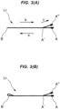
FIG. 3 are explanatory views of laser irradiation positions in the laser welding method. -
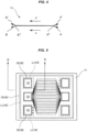
FIG. 4 is an explanatory view of laser irradiation positions in a laser welding method according to another example of the present invention. -
FIG. 5 is a plan view illustrating an example of a fuel-cell cell serving as a workpiece in a laser welding method according to a conventional example. -
FIG. 6 is a cross-sectional view of a principal portion of the fuel-cell cell and is an enlarged cross-sectional view along the D-D line inFIG. 5 . -
FIG. 7 is a plan view illustrating an example of a fuel cell constituent component serving as a workpiece in a laser welding method according to a conventional example. -
FIG. 8 is a cross-sectional view of a principal portion of the fuel cell constituent component and is an enlarged cross-sectional view along the E-E line inFIG. 7 . -
FIG. 9 is a plan view illustrating another example of the fuel cell constituent component serving as a workpiece in the laser welding method according to the conventional example. -
FIG. 10 are process explanatory views of the laser welding method according to the conventional example. -
FIG. 11 is an explanatory view of laser irradiation positions in a laser welding method according to another conventional example. - The present invention contains the following embodiments.
- (1) A separate component (accessory component) is joined by welding to welded separators in which an anode separator and a cathode separator are welded to thereby form a seal line. The welding of the seal line and the welding of the separate component are carried out in the same process (same facility) and, when the separate component is welded to the separators, laser irradiation is performed a plurality of times in the same welding line. It is configured so that the welding lines of a start portion and a termination end of the welding are shifted away from each other when the laser irradiation is performed a plurality of times in the same welding line.
- (2) In the case where the welding of the seal line and the welding of the separate component are carried out in the same process (same facility), when the laser irradiation is performed a plurality of times in the same welding line in welding the separate component to the separators, the welding lines of the start portion and the termination end of the laser irradiation are shifted away from each other so as not to be overlapped. This makes it possible to avoid that the density of the energy (heat input amount) to be emitted to the start portion and the termination end become excessive and to take measures against a defect, such as a hole.
- (3) According to the present invention, by carrying out the welding of the seal line and the welding of the separate component in the same process, the number of processes decreases and the facility decreases, so that a cost reduction can be expected. By avoiding the concentration of the energy density (heat input amount) in the start portion and the termination end of the welding, a defect of a hole does not occur, so that the quality is stabilized.
- Next, examples of the present invention are described according to the drawings.
- As illustrated in
FIGS. 1 and2 , a laser welding method according to this example includes joining a pair offuel cell separators separators accessory component 20, a voltage monitoring component is illustrated. However, the type of the component is not particularly limited and a component for positioning between separators illustrated inFIG. 9 above or the like may be acceptable, for example. In the plan view ofFIG. 1 , the weldedseal 14 is indicated by the dotted line and the rubber seal (rubber seal line) 16 by thegasket 15 is indicated by the solid line. - Moreover, as a method for not performing the welding of the
accessory component 20 and the welding of theseparators separators separators accessory component 20 are performed in the same process using the same laser irradiation device (not illustrated) in the laser welding method according to this example. - The procedure is as follows.
- More specifically, first, the pair of
separators separators seal 14, of theseparators FIG. 2(A) . - Subsequently, as illustrated in
FIGS. 2(B) and 2(C) , theaccessory component 20 is stacked on the pair of weldedseparators separators accessory component 20 are irradiated with a laser beam (second irradiation) to form the welded portion L2 of theaccessory component 20. When theseparators accessory component 20 are welded, the welded portion L2 of theaccessory component 20 is reciprocatingly irradiated with laser along a fixed welding line. Herein, the description "the welded portion L2 of theaccessory component 20 is reciprocatingly irradiated with laser along a fixed welding line" means that the irradiation is performed twice (one reciprocation) along the fixed welding line. However, when the start end and the termination end of the irradiation are set at the same position while overlapping each other on the plane, a state where the density of the energy to be emitted becomes excessively high is caused, so that a defect, such as a hole, occurs in some cases as described above. - Thus, in this example of the present invention, when the laser beam is emitted a plurality of times along the fixed welding line, the irradiation positions of the ends of the irradiation are shifted away from each other so that the irradiation energy can be dispersed. Specifically, when the laser beam is reciprocatingly emitted along the fixed welding line, the irradiation positions of the start end and the termination end of the irradiation are shifted away from each other so that the irradiation energy can be dispersed. A specific procedure is as follows.
- First scanning of second irradiation (forward scanning,
FIG. 2(B) ) - As illustrated in
FIG. 3(A) , when laser is emitted along the fixed welding line from an A point to a B point in the welded portion L2 of theaccessory component 20, the laser is emitted from the A point to the B point (arrow a) with the A point as the start end of the irradiation. - Second scanning of second irradiation (return scanning,
FIG. 2(C) ) - As illustrated in the figure, the laser is continuously emitted from the B point to the A point by returning at the B point (arrow b). However, the direction of the irradiation is changed at an A' point (branched portion) before (immediately before) reaching the A point, whereby a branched line of the welding line is set (arrow c) and an A" point close to the A point but different from the A point is set as the termination end of the irradiation.
- Hence, according to this procedure, the welded portion L2 of the
accessory component 20 can be reciprocatingly irradiated with laser along the fixed welding line and the irradiation energy is dispersed by shifting the irradiation positions of the start end (A point) and the termination end (A" point) of the irradiation when the laser beam is reciprocatingly emitted along the fixed welding line, and therefore a state where the irradiation energy density becomes excessively high in the start end and the termination end of the irradiation is not caused. Hence, the occurrence of a defect, such as a hole, in a workpiece due to the fact that a state where the irradiation energy density becomes excessively high by a plurality of times of laser irradiation is caused can be prevented as expected by the present invention. - When there is a concern that the irradiation energy density increases not only in the start end and the termination end of the irradiation but at a returning portion (B point) of the irradiation, the welding line may be reversed in a U shape or a substantially U shape at the returning portion (B point) of the irradiation as illustrated in
FIG. 3(B) . - Moreover, it is also assumed that a laser beam is emitted a plurality of times in the same direction along the fixed welding line instead of reciprocatingly emitting a laser beam along the fixed welding line as with the example described above. Therefore, in this case, the irradiation positions of the start ends or/and the termination ends of the irradiation are shifted away from each other so that the irradiation energy can be dispersed. A specific procedure is as follows.
- As illustrated in
FIG. 4 , when laser is emitted along the fixed welding line in the welded portion L2 of theaccessory component 20, the A point is set as the start end of the irradiation and the B point is set as the termination end of the irradiation (arrow a). - The second scanning is continuously performed as illustrated in the figure. At this time, an A' point close to the A point but different from the A point is set as the start end of the irradiation and a B' point close to the B point but different from the B point is set as the termination end of the irradiation (arrow a'). The irradiation line of the first scanning and the irradiation line of the second scanning overlap each other on and after an A" point close to the A point and the A' point but different from the A point and the A' point and are branched on and after a B" point close to the B point and the B' point but different from the B point and the B' point.
- Therefore, according to this procedure, the welded portion L2 of the
accessory component 20 can be irradiated with laser a plurality of times along the fixed welding line and, when the laser beam is emitted a plurality of times along the fixed welding line, the irradiation energy is dispersed by shifting the irradiation positions of the start ends (A point and A' point) and the termination ends (B point and B' point) of the irradiation from each other, and therefore a state where the irradiation energy density becomes excessively high in the start ends and the termination ends of the irradiation is not caused. Therefore, the occurrence of a defect, such as a hole, in a workpiece due to the fact that a state where the irradiation energy density becomes excessively high by a plurality of times of laser irradiation is caused can be prevented as expected the present invention. -
- 11,12
- separator (first and second workpieces)
- 13
- manifold
- 14
- welded seal
- 15
- gasket
- 16
- rubber seal
- 17
- hydrogen flow passage
- 18
- oxygen flow passage
- 19
- cooling water flow passage
- 20
- accessory component (third workpiece)
- L1
- separator welded portion
- L2
- accessory component welded portion
Claims (5)
- A laser welding method comprising:welding a plurality of workpieces (11, 12) by irradiating the workpieces (11, 12) in a stacked state with a laser beam,wherein the laser beam is reciprocatingly emitted along a fixed welding line, wherein irradiation positions of a start end and a termination end of the irradiation are shifted away from each other so that irradiation energy can be dispersed,emitting the laser beam from a point A to a point B along the fixed welding line,
characterized byreturning at point B and emitting the laser beam from the point B along the fixed welding line, andchanging the direction of irradiation at a point A' before reaching the point A, whereby a branched line (c) of the welding line is set and a point A" that is different from the point A is set as the termination end of the irradiation,wherein the point A' is between the point A and the point B, and the point A' is different from the point A and the point B. - The laser welding method according to Claim 1 comprising:performing first irradiation of emitting a laser beam so as to weld a first workpiece (11) and a second workpiece (12) along the fixed welding line as first fixed welding line (L1) and second irradiation of emitting a laser beam so as to weld a third workpiece (20) to the first and second workpieces (11, 12) welded by the first irradiation in a same process using a same irradiation device; andreciprocatingly emitting the laser beam along a second fixed welding line (L2) in performing the second irradiation.
- A laser welding method comprising:welding a plurality of workpieces (11, 12) by irradiating the workpieces (11, 12) in a stacked state with a laser beam, whereinthe laser beam is emitted a plurality of times in a same direction along a fixed welding line, wherein irradiation positions of start ends or/and termination ends of the irradiation are shifted away from each other so that irradiation energy can be dispersed,first emitting the laser beam from a point A to a point B along the fixed welding line, wherein the point A is set as the start end of the irradiation and the point B is set as the termination end of the irradiation,characterized bysecond emitting the laser beam from a point A' to a point B' along the fixed welding line,wherein the point A' is different from the point A and is set as the start end of the second emitting, and the point B' is different from the point B and is set as the termination end of the second emitting, wherein the irradiation line of the first emitting and the irradiation line of the second emitting overlap each other on and after a point A" that is different from the point A and the point A' and are branched on and after a point B" that is different from the point B and the point B'.
- The laser welding method according to Claim 3 comprising:performing first irradiation of emitting a laser beam so as to weld a first workpiece (11) and a second workpiece (12) along the fixed welding line as first fixed welding line (L1) and second irradiation of emitting a laser beam so as to weld a third workpiece (20) to the first and the second workpiece (11, 12) welded by the first irradiation in a same process using a same irradiation device; andemitting the laser beam a plurality of times in a same direction along a second fixed welding line in performing the second irradiation.
- The laser welding method according to Claim 3 or 4, whereinthe first and second workpieces (11, 12) are fuel cell separators, andthe third workpiece (20) is an accessory component attached to the fuel cell separator.
Applications Claiming Priority (2)
| Application Number | Priority Date | Filing Date | Title |
|---|---|---|---|
| JP2017032872 | 2017-02-24 | ||
| PCT/JP2018/006162 WO2018155477A1 (en) | 2017-02-24 | 2018-02-21 | Laser welding method |
Publications (4)
| Publication Number | Publication Date |
|---|---|
| EP3587024A1 EP3587024A1 (en) | 2020-01-01 |
| EP3587024A4 EP3587024A4 (en) | 2020-03-11 |
| EP3587024C0 EP3587024C0 (en) | 2025-04-30 |
| EP3587024B1 true EP3587024B1 (en) | 2025-04-30 |
Family
ID=63253295
Family Applications (1)
| Application Number | Title | Priority Date | Filing Date |
|---|---|---|---|
| EP18758380.2A Active EP3587024B1 (en) | 2017-02-24 | 2018-02-21 | Laser welding method |
Country Status (6)
| Country | Link |
|---|---|
| US (1) | US11491579B2 (en) |
| EP (1) | EP3587024B1 (en) |
| JP (1) | JP6735898B2 (en) |
| KR (1) | KR102444098B1 (en) |
| CN (1) | CN110234460B (en) |
| WO (1) | WO2018155477A1 (en) |
Families Citing this family (3)
| Publication number | Priority date | Publication date | Assignee | Title |
|---|---|---|---|---|
| CN111604594A (en) * | 2020-05-27 | 2020-09-01 | 湖北亿纬动力有限公司 | A welding process for a battery cover plate and a battery |
| KR102409185B1 (en) * | 2020-08-21 | 2022-06-16 | 주식회사 보림파워텍 | Bonding method of seperating plate and cell frame for sofc stack |
| CN113146029A (en) * | 2021-04-19 | 2021-07-23 | 山西奥斯腾科技有限责任公司 | Laser head integrating welding, repairing and detecting |
Citations (2)
| Publication number | Priority date | Publication date | Assignee | Title |
|---|---|---|---|---|
| DE102011089146A1 (en) * | 2010-12-27 | 2012-06-28 | Suzuki Motor Corp. | Laser Überlappschweißverfahren |
| DE102010018377B4 (en) * | 2010-04-26 | 2013-09-12 | Labom Meß- und Regeltechnik GmbH | Functional component such as diaphragm seal with a metal foil made of special material, method for welding a metal foil made of special material and laser beam welding device therefor |
Family Cites Families (24)
| Publication number | Priority date | Publication date | Assignee | Title |
|---|---|---|---|---|
| JP2002172484A (en) * | 2000-12-01 | 2002-06-18 | Komatsu Ltd | Joining method |
| US6906281B2 (en) * | 2003-03-03 | 2005-06-14 | Dana Corporation | Method for laser welding of metal |
| US6646225B1 (en) * | 2003-04-02 | 2003-11-11 | General Motors Corporation | Method of joining galvanized steel parts using lasers |
| JP2005106527A (en) * | 2003-09-29 | 2005-04-21 | Toyoda Mach Works Ltd | Pressure sensor and manufacturing method thereof |
| JP5343307B2 (en) * | 2006-05-16 | 2013-11-13 | 日産自動車株式会社 | FUEL CELL STACK, FUEL CELL SEPARATOR, AND METHOD FOR PRODUCING THE SAME |
| JP5239366B2 (en) | 2008-02-05 | 2013-07-17 | 日産自動車株式会社 | Laser welding method, laser welding apparatus, and welding member |
| JP5495118B2 (en) * | 2010-04-28 | 2014-05-21 | スズキ株式会社 | Laser lap welding method of galvanized steel sheet |
| JP2012170989A (en) * | 2011-02-22 | 2012-09-10 | Suzuki Motor Corp | Laser lap welding method |
| JP5880032B2 (en) * | 2011-12-27 | 2016-03-08 | トヨタ自動車株式会社 | Laser welding method |
| KR20140080754A (en) * | 2012-12-17 | 2014-07-01 | 현대자동차주식회사 | Laser welding method |
| JP6194233B2 (en) * | 2013-01-08 | 2017-09-06 | 株式会社ジャパンディスプレイ | Manufacturing method of display device |
| WO2015104781A1 (en) * | 2014-01-10 | 2015-07-16 | パナソニックIpマネジメント株式会社 | Laser welding method and laser welding device |
| WO2015129231A1 (en) | 2014-02-25 | 2015-09-03 | パナソニックIpマネジメント株式会社 | Laser welding method |
| US10195688B2 (en) * | 2015-01-05 | 2019-02-05 | Johnson Controls Technology Company | Laser welding system for a battery module |
| JP6135691B2 (en) * | 2015-02-18 | 2017-05-31 | トヨタ自動車株式会社 | Laser welding method |
| US10835993B2 (en) * | 2015-08-05 | 2020-11-17 | Panasonic Intellectual Property Management Co., Ltd. | Laser welding method |
| US10828720B2 (en) * | 2015-10-13 | 2020-11-10 | The Curators Of The University Of Missouri | Foil-based additive manufacturing system and method |
| US10118249B2 (en) * | 2015-10-15 | 2018-11-06 | GM Global Technology Operations LLC | Laser beam welding with a spiral weld path having a first order of continuity |
| CN108367391B (en) * | 2015-11-06 | 2020-03-20 | 通用汽车环球科技运作有限责任公司 | Laser spot welding of stacked aluminum workpieces |
| US10512986B2 (en) * | 2016-02-15 | 2019-12-24 | Ford Global Technologies, Llc | Laser welding process |
| CN109219498B (en) * | 2016-03-16 | 2021-10-01 | 通用汽车环球科技运作有限责任公司 | Rapid remote laser welding of stacked metal workpieces |
| US10195689B2 (en) * | 2016-07-11 | 2019-02-05 | GM Global Technology Operations LLC | Laser welding of overlapping metal workpieces assisted by varying laser beam parameters |
| US20200114469A1 (en) * | 2017-02-09 | 2020-04-16 | GM Global Technology Operations LLC | Method for laser welding light metal workpieces that include a surface oxide coating |
| US10888955B2 (en) * | 2017-02-28 | 2021-01-12 | GM Global Technology Operations LLC | Avoiding hot cracks during laser welding of a workpiece stack-up assembly of aluminum alloy workpieces |
-
2018
- 2018-02-21 CN CN201880008741.0A patent/CN110234460B/en active Active
- 2018-02-21 EP EP18758380.2A patent/EP3587024B1/en active Active
- 2018-02-21 JP JP2019501367A patent/JP6735898B2/en active Active
- 2018-02-21 WO PCT/JP2018/006162 patent/WO2018155477A1/en not_active Ceased
- 2018-02-21 KR KR1020197023103A patent/KR102444098B1/en active Active
- 2018-02-21 US US16/478,594 patent/US11491579B2/en active Active
Patent Citations (2)
| Publication number | Priority date | Publication date | Assignee | Title |
|---|---|---|---|---|
| DE102010018377B4 (en) * | 2010-04-26 | 2013-09-12 | Labom Meß- und Regeltechnik GmbH | Functional component such as diaphragm seal with a metal foil made of special material, method for welding a metal foil made of special material and laser beam welding device therefor |
| DE102011089146A1 (en) * | 2010-12-27 | 2012-06-28 | Suzuki Motor Corp. | Laser Überlappschweißverfahren |
Also Published As
| Publication number | Publication date |
|---|---|
| US11491579B2 (en) | 2022-11-08 |
| KR20190121756A (en) | 2019-10-28 |
| WO2018155477A1 (en) | 2018-08-30 |
| JPWO2018155477A1 (en) | 2019-11-07 |
| EP3587024C0 (en) | 2025-04-30 |
| KR102444098B1 (en) | 2022-09-15 |
| EP3587024A4 (en) | 2020-03-11 |
| CN110234460B (en) | 2021-06-29 |
| JP6735898B2 (en) | 2020-08-05 |
| US20200030912A1 (en) | 2020-01-30 |
| EP3587024A1 (en) | 2020-01-01 |
| CN110234460A (en) | 2019-09-13 |
Similar Documents
| Publication | Publication Date | Title |
|---|---|---|
| EP3587024B1 (en) | Laser welding method | |
| JP6331079B2 (en) | Laser welding method and laser welding apparatus | |
| JP6045783B2 (en) | Secondary battery and method for manufacturing secondary battery | |
| JP2016030280A (en) | Method and apparatus for laser welding of metal foil | |
| US20120211474A1 (en) | Laser lap welding method | |
| US20250205820A1 (en) | Laser welding method for multi-layer aluminum foil, battery, welding system, and control device | |
| US9054393B2 (en) | Secondary battery and method of manufacturing the same | |
| CN101908652A (en) | Sealed battery and method for manufacturing sealed battery | |
| JP2016207412A (en) | Laser weldment and laser welding quality determination method for battery | |
| SE512240C2 (en) | Ways of joining at least four heat transfer plates to a plate package and plate package | |
| EP4433252A1 (en) | Improvement welding method for laser weld of battery foils stack, welding method, laser processing system, associated computer program product | |
| US20160207139A1 (en) | Resistance spot welding method and welded structure | |
| US12179285B2 (en) | Laser processing method and laser processing device and sealed type battery | |
| US12419131B2 (en) | Photovoltaic module and manufacturing method thereof | |
| CN104289807A (en) | Welding pads and welding methods | |
| KR102522756B1 (en) | Processing apparatus and method using multi lasers | |
| JP2015130275A (en) | Fuel cell cassette and fuel cell stack | |
| CN109366010B (en) | Laser incident angle determining method for T-shaped joint full penetration laser composite welding | |
| CN121816244A (en) | Laser welding method for electric wire | |
| JP4846392B2 (en) | Underwater repair welding method | |
| CN116060765B (en) | Laser welding methods, welding systems, control devices, process products, and batteries | |
| JP2009248184A (en) | Welded joint, and method for producing the same | |
| JP7611112B2 (en) | Manufacturing method of sealed battery | |
| US20120244416A1 (en) | Beam welding of a multi-sheet work stack with a single common welding interface | |
| JP2017131905A (en) | Laminated laser welding method for plated steel sheets |
Legal Events
| Date | Code | Title | Description |
|---|---|---|---|
| STAA | Information on the status of an ep patent application or granted ep patent |
Free format text: STATUS: THE INTERNATIONAL PUBLICATION HAS BEEN MADE |
|
| PUAI | Public reference made under article 153(3) epc to a published international application that has entered the european phase |
Free format text: ORIGINAL CODE: 0009012 |
|
| STAA | Information on the status of an ep patent application or granted ep patent |
Free format text: STATUS: REQUEST FOR EXAMINATION WAS MADE |
|
| 17P | Request for examination filed |
Effective date: 20190708 |
|
| AK | Designated contracting states |
Kind code of ref document: A1 Designated state(s): AL AT BE BG CH CY CZ DE DK EE ES FI FR GB GR HR HU IE IS IT LI LT LU LV MC MK MT NL NO PL PT RO RS SE SI SK SM TR |
|
| AX | Request for extension of the european patent |
Extension state: BA ME |
|
| A4 | Supplementary search report drawn up and despatched |
Effective date: 20200210 |
|
| RIC1 | Information provided on ipc code assigned before grant |
Ipc: B23K 26/21 20140101AFI20200204BHEP Ipc: H01M 8/02 20160101ALI20200204BHEP Ipc: H01M 8/0202 20160101ALI20200204BHEP Ipc: B23K 26/244 20140101ALI20200204BHEP |
|
| DAV | Request for validation of the european patent (deleted) | ||
| DAX | Request for extension of the european patent (deleted) | ||
| STAA | Information on the status of an ep patent application or granted ep patent |
Free format text: STATUS: EXAMINATION IS IN PROGRESS |
|
| 17Q | First examination report despatched |
Effective date: 20220726 |
|
| GRAP | Despatch of communication of intention to grant a patent |
Free format text: ORIGINAL CODE: EPIDOSNIGR1 |
|
| STAA | Information on the status of an ep patent application or granted ep patent |
Free format text: STATUS: GRANT OF PATENT IS INTENDED |
|
| INTG | Intention to grant announced |
Effective date: 20241125 |
|
| GRAS | Grant fee paid |
Free format text: ORIGINAL CODE: EPIDOSNIGR3 |
|
| GRAA | (expected) grant |
Free format text: ORIGINAL CODE: 0009210 |
|
| STAA | Information on the status of an ep patent application or granted ep patent |
Free format text: STATUS: THE PATENT HAS BEEN GRANTED |
|
| AK | Designated contracting states |
Kind code of ref document: B1 Designated state(s): AL AT BE BG CH CY CZ DE DK EE ES FI FR GB GR HR HU IE IS IT LI LT LU LV MC MK MT NL NO PL PT RO RS SE SI SK SM TR |
|
| REG | Reference to a national code |
Ref country code: CH Ref legal event code: EP Ref country code: GB Ref legal event code: FG4D |
|
| REG | Reference to a national code |
Ref country code: DE Ref legal event code: R096 Ref document number: 602018081512 Country of ref document: DE |
|
| REG | Reference to a national code |
Ref country code: IE Ref legal event code: FG4D |
|
| U01 | Request for unitary effect filed |
Effective date: 20250505 |
|
| U07 | Unitary effect registered |
Designated state(s): AT BE BG DE DK EE FI FR IT LT LU LV MT NL PT RO SE SI Effective date: 20250521 |
|
| PG25 | Lapsed in a contracting state [announced via postgrant information from national office to epo] |
Ref country code: ES Free format text: LAPSE BECAUSE OF FAILURE TO SUBMIT A TRANSLATION OF THE DESCRIPTION OR TO PAY THE FEE WITHIN THE PRESCRIBED TIME-LIMIT Effective date: 20250430 |
|
| PG25 | Lapsed in a contracting state [announced via postgrant information from national office to epo] |
Ref country code: NO Free format text: LAPSE BECAUSE OF FAILURE TO SUBMIT A TRANSLATION OF THE DESCRIPTION OR TO PAY THE FEE WITHIN THE PRESCRIBED TIME-LIMIT Effective date: 20250730 Ref country code: GR Free format text: LAPSE BECAUSE OF FAILURE TO SUBMIT A TRANSLATION OF THE DESCRIPTION OR TO PAY THE FEE WITHIN THE PRESCRIBED TIME-LIMIT Effective date: 20250731 |
|
| PG25 | Lapsed in a contracting state [announced via postgrant information from national office to epo] |
Ref country code: PL Free format text: LAPSE BECAUSE OF FAILURE TO SUBMIT A TRANSLATION OF THE DESCRIPTION OR TO PAY THE FEE WITHIN THE PRESCRIBED TIME-LIMIT Effective date: 20250430 |
|
| PG25 | Lapsed in a contracting state [announced via postgrant information from national office to epo] |
Ref country code: HR Free format text: LAPSE BECAUSE OF FAILURE TO SUBMIT A TRANSLATION OF THE DESCRIPTION OR TO PAY THE FEE WITHIN THE PRESCRIBED TIME-LIMIT Effective date: 20250430 |
|
| PG25 | Lapsed in a contracting state [announced via postgrant information from national office to epo] |
Ref country code: RS Free format text: LAPSE BECAUSE OF FAILURE TO SUBMIT A TRANSLATION OF THE DESCRIPTION OR TO PAY THE FEE WITHIN THE PRESCRIBED TIME-LIMIT Effective date: 20250731 |
|
| PG25 | Lapsed in a contracting state [announced via postgrant information from national office to epo] |
Ref country code: IS Free format text: LAPSE BECAUSE OF FAILURE TO SUBMIT A TRANSLATION OF THE DESCRIPTION OR TO PAY THE FEE WITHIN THE PRESCRIBED TIME-LIMIT Effective date: 20250830 |
|
| PG25 | Lapsed in a contracting state [announced via postgrant information from national office to epo] |
Ref country code: SM Free format text: LAPSE BECAUSE OF FAILURE TO SUBMIT A TRANSLATION OF THE DESCRIPTION OR TO PAY THE FEE WITHIN THE PRESCRIBED TIME-LIMIT Effective date: 20250430 |
|
| PG25 | Lapsed in a contracting state [announced via postgrant information from national office to epo] |
Ref country code: CZ Free format text: LAPSE BECAUSE OF FAILURE TO SUBMIT A TRANSLATION OF THE DESCRIPTION OR TO PAY THE FEE WITHIN THE PRESCRIBED TIME-LIMIT Effective date: 20250430 |
|
| PG25 | Lapsed in a contracting state [announced via postgrant information from national office to epo] |
Ref country code: SK Free format text: LAPSE BECAUSE OF FAILURE TO SUBMIT A TRANSLATION OF THE DESCRIPTION OR TO PAY THE FEE WITHIN THE PRESCRIBED TIME-LIMIT Effective date: 20250430 |
|
| U20 | Renewal fee for the european patent with unitary effect paid |
Year of fee payment: 9 Effective date: 20260106 |
|
| PLBE | No opposition filed within time limit |
Free format text: ORIGINAL CODE: 0009261 |
|
| STAA | Information on the status of an ep patent application or granted ep patent |
Free format text: STATUS: NO OPPOSITION FILED WITHIN TIME LIMIT |
|
| REG | Reference to a national code |
Ref country code: CH Ref legal event code: L10 Free format text: ST27 STATUS EVENT CODE: U-0-0-L10-L00 (AS PROVIDED BY THE NATIONAL OFFICE) Effective date: 20260311 |
|
| 26N | No opposition filed |
Effective date: 20260202 |