EP3586898B1 - Bestandteile für medizinischen schlauch - Google Patents
Bestandteile für medizinischen schlauch Download PDFInfo
- Publication number
- EP3586898B1 EP3586898B1 EP19176454.7A EP19176454A EP3586898B1 EP 3586898 B1 EP3586898 B1 EP 3586898B1 EP 19176454 A EP19176454 A EP 19176454A EP 3586898 B1 EP3586898 B1 EP 3586898B1
- Authority
- EP
- European Patent Office
- Prior art keywords
- tube
- component
- passageway
- electrical
- port
- Prior art date
- Legal status (The legal status is an assumption and is not a legal conclusion. Google has not performed a legal analysis and makes no representation as to the accuracy of the status listed.)
- Active
Links
- 230000029058 respiratory gaseous exchange Effects 0.000 claims description 46
- 239000012530 fluid Substances 0.000 claims description 44
- 238000000465 moulding Methods 0.000 claims description 36
- 238000004891 communication Methods 0.000 claims description 29
- 238000000034 method Methods 0.000 claims description 13
- 230000037361 pathway Effects 0.000 claims description 12
- 239000011324 bead Substances 0.000 claims description 8
- 230000014759 maintenance of location Effects 0.000 claims description 7
- 239000007789 gas Substances 0.000 description 67
- 239000000463 material Substances 0.000 description 27
- 230000005494 condensation Effects 0.000 description 11
- 238000009833 condensation Methods 0.000 description 11
- 230000003434 inspiratory effect Effects 0.000 description 9
- XLYOFNOQVPJJNP-UHFFFAOYSA-N water Substances O XLYOFNOQVPJJNP-UHFFFAOYSA-N 0.000 description 8
- 238000004519 manufacturing process Methods 0.000 description 7
- 238000002844 melting Methods 0.000 description 7
- 230000008018 melting Effects 0.000 description 7
- 230000008878 coupling Effects 0.000 description 4
- 238000010168 coupling process Methods 0.000 description 4
- 238000005859 coupling reaction Methods 0.000 description 4
- 238000005476 soldering Methods 0.000 description 4
- 230000015572 biosynthetic process Effects 0.000 description 3
- 230000036512 infertility Effects 0.000 description 3
- 239000010410 layer Substances 0.000 description 3
- 230000001681 protective effect Effects 0.000 description 3
- 230000008901 benefit Effects 0.000 description 2
- 238000006073 displacement reaction Methods 0.000 description 2
- 238000009413 insulation Methods 0.000 description 2
- 239000007788 liquid Substances 0.000 description 2
- 229920006395 saturated elastomer Polymers 0.000 description 2
- 238000007789 sealing Methods 0.000 description 2
- 238000009423 ventilation Methods 0.000 description 2
- 206010011224 Cough Diseases 0.000 description 1
- 210000000683 abdominal cavity Anatomy 0.000 description 1
- 230000002411 adverse Effects 0.000 description 1
- 230000003444 anaesthetic effect Effects 0.000 description 1
- 230000036760 body temperature Effects 0.000 description 1
- 238000004140 cleaning Methods 0.000 description 1
- 230000000694 effects Effects 0.000 description 1
- 230000003028 elevating effect Effects 0.000 description 1
- 238000005538 encapsulation Methods 0.000 description 1
- 238000010438 heat treatment Methods 0.000 description 1
- 238000011065 in-situ storage Methods 0.000 description 1
- 238000002357 laparoscopic surgery Methods 0.000 description 1
- 230000000414 obstructive effect Effects 0.000 description 1
- 239000011241 protective layer Substances 0.000 description 1
- 238000011084 recovery Methods 0.000 description 1
- 230000000241 respiratory effect Effects 0.000 description 1
- 238000002644 respiratory therapy Methods 0.000 description 1
- 230000004044 response Effects 0.000 description 1
- 201000002859 sleep apnea Diseases 0.000 description 1
- 239000000779 smoke Substances 0.000 description 1
- 229910000679 solder Inorganic materials 0.000 description 1
- 238000001356 surgical procedure Methods 0.000 description 1
- 210000001835 viscera Anatomy 0.000 description 1
Images


Classifications
-
- A—HUMAN NECESSITIES
- A61—MEDICAL OR VETERINARY SCIENCE; HYGIENE
- A61M—DEVICES FOR INTRODUCING MEDIA INTO, OR ONTO, THE BODY; DEVICES FOR TRANSDUCING BODY MEDIA OR FOR TAKING MEDIA FROM THE BODY; DEVICES FOR PRODUCING OR ENDING SLEEP OR STUPOR
- A61M16/00—Devices for influencing the respiratory system of patients by gas treatment, e.g. mouth-to-mouth respiration; Tracheal tubes
- A61M16/10—Preparation of respiratory gases or vapours
- A61M16/1075—Preparation of respiratory gases or vapours by influencing the temperature
- A61M16/1095—Preparation of respiratory gases or vapours by influencing the temperature in the connecting tubes
-
- A—HUMAN NECESSITIES
- A61—MEDICAL OR VETERINARY SCIENCE; HYGIENE
- A61M—DEVICES FOR INTRODUCING MEDIA INTO, OR ONTO, THE BODY; DEVICES FOR TRANSDUCING BODY MEDIA OR FOR TAKING MEDIA FROM THE BODY; DEVICES FOR PRODUCING OR ENDING SLEEP OR STUPOR
- A61M16/00—Devices for influencing the respiratory system of patients by gas treatment, e.g. mouth-to-mouth respiration; Tracheal tubes
- A61M16/0003—Accessories therefor, e.g. sensors, vibrators, negative pressure
-
- A—HUMAN NECESSITIES
- A61—MEDICAL OR VETERINARY SCIENCE; HYGIENE
- A61M—DEVICES FOR INTRODUCING MEDIA INTO, OR ONTO, THE BODY; DEVICES FOR TRANSDUCING BODY MEDIA OR FOR TAKING MEDIA FROM THE BODY; DEVICES FOR PRODUCING OR ENDING SLEEP OR STUPOR
- A61M16/00—Devices for influencing the respiratory system of patients by gas treatment, e.g. mouth-to-mouth respiration; Tracheal tubes
- A61M16/0057—Pumps therefor
-
- A—HUMAN NECESSITIES
- A61—MEDICAL OR VETERINARY SCIENCE; HYGIENE
- A61M—DEVICES FOR INTRODUCING MEDIA INTO, OR ONTO, THE BODY; DEVICES FOR TRANSDUCING BODY MEDIA OR FOR TAKING MEDIA FROM THE BODY; DEVICES FOR PRODUCING OR ENDING SLEEP OR STUPOR
- A61M16/00—Devices for influencing the respiratory system of patients by gas treatment, e.g. mouth-to-mouth respiration; Tracheal tubes
- A61M16/06—Respiratory or anaesthetic masks
-
- A—HUMAN NECESSITIES
- A61—MEDICAL OR VETERINARY SCIENCE; HYGIENE
- A61M—DEVICES FOR INTRODUCING MEDIA INTO, OR ONTO, THE BODY; DEVICES FOR TRANSDUCING BODY MEDIA OR FOR TAKING MEDIA FROM THE BODY; DEVICES FOR PRODUCING OR ENDING SLEEP OR STUPOR
- A61M16/00—Devices for influencing the respiratory system of patients by gas treatment, e.g. mouth-to-mouth respiration; Tracheal tubes
- A61M16/08—Bellows; Connecting tubes ; Water traps; Patient circuits
- A61M16/0816—Joints or connectors
- A61M16/0841—Joints or connectors for sampling
-
- A—HUMAN NECESSITIES
- A61—MEDICAL OR VETERINARY SCIENCE; HYGIENE
- A61M—DEVICES FOR INTRODUCING MEDIA INTO, OR ONTO, THE BODY; DEVICES FOR TRANSDUCING BODY MEDIA OR FOR TAKING MEDIA FROM THE BODY; DEVICES FOR PRODUCING OR ENDING SLEEP OR STUPOR
- A61M16/00—Devices for influencing the respiratory system of patients by gas treatment, e.g. mouth-to-mouth respiration; Tracheal tubes
- A61M16/08—Bellows; Connecting tubes ; Water traps; Patient circuits
- A61M16/0875—Connecting tubes
-
- A—HUMAN NECESSITIES
- A61—MEDICAL OR VETERINARY SCIENCE; HYGIENE
- A61M—DEVICES FOR INTRODUCING MEDIA INTO, OR ONTO, THE BODY; DEVICES FOR TRANSDUCING BODY MEDIA OR FOR TAKING MEDIA FROM THE BODY; DEVICES FOR PRODUCING OR ENDING SLEEP OR STUPOR
- A61M16/00—Devices for influencing the respiratory system of patients by gas treatment, e.g. mouth-to-mouth respiration; Tracheal tubes
- A61M16/08—Bellows; Connecting tubes ; Water traps; Patient circuits
- A61M16/0883—Circuit type
-
- A—HUMAN NECESSITIES
- A61—MEDICAL OR VETERINARY SCIENCE; HYGIENE
- A61M—DEVICES FOR INTRODUCING MEDIA INTO, OR ONTO, THE BODY; DEVICES FOR TRANSDUCING BODY MEDIA OR FOR TAKING MEDIA FROM THE BODY; DEVICES FOR PRODUCING OR ENDING SLEEP OR STUPOR
- A61M16/00—Devices for influencing the respiratory system of patients by gas treatment, e.g. mouth-to-mouth respiration; Tracheal tubes
- A61M16/10—Preparation of respiratory gases or vapours
- A61M16/14—Preparation of respiratory gases or vapours by mixing different fluids, one of them being in a liquid phase
- A61M16/16—Devices to humidify the respiration air
Definitions
- the present invention relates to components for medical circuits.
- the invention relates to breathing tubes for use in the inspiratory and/or expiratory limb of a breathing circuit, including heated breathing tubes.
- the invention relates to a tube component for a surgical insufflation system, including a heated insufflator tubes.
- the gases inhaled by a patient preferably are delivered in a condition having humidity near saturation level and at close to body temperature (e.g., usually at a temperature between 33°C and 37°C).
- breathing tubes or medical tubes
- some systems may not necessarily require heaters.
- Condensation or rain-out can form on the inside surfaces of the breathing tubes as the high humidity breathing gases cool and/or come into contact with the relatively cooler breathing tube surface. Breathing gases exhaled by a patient are usually returned fully saturated and flow through an expiratory breathing tube. If the expired gas is allowed to cool as it passes along an expiratory breathing tube, condensation or rain-out may also occur.
- Continuous Positive Airway Pressure (CPAP) systems or positive pressure ventilation systems that provide patients suffering from obstructive sleep apnoea (OSA) with positive pressure breathing gases also use breathing tubes for delivering (or removing) inspiratory (and/or expiratory) gases.
- CPAP Continuous Positive Airway Pressure
- OSA sleep apnoea
- Condensate forming in a breathing tube can be breathed or inhaled by a patient and may lead to coughing fits or other discomfort. Condensation within a breathing tube may also interfere with the performance of connected equipment and ancillary devices and/or various sensors.
- the insufflation gas commonly CO2
- CO2 commonly CO2
- the insufflation gas can become saturated as it picks up moisture from the patient's body cavity.
- the moisture in the gases tends to condense out onto the walls of the medical tubing or discharge limb of the insufflation system.
- the water vapour can also condense on other components of the insufflation system, such as filters for example.
- vapour condensing on the filter and run-off along the limbs (inlet or exhaust) from moisture is highly undesirable.
- water that has condensed on the walls can saturate the filter and cause it to become blocked.
- the blockage potentially causes an increase in back pressure and hinders the ability of the system to clear smoke.
- liquid water in the limbs can run into other connected equipment, which is undesirable.
- US 2008/105257 discloses a conduit for use in a respiratory apparatus.
- a medical tube comprising a tube wall defining a passageway for transportation of gas, and having a first end and a second end (such as, for example, a machine end and a patient end), the passageway providing for fluid communication between the ends, wherein at least one end of the medical tube comprises: a cuff over-moulded about and attaching of one or more first pre-formed component(s), one or more second pre-formed component(s), and at least a portion of the at least one tube end, such that in use, the first pre-formed component or components is in fluid communication with the passageway, the, or each, first pre-formed component configured for fluid connection with a further component(s) of a breathing circuit, and the second pre-formed component or components is receivable of an auxiliary medical tube appliance.
- the first pre-formed component comprises a pneumatic port, the pneumatic port providing for pneumatic connection with the at least one end of the passageway
- the pneumatic port is substantially axially aligned with the passageway.
- the pneumatic port is substantially aligned with the passageway such that pneumatic connection between the port and the passageway is provided.
- the pneumatic port is a tubular body having a longitudinal axis, such as a substantially cylindrical housing.
- the at least one second pre-formed component is attachable to at least a part or parts of the at least one tube end.
- the second pre-formed component comprises one or more locators extending from the component for attachment to at least a part or parts of the tube end.
- the locator(s) is attachable to a section or sections of a wall forming the passageway or the at least one end of the tube.
- the locator(s) is/are a clip or clips.
- the at least one second pre-formed component comprises a port, the port receivable of the auxiliary appliance.
- the auxiliary appliance is a sensor for sensing one or more characteristics of gas in the passageway.
- the at least one second pre-formed component comprises a sensor port, the sensor port receivable of a sensor for sensing one or more characteristics of gas in the passageway.
- the sensor port is arranged such that a sensor located by the sensor port is positioned to be in fluid communication with the passageway and substantially perpendicular to flow of gas in the passageway.
- the sensor receivable by the port senses one or more of gas temperature, relative humidity, gas velocity (or flow rate) of gas in the passageway.
- the senor senses relative humidity.
- the second pre-formed component comprises a sensor port
- the sensor is fluidly connected to or in fluid connection with the passageway.
- the auxiliary appliance is an electrical supply for an electrically powered heater or heaters associated with the passageway of the tube.
- the at least one second pre-formed component comprises is an electrical port, the electrical port receivable of electrical connector for providing an electrical supply to one or more electrically powered heater or heaters associated with the passageway.
- the electrical port is fluidly sealed from communication with the passageway.
- the second pre-formed component is a body comprising at least one locator for attachment to at least a section of a wall forming the passageway or the at least one end of the tube.
- the at least one locator comprises electrical connector(s) for electrically coupling the electrical connector with the one or more electrically powered heater or heaters associated with the passageway.
- the electrical port is configured for providing an electrical connection to the heater or heaters.
- the heater or heaters is/are located substantially within the passageway, or substantially within a wall of the passageway, or substantially about an exterior surface of the passageway.
- the heater or heaters is/are located substantially about an exterior surface of the passageway.
- the heater or heaters is/are a heater source for gas passing through the passageway.
- the heater or heaters is/are one or more heater wires.
- the over-moulded cuff forms a pneumatic seal about the at least one tube end and between the first pre-formed component(s) and the second pre-formed component(s), whilst maintaining fluid connection between the first pre-formed component(s) and the at least one end of the tube and passageway therein.
- the cuff is formed from, or by, a single over-moulding procedure.
- the cuff is directly attached during an over-moulding operation to an exterior surface of the at least one end of the tube.
- the cuff is directly attached to the first pre-formed component(s) and the second pre-formed component(s) during the over-moulding operation.
- an intermediate layer or protective collar or material is positioned between the over-moulded cuff and an exterior wall of the passageway, such as for preventing direct contact between the over-moulded cuff and the exterior wall of the passageway.
- the cuff is formed by a single-step over-moulding operation.
- the cuff is formed of a material having a lower relative melting point than that of the first and second pre-formed component(s), and material forming a wall of the passageway.
- the cuff is formed of a material relatively more pliable than that of the first pre-formed component(s) and/or second pre-formed component(s).
- the second pre-formed component is located longitudinally intermediate of the at least one end of the tube and the first pre-formed component.
- the first pre-formed component is substantially axially aligned with the tube passageway, and/or the first pre-formed component is substantially aligned with the tube passageway such that pneumatic connection between the first pre-formed component and the passageway is provided.
- the first pre-formed component comprises a sensor port and an electrical port as single pre-moulded component.
- the interior of the passageway is of a smooth linear surface.
- the interior of the passageway is devoid of corrugations, convolutions or undulations.
- the tube wall is of a corrugated form.
- the interior surface of the passageway is mechanically and/or chemically cleanable, and/or surfaces in contact with the gas is mechanically and/or chemically cleanable.
- the tube is a reusable medical tube.
- a medical tube comprising a tube wall defining a passageway for transportation of gas, and having a first end and a second end (such as, for example, a machine end and a patient end), the passageway providing for fluid communication between the ends, wherein at least one end of the medical tube comprises:
- the sensor port component is arranged such that a sensor located by the sensor port component is in fluid communication with the passageway and positioned to be substantially perpendicular to flow of gas in the passageway.
- a sensor receivable by the sensor port component is sensing of one or more of gas temperature, relative humidity, gas velocity (or flow rate).
- the senor is fluidly connected to or in fluid connection with the passageway.
- the pre-formed sensor port component comprises at least one locator for attachment to at least a section of a wall forming the passageway or the at least one end of the tube.
- the at least one tube end further comprises a pre-formed electrical port component receivable of an electrical connection for providing an electrical circuit or pathway to one or more electrical appliances associated with the passageway, the cuff being additionally over-moulded of the pre-formed electrical port component.
- the electrical appliance is at least one electrically powered heater associated with the passageway of the tube.
- the heater is located substantially within the passageway, or substantially within a wall of the passageway, or substantially about an exterior surface of the passageway.
- the heater is located substantially about an exterior surface of the passageway.
- the heater is a heat source for gas passing through the passageway.
- the heater is at least one heater wire.
- the pre-formed electrical port component comprises at least one locator for attachment to at least a section of a wall forming the passageway or the at least one end of the tube.
- the at least one locator comprises electrical connector(s) for electrically coupling the electrical connector with one or more electrically powered heater or heaters associated with the passageway.
- the electrical port is fluidly sealed from communication with the passageway.
- the pre-formed sensor port component and pre-formed electrical port component are a single pre-moulded component.
- the over-moulded cuff forms a pneumatic seal about, at least, the at least one tube end and between the pre-formed pneumatic component and the pre-formed sensor port component, whilst maintaining fluid connection between the pre-formed pneumatic port component and the at least one end of the tube and passageway.
- the cuff is directly attached during an over-moulding operation to, at least, an exterior surface of the at least one end of the tube, the pre-formed sensor port and the pre-formed pneumatic port.
- the cuff is formed from, or by, a single over-moulding procedure.
- an intermediate layer or protective collar or material is positioned between, at least, the over-moulded cuff and an exterior wall of the passageway, such as for preventing direct contact between the over-moulded cuff and the exterior wall of the passageway.
- the cuff is formed of a material having a lower relative melting point than that of, at least, the pre-formed pneumatic port component, the pre-formed sensor port component, and material forming a wall of the passageway.
- the cuff is formed of a material relatively more pliable than that of, at least, the pre-formed pneumatic port component and/or the pre-formed sensor port component.
- the pre-formed sensor port component is located longitudinally intermediate of the at least one end and the pre-formed pneumatic port component.
- the pre-formed pneumatic port component is substantially axially aligned with the tube passageway, and/or the pre-formed pneumatic port component is substantially aligned with the tube passageway such that pneumatic connection between the pre-formed pneumatic port component and the passageway is provided.
- the interior of the passageway is of a smooth linear surface.
- the interior of the passageway is devoid of corrugations, convolutions or undulations.
- the wall is of a corrugated form.
- the interior surface of the passageway is mechanically and/or chemically cleanable, and/or surfaces in contact with the gas is mechanically and/or chemically cleanable.
- the tube is a reusable medical tube.
- a medical tube comprising a tube wall defining a passageway for transportation of gas, and having a first end and a second end (such as, for example, a machine end and a patient end), the passageway providing for fluid communication between the ends, wherein at least one end of the medical tube comprises:
- the electrical appliance is at least one electrically powered heater associated with the passageway of the tube.
- the heater is located substantially within the passageway, or substantially within a wall of the passageway, or substantially about an exterior surface of the passageway.
- the heater is located substantially about an exterior surface of the passageway.
- the heater is a heat source for gas passing through the passageway.
- the heater is at least one heater wire.
- the pre-formed electrical port component comprises at least one locator for attachment to at least a section of a wall forming the passageway or the at least one end of the tube.
- the at least one locator comprises electrical connector(s) for electrically coupling the electrical connector with one or more electrically powered heater or heaters associated with the passageway.
- the electrical port is fluidly sealed from communication with the passageway.
- the at least one tube end further comprises a pre-formed sensor port component receivable of a sensor for sensing one or more characteristics of gas in the passageway, the cuff being additionally over-moulded of the pre-formed sensor port component.
- the sensor port component is arranged such that a sensor located by the sensor port component is in fluid communication with the passageway and positioned to be substantially perpendicular to flow of gas in the passageway.
- a sensor receivable by the sensor port component is sensing of one or more of gas temperature, relative humidity, gas velocity (or flow rate).
- the senor is fluidly connected to or in fluid connection with the passageway.
- the pre-formed sensor port component comprises at least one locator for attachment to at least a section of a wall forming the passageway or the at least one end of the tube.
- the sensor port and electrical port are a single pre-moulded component.
- the over-moulded cuff forms a pneumatic seal about, at least, the at least one tube end and between the pre-formed electrical port component and the pre-formed pneumatic port component, whilst maintaining fluid connection between the pneumatic port and the at least one end of the tube and passageway.
- the cuff is directly attached during an over-moulding operation to an exterior surface of the at least one end of the tube.
- the cuff is directly attached to, at least, the pre-formed pneumatic port component, pre-formed electrical port component during an over-moulding procedure.
- the cuff is formed from or by a single-step over-moulding procedure.
- the pre-formed pneumatic port component provides for pneumatic connection with the at least one end of the passageway.
- the pre-formed pneumatic port component is substantially axially aligned with the tube passageway and/or wherein the pre-formed pneumatic port component is substantially aligned with the tube passageway such that pneumatic connection between the pre-formed pneumatic port component and the passageway is provided.
- the cuff is formed of a material having a lower relative melting point than that of, at least, the pneumatic port component, electrical port component, and passageway.
- the cuff is formed of a material that is relatively more pliable that that of, at least, the pneumatic port component, electrical port component, and passageway.
- the interior of the passageway is of a smooth linear surface.
- the interior of the passageway is devoid of corrugations, convolutions or undulations.
- the wall is of a corrugated form.
- the interior surface of the passageway is mechanically and/or chemically cleanable, and/or surfaces in contact with the gas is mechanically and/or chemically cleanable.
- the tube is a reusable medical tube.
- a method for fabricating a medical tube comprising:
- the at least one end of the tube is positioned in a tube receiving mould position, the first pre-formed component(s) is/are positioned in first pre-formed component receiving mould position, and the second pre-formed component(s) is/are positioned in a second pre-formed component receiving mould position, such that, the cuff is formed by over-moulding a moulding material about each of the pre-formed components and at least a portion of the at least one end of the tube.
- the first pre-formed component is a pneumatic port, the pneumatic port providing for pneumatic connection with the at least one end of the passageway.
- the pneumatic port aligning substantially axially with the tube passageway.
- the pneumatic port aligning substantially with the tube passageway such that pneumatic connection between the port and the passageway is provided.
- the pneumatic port is a tubular body having a longitudinal axis, such as a substantially cylindrical housing.
- the at least one second pre-formed appliance component is attachable to at least a part or parts of the at least one tube end.
- the second pre-formed component is attachable by one or more locators extending from the component.
- the locator(s) is/are a clip or clips.
- the locator(s) is attachable to a section or sections of a wall forming the passageway and the at least one end of the tube.
- the second pre-formed component is a body comprising at least one locator for attachment to at least a section of a wall forming the passageway and the at least one end of the tube.
- the at least one locator comprises electrical connector(s) for electrically coupling an electrical appliance receivable by the second pre-formed component with one or more electrical appliances associated with the conduit or passageway.
- At least one second pre-formed appliance component comprises a sensor port, the sensor port receivable of a sensor for sensing one or more characteristics of gas in the passageway.
- the sensor port is arranged such that a sensor located by the sensor port is positioned to be substantially perpendicular to flow of gas in the passageway.
- a sensor receivable by the sensor port component is sensing of one or more of gas temperature, relative humidity, gas velocity (or flow rate).
- At least one second pre-formed appliance component is an electrical port receivable of an electrical appliance connection for providing an electrical circuit or pathway to one or more electrical appliances associated with the passageway.
- the electrical port is configured for providing an electrical connection to at least a heater wire.
- the heater wire is located substantially within the passageway, or substantially within a wall of the passageway, or substantially about an exterior surface of the passageway.
- the heater wire is located substantially about an exterior surface of the passageway.
- the heater wire is a heater source for gas passing through the passageway.
- the electrical appliance associated with the passageway is electrically connected to or with the electrical port prior to the over-moulding.
- the heater wire is electrically connected to or with the electrical port prior to the over-moulding in the mould.
- the heater wire is soldered to electrical terminals of the electrical port.
- the interior of the passageway is of a smooth linear surface.
- the interior of the passageway is devoid of corrugations, convolutions or undulations.
- the interior of the passageway is capable of being mechanically and/or chemically cleaned.
- the over-moulded cuff forms a pneumatic seal about the at least one tube end and between the first pre-formed component(s) and the second pre-formed component(s), whilst maintaining fluid connection between the first pre-formed component(s) and the at least one end of the tube and passageway therein.
- the cuff is formed from, or by, a single over-moulding procedure.
- the cuff is directly attached during an over-moulding operation to an exterior surface of the at least one end of the tube.
- the cuff is directly attached to the first pre-formed component(s) and the second pre-formed component(s) during the over-moulding operation.
- the cuff is formed by a single-step over-moulding operation.
- the cuff is formed of a material having a lower melting point than that of the first and second pre-formed component(s), and material forming a wall of the passageway.
- the cuff is formed of a material more pliable than that of the first pre-formed component(s) and/or second pre-formed component(s).
- the second pre-formed component is located longitudinally intermediate of the at least one end and the first pre-formed component.
- the first pre-formed component comprises a sensor port and an electrical port as single pre-moulded component.
- such a second pre-formed component provides for an electrical port and/or a sensor port, wherein optionally at least a portion of the component attaches to the tube by retention of a part of the tube end (e.g., a bead, rib, portion of a tube wall, or combinations of these) and the component.
- a part of the tube end e.g., a bead, rib, portion of a tube wall, or combinations of these
- the component comprises a first part housing an electrical port and/or a sensor port and a second part configured to enclose a rear surface of the electrical port and/or sensor port part.
- the rear surface is provided for electrical connection between the electrical terminals of an electrical port and a heater wire(s) and/or sensor wire(s) or other electrical or sensor components carried by the tube.
- the first part or the second part comprises a channel or a recess or pathway or shaped channel region for heater wire(s) and/or sensor wire(s) extending carried by the tube extending from a tube part thereof to the rear surface for electrical connection to the electrical terminals.
- the one or more protrusions and one or more complimentary recesses are provided upon the first and second parts allowing such parts to fit together. More preferably, such a fit is a snap-fit or a friction-fit configuration.
- the first and second parts are provided with a folding region or a thinned region capable of folding or being folded, such that the first and second parts are provided as a single part, and such parts are able to be fitted together.
- said component provides a housing or encasing for electrical connections between electrical terminals and electrical components carried by the tube.
- at least a part of the electrical port terminals provide for electrical connection to heater wire(s) (and/or sensor wire(s)) provided associated with the tube
- the component 206 provides for a secure retention between the component and at least a part or parts of the end of the tube.
- the terms “medical circuit” and “breathing circuit” are used to indicate the general field of the invention. It is to be understood that a “circuit” is intended to include open circuits, which do not form a complete closed circuit.
- CPAP systems typically consist of a single inspiratory breathing tube between the blower and the patient interface.
- the term “breathing circuit” is intended to include such “open circuits.”
- the term “medical circuit” is intended to include both breathing circuits and insufflation circuits (which are also typically “open”).
- the term “medical tubing” is intended to be read broadly and as flexible tubing suitable for use in the type of medical circuits described above connecting between components of a medical circuit and providing a low resistance gases pathway between components of a medical circuit.
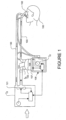
- a humidified ventilation system in which a patient 100 is receiving humidified and pressurised gases through a patient interface 102 connected to a humidified gases transportation pathway or inspiratory breathing tube 103.
- the patient interface 102 may take the form of a nasal mask, oral mask, oronasal mask, nasal prongs, endotracheal tube or full-face mask, etc.
- the inspiratory tube 103 is connected to an outlet 104 of a humidification chamber 105, which contains a volume of water 106.
- the inspiratory tube 103 may include a heater or heater wires (not shown) that heat the humidified gases within the tube to reduce the formation of condensation.
- the humidification chamber 105 is heated by a heater plate 107 of a humidifier base 108.
- the humidifier base 108 can be connected to an electronic controller, which may comprise a microprocessor-based controller executing computer software commands stored in associated memory.
- the controller determines when (or to what level) to energise the heater plate 107 to heat the water 106 within the humidification chamber 105.
- a flow of gases for example air
- a gases supply or ventilator 115 which flow of gases enters the chamber 105 through an inlet 116.
- Exhaled gases from the patient's mouth are returned to the ventilator through a return expiratory breathing tube 130, which tube 130 may also include a heater or heater wires (not shown) that heat the humidified gases within the expiratory breathing tube 130 to reduce the formation of condensation.
- the medical tubing for example, the inspiratory and/or expiratory breathing tubes 103,130
- the medical tubing is: (1) substantially resistant to crushing; (2) substantially resistant to restrictions in flow when bent (increased resistance to flow ⁇ 50% when bent around a 1 inch cylinder); (3) substantially resistant to kinking; (4) substantially resistant to changes in length/volume under fluctuating internal pressure (i.e., resistant to compliance); (5) substantially resistant to leaking (i.e., leakage of ⁇ 25ml/min @6kPa); (6) low in flow resistance (i.e., an increase in pressure @ max. rated flow ⁇ 0.2kPa); (7) substantially electrically safe (i.e., sparks minimized or eliminated in the tubing during use); and/or (8) of a single lumen design.
- a medical tube 200 comprising a tube wall 201 defining a passageway 203 for transportation of gas, and having a first end and a second end (such as, for example, a machine end and a patient end).
- the passageway 203 provides for fluid communication between the ends.
- a cuff 204 over-moulded about and attaching of one or more first pre-formed component(s) 205, one or more second pre-formed component(s) 206, and at least a portion of the at least one tube end 202.
- the cuff 204 is formed such that, in use, the first pre-formed component or components 205 is in fluid communication with the passageway 203, the one or more first pre-formed component 205 being configured for fluid connection with a further component(s) of a breathing circuit, and the second pre-formed component 206 being receivable of an auxiliary medical tube appliance (not shown).
- the one or more first pre-formed component 205 can be formed or configured such that it may comply or be fittingly engageable with those connectors or fittings as required to comply with ISO 5356-1:2004 for 22mm tapered connections.
- FIG. 2 An end 202 of a conduit or medical tube 200 according to one embodiment of the invention is illustrated in Figure 2 .
- the medical tube 200 comprises a tube wall 201 defining the passageway (or lumen) 203 for transportation of breathing gases along the tube from a first end to a second end of the tube wall, for example from a machine end of the medical tube in fluid communication with a blower unit to a patient end of the conduit in fluid communication with a face mask or other patient interface.
- One or both ends of the conduit 200 may be configured as illustrated in Figure 2 .
- the first pre-formed component 205 provides for a pneumatic port 207 in fluid communication with the passageway 203.
- the first pre-formed component 205 can be shaped or configured for connection with a further component of a breathing a circuit, for example to a humidification device (e.g. outlet from humidifier chamber) or a patient interface (e.g. mask or nasal cannula), or other connecting device.
- a pre-formed component 205 is pre-formed (or pre-moulded) prior to being over-moulded with the cuff 204.
- the first pre-formed component 205 for example, can be formed from a relatively rigid material for ease of connection with a further component of a breathing a circuit, including insufflator circuits, or alternatively for durability with re-use.
- the pneumatic port 207 preferably is substantially axially aligned with the passageway 203, or substantially aligned with the passageway 203 or tube wall 201, such that pneumatic (or fluid) connection between the pneumatic port 207 and the passageway 203 is facilitated.
- the pneumatic port 207 can be a tubular body having a longitudinal axis, such as a substantially cylindrical housing.
- the tube end 202 further comprises a second pre-formed component 206.
- a second pre-formed component 206 is adapted to receive an auxiliary medical tube appliance.
- the second preformed component 206 is a port for receiving an auxiliary medical tube appliance (not shown).
- the auxiliary medical tube appliance can be a sensor (not shown) for sensing one or more characteristics of gas in the passageway.
- at least one of the second pre-formed components 206 comprises a sensor port 209 for receiving such a sensor.
- the second pre-formed component 206 can be formed from a relatively rigid material for ease of connection with an auxiliary medical tube appliance, or alternatively for durability with re-use.
- the sensor port 209 is configured to position a sensor substantially perpendicular to a flow of gas in the passageway 203.
- the sensor received by the sensor port 209 advantageously may sense one or more characteristics of gas or gas flow in the passageway 203 (e.g., one or more of gas temperature, relative humidity, gas velocity, gas flow rate).
- the auxiliary medical tube appliance is a temperature sensor that fittingly engages (e.g., fluidly seals) with the port 209.
- Figures 2-5 illustrate embodiments of the tubes 200 comprising embodiments of the sensor port 209.
- Figures 2 and 4 illustrate configurations that additionally include an electrical port 210.
- a plug or cap 212 can provided for fluidly sealing the port 209, although the plug or cap 212 could be appropriately shaped or configured for sealing the electrical port 210. In some configurations, at least one plug or cap 212 can be provided for both the port 209 and the electrical port 210.
- the auxiliary medical appliance can be an electrical supply (e.g. a plug or electrical terminals) that is used to electrically connect a power source to the medical tube.
- at least one of the second pre-formed components 206 can comprise an electrical port 210 that is adapted to receive an electrical connector, providing an electrical supply to one or more electrically powered heater or heaters associated with the passageway 203.
- a heater or heaters is/are located substantially within the passageway 203, or substantially within a wall 201 of the passageway 203, or substantially about an exterior surface of the passageway or tube wall 201.
- Such heaters may be one or more heater wires.
- Such electrically powered heaters may be electrically connected to terminals at the electrical port 210 via soldering of connections, or provision of suitable insulation displacement connector systems.
- Figures 2 and 4 illustrate embodiments of the tube 200 comprising a sensor port 209 and an electrical port 210. However, it will be appreciated an embodiment similar to that of any of the figures, including Figures 3 and 5 , may be provided but where there is only an electrical port 210 and no sensor port 209 provided.
- the electrical port 210 preferably comprises electrical terminals, such as a set of pins 213 similar to those shown in port 210 of Figure 8 .
- the electrical terminal connections of the port 210 can be electrically connected to, for example, the heater wires 211 for completing an electrical circuit pathway.
- Figures 9A and 9B illustrate one example of electrical connections made between the heater wires 211 and the electrical terminals (e.g., pins 213) of the port 210.
- Figures 9A and 9B further illustrate an embodiment of a locator 208 associated with the electrical port 210 attached to a region of one end of the tube 200.
- the electrical port 210 as shown by Figures 9A and 9B , may include a plastic hinge 214 (not specifically detailed) that allows the locator 208 and the port 210 to be closed such that subsequent over-moulding by a cuff is facilitated to provide for an assembled tube 200 as shown by the other figures.
- the second pre-formed component 206 such a component is attachable to at least a part or parts of the at least one tube wall end.
- one or more locators 208 may extend from the second pre-formed component 206 for attachment to at least a part or parts of the tube end.
- the locator(s) 208 are attachable to a section or sections of a wall forming the passageway and the at least one end of the tube.
- the locators can be of a different form, such as that shown in Figures 9A and 9B , for example but without limitation.
- the heater wires 211 contained within a helical bead extending about the outer surface of the conduit are exposed and are electrically terminated or connected to the electrical port 210.
- Figures 4 and 5 illustrate the tube 200 comprising a helical bead containing the electrically powered heater wire 211.
- the at least one locator 208 of the second pre-formed component 206 can be employed for positioning the component in place relative to the end of the tube prior to over-moulding of the cuff 204.
- the second pre-formed component 206 is located longitudinally intermediate of the at least one end and the first pre-formed component 205.
- Such locators 208 may be a clip or clips for attaching or connecting to an end of the tube wall. However, such locators 208 may additionally provide further functionality.
- the one or more of the locators 208 may electrically connect the electrically powered heater or heaters associated with the passageway 203.
- the second pre-formed component 206 with an electrical port 210 allow for electrical connection of a power source to the heaters (e.g. heater wires).
- the electrical connection can be by way of soldering of heater wires to the electrical terminal (e.g. pins in port 210), or for example by insulation displacement connection of the locator clips to the heater wires, thereby creating an electrical pathway to the electrical terminal of the port 210.
- the electrical port 210 is configured for providing electrical connection between an auxiliary medical appliance and those parts of the medical tube 200 needing electrical power for operation.
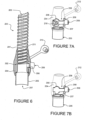
- Figures 10a and 10b illustrate an embodiment of the present invention, of how a second pre-formed component 206 may configured.
- a component 206 in these figures is shown, for the sake of clarity, without the optional sensor port 206 or the first pre-formed component 205, or the over-moulded cuff 204.
- the component 206 attaches to at least a portion of parts of the at least one tube end 202.
- Such a portion of parts that the component 206 attaches to may be a portion of a bead or rib or corrugated portion of a tube 201.
- An optional sensor port may be provided by such a component 206.
- the component 206 may attach to a bead 215.
- a bead 215 can encapsulate or house or locate a heater or heater wire or other electrical components (whether singular components or plural components) requiring electrical connection with an auxiliary medical tube appliance which can be connected to the electrical terminals 210 (not specifically shown in figures 10a or 10b , but shown in figures 2, 4 , 7A , 8 by way of example).
- the component 206 is formed in a manner that allows the component to fold over upon itself. Such folding may be about a thinned mid-line or other region 216 of the component 206.
- the component 206 may advantageously provide for an appropriately shaped channel region 217 allowing for a pathway of electrical heaters or sensor wires or other electrical components extending from the end of the tube to the electrical terminals of the component 206.
- a latching arrangement comprising a protrusion 218 and a complimentary receptacle 219 for the protrusion may be provided for retaining the component in a folded arrangement. This may be provided in the form of a snap-fit or friction-fit positioning of the protrusion into the receptacle. It will however be appreciated that other forms of retention of the component in a folded arrangement may be contemplated.
- the component 206 provides for a secure retention between the component and at least a part or parts of the end of the tube.
- the component 206 as shown by figure 10a and 10b may additionally provide for an improved security or latching region about electrical connections or solder joints, thereby protecting such connections or joints from impact or potential for fracture. Such a component 206 may facilitate improved stability of attachment or grip to the end of the tube 202.
- the component 206 is in an "open" position where the first part (e.g., the part housing the electrical port 210 or any sensor port (not shown)) of the component and its rear surface is exposed, showing electrical connection between heater wires extending from a tube bead and connecting to the electrical terminals of electrical port 210.
- the second part of the component e.g., the part shown in this embodiment as having the channel 217 and the protrusion 218, has the folding region or thinned region 216 allowing folding of the first and second parts together for retention of the component 206 to the tube end.
- Figure 10b shows the component 206, according to the present invention, where the first and second parts are in a closed configuration and the component 206 is in retention of the tube.
- the protrusion 218 is received by the recess 219, such receipt providing for holding the component in its closed position.
- the second pre-formed component 206 is adapted to receive auxiliary medical appliances, where both of a sensor port 209 and an electrical port 210 are provided.
- a component 206 is a single component or piece.
- the cuff 204 is over-moulded about and attaches to the first pre-formed component 205 and the second pre-formed component 206 and the at least one end 202 of the medical tube's wall 201 so that the first preformed component 205 is in fluid communication with the passageway 203.
- the cuff 204 is over-moulded in a single over-moulding operation or procedure. That is, there is no requirement for multiple moulding stages or sequences. Furthermore, there is no need for a protective layer, material or other shroud to cover or provide protection to the medical tube (particularly the wall of the tube) from the over-moulding material. Problems encountered in the past with over-moulding have included burn-through or melting of tube walls when cuff material is applied in a moulding condition (e.g. melt state).
- the cuff 204 advantageously is formed of a material relatively more pliable than that of the first pre-formed component(s) and/or second pre-formed component(s), or may be of a material having a lower relative melting point than that of the first and second pre-formed component(s) 205, 206, and the material forming the tube wall 201.
- the cuff 204 can be directly attached during an over-moulding operation to an exterior surface of at least one end of the tube wall.
- directly attached means the conduit end 200 does not comprise any intermediate layer or protective collar or material positioned between the over-moulded cuff 204 and an exterior surface of the tube wall 201, such as for preventing direct contact between the over-moulded cuff and the exterior surface of the tube wall.
- the over-moulded cuff 204 forms a pneumatic seal about at least one tube wall end and between the first pre-formed component(s) 205 and the second pre-formed component(s) 206, whilst maintaining fluid connection between the first pre-formed component(s) 205 and the at least one end 202 and passageway 204 of the medical tube 200.
- the cuff 204 can optionally include one or more caps or plugs 212.
- a cap or plug 212 can be utilised to cap or plug a sensor port 209 or an electrical port 210 when either (or both) are not in use, or do not have an auxiliary appliance in-situ.
- Such a plug 212 may further ensure a pneumatic seal is provided between the passageway and the pneumatic port 207 or end of the first pre-formed component 205 when one or more of the ports 209, 210 is provided but no auxiliary appliance is positioned therein.
- An alternative conduit end to that illustrated in Figure 2 is an end that comprises more than one first pre-formed component 205 (e.g., may have two or more pneumatic ports) or more than one second pre-formed component 206 (e.g., may have separate second pre-formed components 206 providing for separate sensor port 209 and separate electrical port 210).
- first pre-formed component 205 e.g., may have two or more pneumatic ports
- second pre-formed component 206 e.g., may have separate second pre-formed components 206 providing for separate sensor port 209 and separate electrical port 210.
- the interior wall surface of the medical tube may be substantially smooth or of an undefined shape.
- the tube wall 201 can comprise a rib formed in or on the tube wall of the conduit.
- the rib can be helically disposed along the length of the tube wall 201.
- Separate ribs may be formed spaced apart along the length of the tube wall.
- a separate rib may be formed around a circumference of the tub wall and may be linearly spaced apart from further separate ribs.
- Such ribs may be utilised for structural strength purposes of the medical tube, or may encapsulate, overlie or surround an electrically powered heater, for example a heater wire, or may provide both a heater encapsulation and a tube strength benefit.
- the interior wall surface of the passageway may be a smooth surface.
- the interior of the passageway may be devoid of corrugations, convolutions or undulations. Such a configuration may assist with the ability to clean medical tubing for re-use.
- the passageway of the tube wall comprises a corrugated form, although this may be less preferable for ease of cleaning for subsequent re-use.
- the medical tube, or at least the interior surface of the passageway of the medical tube advantageously is mechanically and/or chemically cleanable.
- at least those surfaces of the medical tube that are in contact with the gas i.e., inspiratory or expiratory limbs
- the medical tube 200 comprises a tube wall defining a passageway 203 for transportation of gas, and having a first end and a second end (such as, for example, a machine end and a patient end).
- the passageway 203 provides for fluid communication between the ends and at least one end 202 of the medical tube 200 comprises a pre-formed pneumatic port component in fluid communication with the passageway.
- the component can be configured for fluid connection with a further component(s) of a breathing circuit.
- a pre-formed sensor port component is receivable of a sensor for sensing one or more characteristics of gas in the passageway 203 and a cuff 204 is over-moulded about and thereby connects the pneumatic port component, the sensor port component and at least a portion of the tube end.
- At least one tube end further comprises a pre-formed electrical port component receivable of an electrical connection for providing an electrical circuit or pathway to one or more electrical appliances associated with the passageway, the cuff being additionally over-moulded over the pre-formed electrical port component.
- the medical tube 200 comprises a tube wall defining a passageway for transportation of gas and having a first end and a second end (such as, for example, a machine end and a patient end).
- the passageway provides for fluid communication between the ends and at least one end of the medical tube comprises a pre-formed pneumatic port connector component in fluid communication with the passageway.
- the connector component can be configured for fluid connection with a further component(s) of a breathing circuit.
- a pre-formed electrical port component can be receivable of an electrical connection for providing an electrical circuit or pathway to one or more electrical appliances associated with the passageway.
- a cuff can be over-moulded about and can thereby connect the pneumatic port component, the electrical port component and at least a portion of the tube end.
- at least one tube end further comprises a pre-formed sensor port component receivable of a sensor for sensing one or more characteristics of gas in the passageway, the cuff being additionally over-moulded over the pre-formed sensor port component.
- the pneumatic port is generally as shown by the first pre-formed component 205 as previously described; the sensor port component is generally as shown by the second pre-formed component part 209 as previously described; and the electrical port component is generally as shown by the second pre-formed component part 210.
- an electrical port 210 and a sensor port 209 may each be optionally included in such arrangements of medical tubes 200.
- an electrical port is provided, various forms of electrical connection and electrically powered heater or heaters, as previously described, can be implemented.
- a sensor port is provided, various forms of the sensor port and sensor positioning, as previously described, can be implemented.
- one such method for fabrication comprises one or more of the following steps:
- the steps also may optionally provide for the electrical port to be located on the outside of the cuff and electrically connected to the tube's heater wires such that there are no bare heater wires on the interior surface of the tube.
- the electrical port may be located on the outside of the cuff and electrically connected to the tube's heater wires such that there are no bare heater wires on the interior surface of the tube.
- Such a fabrication can be performed using a mould receivable of the at least one tube end 202, as well as the various pre-formed components (205, 206).
- a moulding die For example, in a moulding die:
- Tube materials may be those chosen to be suitable for re-use applications, for durability, for hygiene or sterility purposes, as well as for complying with standards governing breathing tubes.
Claims (13)
- Medizinischer Schlauch, (200) umfassend:Eine Schlauchwand (201), die einen Durchgang (203) zum Transport von Gas definiert, und ein erstes Ende und ein zweites Ende aufweist, wobei der Durchgang (203) für Fluid-Kommunikation zwischen den Enden sorgt,wobei zumindest ein Ende des medizinischen Schlauchs (200) umfasst:Eine Manschette (204), die um ein oder mehrere erste vorgeformte Bestandteil(e) (205), ein oder mehrere vorgeformte Bestandteil(e) (206) und zumindest einen Abschnitt des zumindest einen Schlauchendes (202) gespritzt und daran befestigt ist,sodass im Gebrauch der erste vorgeformte Bestandteil (205) oder Bestandteile in Fluid-Kommunikation mit dem Durchgang (203) ist/sind, das, oder jedes, erste vorgeformte Bestandteil (205) für Fluid-Verbindung mit einem weiteren Bestandteil(en) eines Atmungskreislaufs ausgelegt ist,wobei zumindest ein zweites vorgeformte Bestandteil (206) einen Sensoranschluss (209) zur Aufnahme eines Sensors zum Abtasten einer oder mehrere Charakteristiken von Gas im Durchgang (203) umfasst und/oderwobei das zumindest eine zweite vorgeformte Bestandteil (206) einen elektrischen Anschluss (210) zur Aufnahme eines elektrischen Steckverbinders zur Bereitstellung einer elektrischen Versorgung zum einen oder zu den mehreren elektrisch betriebenen Heizgerät(en) umfasst, das/die mit dem Durchgang (203) verbunden ist/sind,wobei sich das/die zweite(n) vorgeformte(n) Bestandteil (206) oder Bestandteile an zumindest einen Teil oder Teile des zumindest einen Schlauchendes (202) befestigen lässt/lassen,dadurch gekennzeichnet, dass das/die zweite(n) vorgeformte(n) Bestandteil (206) oder Bestandteile ein erstes Teilgehäuse des elektrischen Anschlusses (210) und/oder einen Sensoranschluss (209) umfasst und ein zweiter Teil ausgelegt ist, eine hintere Oberfläche des ersten Teils zu umschließen, undwobei die ersten und zweiten Teile mit einem Faltbereich oder einem verdünnten Bereich (216) versehen sind, die so faltbar oder gefaltet werden können, dass die ersten und zweiten Teile als ein Einzelteil bereitgestellt werden und sich die ersten und zweiten Teile miteinander verbinden lassen.
- Medizinischer Schlauch wie in Anspruch 1 beansprucht, wobei die hintere Oberfläche für elektrische Verbindung zwischen elektrischen Klemmen des elektrischen Anschlusses (210) und einem Heizdraht(-drähten) und/oder dem Sensoranschluss (209) und einem Sensordraht(-drähten) oder anderen elektrischen oder Sensorbestandteilen bereitgestellt ist, die vom medizinischen Schlauch (200) getragen werden.
- Medizinischer Schlauch wie in Anspruch 1 oder Anspruch 2 beansprucht, wobei der erste Teil oder der zweite Teil, oder sowohl die ersten als auch zweiten Teile, einen Kanal (217) oder eine Vertiefung oder einen Weg oder einen geformten Kanalbereich für den/die Heizdraht(-drähte) und/oder Sensordraht(-drähte) umfasst/umfassen, die vom medizinischen Schlauch (200) getragen werden, die sich aus einem medizinischen Schlauchteil davon zur hinteren Oberfläche für elektrischen Anschluss an elektrischen Klemmen erstrecken.
- Medizinischer Schlauch wie in irgendeinem der Ansprüche 1 bis 3, wobei ein Vorsprung oder mehrere Vorsprünge und eine oder mehrere komplementäre Vertiefung(en) auf den ersten und zweiten Teilen bereitgestellt sind, welche solchen Teilen ermöglicht bzw. ermöglichen zusammenzupassen; optional wobei die ersten und zweiten Teile in einer "Snap-fit"- oder Reibungspassung-Konfiguration zusammenpassen.
- Medizinischer Schlauch wie in irgendeinem der Ansprüche 1 bis 4 beansprucht, wobei der elektrische Anschluss (210) elektrische Klemmen umfasst und zumindest ein Teil der elektrischen Anschlussklemmen für elektrischen Anschluss zum/zu den Heizdraht (-drähten und/oder Sensordraht (-drähten) sorgt, die mit dem medizinischen Schlauch bereitgestellt bzw. damit verbunden sind.
- Medizinischer Schlauch wie in irgendeinem der Ansprüche 1 bis 5 beansprucht, wobei ein Abschnitt des zweiten vorgeformten Bestandteils (206) am medizinischen Schlauch durch Beibehaltung eines Teils des Schlauchendes (202), beispielsweise einer Wulst, Rippe, eines Abschnitts der Schlauchwand oder Kombinationen davon und dem zweiten vorgeformten Bestandteil angebracht wird.
- Medizinischer Schlauch wie in irgendeinem der Ansprüche 1 bis 6 beansprucht, wobei das zweite vorgeformte Bestandteil (206) einen oder mehrere Positionierer umfasst, der/die sich aus dem Bestandteil zur Anbringung an zumindest einen Teil oder Teile des Schlauchendes erstrecken.
- Medizinischer Schlauch wie in Anspruch 7 beansprucht, wobei der/die Positionierer ein Clip oder Clips ist/sind.
- Medizinischer Schlauch wie in irgendeinem der Ansprüche 1 bis 8 beansprucht,
wobei wo das zweite vorgeformte Bestandteil (206) den elektrischen Anschluss (210) umfasst, der elektrische Anschluss von Kommunikation mit dem Durchgang (203) fluidisch abgedichtet ist. - Medizinischer Schlauch wie in irgendeinem der Ansprüche 1 bis 9 beansprucht, wobei wo das zweite vorgeformte Bestandteil (206) den elektrischen Anschluss (210) umfasst, sich das Heizgerät oder die Heizgeräte wesentlich innerhalb des Durchgangs (203) oder wesentlich innerhalb einer Wand des Durchgangs (203) oder wesentlich um eine Außenfläche des Durchgangs (203) herum befindet/befinden.
- Medizinischer Schlauch wie in irgendeinem der Ansprüche 1 bis 10 beansprucht, wobei die darüber geformte Manschette (204) eine pneumatische Dichtung über das zumindest eine Schlauchende (202) und zwischen dem/den ersten vorgeformten Bestandteil(en) (205) und dem/den zweiten vorgeformten Bestandteil(en) (206) bildet, während Fluid-Verbindung zwischen dem/den ersten vorgeformten Bestandteil(e) und dem zumindest einem Ende des medizinischen Schlauchs und dem darin befindlichen Durchgang beibehalten wird.
- Medizinischer Schlauch wie in irgendeinem der Ansprüche 1 bis 11 beansprucht, wobei die Manschette (204) von oder durch einen einzelnen Überspritzungsvorgang gebildet wird.
- Medizinischer Schlauch wie in irgendeinem der Ansprüche 1 bis 12 beansprucht, wobei die Manschette (204) direkt, während eines Überspritzungsvorgangs, an einer Außenfläche des zumindest einen Endes des medizinischen Schlauchs (200) befestigt wird; und/oder
wobei die Manschette (204) an das/die erste(n) vorgeformte(n) Bestandteil(e) (205) und das/die zweite(n) vorgeformte(n) Bestandteil(e) (206), während eines Überspritzvorgangs, befestigt wird/werden.
Applications Claiming Priority (4)
| Application Number | Priority Date | Filing Date | Title |
|---|---|---|---|
| US201161483215P | 2011-05-06 | 2011-05-06 | |
| US201261596798P | 2012-02-09 | 2012-02-09 | |
| PCT/NZ2012/000059 WO2012154064A2 (en) | 2011-05-06 | 2012-05-02 | Component for medical circuit |
| EP12781732.8A EP2704785B1 (de) | 2011-05-06 | 2012-05-02 | Bestandteile für medizinischen schlauch |
Related Parent Applications (2)
| Application Number | Title | Priority Date | Filing Date |
|---|---|---|---|
| EP12781732.8A Division EP2704785B1 (de) | 2011-05-06 | 2012-05-02 | Bestandteile für medizinischen schlauch |
| EP12781732.8A Division-Into EP2704785B1 (de) | 2011-05-06 | 2012-05-02 | Bestandteile für medizinischen schlauch |
Publications (2)
| Publication Number | Publication Date |
|---|---|
| EP3586898A1 EP3586898A1 (de) | 2020-01-01 |
| EP3586898B1 true EP3586898B1 (de) | 2024-03-20 |
Family
ID=47139848
Family Applications (2)
| Application Number | Title | Priority Date | Filing Date |
|---|---|---|---|
| EP12781732.8A Active EP2704785B1 (de) | 2011-05-06 | 2012-05-02 | Bestandteile für medizinischen schlauch |
| EP19176454.7A Active EP3586898B1 (de) | 2011-05-06 | 2012-05-02 | Bestandteile für medizinischen schlauch |
Family Applications Before (1)
| Application Number | Title | Priority Date | Filing Date |
|---|---|---|---|
| EP12781732.8A Active EP2704785B1 (de) | 2011-05-06 | 2012-05-02 | Bestandteile für medizinischen schlauch |
Country Status (5)
| Country | Link |
|---|---|
| US (3) | US10213571B2 (de) |
| EP (2) | EP2704785B1 (de) |
| CN (2) | CN103635221B (de) |
| TW (5) | TWI693081B (de) |
| WO (1) | WO2012154064A2 (de) |
Families Citing this family (23)
| Publication number | Priority date | Publication date | Assignee | Title |
|---|---|---|---|---|
| EP2704785B1 (de) * | 2011-05-06 | 2019-07-10 | Fisher & Paykel Healthcare Limited | Bestandteile für medizinischen schlauch |
| CN103857434B (zh) * | 2011-06-28 | 2017-11-24 | 费雪派克医疗保健有限公司 | 改进的医用管 |
| GB2583032B (en) * | 2013-03-15 | 2021-02-10 | Fisher & Paykel Healthcare Ltd | Components for medical circuits |
| US10549060B2 (en) | 2013-06-25 | 2020-02-04 | ResMed Pty Ltd | Outlet connection assembly and method of making the same |
| EP3013402B1 (de) | 2013-06-25 | 2018-04-18 | ResMed Limited | Auslassanschlussanordnung sowie verfahren zur herstellung davon |
| EP4119178A3 (de) | 2013-12-17 | 2023-01-25 | ResMed Pty Ltd | Gerät zur anwendung in der behandlung respiratorischer störungen |
| CA2934235C (en) * | 2013-12-20 | 2023-02-28 | Fisher & Paykel Healthcare Limited | Humidification system connections |
| CN111265754B (zh) * | 2014-03-17 | 2023-06-06 | 费雪派克医疗保健有限公司 | 用于呼吸系统的医用管 |
| USD762843S1 (en) | 2014-03-18 | 2016-08-02 | Resmed Limited | Air delivery tube |
| US11090457B2 (en) * | 2014-07-07 | 2021-08-17 | Fisher & Paykel Healthcare Limited | Medical tubes and connectors for gases delivery systems |
| US11191919B2 (en) * | 2015-06-16 | 2021-12-07 | Fisher & Paykel Healthcare Limited | Adaptors and usability features for respiratory assistance systems |
| USD805630S1 (en) | 2016-02-02 | 2017-12-19 | Resmed Limited | Air delivery tube |
| US11813403B2 (en) | 2017-01-30 | 2023-11-14 | Globalmed, Inc. | Heated respiratory hose wiring |
| US11839719B2 (en) | 2017-01-30 | 2023-12-12 | Globalmed, Inc. | Heated respiratory hose wiring |
| EP3597249B1 (de) | 2017-01-30 | 2023-02-15 | GlobalMed, Inc. | Beheizte atemschlauchanordnung |
| EP4173664A3 (de) | 2017-07-10 | 2023-05-31 | Medline Industries, LP | Feuchtigkeitsentfernungs- und kondensations- und feuchtigkeitsverwaltungsvorrichtung für einen atemkreislauf |
| WO2019164409A1 (en) * | 2018-02-23 | 2019-08-29 | Fisher & Paykel Healthcare Limited | Medical tubes for breathing circuit |
| CN108619601B (zh) * | 2018-05-04 | 2021-06-08 | 东莞永胜医疗制品有限公司 | 一种用于呼吸系统的加热管、呼吸系统及其控制方法 |
| WO2020037359A1 (en) * | 2018-08-20 | 2020-02-27 | ResMed Pty Ltd | Patient interface |
| WO2020132345A1 (en) * | 2018-12-20 | 2020-06-25 | Concklin Elaine M | Nasal-prong and nasal-mask cannula and gas tank supply system |
| CN109966617B (zh) * | 2019-03-18 | 2021-07-02 | 小牛科技河北有限公司 | 呼吸机接头及呼吸机 |
| DE102019216506A1 (de) | 2019-10-25 | 2021-04-29 | Raumedic Ag | Atemluft-Führungs-Baugruppe für ein Patienten-Beatmungssystem |
| CN113577487A (zh) * | 2021-06-20 | 2021-11-02 | 三河科达实业有限公司 | 适用于高寒环境的便携式通用生命支持系统专用呼吸面罩 |
Citations (1)
| Publication number | Priority date | Publication date | Assignee | Title |
|---|---|---|---|---|
| EP1369141A1 (de) * | 2002-06-05 | 2003-12-10 | Fisher & Paykel Healthcare Limited | Verbinder für die pneumatische und elektrische Kupplung zwischen einer Gasabgabevorrichtung und einer Gasleitung |
Family Cites Families (27)
| Publication number | Priority date | Publication date | Assignee | Title |
|---|---|---|---|---|
| US3163707A (en) * | 1962-12-27 | 1964-12-29 | Ralph E Darling | Non-stretch flexible tube with conductors therein |
| US3636285A (en) * | 1969-08-07 | 1972-01-18 | Dayco Corp | Vacuum cleaner hose assembly |
| US3733697A (en) * | 1971-07-28 | 1973-05-22 | Wickham W | Method of making a vacuum cleaner hose assembly |
| US4967744A (en) * | 1988-11-03 | 1990-11-06 | Airoflex Medical, Inc. | Flexible breathing circuit |
| US6126610A (en) * | 1997-11-03 | 2000-10-03 | Novametrix Medical Systems, Inc. | Pneumatic connector with encoding |
| US7096864B1 (en) * | 1999-08-05 | 2006-08-29 | Map Medizin-Technologie Gmbh | Device for supplying respiratory gas |
| CN1267167C (zh) * | 2000-09-06 | 2006-08-02 | 辅助呼吸产品公司 | 具有内部流体加热器的医用空气软管 |
| US6571794B1 (en) * | 2000-10-19 | 2003-06-03 | Mallinckrodt, Inc. | Multi-lumen hose for respirators |
| JP2003323939A (ja) * | 2002-05-01 | 2003-11-14 | Hataya Seisakusho:Kk | コンセント |
| AU2003244171B2 (en) * | 2002-09-09 | 2007-11-15 | Fisher & Paykel Healthcare Limited | Limb for Breathing Circuit |
| US7178521B2 (en) * | 2004-01-09 | 2007-02-20 | King Systems Corporation | Adjustable length breathing circuit |
| CA2561613C (en) * | 2004-03-31 | 2013-05-28 | Fisher & Paykel Healthcare Limited | A patient ventilating and aspirating system |
| US7428902B2 (en) * | 2004-12-15 | 2008-09-30 | Newport Medical Instruments, Inc. | Humidifier system for artificial respiration |
| GB0521349D0 (en) * | 2005-10-20 | 2005-11-30 | Intersurgical Ltd | Improvements relating to ventilation tubes |
| WO2007051230A1 (en) * | 2005-10-31 | 2007-05-10 | Resmed Ltd | Sensing cuff for breathing apparatus |
| US8210173B2 (en) * | 2006-09-29 | 2012-07-03 | Nellcor Puritan Bennett Llc | Breathing assistance system having integrated electrical conductors communicating data |
| NZ625605A (en) | 2006-11-08 | 2016-04-29 | Resmed Ltd | Conduit for use in a respiratory apparatus |
| CN110141752B (zh) * | 2006-11-08 | 2022-03-04 | 瑞思迈私人有限公司 | 在呼吸装置中使用的导管 |
| US20100280454A1 (en) * | 2007-05-07 | 2010-11-04 | Keith Michael Rosiello | Method and apparatus for warming or cooling a fluid |
| US9119933B2 (en) * | 2007-08-14 | 2015-09-01 | Plastiflex Group | Respiratory system |
| US9802022B2 (en) * | 2008-03-06 | 2017-10-31 | Resmed Limited | Humidification of respiratory gases |
| CN101537221A (zh) * | 2008-03-06 | 2009-09-23 | 雷斯梅德有限公司 | 呼吸气体的湿化 |
| DE102008024123B3 (de) * | 2008-05-17 | 2009-11-19 | Dräger Medical AG & Co. KG | Anschlusskomponente für einen Atemschlauch mit einem Sensor zur Messung des Gasflusses |
| AU2010206053B2 (en) * | 2009-07-31 | 2014-08-07 | ResMed Pty Ltd | Wire Heated Tube with Temperature Control System, Tube Type Detection, and Active Over Temperature Protection for Humidifier for Respiratory Apparatus |
| US20110108031A1 (en) * | 2009-11-11 | 2011-05-12 | Carefusion 2200 Inc. | Heated conduit for respiratory humidification |
| EP2704785B1 (de) * | 2011-05-06 | 2019-07-10 | Fisher & Paykel Healthcare Limited | Bestandteile für medizinischen schlauch |
| US11090457B2 (en) * | 2014-07-07 | 2021-08-17 | Fisher & Paykel Healthcare Limited | Medical tubes and connectors for gases delivery systems |
-
2012
- 2012-05-02 EP EP12781732.8A patent/EP2704785B1/de active Active
- 2012-05-02 CN CN201280030345.0A patent/CN103635221B/zh active Active
- 2012-05-02 CN CN201710788127.8A patent/CN107551376B/zh active Active
- 2012-05-02 WO PCT/NZ2012/000059 patent/WO2012154064A2/en active Application Filing
- 2012-05-02 EP EP19176454.7A patent/EP3586898B1/de active Active
- 2012-05-02 US US14/115,806 patent/US10213571B2/en active Active
- 2012-05-04 TW TW107119354A patent/TWI693081B/zh active
- 2012-05-04 TW TW109111778A patent/TWI761801B/zh active
- 2012-05-04 TW TW106112597A patent/TWI630008B/zh active
- 2012-05-04 TW TW111109043A patent/TWI815347B/zh active
- 2012-05-04 TW TW101116016A patent/TWI586392B/zh active
-
2018
- 2018-08-06 US US16/056,176 patent/US11065414B2/en active Active
-
2021
- 2021-06-23 US US17/304,574 patent/US20210308409A1/en active Pending
Patent Citations (1)
| Publication number | Priority date | Publication date | Assignee | Title |
|---|---|---|---|---|
| EP1369141A1 (de) * | 2002-06-05 | 2003-12-10 | Fisher & Paykel Healthcare Limited | Verbinder für die pneumatische und elektrische Kupplung zwischen einer Gasabgabevorrichtung und einer Gasleitung |
Also Published As
| Publication number | Publication date |
|---|---|
| TWI693081B (zh) | 2020-05-11 |
| TWI630008B (zh) | 2018-07-21 |
| US10213571B2 (en) | 2019-02-26 |
| TW201737958A (zh) | 2017-11-01 |
| TWI815347B (zh) | 2023-09-11 |
| WO2012154064A3 (en) | 2013-01-17 |
| TW202103746A (zh) | 2021-02-01 |
| EP2704785B1 (de) | 2019-07-10 |
| TW201907973A (zh) | 2019-03-01 |
| US11065414B2 (en) | 2021-07-20 |
| CN103635221B (zh) | 2017-10-03 |
| TWI586392B (zh) | 2017-06-11 |
| WO2012154064A2 (en) | 2012-11-15 |
| EP2704785A2 (de) | 2014-03-12 |
| CN107551376B (zh) | 2021-05-18 |
| US20190070382A1 (en) | 2019-03-07 |
| US20140158130A1 (en) | 2014-06-12 |
| TW201249491A (en) | 2012-12-16 |
| TWI761801B (zh) | 2022-04-21 |
| US20210308409A1 (en) | 2021-10-07 |
| EP2704785A4 (de) | 2015-03-18 |
| CN107551376A (zh) | 2018-01-09 |
| CN103635221A (zh) | 2014-03-12 |
| TW202300191A (zh) | 2023-01-01 |
| EP3586898A1 (de) | 2020-01-01 |
Similar Documents
| Publication | Publication Date | Title |
|---|---|---|
| US20210308409A1 (en) | Component for medical circuit | |
| US20210322708A1 (en) | Medical tubes and connectors for gases delivery systems | |
| CN111265754B (zh) | 用于呼吸系统的医用管 | |
| JP6005631B2 (ja) | 改良型呼吸管 | |
| AU2003204474A1 (en) | A Connector | |
| US20080078387A1 (en) | Breathing Assistance System Having Integrated Electrical Conductors for Communicating Data | |
| US20220211964A1 (en) | Conduit for respiratory therapy apparatus | |
| CN111989134A (zh) | 用于呼吸回路的医用管 | |
| CN214512211U (zh) | 用于医用管的连接器和医用管组件 | |
| CN115052649A (zh) | 呼吸气体管的连接器 |
Legal Events
| Date | Code | Title | Description |
|---|---|---|---|
| PUAI | Public reference made under article 153(3) epc to a published international application that has entered the european phase |
Free format text: ORIGINAL CODE: 0009012 |
|
| STAA | Information on the status of an ep patent application or granted ep patent |
Free format text: STATUS: THE APPLICATION HAS BEEN PUBLISHED |
|
| AC | Divisional application: reference to earlier application |
Ref document number: 2704785 Country of ref document: EP Kind code of ref document: P |
|
| AK | Designated contracting states |
Kind code of ref document: A1 Designated state(s): AL AT BE BG CH CY CZ DE DK EE ES FI FR GB GR HR HU IE IS IT LI LT LU LV MC MK MT NL NO PL PT RO RS SE SI SK SM TR |
|
| STAA | Information on the status of an ep patent application or granted ep patent |
Free format text: STATUS: REQUEST FOR EXAMINATION WAS MADE |
|
| 17P | Request for examination filed |
Effective date: 20200630 |
|
| RBV | Designated contracting states (corrected) |
Designated state(s): AL AT BE BG CH CY CZ DE DK EE ES FI FR GB GR HR HU IE IS IT LI LT LU LV MC MK MT NL NO PL PT RO RS SE SI SK SM TR |
|
| STAA | Information on the status of an ep patent application or granted ep patent |
Free format text: STATUS: EXAMINATION IS IN PROGRESS |
|
| 17Q | First examination report despatched |
Effective date: 20220329 |
|
| GRAP | Despatch of communication of intention to grant a patent |
Free format text: ORIGINAL CODE: EPIDOSNIGR1 |
|
| STAA | Information on the status of an ep patent application or granted ep patent |
Free format text: STATUS: GRANT OF PATENT IS INTENDED |
|
| INTG | Intention to grant announced |
Effective date: 20230515 |
|
| RIN1 | Information on inventor provided before grant (corrected) |
Inventor name: GRAY, NATHAN LEE Inventor name: COLEMAN, PETER NIGEL |
|
| P01 | Opt-out of the competence of the unified patent court (upc) registered |
Effective date: 20230526 |
|
| GRAJ | Information related to disapproval of communication of intention to grant by the applicant or resumption of examination proceedings by the epo deleted |
Free format text: ORIGINAL CODE: EPIDOSDIGR1 |
|
| STAA | Information on the status of an ep patent application or granted ep patent |
Free format text: STATUS: EXAMINATION IS IN PROGRESS |
|
| GRAP | Despatch of communication of intention to grant a patent |
Free format text: ORIGINAL CODE: EPIDOSNIGR1 |
|
| STAA | Information on the status of an ep patent application or granted ep patent |
Free format text: STATUS: GRANT OF PATENT IS INTENDED |
|
| INTC | Intention to grant announced (deleted) | ||
| INTG | Intention to grant announced |
Effective date: 20231005 |
|
| GRAS | Grant fee paid |
Free format text: ORIGINAL CODE: EPIDOSNIGR3 |
|
| GRAA | (expected) grant |
Free format text: ORIGINAL CODE: 0009210 |
|
| STAA | Information on the status of an ep patent application or granted ep patent |
Free format text: STATUS: THE PATENT HAS BEEN GRANTED |
|
| AC | Divisional application: reference to earlier application |
Ref document number: 2704785 Country of ref document: EP Kind code of ref document: P |
|
| AK | Designated contracting states |
Kind code of ref document: B1 Designated state(s): AL AT BE BG CH CY CZ DE DK EE ES FI FR GB GR HR HU IE IS IT LI LT LU LV MC MK MT NL NO PL PT RO RS SE SI SK SM TR |
|
| REG | Reference to a national code |
Ref country code: GB Ref legal event code: FG4D |
|
| REG | Reference to a national code |
Ref country code: CH Ref legal event code: EP |
|
| REG | Reference to a national code |
Ref country code: DE Ref legal event code: R096 Ref document number: 602012080639 Country of ref document: DE |