EP3586880B1 - Essenzzerstäuber - Google Patents
Essenzzerstäuber Download PDFInfo
- Publication number
- EP3586880B1 EP3586880B1 EP19167745.9A EP19167745A EP3586880B1 EP 3586880 B1 EP3586880 B1 EP 3586880B1 EP 19167745 A EP19167745 A EP 19167745A EP 3586880 B1 EP3586880 B1 EP 3586880B1
- Authority
- EP
- European Patent Office
- Prior art keywords
- atomizer
- end portion
- essence
- shell
- connector
- Prior art date
- Legal status (The legal status is an assumption and is not a legal conclusion. Google has not performed a legal analysis and makes no representation as to the accuracy of the status listed.)
- Active
Links
Images


Classifications
-
- A—HUMAN NECESSITIES
- A61—MEDICAL OR VETERINARY SCIENCE; HYGIENE
- A61L—METHODS OR APPARATUS FOR STERILISING MATERIALS OR OBJECTS IN GENERAL; DISINFECTION, STERILISATION OR DEODORISATION OF AIR; CHEMICAL ASPECTS OF BANDAGES, DRESSINGS, ABSORBENT PADS OR SURGICAL ARTICLES; MATERIALS FOR BANDAGES, DRESSINGS, ABSORBENT PADS OR SURGICAL ARTICLES
- A61L9/00—Disinfection, sterilisation or deodorisation of air
- A61L9/14—Disinfection, sterilisation or deodorisation of air using sprayed or atomised substances including air-liquid contact processes
-
- B—PERFORMING OPERATIONS; TRANSPORTING
- B05—SPRAYING OR ATOMISING IN GENERAL; APPLYING FLUENT MATERIALS TO SURFACES, IN GENERAL
- B05B—SPRAYING APPARATUS; ATOMISING APPARATUS; NOZZLES
- B05B17/00—Apparatus for spraying or atomising liquids or other fluent materials, not covered by the preceding groups
- B05B17/04—Apparatus for spraying or atomising liquids or other fluent materials, not covered by the preceding groups operating with special methods
- B05B17/06—Apparatus for spraying or atomising liquids or other fluent materials, not covered by the preceding groups operating with special methods using ultrasonic or other kinds of vibrations
- B05B17/0607—Apparatus for spraying or atomising liquids or other fluent materials, not covered by the preceding groups operating with special methods using ultrasonic or other kinds of vibrations generated by electrical means, e.g. piezoelectric transducers
- B05B17/0623—Apparatus for spraying or atomising liquids or other fluent materials, not covered by the preceding groups operating with special methods using ultrasonic or other kinds of vibrations generated by electrical means, e.g. piezoelectric transducers coupled with a vibrating horn
- B05B17/063—Apparatus for spraying or atomising liquids or other fluent materials, not covered by the preceding groups operating with special methods using ultrasonic or other kinds of vibrations generated by electrical means, e.g. piezoelectric transducers coupled with a vibrating horn having an internal channel for supplying the liquid or other fluent material
-
- A—HUMAN NECESSITIES
- A61—MEDICAL OR VETERINARY SCIENCE; HYGIENE
- A61L—METHODS OR APPARATUS FOR STERILISING MATERIALS OR OBJECTS IN GENERAL; DISINFECTION, STERILISATION OR DEODORISATION OF AIR; CHEMICAL ASPECTS OF BANDAGES, DRESSINGS, ABSORBENT PADS OR SURGICAL ARTICLES; MATERIALS FOR BANDAGES, DRESSINGS, ABSORBENT PADS OR SURGICAL ARTICLES
- A61L2209/00—Aspects relating to disinfection, sterilisation or deodorisation of air
- A61L2209/10—Apparatus features
- A61L2209/12—Lighting means
-
- A—HUMAN NECESSITIES
- A61—MEDICAL OR VETERINARY SCIENCE; HYGIENE
- A61L—METHODS OR APPARATUS FOR STERILISING MATERIALS OR OBJECTS IN GENERAL; DISINFECTION, STERILISATION OR DEODORISATION OF AIR; CHEMICAL ASPECTS OF BANDAGES, DRESSINGS, ABSORBENT PADS OR SURGICAL ARTICLES; MATERIALS FOR BANDAGES, DRESSINGS, ABSORBENT PADS OR SURGICAL ARTICLES
- A61L2209/00—Aspects relating to disinfection, sterilisation or deodorisation of air
- A61L2209/10—Apparatus features
- A61L2209/13—Dispensing or storing means for active compounds
- A61L2209/132—Piezo or ultrasonic elements for dispensing
-
- B—PERFORMING OPERATIONS; TRANSPORTING
- B05—SPRAYING OR ATOMISING IN GENERAL; APPLYING FLUENT MATERIALS TO SURFACES, IN GENERAL
- B05B—SPRAYING APPARATUS; ATOMISING APPARATUS; NOZZLES
- B05B12/00—Arrangements for controlling delivery; Arrangements for controlling the spray area
- B05B12/14—Arrangements for controlling delivery; Arrangements for controlling the spray area for supplying a selected one of a plurality of liquids or other fluent materials or several in selected proportions to a spray apparatus, e.g. to a single spray outlet
- B05B12/1418—Arrangements for controlling delivery; Arrangements for controlling the spray area for supplying a selected one of a plurality of liquids or other fluent materials or several in selected proportions to a spray apparatus, e.g. to a single spray outlet for supplying several liquids or other fluent materials in selected proportions to a single spray outlet
-
- B—PERFORMING OPERATIONS; TRANSPORTING
- B05—SPRAYING OR ATOMISING IN GENERAL; APPLYING FLUENT MATERIALS TO SURFACES, IN GENERAL
- B05B—SPRAYING APPARATUS; ATOMISING APPARATUS; NOZZLES
- B05B17/00—Apparatus for spraying or atomising liquids or other fluent materials, not covered by the preceding groups
- B05B17/04—Apparatus for spraying or atomising liquids or other fluent materials, not covered by the preceding groups operating with special methods
- B05B17/06—Apparatus for spraying or atomising liquids or other fluent materials, not covered by the preceding groups operating with special methods using ultrasonic or other kinds of vibrations
- B05B17/0607—Apparatus for spraying or atomising liquids or other fluent materials, not covered by the preceding groups operating with special methods using ultrasonic or other kinds of vibrations generated by electrical means, e.g. piezoelectric transducers
- B05B17/0638—Apparatus for spraying or atomising liquids or other fluent materials, not covered by the preceding groups operating with special methods using ultrasonic or other kinds of vibrations generated by electrical means, e.g. piezoelectric transducers spray being produced by discharging the liquid or other fluent material through a plate comprising a plurality of orifices
- B05B17/0646—Vibrating plates, i.e. plates being directly subjected to the vibrations, e.g. having a piezoelectric transducer attached thereto
Definitions
- the present invention relates to an ultrasonic atomizing technology, and in particular to an essence atomizer having an integrally formed universal connector.
- ultrasonic aroma diffuser In recent years, due to the rapid progress and development of the medical science and cosmetics industry, people are able to pay more attention to their medical health cares, and to keep a pleasing appearance.
- ultrasonic aroma diffuser, beauty / health care device, water and essence mist humidifier, essence diffuser, etc. are utilized extensively in beauty shops and ordinary households, and that is realized by using the ultrasonic atomizing technology.
- the essence liquid in the container is atomized into minute particles of mist, for diffusing it into the surroundings.
- the part of the essential oil diffuser connector outer pipe used to connect to the essence container is not integrally formed into a body.
- it is formed by docking and packaging a left half portion and a right half portion together.
- the water tight seal for the part connecting to the essence container is liable to be damaged after
- the present invention provides an essence atomizer according to claim 1.
- the present invention has the advantages in that, the entire essence atomizer is more compact and simple. Since the essence atomizer is integrally formed into a body, so it requires less components, and the production processes can be reduced. As such, it is able to achieve mass production, good quality, water tight seal, and long service life. In application, the essence atomizer can be put into an outer shell of various shapes, and then it is connected to an essence container to produce atomizing essence.
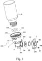
- FIG. 1 to 7 respectively for an exploded view of an essence atomizer having an integrally formed universal connector according to the present invention; a top view of an essence atomizer having an integrally formed universal connector according to the present invention; a cross section view of an essence atomizer having an integrally formed universal connector according to the present invention; a perspective view of an essence atomizer having an integrally formed universal connector according to the first embodiment of the present invention; a cross section view of an essence atomizer having an integrally formed universal connector according to the first embodiment of the present invention; a perspective view of an essence atomizer having an integrally formed universal connector according to a second embodiment of the present invention; and a cross section view of an essence atomizer having an integrally formed universal connector according to a second embodiment of the present invention.
- the present invention provides an essence atomizer having an integrally formed universal connector, comprising: an atomizer universal connector 1 integrally formed into a pipe piece, having a first end portion 11 and a second end portion 12 opposite to the first end portion 11, an inside bend portion 13 is disposed between the first end portion 11 and a second end portion 12, such that an angle is formed between a pipe port 120 of the second end portion 12 and a pipe port 110 of the first end portion 11, the pipe port 110 of the first end portion 11 is greater than the pipe port 120 of the second end portion 12, on the pipe port 110 of the first end portion 11 is disposed inward in sequence a front connection port 111, inner threads 112, and a bottom groove 113 for placing a rubber ring 114, on the pipe port 120 of the second end portion 12 is disposed an expansion ring 121 connected to an atomizer plate 122, an oil prevention pad 123, a nozzle cover 2.
- the nozzle cover 2 is formed into a protrusion plate having a hole. On the four corners of the nozzle cover 2 and around the perimeter of the expansion ring 121 are provided with a plurality of hole locking portions 205, to be fixed and locked by screws 25.
- the present invention has the advantages in that, the entire essence atomizer is more compact in structure and simple in operation. Since the essence atomizer is integrally formed into a piece, so it requires less components, and the production processes can be reduced. As such, it is able to achieve mass production, good quality, water tight seal, and long service life. As shown in Figs. 5 and 7 , in practice, the essence atomizer can be put into outer shells 3 of various shapes, and then connected to an essence container 50 to produce atomizing essence, to avoid the problem of the Prior Art of essence liquid leaking from the atomizer universal connector 1.
- the first end portion 11 is of a cylindrical shape, while the second end portion 12 is of a tapering protrusion shape.
- the minimum distance between the first end portion 11 and the second end portion 12 is 30.4 cm.
- the minimum diameter of the pipe port 110 of the first end portion 11 is ⁇ 28.5, while the minimum diameter of the expansion ring 121 at the second end portion 12 is ⁇ 14.
- the diameter of the atomizer plate 122 is in a range of 13 mm to 14 mm.
- At the second end portion 12 of the atomizer universal connector 1 and on both sides of an expansion ring 121 are provided with at least four hole locking portions 205, for connecting and locking the nozzle cover 2.
- And on both sides of the first end portion 11 of the atomizer universal connector 1 are provided with at least four hole locking portions 205 spaced apart, for locking and connecting in an inner cavity 31 of an outer shell 3.
- the outer shell 3 is a of one of the following shapes: a column, a cube, a sphere, an elliptical sphere, and a polygon.
- the outer shell 3 is used to wrap around and cover the atomizer universal connector 1.
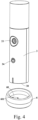
- the outer shell 3 further includes: an electric circuit board 15 connected thereto; a placement port 32 disposed at the first end portion 11 of the atomizer universal connector 1 opposite to the outer shell 3; a sprout 33 disposed at the a nozzle cover 2 opposite to the second end portion 12 ; a control key 34 on the outer shell 3, connected to the electric circuit board 15, the electric circuit board 15 is used to control the atomizer plate 122 to work; a DC power jack 35 disposed on the outer shell 3, for connecting it to a DC power source, to supply power to the electric circuit board 15 (as shown in Fig. 5 ).
- the outer shell 3 can be designed into a cylindrical shape having an upper cover, but the present invention is not limited to this.
- the rear portion of the outer shell 3 further includes: a placement portion 30, and at least two metal contact points 301 are disposed below, to be connected inside the outer shell 3 to a rechargeable battery 400, to supply power to the electrical circuit board 15; and a charging seat 6, on which is disposed a depressed place 60, for removably inserting it into the placement portion 30 of the outer shell 3, on the charging seat 6 is disposed a DC power jack 35 and a conduction plate 601 is embedded in the depressed place 60, to contact and supply power to the two metal contact points 301 in the placement portion 30 of the outer shell 3.
- a rechargeable battery 400 is provided, so that the essence atomizer can be carried to any place to perform essence atomizing.
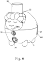
- the outer shell 3 can be made into a shape of a sheep doll, but the present invention is not limited to this. Behind the outer shell 3 is further provided with a depression 36, an USB plug 362 is provided on a bottom portion 361 of the depression 36, a rear cover 37 is disposed at an opening 363 of the depression 36; and an assembled power connector 4, removably inserted in the depression 36, one end of the assembled power connector 4 is provided with a USB socket 436, to be inserted into the USB plug 362, and the other end of the assembled power connector 4 protrudes out a back side of the outer shell 3, and is provided with a power plug 432 for connecting it to a socket (not shown) of a utility power source.
- the essence atomizer can be put on a fixed place, such as on a table.
- a power plug can be put on the back of the essence atomizer, to be inserted into a socket on a wall, to become a wall-insertion-type essence atomizer.
- LEDs can be put into the essence atomizer, to make it a wall-insertion-type essence atomizer having function of night lights.
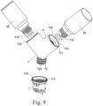
- an expansion universal connector 7 is disposed on the pipe port 110 of the first end portion 11 for the atomizer universal connector 1, the expansion universal connector 7 is formed integrally into a pipe piece, and having a split expansion end 71 and a single pipe connector end 72 connected with each other.
- On the single pipe connector end 72 is disposed outer threads 722 for being locked into the inner threads 112 of the pipe port 110 of the first end portion 11.
- On the split expansion end 71 is provided with at least two pipe ports 710 having an angle formed between them.
- each of the pipe ports 710 is disposed inward in sequence a front connection port 711, inner threads 712, and a bottom groove 713 for receiving a rubber ring 714, to form at least two universal connectors, to be connected and locked onto a corresponding number of an essence containers 50 respectively, thus obtaining a mixture of atomized essences as required.
Landscapes
- Health & Medical Sciences (AREA)
- Epidemiology (AREA)
- Life Sciences & Earth Sciences (AREA)
- Animal Behavior & Ethology (AREA)
- General Health & Medical Sciences (AREA)
- Public Health (AREA)
- Veterinary Medicine (AREA)
- Containers And Packaging Bodies Having A Special Means To Remove Contents (AREA)
- Disinfection, Sterilisation Or Deodorisation Of Air (AREA)
Claims (6)
- Essenzverdampfer (1000):- ein Verdampferanschluss (1), integral zu einem Rohrstück geformt, bestehend aus:- einem ersten Endabschnitt (11) in zylindrischer Form,- einem zweiten Endabschnitt (12) gegenüber dem ersten Endabschnitt in konischer, überstehender Form,- einem inneren gebogenen Abschnitt (13), angeordnet zwischen dem ersten Endabschnitt und einem zweiten Endabschnitt,- einem Rohranschluss (110) des ersten Endabschnitts, bestehend aus (nacheinander nach innen angeordnet):- einem Verbindungsanschluss (111),- Innengewinden (112) und- einer unteren Nut (113) zur Anbringung eines Gummirings (114), wobei der Rohranschluss (110) des ersten Endabschnitts so konfiguriert ist, dass er mit einem Essenzbehälter mit passendem Durchmesser und Schraubgewinde verbunden werden kann,- einem Rohranschluss (120) des zweiten Endabschnitts (12), der einen Winkel mit einem Rohranschluss des ersten Endabschnitts (12) bildet, wobei der Durchmesser des Rohranschlusses (110) des ersten Endabschnitts (11) größer ist als der Durchmesser des Rohranschlusses (120) des zweiten Endabschnitts (12), bestehend aus (nacheinander nach innen angeordnet):- einem Erweiterungsring (121), der mit einer Verdampferplatte (122) verbunden ist, und- einem Ölschutzpolster (123),- einer Düsenabdeckung (2), zu einer überstehenden Platte mit Loch geformt; und- einem Gehäuse (3), um den Verdampferanschluss zu umhüllen und abzudecken, bestehend aus:dadurch gekennzeichnet, dass das Gehäuse ferner über eine am Gehäuse angeordnete Gleichstrombuchse (35) zum Anschluss an eine Gleichstromquelle zur Stromversorgung der elektrischen Leiterplatte verfügt; und dass- einer daran angeschlossenen elektrischen Leiterplatte (15),- einem Schaltanschluss (32) am ersten Endabschnitt des Verdampferanschlusses gegenüber dem Gehäuse,- einem Dorn (33) an der dem zweiten Endabschnitt gegenüberliegenden Düsenabdeckung,- einer Steuertaste (34) am mit der elektrischen Leiterplatte verbundenen Gehäuse, an die die elektrische Leiterplatte angeschlossen ist und worüber die Funktion der Verdampferplatte gesteuert wird;
das Gehäuse (33) ferner Folgendes umfasst:- einen Schaltabschnitt (30), der den Essenzverdampfer in Kontakt mit einer Ladeschale (6) und mindestens zwei Metallkontaktpunkten (301) bringt, die so konfiguriert sind, dass sie einen im Gehäuse eingelegten wiederaufladbaren Akku (400) elektrisch mit der Ladeschale (6) verbinden, um die elektrische Leiterplatte mit Strom zu versorgen; und- eine Ladeschale (6) mit einer Vertiefung (60) zum herausnehmbaren Einsetzen in den Schaltabschnitt (30) des Gehäuses, wobei an der Ladeschale eine Gleichstrombuchse (35) angebracht und eine Leitplatte (601) in die Vertiefung eingebettet ist, um die beiden Metallkontaktpunkte im Schaltabschnitt des Gehäuses in Kontakt zu bringen und mit Strom zu versorgen. - Essenzverdampfer (1000) nach Anspruch 1, wobei das Gehäuse (3) eine der folgenden Formen aufweist: Säule, Würfel, Kugel, elliptische Kugel oder Polygon.
- Essenzverdampfer (1000) nach einem der Ansprüche 1 oder 2, wobei:- der zweite Endabschnitt (12) des Verdampferanschlusses (1) auf beiden Seiten eines Erweiterungsrings (121) mindestens vier Lochverriegelungsabschnitte (205) umfasst,- vier Ecken der Düsenabdeckung (2) jeweils mit einem Lochverriegelungsabschnitt (205) zum Verriegeln bzw. Verbinden durch eine Schraube (25) versehen sind und- beide Seiten des ersten Endabschnitts des Verdampferanschlusses mindestens vier voneinander beabstandete Lochverriegelungsabschnitte (205) zum Verriegeln bzw. Verbinden in einem inneren Hohlraum (31) eines Gehäuses umfassen.
- Essenzverdampfer (1000) nach einem der Ansprüche 1 bis 3, wobei das Gehäuse (3) über eine Rückseite und eine Vorderseite verfügt und wobei die Rückseite Folgendes umfasst:- eine Vertiefung (36) mit einem USB-Stecker (362) an einem unteren Abschnitt (361) der Vertiefung und eine Abdeckung (37) an einer Öffnung (363) der Vertiefung; und- einen zusammengebauten Netzanschluss (4), herausnehmbar in die Vertiefung eingesetzt, wobei sich an einem Ende des zusammengebauten Netzanschlusses eine USB-Buchse (436) befindet, in die der USB-Stecker eingesteckt werden kann, und das andere Ende des zusammengebauten Netzanschlusses aus der Rückseite der Schale herausragt und über einen Netzstecker (432) zum Anschluss an eine herkömmliche Steckdose verfügt.
- Essenzverdampfer (1000) nach einem der Ansprüche 1 bis 4, der ferner Folgendes umfasst:- einen Erweiterungsanschluss (7) am Rohranschluss (110) des ersten Endabschnitts (11) für den Verdampferanschluss, wobei der Erweiterungsanschluss integral zu einem Rohrstück geformt ist, sowie ein geteiltes Erweiterungsende (71) und ein einzelnes Rohranschlussende (72), die miteinander verbunden sind,- das einzelne Rohranschlussende verfügt über Außengewinde (722), über die sich die Innengewinde (112) des Rohranschlusses des ersten Endabschnitts verriegeln lassen,- das geteilte Erweiterungsende ist mit mindestens zwei Rohranschlüssen (710) ausgestattet, zwischen denen sich ein Winkel bildet, wobei jeder Rohranschluss nacheinander Folgendes umfasst:- einen vorderen Verbindungsanschluss (711),- Innengewinde (712) und- eine untere Nut (713) zur Aufnahme eines Gummirings (714), um mindestens zwei Anschlüsse zu bilden, die jeweils mit einem Essenzbehälter (50) verbunden bzw. verriegelt werden sollen.
- Essenzverdampfer (1000) nach einem der Ansprüche 1 bis 5, der ferner mit LEDs ausgestattet ist, die wiederum so konfiguriert sind, dass sie die Umgebung des Essenzverdampfers beleuchten.
Applications Claiming Priority (2)
| Application Number | Priority Date | Filing Date | Title |
|---|---|---|---|
| CN201820958243.XU CN208449737U (zh) | 2018-06-21 | 2018-06-21 | 喷雾通用接头改良结构及其应用 |
| US16/027,189 US10835915B2 (en) | 2018-06-21 | 2018-07-03 | Essence atomizer having integrally formed universal connector |
Publications (3)
| Publication Number | Publication Date |
|---|---|
| EP3586880A1 EP3586880A1 (de) | 2020-01-01 |
| EP3586880C0 EP3586880C0 (de) | 2024-08-14 |
| EP3586880B1 true EP3586880B1 (de) | 2024-08-14 |
Family
ID=69806202
Family Applications (1)
| Application Number | Title | Priority Date | Filing Date |
|---|---|---|---|
| EP19167745.9A Active EP3586880B1 (de) | 2018-06-21 | 2019-04-08 | Essenzzerstäuber |
Country Status (4)
| Country | Link |
|---|---|
| US (1) | US10835915B2 (de) |
| EP (1) | EP3586880B1 (de) |
| JP (1) | JP3222830U (de) |
| CN (1) | CN208449737U (de) |
Families Citing this family (2)
| Publication number | Priority date | Publication date | Assignee | Title |
|---|---|---|---|---|
| CN114405699A (zh) * | 2021-12-01 | 2022-04-29 | 杰瑞华创科技有限公司 | 静电喷雾器 |
| WO2023109084A1 (zh) * | 2021-12-13 | 2023-06-22 | 青岛海尔洗涤电器有限公司 | 雾化装置和衣物处理设备 |
Family Cites Families (7)
| Publication number | Priority date | Publication date | Assignee | Title |
|---|---|---|---|---|
| TWM417925U (en) * | 2011-06-14 | 2011-12-11 | Microbase Technology Corp | Portable atomization device |
| CN204293562U (zh) | 2014-10-16 | 2015-04-29 | 赵宣玉 | 通用式精油扩散仪 |
| US20180326112A1 (en) * | 2015-11-13 | 2018-11-15 | Savvy Inc. | Fragrance dispenser and system, and method for using the same |
| CN208511650U (zh) * | 2016-08-31 | 2019-02-19 | 广东东阳光药业有限公司 | 一种倾斜流道式雾化器 |
| CN107970619A (zh) * | 2017-12-29 | 2018-05-01 | 杭州优晶电子科技有限公司 | 一种用于童车的雾化装置 |
| US10894268B2 (en) * | 2018-02-01 | 2021-01-19 | Foshan Shunde Ultek Electric Appliance Co., Ltd | Ultrasonic essential oil atomizer |
| US20190283067A1 (en) * | 2018-03-15 | 2019-09-19 | Gurunanda, Llc | Gravity fed diffuser |
-
2018
- 2018-06-21 CN CN201820958243.XU patent/CN208449737U/zh not_active Ceased
- 2018-07-03 US US16/027,189 patent/US10835915B2/en active Active
-
2019
- 2019-04-08 EP EP19167745.9A patent/EP3586880B1/de active Active
- 2019-06-17 JP JP2019002171U patent/JP3222830U/ja active Active
Also Published As
| Publication number | Publication date |
|---|---|
| EP3586880C0 (de) | 2024-08-14 |
| CN208449737U (zh) | 2019-02-01 |
| JP3222830U (ja) | 2019-08-29 |
| EP3586880A1 (de) | 2020-01-01 |
| US10835915B2 (en) | 2020-11-17 |
| US20200009599A1 (en) | 2020-01-09 |
Similar Documents
| Publication | Publication Date | Title |
|---|---|---|
| US9623137B2 (en) | Essential oil diffuser | |
| EP3586880B1 (de) | Essenzzerstäuber | |
| CN207653770U (zh) | 一种补水仪 | |
| CN211067352U (zh) | 一种美容仪 | |
| US11000621B2 (en) | Siphon type essence diffuser having block-preventing and leakage-preventing capabilities | |
| JP6289907B2 (ja) | 振動塗布器 | |
| CN206228762U (zh) | 一种多功能美容器 | |
| US12533437B2 (en) | Modular aromatherapy essential oil diffuser | |
| CN213727207U (zh) | 一种花洒 | |
| ES2986715T3 (es) | Atomizador de esencia | |
| CN219251361U (zh) | 一种口腔喷雾器 | |
| CN219614753U (zh) | 便携式美容仪 | |
| CN205613606U (zh) | 精简型通用芳香扩散仪 | |
| CN207887378U (zh) | 一种标识扣盖连接结构以及新型花洒 | |
| CN209075587U (zh) | 具有一体成型通用接头的芳香喷雾结构 | |
| CN212438407U (zh) | 雾化喷嘴及感应式洗手机 | |
| CN218796864U (zh) | 液体雾化装置 | |
| CN222722420U (zh) | 电子雾化器 | |
| CN210432118U (zh) | 过线装置、供电结构和用电器 | |
| CN223335730U (zh) | 化妆品容器 | |
| CN212143126U (zh) | 一种便携式多层密封分体超氧水喷雾器 | |
| CN219783144U (zh) | 一种雾化熏蒸治疗仪 | |
| TWM537428U (zh) | 美妝噴瓶結構 | |
| KR101890532B1 (ko) | 보조 배터리가 내장된 화장품 케이스 | |
| CN221411902U (zh) | 一种雾化仪器的药罐结构 |
Legal Events
| Date | Code | Title | Description |
|---|---|---|---|
| PUAI | Public reference made under article 153(3) epc to a published international application that has entered the european phase |
Free format text: ORIGINAL CODE: 0009012 |
|
| STAA | Information on the status of an ep patent application or granted ep patent |
Free format text: STATUS: THE APPLICATION HAS BEEN PUBLISHED |
|
| AK | Designated contracting states |
Kind code of ref document: A1 Designated state(s): AL AT BE BG CH CY CZ DE DK EE ES FI FR GB GR HR HU IE IS IT LI LT LU LV MC MK MT NL NO PL PT RO RS SE SI SK SM TR |
|
| AX | Request for extension of the european patent |
Extension state: BA ME |
|
| STAA | Information on the status of an ep patent application or granted ep patent |
Free format text: STATUS: REQUEST FOR EXAMINATION WAS MADE |
|
| 17P | Request for examination filed |
Effective date: 20200629 |
|
| RBV | Designated contracting states (corrected) |
Designated state(s): AL AT BE BG CH CY CZ DE DK EE ES FI FR GB GR HR HU IE IS IT LI LT LU LV MC MK MT NL NO PL PT RO RS SE SI SK SM TR |
|
| STAA | Information on the status of an ep patent application or granted ep patent |
Free format text: STATUS: EXAMINATION IS IN PROGRESS |
|
| 17Q | First examination report despatched |
Effective date: 20220104 |
|
| RIC1 | Information provided on ipc code assigned before grant |
Ipc: B05B 17/00 20060101ALN20240418BHEP Ipc: B05B 12/14 20060101ALN20240418BHEP Ipc: A61L 9/14 20060101AFI20240418BHEP |
|
| GRAP | Despatch of communication of intention to grant a patent |
Free format text: ORIGINAL CODE: EPIDOSNIGR1 |
|
| STAA | Information on the status of an ep patent application or granted ep patent |
Free format text: STATUS: GRANT OF PATENT IS INTENDED |
|
| INTG | Intention to grant announced |
Effective date: 20240527 |
|
| RIC1 | Information provided on ipc code assigned before grant |
Ipc: B05B 17/00 20060101ALN20240514BHEP Ipc: B05B 12/14 20060101ALN20240514BHEP Ipc: A61L 9/14 20060101AFI20240514BHEP |
|
| GRAS | Grant fee paid |
Free format text: ORIGINAL CODE: EPIDOSNIGR3 |
|
| GRAA | (expected) grant |
Free format text: ORIGINAL CODE: 0009210 |
|
| STAA | Information on the status of an ep patent application or granted ep patent |
Free format text: STATUS: THE PATENT HAS BEEN GRANTED |
|
| AK | Designated contracting states |
Kind code of ref document: B1 Designated state(s): AL AT BE BG CH CY CZ DE DK EE ES FI FR GB GR HR HU IE IS IT LI LT LU LV MC MK MT NL NO PL PT RO RS SE SI SK SM TR |
|
| REG | Reference to a national code |
Ref country code: GB Ref legal event code: FG4D |
|
| REG | Reference to a national code |
Ref country code: CH Ref legal event code: EP |
|
| REG | Reference to a national code |
Ref country code: DE Ref legal event code: R096 Ref document number: 602019056888 Country of ref document: DE |
|
| REG | Reference to a national code |
Ref country code: IE Ref legal event code: FG4D |
|
| U01 | Request for unitary effect filed |
Effective date: 20240913 |
|
| U07 | Unitary effect registered |
Designated state(s): AT BE BG DE DK EE FI FR IT LT LU LV MT NL PT RO SE SI Effective date: 20241002 |
|
| REG | Reference to a national code |
Ref country code: ES Ref legal event code: FG2A Ref document number: 2986715 Country of ref document: ES Kind code of ref document: T3 Effective date: 20241112 |
|
| PG25 | Lapsed in a contracting state [announced via postgrant information from national office to epo] |
Ref country code: NO Free format text: LAPSE BECAUSE OF FAILURE TO SUBMIT A TRANSLATION OF THE DESCRIPTION OR TO PAY THE FEE WITHIN THE PRESCRIBED TIME-LIMIT Effective date: 20241114 |
|
| PG25 | Lapsed in a contracting state [announced via postgrant information from national office to epo] |
Ref country code: PL Free format text: LAPSE BECAUSE OF FAILURE TO SUBMIT A TRANSLATION OF THE DESCRIPTION OR TO PAY THE FEE WITHIN THE PRESCRIBED TIME-LIMIT Effective date: 20240814 Ref country code: GR Free format text: LAPSE BECAUSE OF FAILURE TO SUBMIT A TRANSLATION OF THE DESCRIPTION OR TO PAY THE FEE WITHIN THE PRESCRIBED TIME-LIMIT Effective date: 20241115 |
|
| PG25 | Lapsed in a contracting state [announced via postgrant information from national office to epo] |
Ref country code: IS Free format text: LAPSE BECAUSE OF FAILURE TO SUBMIT A TRANSLATION OF THE DESCRIPTION OR TO PAY THE FEE WITHIN THE PRESCRIBED TIME-LIMIT Effective date: 20241214 |
|
| PG25 | Lapsed in a contracting state [announced via postgrant information from national office to epo] |
Ref country code: HR Free format text: LAPSE BECAUSE OF FAILURE TO SUBMIT A TRANSLATION OF THE DESCRIPTION OR TO PAY THE FEE WITHIN THE PRESCRIBED TIME-LIMIT Effective date: 20240814 |
|
| PG25 | Lapsed in a contracting state [announced via postgrant information from national office to epo] |
Ref country code: RS Free format text: LAPSE BECAUSE OF FAILURE TO SUBMIT A TRANSLATION OF THE DESCRIPTION OR TO PAY THE FEE WITHIN THE PRESCRIBED TIME-LIMIT Effective date: 20241114 |
|
| PG25 | Lapsed in a contracting state [announced via postgrant information from national office to epo] |
Ref country code: RS Free format text: LAPSE BECAUSE OF FAILURE TO SUBMIT A TRANSLATION OF THE DESCRIPTION OR TO PAY THE FEE WITHIN THE PRESCRIBED TIME-LIMIT Effective date: 20241114 Ref country code: PL Free format text: LAPSE BECAUSE OF FAILURE TO SUBMIT A TRANSLATION OF THE DESCRIPTION OR TO PAY THE FEE WITHIN THE PRESCRIBED TIME-LIMIT Effective date: 20240814 Ref country code: NO Free format text: LAPSE BECAUSE OF FAILURE TO SUBMIT A TRANSLATION OF THE DESCRIPTION OR TO PAY THE FEE WITHIN THE PRESCRIBED TIME-LIMIT Effective date: 20241114 Ref country code: IS Free format text: LAPSE BECAUSE OF FAILURE TO SUBMIT A TRANSLATION OF THE DESCRIPTION OR TO PAY THE FEE WITHIN THE PRESCRIBED TIME-LIMIT Effective date: 20241214 Ref country code: HR Free format text: LAPSE BECAUSE OF FAILURE TO SUBMIT A TRANSLATION OF THE DESCRIPTION OR TO PAY THE FEE WITHIN THE PRESCRIBED TIME-LIMIT Effective date: 20240814 Ref country code: GR Free format text: LAPSE BECAUSE OF FAILURE TO SUBMIT A TRANSLATION OF THE DESCRIPTION OR TO PAY THE FEE WITHIN THE PRESCRIBED TIME-LIMIT Effective date: 20241115 |
|
| PG25 | Lapsed in a contracting state [announced via postgrant information from national office to epo] |
Ref country code: SM Free format text: LAPSE BECAUSE OF FAILURE TO SUBMIT A TRANSLATION OF THE DESCRIPTION OR TO PAY THE FEE WITHIN THE PRESCRIBED TIME-LIMIT Effective date: 20240814 |
|
| PG25 | Lapsed in a contracting state [announced via postgrant information from national office to epo] |
Ref country code: CZ Free format text: LAPSE BECAUSE OF FAILURE TO SUBMIT A TRANSLATION OF THE DESCRIPTION OR TO PAY THE FEE WITHIN THE PRESCRIBED TIME-LIMIT Effective date: 20240814 |
|
| PG25 | Lapsed in a contracting state [announced via postgrant information from national office to epo] |
Ref country code: SK Free format text: LAPSE BECAUSE OF FAILURE TO SUBMIT A TRANSLATION OF THE DESCRIPTION OR TO PAY THE FEE WITHIN THE PRESCRIBED TIME-LIMIT Effective date: 20240814 |
|
| U20 | Renewal fee for the european patent with unitary effect paid |
Year of fee payment: 7 Effective date: 20250429 |
|
| PLBE | No opposition filed within time limit |
Free format text: ORIGINAL CODE: 0009261 |
|
| STAA | Information on the status of an ep patent application or granted ep patent |
Free format text: STATUS: NO OPPOSITION FILED WITHIN TIME LIMIT |
|
| PGFP | Annual fee paid to national office [announced via postgrant information from national office to epo] |
Ref country code: GB Payment date: 20250429 Year of fee payment: 7 Ref country code: ES Payment date: 20250626 Year of fee payment: 7 |
|
| 26N | No opposition filed |
Effective date: 20250515 |
|
| PGFP | Annual fee paid to national office [announced via postgrant information from national office to epo] |
Ref country code: CH Payment date: 20250602 Year of fee payment: 7 |
|
| PG25 | Lapsed in a contracting state [announced via postgrant information from national office to epo] |
Ref country code: MC Free format text: LAPSE BECAUSE OF FAILURE TO SUBMIT A TRANSLATION OF THE DESCRIPTION OR TO PAY THE FEE WITHIN THE PRESCRIBED TIME-LIMIT Effective date: 20240814 |
|
| PG25 | Lapsed in a contracting state [announced via postgrant information from national office to epo] |
Ref country code: IE Free format text: LAPSE BECAUSE OF NON-PAYMENT OF DUE FEES Effective date: 20250408 |