EP3586807B1 - Medical device - Google Patents
Medical device Download PDFInfo
- Publication number
- EP3586807B1 EP3586807B1 EP17897961.3A EP17897961A EP3586807B1 EP 3586807 B1 EP3586807 B1 EP 3586807B1 EP 17897961 A EP17897961 A EP 17897961A EP 3586807 B1 EP3586807 B1 EP 3586807B1
- Authority
- EP
- European Patent Office
- Prior art keywords
- main body
- base
- load
- extension
- floor surface
- Prior art date
- Legal status (The legal status is an assumption and is not a legal conclusion. Google has not performed a legal analysis and makes no representation as to the accuracy of the status listed.)
- Active
Links
Images




Classifications
-
- A—HUMAN NECESSITIES
- A61—MEDICAL OR VETERINARY SCIENCE; HYGIENE
- A61G—TRANSPORT, PERSONAL CONVEYANCES, OR ACCOMMODATION SPECIALLY ADAPTED FOR PATIENTS OR DISABLED PERSONS; OPERATING TABLES OR CHAIRS; CHAIRS FOR DENTISTRY; FUNERAL DEVICES
- A61G13/00—Operating tables; Auxiliary appliances therefor
- A61G13/02—Adjustable operating tables; Controls therefor
-
- A—HUMAN NECESSITIES
- A61—MEDICAL OR VETERINARY SCIENCE; HYGIENE
- A61G—TRANSPORT, PERSONAL CONVEYANCES, OR ACCOMMODATION SPECIALLY ADAPTED FOR PATIENTS OR DISABLED PERSONS; OPERATING TABLES OR CHAIRS; CHAIRS FOR DENTISTRY; FUNERAL DEVICES
- A61G13/00—Operating tables; Auxiliary appliances therefor
- A61G13/10—Parts, details or accessories
-
- A—HUMAN NECESSITIES
- A61—MEDICAL OR VETERINARY SCIENCE; HYGIENE
- A61G—TRANSPORT, PERSONAL CONVEYANCES, OR ACCOMMODATION SPECIALLY ADAPTED FOR PATIENTS OR DISABLED PERSONS; OPERATING TABLES OR CHAIRS; CHAIRS FOR DENTISTRY; FUNERAL DEVICES
- A61G13/00—Operating tables; Auxiliary appliances therefor
- A61G13/02—Adjustable operating tables; Controls therefor
- A61G13/08—Adjustable operating tables; Controls therefor the table being divided into different adjustable sections
-
- A—HUMAN NECESSITIES
- A61—MEDICAL OR VETERINARY SCIENCE; HYGIENE
- A61G—TRANSPORT, PERSONAL CONVEYANCES, OR ACCOMMODATION SPECIALLY ADAPTED FOR PATIENTS OR DISABLED PERSONS; OPERATING TABLES OR CHAIRS; CHAIRS FOR DENTISTRY; FUNERAL DEVICES
- A61G13/00—Operating tables; Auxiliary appliances therefor
- A61G13/10—Parts, details or accessories
- A61G13/104—Adaptations for table mobility, e.g. arrangement of wheels
-
- G—PHYSICS
- G01—MEASURING; TESTING
- G01G—WEIGHING
- G01G19/00—Weighing apparatus or methods adapted for special purposes not provided for in the preceding groups
- G01G19/52—Weighing apparatus combined with other objects, e.g. furniture
-
- A—HUMAN NECESSITIES
- A47—FURNITURE; DOMESTIC ARTICLES OR APPLIANCES; COFFEE MILLS; SPICE MILLS; SUCTION CLEANERS IN GENERAL
- A47B—TABLES; DESKS; OFFICE FURNITURE; CABINETS; DRAWERS; GENERAL DETAILS OF FURNITURE
- A47B2220/00—General furniture construction, e.g. fittings
- A47B2220/0027—Feet
- A47B2220/003—Height-adjustable feet or gliders for tables or desks
-
- A—HUMAN NECESSITIES
- A47—FURNITURE; DOMESTIC ARTICLES OR APPLIANCES; COFFEE MILLS; SPICE MILLS; SUCTION CLEANERS IN GENERAL
- A47B—TABLES; DESKS; OFFICE FURNITURE; CABINETS; DRAWERS; GENERAL DETAILS OF FURNITURE
- A47B91/00—Feet for furniture in general
- A47B91/02—Adjustable feet
-
- A—HUMAN NECESSITIES
- A61—MEDICAL OR VETERINARY SCIENCE; HYGIENE
- A61G—TRANSPORT, PERSONAL CONVEYANCES, OR ACCOMMODATION SPECIALLY ADAPTED FOR PATIENTS OR DISABLED PERSONS; OPERATING TABLES OR CHAIRS; CHAIRS FOR DENTISTRY; FUNERAL DEVICES
- A61G2203/00—General characteristics of devices
- A61G2203/10—General characteristics of devices characterised by specific control means, e.g. for adjustment or steering
- A61G2203/16—Touchpads
-
- A—HUMAN NECESSITIES
- A61—MEDICAL OR VETERINARY SCIENCE; HYGIENE
- A61G—TRANSPORT, PERSONAL CONVEYANCES, OR ACCOMMODATION SPECIALLY ADAPTED FOR PATIENTS OR DISABLED PERSONS; OPERATING TABLES OR CHAIRS; CHAIRS FOR DENTISTRY; FUNERAL DEVICES
- A61G2203/00—General characteristics of devices
- A61G2203/30—General characteristics of devices characterised by sensor means
- A61G2203/44—General characteristics of devices characterised by sensor means for weight
-
- B—PERFORMING OPERATIONS; TRANSPORTING
- B60—VEHICLES IN GENERAL
- B60B—VEHICLE WHEELS; CASTORS; AXLES FOR WHEELS OR CASTORS; INCREASING WHEEL ADHESION
- B60B2200/00—Type of product being used or applied
- B60B2200/20—Furniture or medical appliances
- B60B2200/22—Chairs
-
- B—PERFORMING OPERATIONS; TRANSPORTING
- B60—VEHICLES IN GENERAL
- B60B—VEHICLE WHEELS; CASTORS; AXLES FOR WHEELS OR CASTORS; INCREASING WHEEL ADHESION
- B60B2200/00—Type of product being used or applied
- B60B2200/20—Furniture or medical appliances
- B60B2200/24—Beds
- B60B2200/242—Hospital beds
-
- B—PERFORMING OPERATIONS; TRANSPORTING
- B60—VEHICLES IN GENERAL
- B60B—VEHICLE WHEELS; CASTORS; AXLES FOR WHEELS OR CASTORS; INCREASING WHEEL ADHESION
- B60B33/00—Castors in general ; Anti-clogging castors
- B60B33/0078—Castors in general ; Anti-clogging castors characterised by details of the wheel braking mechanism
- B60B33/0089—Castors in general ; Anti-clogging castors characterised by details of the wheel braking mechanism acting on the floor
-
- B—PERFORMING OPERATIONS; TRANSPORTING
- B60—VEHICLES IN GENERAL
- B60B—VEHICLE WHEELS; CASTORS; AXLES FOR WHEELS OR CASTORS; INCREASING WHEEL ADHESION
- B60B33/00—Castors in general ; Anti-clogging castors
- B60B33/04—Castors in general ; Anti-clogging castors adjustable, e.g. in height; linearly shifting castors
- B60B33/06—Castors in general ; Anti-clogging castors adjustable, e.g. in height; linearly shifting castors mounted retractably
Definitions
- the present invention relates to medical device, and particularly relates to an overturning prevention mechanism of a surgical operation table.
- a surgical operation table is required to be provided with a function of being able to freely change a height and an inclination of a table on which a patient is laid, because the surgical operation table needs to move a specific part of the patient to a position where a doctor can easily treat the specific part of the patient, and there has been a conventionally known surgical operation table provided with an elevating function and an inclining function for a table (refer to Patent Literature 1).
- JP S50 5665 U discloses a medical bed
- US 5 747 745 A discloses a weighting device for bedridden patients
- DE 91 13 089 U1 discloses a hospital bed.
- Casters are generally attached to the surgical operation table like this, and the surgical operation table is easily moved to a predetermined position in a room. Further, it is dangerous for the surgical operation table to move freely, so that a locking device such as a stopper is usually provided so that the casters do not rotate.
- Patent Literature 1 Japanese Patent Laid-Open No. 2004-73616
- the surgical operation table of this kind has a risk of overturning due to movement of the center of gravity by changing the height and inclination of the table, although the height and inclination of the table can be freely changed.
- overturning of the surgical operation table can be prevented by properly detecting the movement of the center of gravity, but there is a request to realize prevention of overturning without performing significant design changes in order to prevent manufacture cost from soaring.
- the present application has an object to provide medical device capable of properly measuring a center of gravity and a load that is applied to a surgical operation table, and capable of preventing overturning of the surgical operation table, failure due to overweight and the like, without performing a significant design change.
- medical device (S) is medical device including a plurality of leg portions (20) that lift up a main body (2) from a floor surface and support the main body, and includes a load detection means (56) that is provided between the main body and each of the leg portions, and detects a load in a vertical direction that is received by the leg portion from the floor surface.
- the leg portion includes a caster (22) capable of moving the main body.
- the leg portion includes a caster capable of moving the main body, and an extension and contraction unit (32) that brings the caster into contact with the floor surface, or lifts up the caster and the main body from the floor surface, by extending or contracting a rod (34), and the load detection means is provided between the main body, and the extension and contraction unit.
- a guide (64) that is capable of moving the extension and contraction unit in the vertical direction is provided, and in a state where the caster is in contact with the floor surface and the rod is not in contact with the floor, the extension and contraction unit is held by the guide in a state where contact of the load detection means and the extension and contraction unit is broken.
- the medical device according to claim 2 is the medical device according to claim 1, and further includes a determination means that determines a risk of overturning of the main body based on loads measured by a plurality of the load detection means.
- the load which is applied to the medical device such as a surgical operation table and the center of gravity at the time of the load being applied can be accurately measured, and the risk of overturning and the risk of failure due to overweight and the like can be communicated to the user based on the measurement result, with the simple mechanism.
- a surgical operation table S of the present embodiment is a concept also including a medical examination table, a treatment table and the like for different use purposes, but is not limited to this field, and it is also possible to use the surgical operation table S in ordinary medical device having a risk of overturning.
- the surgical operation table S of the present embodiment includes a base 2 (a main body in the present application) that is placed on a floor of a surgical operation room, a column 5 that is raised from the base 2, and a table 10 that is provided on the column 5, for example.
- the column 5 includes an extension and contraction mechanism capable of moving the table 10 in a vertical direction with respect to the base 2, and a user can adjust a height of the table 10 to a desired height by the extension and contraction mechanism.
- the table 10 includes a base portion (not illustrated) that is mounted on the column 5, a movable portion (not illustrated) that moves in a horizontal direction, or tilts in a longitudinal/lateral direction with respect to the base portion, and a table main body 15 that is placed on the movable portion.
- the table main body 15 is movable in an up-down direction with an extension and contraction operation of the column 5, and is capable of tilting in the longitudinal/lateral direction, or moving in a horizontal plane with movement of the movable portion.
- Mechanisms that cause the table main body 15 to perform these movements are provided in the movable portion and the column 5, but the mechanisms are techniques known to the public, so that explanation and illustration of the mechanisms are omitted.
- the base 2 includes a base main body 3, and a leg section 20 that lifts up the base main body 3 from a floor surface and support the base main body 3.
- a caster 22 capable of rolling on the floor surface is used as illustrated in FIG. 1 and FIG. 2 , for example, and the casters 22 are provided at four corners in a front and a rear of an undersurface of the base main body 3. It is possible to move the surgical operation table S freely on the floor surface by the casters 22.
- the base main body 3 has a casing 3a, a control device or the like for electrically controlling movement of the surgical operation table S is housed inside the casing 3a, and a touch panel type display body 7 for operating the surgical operation table S is provided on a surface of a rear upper portion. Further, the surgical operation table S is separately provided with a remote controller that is electrically connected to the control device, and on which buttons for electrically controlling the surgical operation table S are disposed. The user is capable of operating the surgical operation table S by using the remote controller or the display body 7.
- the base 2 is provided with a locking device 30 that lifts up the base 2 and separates the casters 22 from the floor surface so that the surgical operation table S does not move, and locks the surgical operation table S into a predetermined position.
- the locking device 30 includes a hydraulic unit 32 (an extension and contraction unit of the present application), and a hydraulic pressure generating device 38 that is connected to the hydraulic unit 32 via a flow path 37. Note that the locking device 30 also functions as the leg section 20 that lifts up the base 2 from the floor surface and supports the surgical operation table S instead of the caster 22.
- the hydraulic unit 32 is a cylinder device of a single-acting type and a hydraulic type, for example, and includes a cylindrical cylinder main body 33 with one end closed, and a rod 34 that extends and contracts in one direction by hydraulic pressure from an open end of the cylinder main body 33, as illustrated in FIG. 4 .
- the hydraulic unit 32 is capable of extending and contracting the rod 34 by the working oil being supplied to the cylinder main body 33 via the flow path 37 from the hydraulic pressure generating device 38, or the working oil being discharged from the cylinder main body 33 via the flow path 37, and in a locking operation of the base 2 by the locking device 30, the hydraulic unit 32 causes the rod 34 to perform an extension operation as illustrated in FIG. 5(b) , and in an unlocking operation of the base 2 by the locking device 30, the hydraulic unit 32 causes the rod 34 to perform a contraction operation as illustrated in FIG. 5(a) .
- a locking operation of the base 2 by the locking device 30 is an operation of supporting the base 2 by the rod 34, and is an operation of separating the caster 22 from the floor surface with the base main body 3, and "an unlocking operation of the base 2 by the locking device 30” is an operation of separating the rod 34 from the floor surface by contracting the rod 34, and supporting the base main body 3 by the caster 22.
- the locking devices 30 are attached to an undersurface of the base main body 3 at a plurality of locations with a predetermined distribution, and specifically are disposed at four locations of the corner portions in close vicinity of the respective casters 22 included in the front side and the rear side of the base main body 3, and the rods 34 are disposed in such a manner that tip end portions thereof face the floor surface.
- the rod 34 is caused to perform an extension operation in the vertical direction to press the floor surface with the rod 34, whereby the caster 22 is lifted up from the floor surface, and the base 2 is supported by the rod 34.
- the rod 34 is caused to perform a contraction operation in the vertical direction to separate the rod 34 from the floor surface, whereby the caster 22 is brought into contact with the floor surface and the base 2 is supported by the caster 22.
- the surgical operation table S of the present embodiment includes a risk determination device 50 that measures a load that is applied to the table 10, and determines a risk of overturning of the surgical operation table S due to movement of the center of gravity, a risk of a failure of the surgical operation table S by the load exceeding the load capacity being applied to the table 10 and the like.
- the risk determination device 50 includes a plurality of load measuring instruments 55 that measure a load in the vertical direction that is received from the floor surface in the locking operation of the base 2 by the locking device 30, and a determination device (determination means of the present application) that determines a risk of failure and breakage due to over load, and a risk of overturning based on measurement results measured by the respective load measuring instruments 55.
- the determination device is included in the aforementioned control device, and the control device includes a CPU (Central Processing Unit), a RAM (Random Access Memory), a ROM (Read Only Memory) and the like though not illustrated, and controls an operation of the entire surgical operation table, and functions as the determination means of the present application, by the CPU executing various programs stored in the ROM, for example.
- the control device measures the loads that are applied to the respective leg portions 20, based on output signals outputted from the respective load measuring instruments 55, and determines a risk of failure and breakage by over load from the measurement values.
- control device measures the loads that are applied to the respective leg portions 20, and determines that there is a possibility of failure and breakage when the measurement values are larger than a specified value specified in advance, and performs sound output processing and display processing to make warning by warning sound and display.
- control device determines a risk of overturning by movement of the center of gravity, measures the loads that are applied to the respective leg portions 20 based on the output signals outputted from the respective load measuring instruments 55, and determines the risk of overturning from the measurement values.
- the control device obtains the loads that are applied to the respective leg portions 20 on the front and rear, determines that there is the risk of overturning to the other side when a load on either one of the front and rear is smaller than a predetermined threshold A that is set in advance, and performs sound output processing and display processing to make warning by warning sound and display, for example.
- a compression type load cell 56 is used, as illustrated in FIG. 4(b) and FIG. 5 .
- the load cell 56 has an outer shape formed into a circular column shape, and has a circular working region 56a where a load is detected, in a substantially center portion of a surface on one side, for example.
- the load cell 56 is disposed between the base 2 and the locking device 30, and a load that is applied in the vertical direction to the working region 56a at a time of extension operation of the rod 34 is measured.
- the load cell 56 is held with the working region 56a facing downward by a base seat 62 where a recessed portion 61 that holds the road cell 56 is formed in a central portion. Further, the hydraulic unit 32 is held to be slidable in the vertical direction by a holder 64.
- the holder 64 has a space portion that houses the hydraulic unit 32 inside, includes engaging bodies 65 that engage with a lower end edge portion of the cylinder main body 33 of the hydraulic unit 32, at a lower end, and prevents falling of the cylinder main body 33.
- the holder 64 has a shape designed to have a predetermined gap t between the cylinder main body 33 and the load cell 56 as illustrated in FIG. 5(a) in the unlocking operation of the base 2 by the locking device 30, and is fixed to the base seat 62.
- An upper end surface of the cylinder main body 33 is formed into a flat shape, in the locking operation of the base 2 by the locking device 30, the cylinder main body 33 moves upward by the extension operation of the rod 34 and an upper end surface thereof is brought into contact with the working region 56a of the load cell 56 as illustrated in FIG. 5(b) .
- the hydraulic unit 32 is disposed under the load cell 56 by having the predetermined gap t and is disposed movably up and down with the center axis of the cylinder main body 33 and a center axis of the working region 56a of the load cell 56 corresponding to each other in the contraction operation of the rod 34, by the holder 64.
- the surgical operation table S configured in this way measures the load received by the rod 34 from the floor surface by the load cell 56, through the upper end surface of the cylinder main body 33 being brought into contact with the working region 56a of the load cell 56 as illustrated in FIG. 5(b) .
- the cylinder main body 33 moves upward in the vertical direction along an inner surface of the holder 64 by the holder 64, and the base 2 is lifted up in a state where the center axis of the working region 56a of the load cell 56 and the center axis of the cylinder main body 33 correspond to each other, so that forces in other directions than the vertical direction do not act on the working region 56a, and the load received from the floor surface is properly transmitted to the working region 56a. Accordingly, the load that acts on the base 2 can be accurately measured.
- the cylinder main body 33 moves downward vertically along the inner surface of the holder 64, and has the gap t between the cylinder main body 33 and the load cell 56. Accordingly, an external force does not act on the working region 56a of the load cell 56, and it prevents occurrence of an erroneous operation by the cylinder main body 33 always contacting the working region 56a, a failure and the like due to vibration and the like at a time of moving the surgical operation table.
- the base seat 62 may be formed on the base 2, and is not an essential element. Further, a shape of the recessed portion 61 may be in any form as long as the recessed portion 61 can hold the load cell 56 so that the load cell 56 can not move.
- the holder 64 can hold the hydraulic unit 32 movably in the vertical direction by having a gap from the load cell 56 in the state where the rod 34 is contracted, and does not have to be in a shape that completely surrounds a periphery of the cylinder main body 33.
- members in circular arc shapes in plan view that are divided into two may be disposed to face each other, for example.
- the surgical operation table S is movable by the casters 22, and is movable to a predetermined position in a surgical operation room, for example. Further, at a time of a surgical operation, in order to prevent unintended movement of the surgical operation table S, a locking operation of the base 2 by the locking device 30 is performed. Further, for the table main body 15, elevation, movement within the horizontal plane, or crosswise turn/lengthwise turn operation is performed so that a doctor easily performs treatment.
- the load in the vertical direction which is received by the leg portion 20 from the floor surface is transmitted to the working region 56a of the load cell 56 by the extension operation of the rod 34, and the output signal indicating the load is outputted to the control device.
- the control device obtains the loads that are applied to the respective leg portions 20 on the front and rear, based on the output signals outputted from the load cells 56 that are disposed in the respective leg portions 20, and when the load on either one of the front and rear is smaller than the predetermined threshold A which is set in advance, the control device determines that there is the risk of overturning to the other side, and performs sound output processing and display processing to make warning by warning sound and display.
- overturning to the front and rear is mentioned, but presence or absence of a risk of overturning as the entire surgical operation table S may be determined with overturning to the left and right also taken into consideration.
- a load distribution applied to the entire base 2 is obtained from the loads which are applied to the respective leg portions 20, and presence or absence of a risk of overturning may be determined.
- the present operation example differs from the above described operation example in terms of preventing a failure and breakage by over load.
- the surgical operation table S is movable by the casters 22, and is movable to the predetermined position in the surgical operation room, for example.
- a locking operation of the base 2 by the locking device 30 is performed.
- elevation, movement within the horizontal plane, or crosswise turn/lengthwise turn operation is performed so that a doctor easily performs treatment.
- the load in the vertical direction received by the leg portion 20 from the floor surface is transmitted to the working region 56a of the load cell 56 by the extension operation of the rod 34, and an output signal indicating the load is outputted to the control device.
- the control device obtains the loads which are applied to the respective leg portions 20 on the front and rear based on the output signals which are outputted from the load cells 56 which are disposed in the respective leg portions 20, obtains the entire load which is applied to all the leg portions 20, determines that there is a risk of a failure and breakage due to over load when the entire load and the loads that are applied to the respective leg portions 20 are larger than a predetermined threshold B which is set in advance, and performs sound output processing and display processing to make warning by warning sound and display.
- a load distribution which is applied to the entire base 2 is obtained from the loads which are applied to the respective leg portions 20, it is determined whether or not there is a location having a risk of a failure and breakage due to over load, and the location having the risk may be determined.
- the surgical operation table S of the present embodiment is the surgical operation table S including the plurality of leg portions 20 that lift up the base 2 on which the table 10 and the column 5 are placed from the floor surface and support the base 2, includes the load cell 56 that is provided between the base 2 and each of the leg portions 20, and detects the load in the vertical direction received by the leg portion 20 from the floor surface.
- the leg portion 20 includes the caster 22 capable of moving the base 2, and the hydraulic unit 32 that brings the caster 22 into contact with the floor surface, or lifts up the caster 22 and the base 2 from the floor surface by extending or contracting the rod 34.
- the load cell 56 is provided between the base 2 and the hydraulic unit 32, and has the gap t between the working region 56a of the load cell 56 and the hydraulic unit 32 at the time of contraction operation of the rod 34 of the hydraulic unit 32.
- the base 2 can be locked so that the surgical operation table S cannot move, the loads that act on the respective leg portions 20 supporting the base 2 are accurately measured, and from the measurement result, a risk of overturning and a risk of a failure or the like by overweight can be determined.
- the present embodiment is only one mode, and the present invention is not limited to this mode.
- measurement of the load by the load cell 56 is performed at the time of locking operation of the base 2 by the locking device 30 which is provided separately from the caster 22, but it is further disclosed, but not part of the invention, that measurement of the load by the load cell 56 may be always performed.
- the load cell 56 can be provided between the caster 22 and the base 2, for example, and preferably, as illustrated in FIG.
- a holder 72 that slidably holds a shaft 71 in the vertical direction is attached to the base 2 so that forces in other directions than the vertical direction cannot act on the working region 56a of the load cell 56, the caster 22 is provided at a lower end of the shaft 71, and the load cell 56 may be provided between the shaft 71 and the base 2.
- a single-acting type cylinder is used as the hydraulic unit, but it may be the leg portion 20 that is extensible and contractible so as to support the base 2 as a substitute for the caster 22, may be a mechanical type of extension and contraction device such as a pinion rack, and is not limited to a mechanical type or an electric type, and other generally known extension and contraction devices may be adopted.
- the load measuring instrument the compression type load cell is used, but the load measuring instrument is not limited to this mode, but may be in any mode as long as the instrument can measure a load by contact.
Landscapes
- Health & Medical Sciences (AREA)
- Engineering & Computer Science (AREA)
- Biomedical Technology (AREA)
- Life Sciences & Earth Sciences (AREA)
- Animal Behavior & Ethology (AREA)
- General Health & Medical Sciences (AREA)
- Public Health (AREA)
- Veterinary Medicine (AREA)
- Mechanical Engineering (AREA)
- Physics & Mathematics (AREA)
- General Physics & Mathematics (AREA)
- Accommodation For Nursing Or Treatment Tables (AREA)
Description
- The present invention relates to medical device, and particularly relates to an overturning prevention mechanism of a surgical operation table.
- A surgical operation table is required to be provided with a function of being able to freely change a height and an inclination of a table on which a patient is laid, because the surgical operation table needs to move a specific part of the patient to a position where a doctor can easily treat the specific part of the patient, and there has been a conventionally known surgical operation table provided with an elevating function and an inclining function for a table (refer to Patent Literature 1).
JP S50 5665 U US 5 747 745 A discloses a weighting device for bedridden patients,DE 91 13 089 U1 discloses a hospital bed. - Casters are generally attached to the surgical operation table like this, and the surgical operation table is easily moved to a predetermined position in a room. Further, it is dangerous for the surgical operation table to move freely, so that a locking device such as a stopper is usually provided so that the casters do not rotate.
- Further, there is known a method of lifting up a surgical operation table by providing rods capable of extension and contraction close to the respective casters, as the locking device, and by causing the plurality of rods to perform extension movement.
- Patent Literature 1:
Japanese Patent Laid-Open No. 2004-73616 - Incidentally, the surgical operation table of this kind has a risk of overturning due to movement of the center of gravity by changing the height and inclination of the table, although the height and inclination of the table can be freely changed.
- Accordingly, overturning of the surgical operation table can be prevented by properly detecting the movement of the center of gravity, but there is a request to realize prevention of overturning without performing significant design changes in order to prevent manufacture cost from soaring.
- Further, when a load exceeding a load capacity of the table is applied, the load becomes the cause of breakage and failure of the surgical operation table, so that it is necessary to measure the load which is applied to the surgical operation table accurately.
- Thus, in order to solve an example of the problem like this, the present application has an object to provide medical device capable of properly measuring a center of gravity and a load that is applied to a surgical operation table, and capable of preventing overturning of the surgical operation table, failure due to overweight and the like, without performing a significant design change.
- In order to solve the above described problem, medical device (S) according to claim 1 is medical device including a plurality of leg portions (20) that lift up a main body (2) from a floor surface and support the main body, and includes a load detection means (56) that is provided between the main body and each of the leg portions, and detects a load in a vertical direction that is received by the leg portion from the floor surface.
- Further, in the medical device according to claim 1, the leg portion includes a caster (22) capable of moving the main body.
- Further, in the medical device according to claim 1, the leg portion includes a caster capable of moving the main body, and an extension and contraction unit (32) that brings the caster into contact with the floor surface, or lifts up the caster and the main body from the floor surface, by extending or contracting a rod (34), and the load detection means is provided between the main body, and the extension and contraction unit.
- Further, in the medical device according to claim 1, a guide (64) that is capable of moving the extension and contraction unit in the vertical direction is provided, and in a state where the caster is in contact with the floor surface and the rod is not in contact with the floor, the extension and contraction unit is held by the guide in a state where contact of the load detection means and the extension and contraction unit is broken.
- Further, the medical device according to
claim 2 is the medical device according to claim 1, and further includes a determination means that determines a risk of overturning of the main body based on loads measured by a plurality of the load detection means. - The load which is applied to the medical device such as a surgical operation table and the center of gravity at the time of the load being applied can be accurately measured, and the risk of overturning and the risk of failure due to overweight and the like can be communicated to the user based on the measurement result, with the simple mechanism.
-
- [
FIG. 1] FIG. 1 is a perspective view illustrating an example of an external appearance of a surgical operation table. - [
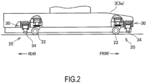
FIG. 2] FIG. 2 is a configuration view of a base illustrating an unlocking operation example of the base by a locking device. - [
FIG. 3] FIG. 3 is a configuration view of the base illustrating a locking operation example of the base by the locking device. - [
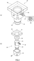
FIG. 4] FIG. 4 shows an attaching example of a load cell, -
FIG. 4(a) is an assembled state view, andFIG. 4(b) is an exploded perspective view. - [
FIG. 5] FIG. 5 is a view for explaining an operation example of a load cell in the locking or unlocking operation of the base by the locking device. - [
FIG. 6] FIG. 6 is a simple system diagram of an overturning prevention device. - [
FIG. 7] FIG. 7 is a schematic view illustrating another attaching example of the load cell. - Hereinafter, a mode for carrying out the present invention will be described based on an embodiment of the present invention illustrated in the accompanying drawings. Note that in the following explanation, working oil refers to a fluid that is used as a power transmission medium in a hydraulic cylinder device. Further, a surgical operation table S of the present embodiment is a concept also including a medical examination table, a treatment table and the like for different use purposes, but is not limited to this field, and it is also possible to use the surgical operation table S in ordinary medical device having a risk of overturning.
- As illustrated in
FIG. 1 , the surgical operation table S of the present embodiment includes a base 2 (a main body in the present application) that is placed on a floor of a surgical operation room, acolumn 5 that is raised from thebase 2, and a table 10 that is provided on thecolumn 5, for example. - The
column 5 includes an extension and contraction mechanism capable of moving the table 10 in a vertical direction with respect to thebase 2, and a user can adjust a height of the table 10 to a desired height by the extension and contraction mechanism. - The table 10 includes a base portion (not illustrated) that is mounted on the
column 5, a movable portion (not illustrated) that moves in a horizontal direction, or tilts in a longitudinal/lateral direction with respect to the base portion, and a tablemain body 15 that is placed on the movable portion. - The table
main body 15 is movable in an up-down direction with an extension and contraction operation of thecolumn 5, and is capable of tilting in the longitudinal/lateral direction, or moving in a horizontal plane with movement of the movable portion. Mechanisms that cause the tablemain body 15 to perform these movements are provided in the movable portion and thecolumn 5, but the mechanisms are techniques known to the public, so that explanation and illustration of the mechanisms are omitted. - The
base 2 includes a basemain body 3, and aleg section 20 that lifts up the basemain body 3 from a floor surface and support the basemain body 3. In theleg section 20, acaster 22 capable of rolling on the floor surface is used as illustrated inFIG. 1 andFIG. 2 , for example, and thecasters 22 are provided at four corners in a front and a rear of an undersurface of the basemain body 3. It is possible to move the surgical operation table S freely on the floor surface by thecasters 22. - The base
main body 3 has acasing 3a, a control device or the like for electrically controlling movement of the surgical operation table S is housed inside thecasing 3a, and a touch paneltype display body 7 for operating the surgical operation table S is provided on a surface of a rear upper portion. Further, the surgical operation table S is separately provided with a remote controller that is electrically connected to the control device, and on which buttons for electrically controlling the surgical operation table S are disposed. The user is capable of operating the surgical operation table S by using the remote controller or thedisplay body 7. - Further, as illustrated in
FIG. 2 andFIG. 3 , thebase 2 is provided with alocking device 30 that lifts up thebase 2 and separates thecasters 22 from the floor surface so that the surgical operation table S does not move, and locks the surgical operation table S into a predetermined position. As illustrating inFIG. 4(a) , thelocking device 30 includes a hydraulic unit 32 (an extension and contraction unit of the present application), and a hydraulicpressure generating device 38 that is connected to thehydraulic unit 32 via aflow path 37. Note that thelocking device 30 also functions as theleg section 20 that lifts up thebase 2 from the floor surface and supports the surgical operation table S instead of thecaster 22. - The
hydraulic unit 32 is a cylinder device of a single-acting type and a hydraulic type, for example, and includes a cylindrical cylindermain body 33 with one end closed, and arod 34 that extends and contracts in one direction by hydraulic pressure from an open end of the cylindermain body 33, as illustrated inFIG. 4 . Thehydraulic unit 32 is capable of extending and contracting therod 34 by the working oil being supplied to the cylindermain body 33 via theflow path 37 from the hydraulicpressure generating device 38, or the working oil being discharged from the cylindermain body 33 via theflow path 37, and in a locking operation of thebase 2 by thelocking device 30, thehydraulic unit 32 causes therod 34 to perform an extension operation as illustrated inFIG. 5(b) , and in an unlocking operation of thebase 2 by thelocking device 30, thehydraulic unit 32 causes therod 34 to perform a contraction operation as illustrated inFIG. 5(a) . - Here, "a locking operation of the
base 2 by thelocking device 30" is an operation of supporting thebase 2 by therod 34, and is an operation of separating thecaster 22 from the floor surface with the basemain body 3, and "an unlocking operation of thebase 2 by thelocking device 30" is an operation of separating therod 34 from the floor surface by contracting therod 34, and supporting the basemain body 3 by thecaster 22. - As illustrated in
FIG. 1 to FIG. 3 , thelocking devices 30 are attached to an undersurface of the basemain body 3 at a plurality of locations with a predetermined distribution, and specifically are disposed at four locations of the corner portions in close vicinity of therespective casters 22 included in the front side and the rear side of the basemain body 3, and therods 34 are disposed in such a manner that tip end portions thereof face the floor surface. - In the locking operation of the
base 2 by thelocking device 30, as illustrated inFIG. 3 andFIG. 5(b) , therod 34 is caused to perform an extension operation in the vertical direction to press the floor surface with therod 34, whereby thecaster 22 is lifted up from the floor surface, and thebase 2 is supported by therod 34. On the other hand, in the unlocking operation of thebase 2 by thelocking device 30, as illustrated inFIG. 2 andFIG. 5(a) , therod 34 is caused to perform a contraction operation in the vertical direction to separate therod 34 from the floor surface, whereby thecaster 22 is brought into contact with the floor surface and thebase 2 is supported by thecaster 22. - Further as illustrated in
FIG. 6 , the surgical operation table S of the present embodiment includes arisk determination device 50 that measures a load that is applied to the table 10, and determines a risk of overturning of the surgical operation table S due to movement of the center of gravity, a risk of a failure of the surgical operation table S by the load exceeding the load capacity being applied to the table 10 and the like. - The
risk determination device 50 includes a plurality ofload measuring instruments 55 that measure a load in the vertical direction that is received from the floor surface in the locking operation of thebase 2 by thelocking device 30, and a determination device (determination means of the present application) that determines a risk of failure and breakage due to over load, and a risk of overturning based on measurement results measured by the respectiveload measuring instruments 55. - The determination device is included in the aforementioned control device, and the control device includes a CPU (Central Processing Unit), a RAM (Random Access Memory), a ROM (Read Only Memory) and the like though not illustrated, and controls an operation of the entire surgical operation table, and functions as the determination means of the present application, by the CPU executing various programs stored in the ROM, for example. Specifically, the control device measures the loads that are applied to the
respective leg portions 20, based on output signals outputted from the respectiveload measuring instruments 55, and determines a risk of failure and breakage by over load from the measurement values. For example, the control device measures the loads that are applied to therespective leg portions 20, and determines that there is a possibility of failure and breakage when the measurement values are larger than a specified value specified in advance, and performs sound output processing and display processing to make warning by warning sound and display. - Further, the control device determines a risk of overturning by movement of the center of gravity, measures the loads that are applied to the
respective leg portions 20 based on the output signals outputted from the respectiveload measuring instruments 55, and determines the risk of overturning from the measurement values. The control device obtains the loads that are applied to therespective leg portions 20 on the front and rear, determines that there is the risk of overturning to the other side when a load on either one of the front and rear is smaller than a predetermined threshold A that is set in advance, and performs sound output processing and display processing to make warning by warning sound and display, for example. - As the
load measuring instrument 55, for example, a compressiontype load cell 56 is used, as illustrated inFIG. 4(b) andFIG. 5 . Theload cell 56 has an outer shape formed into a circular column shape, and has a circular workingregion 56a where a load is detected, in a substantially center portion of a surface on one side, for example. Theload cell 56 is disposed between thebase 2 and thelocking device 30, and a load that is applied in the vertical direction to the workingregion 56a at a time of extension operation of therod 34 is measured. - As illustrated in
FIG. 4(b) , theload cell 56 is held with the workingregion 56a facing downward by abase seat 62 where a recessedportion 61 that holds theroad cell 56 is formed in a central portion. Further, thehydraulic unit 32 is held to be slidable in the vertical direction by aholder 64. - As illustrated in
FIG. 5 , theholder 64 has a space portion that houses thehydraulic unit 32 inside, includes engagingbodies 65 that engage with a lower end edge portion of the cylindermain body 33 of thehydraulic unit 32, at a lower end, and prevents falling of the cylindermain body 33. Theholder 64 has a shape designed to have a predetermined gap t between the cylindermain body 33 and theload cell 56 as illustrated inFIG. 5(a) in the unlocking operation of thebase 2 by the lockingdevice 30, and is fixed to thebase seat 62. An upper end surface of the cylindermain body 33 is formed into a flat shape, in the locking operation of thebase 2 by the lockingdevice 30, the cylindermain body 33 moves upward by the extension operation of therod 34 and an upper end surface thereof is brought into contact with the workingregion 56a of theload cell 56 as illustrated inFIG. 5(b) . - The
hydraulic unit 32 is disposed under theload cell 56 by having the predetermined gap t and is disposed movably up and down with the center axis of the cylindermain body 33 and a center axis of the workingregion 56a of theload cell 56 corresponding to each other in the contraction operation of therod 34, by theholder 64. - When the
rod 34 performs an extension operation until thecaster 22 separates from the floor surface in the locking operation of thebase 2 by the lockingdevice 30, the surgical operation table S configured in this way measures the load received by therod 34 from the floor surface by theload cell 56, through the upper end surface of the cylindermain body 33 being brought into contact with the workingregion 56a of theload cell 56 as illustrated inFIG. 5(b) . At this time, the cylindermain body 33 moves upward in the vertical direction along an inner surface of theholder 64 by theholder 64, and thebase 2 is lifted up in a state where the center axis of the workingregion 56a of theload cell 56 and the center axis of the cylindermain body 33 correspond to each other, so that forces in other directions than the vertical direction do not act on the workingregion 56a, and the load received from the floor surface is properly transmitted to the workingregion 56a. Accordingly, the load that acts on thebase 2 can be accurately measured. - On the other hand, when the
rod 34 performs a contraction operation until thecaster 22 contacts the floor surface and a tip end of therod 34 separates from the floor surface as illustrated inFIG. 2 andFIG. 5(a) in the unlocking operation of thebase 2 by the lockingdevice 30, the cylindermain body 33 moves downward vertically along the inner surface of theholder 64, and has the gap t between the cylindermain body 33 and theload cell 56. Accordingly, an external force does not act on the workingregion 56a of theload cell 56, and it prevents occurrence of an erroneous operation by the cylindermain body 33 always contacting the workingregion 56a, a failure and the like due to vibration and the like at a time of moving the surgical operation table. - Further, there is the gap t between the
load cell 56 and the cylindermain body 33 in the state where thebase 2 is supported by thecaster 22, so that the dimensional accuracy of theholder 64 does not have to be set with high precision, and surging of the production cost can be prevented. Further, even when an influence of expansion and contraction of components due to temperature change is received, the operation is hardly influenced, so that theholder 64 and thebase seat 62 can be produced without considering the influences. - Note that the
base seat 62 may be formed on thebase 2, and is not an essential element. Further, a shape of the recessedportion 61 may be in any form as long as the recessedportion 61 can hold theload cell 56 so that theload cell 56 can not move. - Further, the
holder 64 can hold thehydraulic unit 32 movably in the vertical direction by having a gap from theload cell 56 in the state where therod 34 is contracted, and does not have to be in a shape that completely surrounds a periphery of the cylindermain body 33. Specifically, members in circular arc shapes in plan view that are divided into two may be disposed to face each other, for example. - Next, a basic operation example of the surgical operation table S will be described.
- The surgical operation table S is movable by the
casters 22, and is movable to a predetermined position in a surgical operation room, for example. Further, at a time of a surgical operation, in order to prevent unintended movement of the surgical operation table S, a locking operation of thebase 2 by the lockingdevice 30 is performed. Further, for the tablemain body 15, elevation, movement within the horizontal plane, or crosswise turn/lengthwise turn operation is performed so that a doctor easily performs treatment. - In the locking operation of the
base 2 by the lockingdevice 30, the load in the vertical direction which is received by theleg portion 20 from the floor surface is transmitted to the workingregion 56a of theload cell 56 by the extension operation of therod 34, and the output signal indicating the load is outputted to the control device. - The control device obtains the loads that are applied to the
respective leg portions 20 on the front and rear, based on the output signals outputted from theload cells 56 that are disposed in therespective leg portions 20, and when the load on either one of the front and rear is smaller than the predetermined threshold A which is set in advance, the control device determines that there is the risk of overturning to the other side, and performs sound output processing and display processing to make warning by warning sound and display. - Note that in the present embodiment, overturning to the front and rear is mentioned, but presence or absence of a risk of overturning as the entire surgical operation table S may be determined with overturning to the left and right also taken into consideration.
- Further, a load distribution applied to the
entire base 2 is obtained from the loads which are applied to therespective leg portions 20, and presence or absence of a risk of overturning may be determined. - Next, another operation example of the surgical operation table S will be described. The present operation example differs from the above described operation example in terms of preventing a failure and breakage by over load.
- The surgical operation table S is movable by the
casters 22, and is movable to the predetermined position in the surgical operation room, for example. At a time of a surgical operation, in order to prevent unintended movement of the surgical operation table S, a locking operation of thebase 2 by the lockingdevice 30 is performed. Further, for the tablemain body 15, elevation, movement within the horizontal plane, or crosswise turn/lengthwise turn operation is performed so that a doctor easily performs treatment. - In the locking operation of the
base 2 by the lockingdevice 30, the load in the vertical direction received by theleg portion 20 from the floor surface is transmitted to the workingregion 56a of theload cell 56 by the extension operation of therod 34, and an output signal indicating the load is outputted to the control device. - The control device obtains the loads which are applied to the
respective leg portions 20 on the front and rear based on the output signals which are outputted from theload cells 56 which are disposed in therespective leg portions 20, obtains the entire load which is applied to all theleg portions 20, determines that there is a risk of a failure and breakage due to over load when the entire load and the loads that are applied to therespective leg portions 20 are larger than a predetermined threshold B which is set in advance, and performs sound output processing and display processing to make warning by warning sound and display. - Further, a load distribution which is applied to the
entire base 2 is obtained from the loads which are applied to therespective leg portions 20, it is determined whether or not there is a location having a risk of a failure and breakage due to over load, and the location having the risk may be determined. - As described above, the surgical operation table S of the present embodiment is the surgical operation table S including the plurality of
leg portions 20 that lift up thebase 2 on which the table 10 and thecolumn 5 are placed from the floor surface and support thebase 2, includes theload cell 56 that is provided between thebase 2 and each of theleg portions 20, and detects the load in the vertical direction received by theleg portion 20 from the floor surface. Theleg portion 20 includes thecaster 22 capable of moving thebase 2, and thehydraulic unit 32 that brings thecaster 22 into contact with the floor surface, or lifts up thecaster 22 and thebase 2 from the floor surface by extending or contracting therod 34. Theload cell 56 is provided between thebase 2 and thehydraulic unit 32, and has the gap t between the workingregion 56a of theload cell 56 and thehydraulic unit 32 at the time of contraction operation of therod 34 of thehydraulic unit 32. - In the surgical operation table S like this, it is possible to move the surgical operation table S by the
caster 22 by performing the contraction operation of therod 34 of thehydraulic unit 32, and theload cell 56 is held in a state where contact of the workingregion 56a of theload cell 56 and thehydraulic unit 32 is cut off, so that an external force can be prevented from acting on theload cell 56. - Further, by performing the extension operation of the
rod 34 of thehydraulic unit 32, thebase 2 can be locked so that the surgical operation table S cannot move, the loads that act on therespective leg portions 20 supporting thebase 2 are accurately measured, and from the measurement result, a risk of overturning and a risk of a failure or the like by overweight can be determined. - Note that the present embodiment is only one mode, and the present invention is not limited to this mode. In the present embodiment, measurement of the load by the
load cell 56 is performed at the time of locking operation of thebase 2 by the lockingdevice 30 which is provided separately from thecaster 22, but it is further disclosed, but not part of the invention, that measurement of the load by theload cell 56 may be always performed. In this case, theload cell 56 can be provided between thecaster 22 and thebase 2, for example, and preferably, as illustrated inFIG. 7 , aholder 72 that slidably holds ashaft 71 in the vertical direction is attached to thebase 2 so that forces in other directions than the vertical direction cannot act on the workingregion 56a of theload cell 56, thecaster 22 is provided at a lower end of theshaft 71, and theload cell 56 may be provided between theshaft 71 and thebase 2. - Further, in the present embodiment, a single-acting type cylinder is used as the hydraulic unit, but it may be the
leg portion 20 that is extensible and contractible so as to support thebase 2 as a substitute for thecaster 22, may be a mechanical type of extension and contraction device such as a pinion rack, and is not limited to a mechanical type or an electric type, and other generally known extension and contraction devices may be adopted. - Further, in the present embodiment, as the load measuring instrument, the compression type load cell is used, but the load measuring instrument is not limited to this mode, but may be in any mode as long as the instrument can measure a load by contact.
-
- S
- Surgical operation table
- 2
- Base
- 20
- Leg portion
- 22
- Caster
- 32
- Hydraulic unit
- 34
- Rod
- 56
- Load cell
- 64
- Holder
Claims (4)
- Medical device including a plurality of leg portions (20) that lift up a main body from a floor surface and support the main body, comprising:a load detection means (56) that is provided between the main body and each of the leg portions, and detects a load in a vertical direction that is received by the leg portion (20) from the floor surface;wherein the leg portion (20) includes a caster capable of moving the main body, and an extension and contraction unit that brings the caster (22) into contact with the floor surface, or lifts up the caster (22) and the main body from the floor surface, by extending or contracting a rod (34), andthe load detection means (56) is provided between the main body and the extension and contraction unit; andwherein a guide (64) that is capable of moving the extension and contraction unit in the vertical direction is provided, and the medical device being characterised in that in a state where the caster (22) is in contact with the floor surface and the rod (34) is not in contact with the floor, the extension and contraction unit is held by the guide in a state where contact of the load detection means (56) and the extension and contraction unit is broken.
- The medical device according to claim 1, further comprising a determination means that determines a risk of overturning of the main body based on loads measured by a plurality of the load detection means (56).
- The medical device according to claim 1 or 2,
wherein in a state where the rod (34) is not in contact with the floor, a predetermined gap is formed between the extension and contraction unit (32) and the load detection means (56). - The medical device according to claim 3, wherein the extension and contraction unit (32) is disposed under the load detection means (56) by having the predetermined gap.
Applications Claiming Priority (1)
| Application Number | Priority Date | Filing Date | Title |
|---|---|---|---|
| PCT/JP2017/007334 WO2018154750A1 (en) | 2017-02-27 | 2017-02-27 | Medical device |
Publications (3)
| Publication Number | Publication Date |
|---|---|
| EP3586807A1 EP3586807A1 (en) | 2020-01-01 |
| EP3586807A4 EP3586807A4 (en) | 2020-11-18 |
| EP3586807B1 true EP3586807B1 (en) | 2023-07-26 |
Family
ID=63253575
Family Applications (1)
| Application Number | Title | Priority Date | Filing Date |
|---|---|---|---|
| EP17897961.3A Active EP3586807B1 (en) | 2017-02-27 | 2017-02-27 | Medical device |
Country Status (4)
| Country | Link |
|---|---|
| US (1) | US11478392B2 (en) |
| EP (1) | EP3586807B1 (en) |
| CN (1) | CN110167504B (en) |
| WO (1) | WO2018154750A1 (en) |
Families Citing this family (9)
| Publication number | Priority date | Publication date | Assignee | Title |
|---|---|---|---|---|
| US10945905B2 (en) * | 2017-05-31 | 2021-03-16 | Mizuho Osi | System, apparatus and method for supporting and/or positioning a patient before, during, or after a medical procedure |
| DE102018124136A1 (en) * | 2018-09-28 | 2020-04-02 | MAQUET GmbH | Mobile operating table column with an integrated stability system |
| CN110227031B (en) * | 2019-06-04 | 2021-06-25 | 宫苏娜 | Pottery pot for decocting traditional Chinese medicine |
| US11918519B2 (en) * | 2020-03-19 | 2024-03-05 | Verb Surgical Inc. | Systems and methods for moving a surgical table |
| CN114561776B (en) * | 2020-11-27 | 2024-09-17 | 重庆海尔滚筒洗衣机有限公司 | A lifting control method for washing equipment and a lifting device for washing equipment |
| DE102021107833A1 (en) * | 2021-03-29 | 2022-09-29 | MAQUET GmbH | Operating table with load sensor arrangement |
| US12049248B2 (en) | 2021-08-30 | 2024-07-30 | Nuvasive, Inc. | Cart stabilization devices, systems, and methods |
| DE102022122929A1 (en) * | 2022-09-09 | 2024-03-14 | MAQUET GmbH | SYSTEM FOR DETERMINING AND DISPLAYING LIMITATIONS IN THE OPERATION OF MEDICAL TABLES |
| CN119998635A (en) * | 2022-10-07 | 2025-05-13 | 百特医疗系统两合公司 | Patient weight sensing on operating tables |
Family Cites Families (21)
| Publication number | Priority date | Publication date | Assignee | Title |
|---|---|---|---|---|
| US2830304A (en) * | 1953-12-21 | 1958-04-15 | Sangfabriken Ab | Raising and lowering mechanisms in wheeled hospital beds |
| US3713129A (en) * | 1970-03-30 | 1973-01-23 | R Buchholz | Crane overloading protective system |
| JPS5322361Y2 (en) | 1973-05-11 | 1978-06-10 | ||
| US4669136A (en) * | 1985-04-02 | 1987-06-02 | Med-Con Of Georgia, Inc. | Combination hospital bed and surgical table |
| GB8925950D0 (en) * | 1989-11-16 | 1990-01-04 | Fulmer Systems Ltd | Improvements in or relating to a transfer trolley |
| DE9113089U1 (en) * | 1990-11-02 | 1992-01-02 | Basler Eisenmöbelfabrik AG vormals Theodor Breunlin & Cie., Zunzgen | Reclining furniture |
| US5831221A (en) * | 1994-10-13 | 1998-11-03 | Future Sysems, Inc. | Caster mounted weighing system |
| US5823278A (en) * | 1994-10-13 | 1998-10-20 | Future Systems, Inc. | Caster mounted weighing system |
| US5747745A (en) * | 1995-07-26 | 1998-05-05 | Tedea-Huntleigh Intl. Ltd. | Weighting device for bedridden patients |
| US5861582A (en) * | 1996-01-23 | 1999-01-19 | Synapse Technology, Inc. | Patient weighing system |
| US6680442B1 (en) * | 1998-05-28 | 2004-01-20 | Eze Weigh, Llc | Mobile hospital bed scale |
| US7232962B2 (en) * | 1998-05-28 | 2007-06-19 | Richard Rynd | Mobile hospital bed scale |
| EP1162933B1 (en) * | 1999-03-22 | 2004-09-08 | VÖLKER MÖBELPRODUKTIONS-GESELLSCHAFT mbH | Bed, especially a sick-bed and/or a nursing bed, and length-adjustable support element for said bed |
| JP3081361U (en) * | 2001-04-25 | 2001-11-02 | ガンブロ株式会社 | Bed scale |
| JP2004073616A (en) | 2002-08-21 | 2004-03-11 | Mizuho Co Ltd | Operation table |
| EP2020217B1 (en) | 2007-08-03 | 2011-04-27 | TRUMPF Medizin Systeme GmbH | Operating table |
| JP5826050B2 (en) * | 2012-01-20 | 2015-12-02 | 昭和電工株式会社 | Bed with load detection function and load detector |
| JP6247670B2 (en) * | 2015-09-02 | 2017-12-13 | ミズホ株式会社 | Medical equipment |
| CN205007204U (en) * | 2015-09-17 | 2016-02-03 | 江苏科凌医疗器械有限公司 | Operating table |
| CN205144997U (en) * | 2015-11-26 | 2016-04-13 | 哈尔滨德朗医疗设备有限公司 | Self-balancing catheter bed |
| EP3323315B8 (en) * | 2016-11-17 | 2019-08-07 | Wheel.me AS | Piece of furniture or device comprising a stabilizing device |
-
2017
- 2017-02-27 CN CN201780082969.XA patent/CN110167504B/en active Active
- 2017-02-27 EP EP17897961.3A patent/EP3586807B1/en active Active
- 2017-02-27 US US16/488,799 patent/US11478392B2/en active Active
- 2017-02-27 WO PCT/JP2017/007334 patent/WO2018154750A1/en not_active Ceased
Also Published As
| Publication number | Publication date |
|---|---|
| WO2018154750A1 (en) | 2018-08-30 |
| CN110167504A (en) | 2019-08-23 |
| EP3586807A4 (en) | 2020-11-18 |
| US20200060916A1 (en) | 2020-02-27 |
| US11478392B2 (en) | 2022-10-25 |
| EP3586807A1 (en) | 2020-01-01 |
| CN110167504B (en) | 2022-03-29 |
Similar Documents
| Publication | Publication Date | Title |
|---|---|---|
| US11478392B2 (en) | Medical device | |
| JP6247670B2 (en) | Medical equipment | |
| US20250387045A1 (en) | Person support apparatus with adjustable exit detection zones | |
| EP3167802B1 (en) | Person support apparatuses with acceleration detection | |
| US9228885B2 (en) | Patient support systems and methods of use | |
| US7253366B2 (en) | Exit alarm for a hospital bed triggered by individual load cell weight readings exceeding a predetermined threshold | |
| US12409087B2 (en) | User controls for patient support apparatus having low height | |
| JP7094027B2 (en) | Stabilizer for furniture or mechanism | |
| EP2702939B1 (en) | Patient mobility assessment | |
| JPH05200074A (en) | Patient fulcrum | |
| US20120047655A1 (en) | Incline based bed height | |
| US20200390628A1 (en) | System and method to detect and prevent neonate fall from an infant care device | |
| JP2008304397A (en) | Load detector for bed | |
| US9724258B2 (en) | User control system and method for infant care apparatus | |
| CN117136043A (en) | Operating table with load sensor assembly | |
| AU2009328632A1 (en) | A surgical table having overload detection means | |
| US20240277543A1 (en) | Patient support apparatus with patient weight monitoring | |
| US20250160683A1 (en) | Patient support apparatus with dynamic weight exit detection system | |
| JP7320557B2 (en) | bed equipment | |
| JP2017000318A (en) | User position detection device on air mat | |
| CN213346502U (en) | Clinical ware that holds up of orthopedics | |
| CN120291671A (en) | A testing device | |
| WO2024238529A1 (en) | Surgical table with integrated absolute sensors | |
| CZ305693B6 (en) | Hospital bed with automatic lateral incline |
Legal Events
| Date | Code | Title | Description |
|---|---|---|---|
| STAA | Information on the status of an ep patent application or granted ep patent |
Free format text: STATUS: THE INTERNATIONAL PUBLICATION HAS BEEN MADE |
|
| PUAI | Public reference made under article 153(3) epc to a published international application that has entered the european phase |
Free format text: ORIGINAL CODE: 0009012 |
|
| STAA | Information on the status of an ep patent application or granted ep patent |
Free format text: STATUS: REQUEST FOR EXAMINATION WAS MADE |
|
| 17P | Request for examination filed |
Effective date: 20190927 |
|
| AK | Designated contracting states |
Kind code of ref document: A1 Designated state(s): AL AT BE BG CH CY CZ DE DK EE ES FI FR GB GR HR HU IE IS IT LI LT LU LV MC MK MT NL NO PL PT RO RS SE SI SK SM TR |
|
| AX | Request for extension of the european patent |
Extension state: BA ME |
|
| DAV | Request for validation of the european patent (deleted) | ||
| DAX | Request for extension of the european patent (deleted) | ||
| A4 | Supplementary search report drawn up and despatched |
Effective date: 20201020 |
|
| RIC1 | Information provided on ipc code assigned before grant |
Ipc: A61G 7/05 20060101ALI20201014BHEP Ipc: A61G 13/10 20060101AFI20201014BHEP Ipc: A61G 13/02 20060101ALI20201014BHEP Ipc: G01G 19/52 20060101ALI20201014BHEP |
|
| GRAP | Despatch of communication of intention to grant a patent |
Free format text: ORIGINAL CODE: EPIDOSNIGR1 |
|
| STAA | Information on the status of an ep patent application or granted ep patent |
Free format text: STATUS: GRANT OF PATENT IS INTENDED |
|
| RIC1 | Information provided on ipc code assigned before grant |
Ipc: A61G 13/02 20060101ALI20230127BHEP Ipc: G01G 19/52 20060101ALI20230127BHEP Ipc: A61G 7/05 20060101ALI20230127BHEP Ipc: A61G 13/10 20060101AFI20230127BHEP |
|
| INTG | Intention to grant announced |
Effective date: 20230303 |
|
| GRAS | Grant fee paid |
Free format text: ORIGINAL CODE: EPIDOSNIGR3 |
|
| GRAA | (expected) grant |
Free format text: ORIGINAL CODE: 0009210 |
|
| STAA | Information on the status of an ep patent application or granted ep patent |
Free format text: STATUS: THE PATENT HAS BEEN GRANTED |
|
| AK | Designated contracting states |
Kind code of ref document: B1 Designated state(s): AL AT BE BG CH CY CZ DE DK EE ES FI FR GB GR HR HU IE IS IT LI LT LU LV MC MK MT NL NO PL PT RO RS SE SI SK SM TR |
|
| REG | Reference to a national code |
Ref country code: CH Ref legal event code: EP |
|
| REG | Reference to a national code |
Ref country code: IE Ref legal event code: FG4D |
|
| REG | Reference to a national code |
Ref country code: DE Ref legal event code: R096 Ref document number: 602017071969 Country of ref document: DE |
|
| REG | Reference to a national code |
Ref country code: LT Ref legal event code: MG9D |
|
| REG | Reference to a national code |
Ref country code: NL Ref legal event code: MP Effective date: 20230726 |
|
| REG | Reference to a national code |
Ref country code: AT Ref legal event code: MK05 Ref document number: 1591111 Country of ref document: AT Kind code of ref document: T Effective date: 20230726 |
|
| PG25 | Lapsed in a contracting state [announced via postgrant information from national office to epo] |
Ref country code: NL Free format text: LAPSE BECAUSE OF FAILURE TO SUBMIT A TRANSLATION OF THE DESCRIPTION OR TO PAY THE FEE WITHIN THE PRESCRIBED TIME-LIMIT Effective date: 20230726 |
|
| PG25 | Lapsed in a contracting state [announced via postgrant information from national office to epo] |
Ref country code: GR Free format text: LAPSE BECAUSE OF FAILURE TO SUBMIT A TRANSLATION OF THE DESCRIPTION OR TO PAY THE FEE WITHIN THE PRESCRIBED TIME-LIMIT Effective date: 20231027 |
|
| PG25 | Lapsed in a contracting state [announced via postgrant information from national office to epo] |
Ref country code: IS Free format text: LAPSE BECAUSE OF FAILURE TO SUBMIT A TRANSLATION OF THE DESCRIPTION OR TO PAY THE FEE WITHIN THE PRESCRIBED TIME-LIMIT Effective date: 20231126 |
|
| PG25 | Lapsed in a contracting state [announced via postgrant information from national office to epo] |
Ref country code: SE Free format text: LAPSE BECAUSE OF FAILURE TO SUBMIT A TRANSLATION OF THE DESCRIPTION OR TO PAY THE FEE WITHIN THE PRESCRIBED TIME-LIMIT Effective date: 20230726 Ref country code: RS Free format text: LAPSE BECAUSE OF FAILURE TO SUBMIT A TRANSLATION OF THE DESCRIPTION OR TO PAY THE FEE WITHIN THE PRESCRIBED TIME-LIMIT Effective date: 20230726 Ref country code: PT Free format text: LAPSE BECAUSE OF FAILURE TO SUBMIT A TRANSLATION OF THE DESCRIPTION OR TO PAY THE FEE WITHIN THE PRESCRIBED TIME-LIMIT Effective date: 20231127 Ref country code: NO Free format text: LAPSE BECAUSE OF FAILURE TO SUBMIT A TRANSLATION OF THE DESCRIPTION OR TO PAY THE FEE WITHIN THE PRESCRIBED TIME-LIMIT Effective date: 20231026 Ref country code: LV Free format text: LAPSE BECAUSE OF FAILURE TO SUBMIT A TRANSLATION OF THE DESCRIPTION OR TO PAY THE FEE WITHIN THE PRESCRIBED TIME-LIMIT Effective date: 20230726 Ref country code: LT Free format text: LAPSE BECAUSE OF FAILURE TO SUBMIT A TRANSLATION OF THE DESCRIPTION OR TO PAY THE FEE WITHIN THE PRESCRIBED TIME-LIMIT Effective date: 20230726 Ref country code: IS Free format text: LAPSE BECAUSE OF FAILURE TO SUBMIT A TRANSLATION OF THE DESCRIPTION OR TO PAY THE FEE WITHIN THE PRESCRIBED TIME-LIMIT Effective date: 20231126 Ref country code: HR Free format text: LAPSE BECAUSE OF FAILURE TO SUBMIT A TRANSLATION OF THE DESCRIPTION OR TO PAY THE FEE WITHIN THE PRESCRIBED TIME-LIMIT Effective date: 20230726 Ref country code: GR Free format text: LAPSE BECAUSE OF FAILURE TO SUBMIT A TRANSLATION OF THE DESCRIPTION OR TO PAY THE FEE WITHIN THE PRESCRIBED TIME-LIMIT Effective date: 20231027 Ref country code: FI Free format text: LAPSE BECAUSE OF FAILURE TO SUBMIT A TRANSLATION OF THE DESCRIPTION OR TO PAY THE FEE WITHIN THE PRESCRIBED TIME-LIMIT Effective date: 20230726 Ref country code: AT Free format text: LAPSE BECAUSE OF FAILURE TO SUBMIT A TRANSLATION OF THE DESCRIPTION OR TO PAY THE FEE WITHIN THE PRESCRIBED TIME-LIMIT Effective date: 20230726 |
|
| PG25 | Lapsed in a contracting state [announced via postgrant information from national office to epo] |
Ref country code: PL Free format text: LAPSE BECAUSE OF FAILURE TO SUBMIT A TRANSLATION OF THE DESCRIPTION OR TO PAY THE FEE WITHIN THE PRESCRIBED TIME-LIMIT Effective date: 20230726 |
|
| PG25 | Lapsed in a contracting state [announced via postgrant information from national office to epo] |
Ref country code: ES Free format text: LAPSE BECAUSE OF FAILURE TO SUBMIT A TRANSLATION OF THE DESCRIPTION OR TO PAY THE FEE WITHIN THE PRESCRIBED TIME-LIMIT Effective date: 20230726 |
|
| REG | Reference to a national code |
Ref country code: DE Ref legal event code: R097 Ref document number: 602017071969 Country of ref document: DE |
|
| PG25 | Lapsed in a contracting state [announced via postgrant information from national office to epo] |
Ref country code: SM Free format text: LAPSE BECAUSE OF FAILURE TO SUBMIT A TRANSLATION OF THE DESCRIPTION OR TO PAY THE FEE WITHIN THE PRESCRIBED TIME-LIMIT Effective date: 20230726 Ref country code: RO Free format text: LAPSE BECAUSE OF FAILURE TO SUBMIT A TRANSLATION OF THE DESCRIPTION OR TO PAY THE FEE WITHIN THE PRESCRIBED TIME-LIMIT Effective date: 20230726 Ref country code: ES Free format text: LAPSE BECAUSE OF FAILURE TO SUBMIT A TRANSLATION OF THE DESCRIPTION OR TO PAY THE FEE WITHIN THE PRESCRIBED TIME-LIMIT Effective date: 20230726 Ref country code: EE Free format text: LAPSE BECAUSE OF FAILURE TO SUBMIT A TRANSLATION OF THE DESCRIPTION OR TO PAY THE FEE WITHIN THE PRESCRIBED TIME-LIMIT Effective date: 20230726 Ref country code: DK Free format text: LAPSE BECAUSE OF FAILURE TO SUBMIT A TRANSLATION OF THE DESCRIPTION OR TO PAY THE FEE WITHIN THE PRESCRIBED TIME-LIMIT Effective date: 20230726 Ref country code: CZ Free format text: LAPSE BECAUSE OF FAILURE TO SUBMIT A TRANSLATION OF THE DESCRIPTION OR TO PAY THE FEE WITHIN THE PRESCRIBED TIME-LIMIT Effective date: 20230726 Ref country code: SK Free format text: LAPSE BECAUSE OF FAILURE TO SUBMIT A TRANSLATION OF THE DESCRIPTION OR TO PAY THE FEE WITHIN THE PRESCRIBED TIME-LIMIT Effective date: 20230726 |
|
| PG25 | Lapsed in a contracting state [announced via postgrant information from national office to epo] |
Ref country code: IT Free format text: LAPSE BECAUSE OF FAILURE TO SUBMIT A TRANSLATION OF THE DESCRIPTION OR TO PAY THE FEE WITHIN THE PRESCRIBED TIME-LIMIT Effective date: 20230726 |
|
| PLBE | No opposition filed within time limit |
Free format text: ORIGINAL CODE: 0009261 |
|
| STAA | Information on the status of an ep patent application or granted ep patent |
Free format text: STATUS: NO OPPOSITION FILED WITHIN TIME LIMIT |
|
| 26N | No opposition filed |
Effective date: 20240429 |
|
| PG25 | Lapsed in a contracting state [announced via postgrant information from national office to epo] |
Ref country code: SI Free format text: LAPSE BECAUSE OF FAILURE TO SUBMIT A TRANSLATION OF THE DESCRIPTION OR TO PAY THE FEE WITHIN THE PRESCRIBED TIME-LIMIT Effective date: 20230726 |
|
| PG25 | Lapsed in a contracting state [announced via postgrant information from national office to epo] |
Ref country code: MC Free format text: LAPSE BECAUSE OF FAILURE TO SUBMIT A TRANSLATION OF THE DESCRIPTION OR TO PAY THE FEE WITHIN THE PRESCRIBED TIME-LIMIT Effective date: 20230726 |
|
| REG | Reference to a national code |
Ref country code: CH Ref legal event code: PL |
|
| PG25 | Lapsed in a contracting state [announced via postgrant information from national office to epo] |
Ref country code: LU Free format text: LAPSE BECAUSE OF NON-PAYMENT OF DUE FEES Effective date: 20240227 |
|
| PG25 | Lapsed in a contracting state [announced via postgrant information from national office to epo] |
Ref country code: CH Free format text: LAPSE BECAUSE OF NON-PAYMENT OF DUE FEES Effective date: 20240229 |
|
| PG25 | Lapsed in a contracting state [announced via postgrant information from national office to epo] |
Ref country code: LU Free format text: LAPSE BECAUSE OF NON-PAYMENT OF DUE FEES Effective date: 20240227 Ref country code: CH Free format text: LAPSE BECAUSE OF NON-PAYMENT OF DUE FEES Effective date: 20240229 |
|
| PG25 | Lapsed in a contracting state [announced via postgrant information from national office to epo] |
Ref country code: BG Free format text: LAPSE BECAUSE OF FAILURE TO SUBMIT A TRANSLATION OF THE DESCRIPTION OR TO PAY THE FEE WITHIN THE PRESCRIBED TIME-LIMIT Effective date: 20230726 |
|
| PG25 | Lapsed in a contracting state [announced via postgrant information from national office to epo] |
Ref country code: BG Free format text: LAPSE BECAUSE OF FAILURE TO SUBMIT A TRANSLATION OF THE DESCRIPTION OR TO PAY THE FEE WITHIN THE PRESCRIBED TIME-LIMIT Effective date: 20230726 |
|
| REG | Reference to a national code |
Ref country code: BE Ref legal event code: MM Effective date: 20240229 |
|
| PG25 | Lapsed in a contracting state [announced via postgrant information from national office to epo] |
Ref country code: BE Free format text: LAPSE BECAUSE OF NON-PAYMENT OF DUE FEES Effective date: 20240229 |
|
| PG25 | Lapsed in a contracting state [announced via postgrant information from national office to epo] |
Ref country code: IE Free format text: LAPSE BECAUSE OF NON-PAYMENT OF DUE FEES Effective date: 20240227 |
|
| PG25 | Lapsed in a contracting state [announced via postgrant information from national office to epo] |
Ref country code: IE Free format text: LAPSE BECAUSE OF NON-PAYMENT OF DUE FEES Effective date: 20240227 Ref country code: BE Free format text: LAPSE BECAUSE OF NON-PAYMENT OF DUE FEES Effective date: 20240229 |
|
| PG25 | Lapsed in a contracting state [announced via postgrant information from national office to epo] |
Ref country code: CY Free format text: LAPSE BECAUSE OF FAILURE TO SUBMIT A TRANSLATION OF THE DESCRIPTION OR TO PAY THE FEE WITHIN THE PRESCRIBED TIME-LIMIT; INVALID AB INITIO Effective date: 20170227 |
|
| PG25 | Lapsed in a contracting state [announced via postgrant information from national office to epo] |
Ref country code: HU Free format text: LAPSE BECAUSE OF FAILURE TO SUBMIT A TRANSLATION OF THE DESCRIPTION OR TO PAY THE FEE WITHIN THE PRESCRIBED TIME-LIMIT; INVALID AB INITIO Effective date: 20170227 |
|
| PG25 | Lapsed in a contracting state [announced via postgrant information from national office to epo] |
Ref country code: TR Free format text: LAPSE BECAUSE OF FAILURE TO SUBMIT A TRANSLATION OF THE DESCRIPTION OR TO PAY THE FEE WITHIN THE PRESCRIBED TIME-LIMIT Effective date: 20230726 |
|
| PGFP | Annual fee paid to national office [announced via postgrant information from national office to epo] |
Ref country code: FR Payment date: 20251224 Year of fee payment: 10 |
|
| PGFP | Annual fee paid to national office [announced via postgrant information from national office to epo] |
Ref country code: GB Payment date: 20260219 Year of fee payment: 10 |
|
| PGFP | Annual fee paid to national office [announced via postgrant information from national office to epo] |
Ref country code: DE Payment date: 20260206 Year of fee payment: 10 |