EP3586102B1 - Verfahren zum betreiben eines elektrostatischen partikelsensors und elektrostatischer partikelsensor - Google Patents
Verfahren zum betreiben eines elektrostatischen partikelsensors und elektrostatischer partikelsensor Download PDFInfo
- Publication number
- EP3586102B1 EP3586102B1 EP18707885.2A EP18707885A EP3586102B1 EP 3586102 B1 EP3586102 B1 EP 3586102B1 EP 18707885 A EP18707885 A EP 18707885A EP 3586102 B1 EP3586102 B1 EP 3586102B1
- Authority
- EP
- European Patent Office
- Prior art keywords
- electrode
- guard
- potential
- particle sensor
- electrical
- Prior art date
- Legal status (The legal status is an assumption and is not a legal conclusion. Google has not performed a legal analysis and makes no representation as to the accuracy of the status listed.)
- Active
Links
Images
Classifications
-
- G—PHYSICS
- G01—MEASURING; TESTING
- G01M—TESTING STATIC OR DYNAMIC BALANCE OF MACHINES OR STRUCTURES; TESTING OF STRUCTURES OR APPARATUS, NOT OTHERWISE PROVIDED FOR
- G01M15/00—Testing of engines
- G01M15/04—Testing internal-combustion engines
- G01M15/10—Testing internal-combustion engines by monitoring exhaust gases or combustion flame
- G01M15/102—Testing internal-combustion engines by monitoring exhaust gases or combustion flame by monitoring exhaust gases
-
- G—PHYSICS
- G01—MEASURING; TESTING
- G01N—INVESTIGATING OR ANALYSING MATERIALS BY DETERMINING THEIR CHEMICAL OR PHYSICAL PROPERTIES
- G01N15/00—Investigating characteristics of particles; Investigating permeability, pore-volume or surface-area of porous materials
- G01N15/06—Investigating concentration of particle suspensions
- G01N15/0656—Investigating concentration of particle suspensions using electric, e.g. electrostatic methods or magnetic methods
-
- G—PHYSICS
- G01—MEASURING; TESTING
- G01N—INVESTIGATING OR ANALYSING MATERIALS BY DETERMINING THEIR CHEMICAL OR PHYSICAL PROPERTIES
- G01N15/00—Investigating characteristics of particles; Investigating permeability, pore-volume or surface-area of porous materials
- G01N2015/0042—Investigating dispersion of solids
- G01N2015/0046—Investigating dispersion of solids in gas, e.g. smoke
Definitions
- the invention relates to a method for operating an electrostatic particle sensor and an electrostatic particle sensor.
- particle or soot sensors are used to measure the currently emitted soot so that the engine management system in a motor vehicle receives information in a current driving situation in order to reduce the emission values with control engineering adjustments.
- active exhaust gas cleaning can be initiated using exhaust gas soot filters or exhaust gas can be recirculated to the internal combustion engine.
- soot filtering regenerable filters are used, which filter out a significant part of the soot content from the exhaust gas. are needed Particle sensors for the detection of soot or particles in order to monitor the function of the soot filter or to control their regeneration cycles.
- Particle sensors are still used to check the functionality of particle filters.
- a particle sensor is preferably arranged in the exhaust system of an internal combustion engine downstream of a particle sensor. If the quantity of particles exceeds a predetermined threshold value, it can be concluded that the particle filter is no longer working properly.
- the DE 195 36 705 Al discloses a device for measuring soot particles, wherein an electric field is generated between a jacket electrode through which the gas stream flows and an inner electrode within this jacket electrode by applying a constant electrical DC voltage and the charging current is used to maintain the constant DC voltage between the jacket -Electrode and inner electrode is measured.
- the U.S. 2013/0219990 A1 describes an electrostatic particle sensor.
- a problem that exists when measuring particles with the help of electrostatic particle sensors in the exhaust system of a motor vehicle is that a cold particle sensor, for example after starting a cold internal combustion engine, cannot be used for particle measurement because condensation from the exhaust gas flow on and in the soot sensor is deposited and initially makes it unstable for high-voltage operation, which precludes reliable particle measurement.
- a cold particle sensor for example after starting a cold internal combustion engine
- condensation from the exhaust gas flow on and in the soot sensor is deposited and initially makes it unstable for high-voltage operation, which precludes reliable particle measurement.
- the hydrocarbons in diesel fuel for example, burn primarily to form water and carbon dioxide.
- the particle sensor condenses to form liquid water on the electrodes and the insulating body, thus permanently disrupting the particle measurement.
- Moisture condensed on the insulating components can inadvertently electrically connect or short-circuit the electrically conductive components, thereby causing electrical leakage currents.
- These electrical leakage currents can have a disadvantageous effect on, for example, solder connections within the particle sensor, in particular causing so-called electromigration or solder migration in such solder connections, which can lead to a deterioration in the durability of the solder connection.
- the insulating components are connected to the electrically conductive components by means of solder connections.
- the electromigration or solder migration leads to the fact that ions are partially detached from the solder connection and can be deposited on the surface of the insulating body.
- a layer deposited in this way on the surface of the insulating body can short-circuit different electrodes and consequently cause increased leakage currents.
- the electromigration or solder migration is promoted in particular by an applied electrical voltage and the moisture on the insulating components. Furthermore, the high temperatures prevailing in the exhaust gas can promote electromigration or solder migration. The electromigration or solder migration can therefore lead to increased corrosion of the components of the particle sensor.
- the present invention relates to a method for operating an electrostatic particle sensor designed to detect the particle concentration in the exhaust gas of an internal combustion engine, which has a first electrode, a second electrode electrically insulated from the first electrode by means of an insulating body, a second electrode separated from the first electrode and the second electrode has a guard electrode that is electrically insulated by means of the insulating body and a voltage supply that is designed to apply a first electrical potential to the first electrode during measurement operation of the particle sensor, to apply a second electrical potential to the second electrode in such a way that an electrical voltage is generated between the first Electrode and the second electrode is formed, and to apply an electrical guard potential to the guard electrode.
- the method according to the invention comprises applying the first electrical potential to the first electrode, applying the second electrical potential to the second electrode and applying the electrical guard potential to the guard electrode, and limiting a first leakage current flowing between the first electrode and the guard electrode via the insulating body to a first Leakage current limiting value by means of a first electrical limiting resistor arranged between the guard electrode and the power supply.
- the first electrical limiting resistor is a separate electrical resistor, which is a separate component and independent of the inherent internal resistances of the multiple components such.
- B. guard electrode, first electrode, second electrode and insulating body of the particle sensor 1 is.
- the present invention is at least partially based on limiting the leakage currents flowing via the insulating body to a predetermined leakage current limitation value, as a result of which the corrosion of the components of the particle sensor 1 can be at least partially reduced.
- the predetermined leakage current limiting value is significantly smaller than the maximum leakage current that can occur as a result of the applied voltage potentials.
- the leakage currents are limited by means of at least one electrical limiting resistor.
- the method also includes limiting a second leakage current flowing between the guard electrode and the second electrode via the insulating body by means of a second electrical limiting resistor arranged between the second electrode and the voltage supply.
- the method according to the invention also includes detecting the first leakage current flowing through the insulating body between the first electrode and the guard electrode flows, and separating the first electrode from the first electrical potential and separating the guard electrode from the guard potential when the detected first leakage current exceeds a predetermined first leakage current threshold value.
- the first electrode is separated from the first electrical potential and the guard electrode is separated from the guard potential until the detected first leakage current falls below the predetermined first leakage current threshold value again.
- the first electrode is separated from the first electrical potential and the guard electrode is separated from the guard potential for at least a first predetermined period of time.
- the method according to the invention preferably also includes detecting a second leakage current which flows via the insulating body between the second electrode and the guard electrode, and separating the guard electrode from the guard potential and separating the second electrode from the second electrical potential when the detected second leakage current exceeds a predetermined level exceeds the second leakage current threshold.
- the guard electrode is separated from the guard potential and the second electrode is separated from the second electrical potential until the detected second leakage current falls below the predetermined second leakage current threshold value again. It is preferred that the guard electrode is separated from the guard potential and the second electrode is separated from the second electrical potential for at least a second predetermined period of time.
- an electrostatic particle sensor for detecting the particle concentration in the exhaust gas of an internal combustion engine.
- the particle sensor according to the invention has a first electrode, a second electrode which is electrically insulated from the first electrode by means of an insulating body, a guard electrode which is electrically insulated from the first electrode and the second electrode by means of the insulating body, a voltage supply which is designed for this purpose, a first electrical Apply potential to the first electrode, apply a second electrical potential to the second electrode in such a way that an electrical voltage is produced between the first electrode and the second electrode, and apply an electrical guard potential to the guard electrode, and one arranged between the guard electrode and the voltage supply first electrical limiting resistor for limiting a first leakage current flowing between the first electrode and the guard electrode via the insulating body.
- the electrostatic particle sensor according to the invention preferably also has a second electrical limiting resistor arranged between the second electrode and the voltage supply for limiting a second leakage current flowing between the guard electrode and the second electrode via the insulating body.
- the leakage current flowing through the insulating body can be actively controlled or regulated to a low value that is less than the predetermined leakage current threshold value.
- the regulation can preferably be carried out by means of MOSFETs.
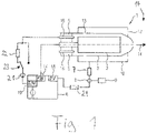
- the particle sensor 1 shows a particle sensor 1.
- the particle sensor 1 consists of a first electrode 2, which is arranged inside a second electrode 3.
- FIG. Between the first electrode 2 and the second electrode 3 there is an exhaust gas 17 of an internal combustion engine, not shown, which contains soot particles.
- the concentration of the soot particles in the exhaust gas 17 is to be measured by the particle sensor 1 .
- a measuring voltage is used for this applied between the first electrode 2 and the second electrode 3 by a power supply 6 .
- This voltage results from a first electrical potential applied to the first electrode 2 and a second electrical potential applied to the second electrode 3 .
- the first electrode 2 is electrically insulated from the second electrode 3 with the aid of an insulating body 5 .
- the insulating body 5 can be constructed, for example, as a disk made of a ceramic material.
- a guard electrode 16 which is electrically insulated from the first electrode 2 and the second electrode 3, is arranged in the particle sensor 1, which is preferably attached to the insulating body 5 and is primarily used to stabilize the voltage conditions and the electrical potentials in the particle sensor 1 and ensures this that in the measurement operation of the particle sensor 1 any electrical leakage currents between the first electrode 2 and the second electrode 3 can be derived.
- a protective cap 10 can also be seen, which is used to guide the exhaust gas flow 17 through the particle sensor 1 in a targeted manner.
- the exhaust gases can, for example, penetrate through a first opening 12 in the protective cap into the soot sensor 1 and flow through a second opening 13 formed in the second electrode 3 into a measuring area, where the particle content in the exhaust gas is measured between the first electrode 2 and the second electrode 3 can be.
- the exhaust gas flow 17 then leaves the particle sensor 1 through a third opening 14 provided in the second electrode 3 and is fed back into the main exhaust gas flow 17 .
- a guard potential 19 can be applied to the guard electrode 16 by means of the voltage supply 6 .
- a current can be measured before the dew point release time, which current can be evaluated as an indicator for a dew point release of the particle sensor 1.
- the leakage current is determined by the voltage at the first electrode 2 (1,000 V in this example) via the moist Insulator 5 driven towards the guard electrode 16, which is slightly biased against the ground potential of 0 V at the second electrode 3 in this example with 0.5 V. Only when this leakage flow drops significantly, ie by at least one power of ten, after the start of the cold internal combustion engine can it be concluded that the particle sensor 1 has dried completely and a dew point release can take place.
- the first electrical potential 14 applied to the first electrode 2 is preferably set far above the second electrical potential 18 applied to the second electrode 3 and far above the guard potential 19 applied to the guard electrode 16 .
- any first leakage currents that may be present flow from the first electrode 2 to the guard electrode 16 and are discharged there.
- guard potential 19 of the guard electrode 16 is preferably set slightly above the second potential 18 of the second electrode 3 . As a result, any second leakage currents that may be present flow from the guard electrode 16 to the second electrode 3.
- the first electrode is at a very high potential, e.g. B. 1,000 V
- the second electrode 3 to ground potential, d. H. to 0 V
- the guard electrode 16 to a slightly elevated potential, e.g. B. to 0.5 V.
- a first electrical limiting resistor 22 is arranged between the voltage supply 6 and the guard electrode 16 and can be switched on by means of a switch 23 .
- the first electrical limiting resistor 22 is permanently provided between the voltage supply 6 and the guard electrode 16 . From the first electrode 2 via the insulating body 5 to the guard electrode 16 Flowing first leakage currents can be detected by means of a first current measuring element 21.
- the first electrical limiting resistor 22 is a separate electrical resistor that is a separate component and is independent of the inherent internal resistances of the multiple components, such as. B. guard electrode 16, first electrode 2, second electrode 3 and insulating body 5, the particle sensor 1 is.
- the inherent internal resistance of the insulating body 5, over the surface of which the leakage current flows can depend on the temperature of the insulating body 5, the degree of surface contamination of the insulating body 5 or the material of the insulating body 5.
- the first limiting resistance 22 is an additional, separate and independent electrical resistance to this inherent internal resistance.
- An electrical resistor 7 is provided between the voltage supply 6 and the second electrode 3, which is of high resistance in the embodiment shown, in order to measure the relatively small currents which form between the first electrode 2 and the second electrode 3 due to the soot particles 4 can. These second leakage currents are measured by a second current measuring element 8 which is connected to evaluation electronics 9 .
- a second electrical limiting resistor 24 is connected between the power supply 6 and the second electrode 3, which, like the first electrical limiting resistor 22, is an electrical resistor that is separate from the internal resistance of the components of the particle sensor 1.
- the second leakage currents flowing from the guard electrode 16 via the insulating body 5 to the second electrode 3 can be detected using the second current measuring element 8 .
- the first electrical limiting resistor 22 and/or the second electrical limiting resistor has a resistance ranging from 0.1 G ⁇ to approximately 10 G ⁇ .
- the voltage that is applied between the first electrode 2 and the second electrode 3 is relatively high in order to obtain usable measurement currents. Such a voltage is between 100 V and 3,000 V and is therefore relatively expensive to control.
- water deposits on the first electrode 2 and the second electrode 3 and on the insulating body 5 can lead to a complete falsification of the particle measurement.
- the first and second leakage currents flowing via the insulating body 5 can cause excessive corrosion of the components of the particle sensor 1 and also lead to electromigration or solder migration in the solder connections of the particle sensor 1 . Therefore, the particle sensor 1 must be completely dry before starting the measurement, which can be signaled by the so-called dew point release.
- Soot particles that are transported through an exhaust pipe in the exhaust gas stream 17 of the internal combustion engine can penetrate into the particle sensor 1 integrated in the exhaust system.
- the soot particles get into an electrical field that forms between the first electrode 2 and the second electrode 3 due to the applied electrical voltage.
- electrically charged particles are formed, which are accelerated in the direction of the opposite electrode and, as a result of impact ionization, lead to an avalanche-like formation of charge carriers.
- this charge carrier avalanche reaches an electrode surface, a very high current can be measured, which can be evaluated well and which is proportional to the number of charged particles in the exhaust gas.
- the first leakage currents are diverted from the first electrode 2 to the guard electrode 16 by applying the first potential 14 to the first electrode 2 and applying the significantly smaller guard potential 19 to the guard electrode 16 . Also will by applying the guard potential 19 to the guard electrode 16 and by applying the second potential 18 to the second electrode 3, the second leakage currents are almost completely diverted from the guard electrode 16 to the second electrode 3.
- the guard electrode 16 is integrated into the ceramic insulating body 5 of the particle sensor 1 .
- the insulating body 5 does not necessarily have to be made of ceramic. It is also conceivable, for. B. to use a heat-resistant plastic or other insulating materials such. B. Materials from the element carbon in a corresponding crystal lattice structure, which leads to a high level of insulation.
- the first and/or second leakage currents can lead to what is known as electromigration or solder migration in solder connections in the particle sensor 1, by means of which, for example, the first electrode 2 is connected to the insulating body 5.
- the electromigration or solder migration can lead to the solder connections coming loose and/or the components of the particle sensor 1 corrode unnecessarily severely.
- the first electrical limiting resistor 22 which is designed to limit the first leakage current flowing between the first electrode 2 and the guard electrode 16 via the insulating body 5 to a first leakage current limiting value, is switched on during the measurement operation of the particle sensor 1.
- the first leakage current limitation value is approximately 1 ⁇ A/cm 2 , for example, and is preferably significantly smaller than a maximum first leakage current that would flow at maximum via the insulating body 5 without such a first limiting resistor 22 between the first electrode 2 and the guard electrode 16 .
- the second limiting resistor 24 can be designed to limit the second leakage current flowing between the second electrode 3 and the guard electrode 16 via the insulating body 5 to a second leakage current limiting value.
- the second leakage current limiting value is approximately 1 ⁇ A/cm 2 , for example, and is preferably significantly smaller than a second leakage current that would flow at maximum via the insulating body 5 without such a second limiting resistor 24 between the second electrode 3 and the guard electrode 16 .
- the first or second leakage current limiting value is selected in such a way that it is greater than a first or second leakage current threshold value. If the first or second leakage current exceeds the first or second leakage current limitation value, but remains below the first or second leakage current limitation value, the measurement operation of the particle sensor 1 is interrupted according to the invention, for example for a predetermined first or second period of time. After the first or second period of time has elapsed, all potentials are applied again by means of the voltage supply, so that the particle sensor 1 is again ready for measurement. If the first or second leakage current has fallen below the associated first or second leakage current threshold value again after the predetermined first or second period of time has elapsed, the particle sensor 1 can again be operated in the standard manner. If not, the measurement operation of particle sensor 1 continues to be interrupted until the first or second leakage current has fallen below the associated first or second leakage current threshold value.
- a method for operating an electrostatic particle sensor designed to detect the particle concentration in the exhaust gas of an internal combustion engine can be provided.
- the particle sensor has a first electrode, a second electrode that is electrically insulated from the first electrode by means of an insulating body, a guard electrode that is electrically insulated from the first electrode and the second electrode by means of the insulating body, and a voltage supply that is designed to supply a first applying electrical potential to the first electrode, applying a second electrical potential to the second electrode in such a way that an electrical voltage is produced between the first electrode and the second electrode, and applying an electrical guard potential to the guard electrode.
- Such an alternative method comprises applying the first electrical potential to the first electrode, applying the second electrical potential to the second electrode and applying the electrical guard potential to the guard electrode. Furthermore, such an alternative method comprises detecting a leakage current flowing via the insulating body and disconnecting the first electrical potential from the first electrode, disconnecting the second electrical potential from the second electrode and disconnecting the electrical guard potential from the guard electrode when the detected Leakage current exceeds a predetermined leakage current threshold.
- the first electrode, the second electrode and the guard electrode are separated from the respectively associated potential for a predetermined period of time. After this predetermined period of time has elapsed, the associated potentials are applied again to the first electrode, the second electrode and the guard electrode, and the leakage current flowing through the insulating body is recorded again. If this detected leakage flow is then again below the leakage flow threshold value, the particle sensor can be switched to the measuring mode and the actual particle measurement can take place. However, if the detected leakage current is then again below the leakage current threshold value
- the alternative method for operating an electrostatic particle sensor is based on, instead of limiting the first or second leakage current, detecting the first or second leakage current quantitatively and then interrupting the measuring operation of the particle sensor 1 when the first or second leakage current exceeds a predetermined first or exceeds the second leakage current limit value. If this is the case, the measuring operation of the particle sensor 1 is interrupted until the first or second leakage current has fallen below the associated first or second leakage current threshold value again.
- the measuring operation of the particle sensor 1 is interrupted for a predetermined first or second period of time, e.g. B. for about 30 s. After the end of the predetermined first or second period of time is switched back to the measurement mode by applying all electrical potentials of the particle sensor. If the first or second leakage flow is then below the associated first or second leakage flow limitation value, the particle measurement can be continued as usual. However, if the first or second leakage flow has not yet fallen below the associated first or second leakage flow limiting value, the measurement operation of the particle sensor 1 should continue to be interrupted, since otherwise the corrosion of the components of the particle sensor 1 can be unnecessarily large. Only when the first or second leakage flow has dropped below the associated first or second leakage flow limitation value is the measurement operation of the particle sensor 1 started.
Landscapes
- Chemical & Material Sciences (AREA)
- Physics & Mathematics (AREA)
- General Physics & Mathematics (AREA)
- Combustion & Propulsion (AREA)
- Engineering & Computer Science (AREA)
- Biochemistry (AREA)
- Analytical Chemistry (AREA)
- General Health & Medical Sciences (AREA)
- Life Sciences & Earth Sciences (AREA)
- Immunology (AREA)
- Pathology (AREA)
- Health & Medical Sciences (AREA)
- Dispersion Chemistry (AREA)
- Other Investigation Or Analysis Of Materials By Electrical Means (AREA)
- Investigating Or Analyzing Materials By The Use Of Electric Means (AREA)
Description
- Die Erfindung betrifft ein Verfahren zum Betreiben eines elektrostatischen Partikelsensors sowie eine elektrostatischen Partikelsensor.
- Die Verringerung von Abgasemissionen bei Kraftfahrzeugen ist ein wichtiges Ziel bei der Entwicklung neuer Kraftfahrzeuge. Daher werden Verbrennungsprozesse in Brennkraftmaschinen thermodynamisch optimiert, so dass der Wirkungsgrad der Brennkraftmaschine deutlich verbessert wird. Im Kraftfahrzeugbereich werden Dieselmotoren eingesetzt, die, bei moderner Bauart, einen sehr hohen Wirkungsgrad aufweisen. Der Nachteil dieser Verbrennungstechnik gegenüber optimierten Otto-Motoren ist jedoch ein deutlich erhöhter Ausstoß von Ruß bzw. Partikeln. Der Ruß ist besonders durch die Anlagerung polyzyklischer Aromate stark krebserregend, worauf mit verschiedenen Vorschriften bereits reagiert wurde. So wurden beispielsweise Abgas-Emissionsnormen mit Höchstgrenzen für die Rußemission erlassen. Um die Abgas-Emissionsnormen flächendeckend für Kraftfahrzeuge mit Dieselmotoren erfüllen zu können, besteht die Notwendigkeit, preisgünstige Sensoren herzustellen, die den Rußgehalt im Abgasstrom des Kraftfahrzeuges zuverlässig messen.
- Der Einsatz derartiger Partikel- oder Rußsensoren dient der Messung des aktuell ausgestoßenen Rußes, damit dem Motormanagement in einem Kraftfahrzeug in einer aktuellen Fahrsituation Informationen zukommen, um mit regelungstechnischen Anpassungen die Emissionswerte zu reduzieren. Darüber hinaus kann mit Hilfe der Partikelsensoren eine aktive Abgasreinigung durch Abgas-Rußfilter eingeleitet werden oder eine Abgasrückführung zur Brennkraftmaschine erfolgen. Im Falle der Rußfilterung werden regenerierbare Filter verwendet, die einen wesentlichen Teil des Rußgehaltes aus dem Abgas herausfiltern. Benötigt werden Partikelsensoren für die Detektion von Ruß bzw. Partikeln, um die Funktion der Rußfilter zu überwachen bzw. um deren Regenerationszyklen zu steuern.
- Partikelsensoren werden weiterhin zur Überprüfung der Funktionstüchtigkeit von Partikelfiltern eingesetzt. Dabei wird ein Partikelsensor im Abgasstrang einer Brennkraftmaschine bevorzugt stromabwärts eines Partikelsensors angeordnet. Überschreitet die Partikelmenge einen vorbestimmten Schwellenwert, kann auf einen nicht mehr ordnungsgemäß arbeitenden Partikelfilter geschlossen werden.
- Der Stand der Technik zeigt verschiedene Ansätze zur Detektion von Ruß. Ein in Laboratorien weithin verfolgter Ansatz besteht in der Verwendung der Lichtstreuung durch die Rußpartikel. Diese Vorgehensweise eignet sich für aufwändige Messgeräte. Wenn versucht wird, dies auch als mobiles Sensorsystem im Abgasstrang einzusetzen, muss festgestellt werden, dass Ansätze zur Realisierung eines optischen Sensors in einem Kraftfahrzeug mit sehr hohen Kosten verbunden sind. Weiterhin bestehen ungelöste Probleme bezüglich der Verschmutzung der benötigten optischen Fenster durch Verbrennungsabgase.
- Die
DE 195 36 705 Al offenbart eine Vorrichtung zur Messung von Rußpartikeln, wobei ein elektrisches Feld zwischen einer von dem Gasstrom durchströmten Mantel-Elektrode und einer Innen-Elektrode innerhalb dieser Mantel-Elektrode durch Anlegen einer konstanten elektrischen Gleichspannung erzeugt wird und der Ladestrom zur Aufrechterhaltung der konstanten Gleichspannung zwischen Mantel-Elektrode und Innen-Elektrode gemessen wird. - Die
US 2013 / 0219990 A1 beschreibt einen elektrostatischen Partikelsensor. - Aus der
US 2010 / 0005880 A1 ist eine Vorrichtung zum Bestimmen und/oder Überwachen einer Prozessvariable eines Mediums in einem Behälter bekannt. - Ein Problem, das bei der Messung von Partikeln mit Hilfe von elektrostatischen Partikelsensoren im Abgasstrang eines Kraftfahrzeugs besteht, ist, dass ein kalter Partikelsensor, zum Beispiel nach dem Start eines erkalteten Verbrennungsmotors, nicht zur Partikelmessung verwendet werden kann, da sich Kondenswasser aus dem Abgasstrom auf und in dem Rußsensor ablagert und diesen zunächst unstabil für einen Hochspannungsbetrieb macht, was eine zuverlässige Partikelmessung ausschließt. Im Abgas eines Verbrennungsmotors ist immer ein hoher Anteil von Wasser in der Gasphase vorhanden, da die Kohlenwasserstoffe zum Beispiel aus dem Dieselkraftstoff vorwiegend zu Wasser und Kohlendioxyd verbrennen. Solange der Partikelsensor kalt ist, kondensiert das Wasser aus dem Abgas zu flüssigem Wasser auf den Elektroden und dem Isolationskörper und stört damit die Partikelmessung nachhaltig. Daher sollte mit dem Beginn der Partikelmessung so lange gewartet werden, bis der Partikelsensor derart warm geworden ist, dass kein Wasser aus dem Abgasstrom mehr auskondensieren kann und das schon auskondensierte Wasser aus dem Partikelsensor abgetrocknet ist. Zu diesem Zeitpunkt erfolgt die sogenannte Taupunktfreigabe für den Partikelsensor. Ausschließlich anhand von Motormodellen in Verbindung mit einer Temperaturmessung im Abgasstrom kann nur eine sehr ungenaue Taupunktfreigabe erfolgen, da die vollständige Trocknung des Rußsensors von sehr vielen Faktoren (zum Beispiel Umgebungstemperatur des Fahrzeuges, Luftfeuchtigkeit der Ansaugluft, Gasmassenstrom im Abgasstrang) abhängt.
- Die auf den isolierenden Bauteilen kondensierte Feuchtigkeit kann die elektrisch leitenden Bauteile ungewollt elektrisch miteinander verbinden bzw. kurzschließen und dadurch elektrische Leckageströme verursachen. Diese elektrischen Leckageströme können sich nachteilig auf beispielsweise Lotverbindungen innerhalb des Partikelsensors auswirken, insbesondere in solchen Lotverbindungen eine sogenannte Elektromigration bzw. Lotmigration hervorrufen, was zu einer Verschlechterung der Dauerhaftigkeit der Lotverbindung führen kann. Beispielsweise sind die isolierenden Bauteile mittels Lotverbindungen mit den elektrisch leitenden Bauteilen verbunden.
- Ferner führt die Elektromigration bzw. Lotmigration dazu, dass sich Ionen teilweise aus der Lotverbindung lösen und sich auf der Oberfläche des Isolationskörpers ablagern können. Eine so auf der Oberfläche des Isolationskörpers abgelagerte Schicht kann die unterschiedlichen Elektroden kurzschließen und folglich erhöhte Leckageströme verursachen.
- Die Elektromigration oder Lotmigration wird insbesondere durch eine anliegende elektrische Spannung und der Feuchtigkeit auf den isolierenden Bauteilen gefördert. Ferner können die im Abgas vorherrschenden hohen Temperaturen die Elektromigration oder Lotmigration begünstigen. Die Elektromigration oder Lotmigration kann also zu erhöhter Korrosion der Bauteile des Partikelsensors führen.
- Es ist eine Aufgabe der vorliegenden Erfindung, ein Verfahren zum Betreiben eines elektrostatischen Partikelsensor sowie einen elektrostatischen Partikelsensor vorzusehen, bei dem die Gefahr von Elektromigration oder Lotmigration reduziert ist und eine Korrosion der Bauteile des Partikelsensors zumindest teilweise verhindert wird.
- Die Aufgabe wird mit dem Verfahren gemäß unabhängigem Anspruch 1 und mit dem elektrostatischen Partikelsensor gemäß unabhängigem Anspruch 9 gelöst. Bevorzugte und vorteilhafte Ausgestaltungen sind in den Unteransprüchen angegeben.
- In einem ersten Aspekt betrifft die vorliegende Erfindung ein Verfahren zum Betreiben eines zum Erfassen der Partikelkonzentration im Abgas einer Brennkraftmaschine ausgebildeten elektrostatischen Partikelsensors, der eine erste Elektrode, eine von der ersten Elektrode mittels eines Isolationskörpers elektrisch isolierte zweite Elektrode, eine von der ersten Elektrode und der zweiten Elektrode mittels des Isolationskörpers elektrisch isolierte Guardelektrode und eine Spannungsversorgung aufweist, die dazu ausgebildet ist, im Messbetrieb des Partikelsensors ein erstes elektrisches Potential an der ersten Elektrode anzulegen, ein zweites elektrisches Potential an der zweiten Elektrode derart anzulegen, dass eine elektrische Spannung zwischen der ersten Elektrode und der zweiten Elektrode entsteht, und ein elektrisches Guardpotential an der Guardelektrode anzulegen. Das erfindungsgemäße Verfahren umfasst ein Anlegen des ersten elektrischen Potentials an der ersten Elektrode, Anlegen des zweiten elektrischen Potentials an der zweiten Elektrode und Anlegen des elektrischen Guardpotentials an der Guardelektrode, und ein Begrenzen eines zwischen der ersten Elektrode und der Guardelektrode über den Isolationskörper fließenden ersten Leckagestroms auf einen ersten Leckagestrombegrenzungswert mittels eines zwischen der Guardelektrode und der Spannungsversorgung angeordneten ersten elektrischen Begrenzungswiderstands.
- Der erste elektrische Begrenzungswiderstand ist dabei ein separater elektrischer Widerstand, der ein separates Bauteil ist und der unabhängig von den inhärenten Innenwiderständen der mehreren Bauteile, wie z. B. Guardelektrode, erste Elektrode, zweite Elektrode und Isolationskörper, des Partikelsensors 1 ist.
- Folglich basiert die vorliegende Erfindung zumindest teilweise darauf, die über den Isolationskörper fließenden Leckageströme auf einen vorbestimmten Leckagestrombegrenzungswert zu begrenzen, wodurch die Korrosion der Bauteile des Partikelsensors 1 zumindest teilweise reduziert werden kann. Der vorbestimmte Leckagestrombegrenzungswert ist dabei deutlich kleiner als der maximal strömende Leckagestrom, der sich aufgrund der angelegten Spannungspotentiale maximal ergeben kann. Das Begrenzen der Leckageströme erfolgt dabei mittels zumindest eines elektrischen Begrenzungswiderstands.
- In einer bevorzugten Ausgestaltung umfasst das Verfahren ferner ein Begrenzen eines zwischen der Guardelektrode und der zweiten Elektrode über den Isolationskörper fließenden zweiten Leckagestroms mittels eines zwischen der zweiten Elektrode und der Spannungsversorgung angeordneten zweiten elektrischen Begrenzungswiderstands.
- Vorteilhafterweise umfasst das erfindungsgemäße Verfahren ferner ein Erfassen des ersten Leckagestroms, der über den Isolationskörper zwischen der ersten Elektrode und der Guardelektrode fließt, und ein Trennen der ersten Elektrode vom ersten elektrischen Potential sowie ein Trennen der Guardelektrode vom Guardpotential, wenn der erfasste erste Leckagestrom einen vorbestimmten ersten Leckagestromschwellenwert überschreitet. Vorzugsweise erfolgen das Trennen der ersten Elektrode vom ersten elektrischen Potential und das Trennen der Guardelektrode vom Guardpotential solange, bis der erfasste erste Leckagestrom den vorbestimmten ersten Leckagestromschwellenwert wieder unterschreitet. Weiterhin ist es bevorzugt, dass das Trennen der ersten Elektrode vom ersten elektrischen Potential und das Trennen der Guardelektrode vom Guardpotential jeweils für zumindest eine erste vorbestimmt Zeitspanne erfolgt. Vorzugsweise umfasst das erfindungsgemäße Verfahren ferner ein Erfassen eines zweiten Leckagestroms, der über den Isolationskörper zwischen der zweiten Elektrode und der Guardelektrode fließt, und ein Trennen der Guardelektrode vom Guardpotential und ein Trennen der zweiten Elektrode vom zweiten elektrischen Potential, wenn der erfasste zweite Leckagestrom einen vorbestimmten zweiten Leckagestromschwellenwert überschreitet. Vorzugsweise erfolgen das Trennen der Guardelektrode vom Guardpotential und das Trennen der zweiten Elektrode vom zweiten elektrischen Potential solange, bis der erfasste zweite Leckagestrom den vorbestimmten zweiten Leckagestromschwellenwert wieder unterschreitet. Dabei ist es bevorzugt, dass das Trennen der Guardelektrode vom Guardpotential und das Trennen der zweiten Elektrode vom zweiten elektrischen Potential jeweils für zumindest eine zweite vorbestimmte Zeitspanne erfolgt.
- Gemäß einem weiteren Aspekt der vorliegenden Erfindung ist ein elektrostatischer Partikelsensor zum Erfassen der Partikelkonzentration im Abgas einer Brennkraftmaschine vorgesehen. Der erfindungsgemäße Partikelsensor weist eine erste Elektrode, eine von der ersten Elektrode mittels eines Isolationskörpers elektrisch isolierte zweite Elektrode, eine von der ersten Elektrode und der zweiten Elektrode mittels des Isolationskörpers elektrisch Isolierte Guardelektrode, eine Spannungsversorgung, die dazu ausgebildet ist, ein erstes elektrisches Potential an der ersten Elektrode anzulegen, ein zweites elektrisches Potential an der zweiten Elektrode derart anzulegen, dass eine elektrischen Spannung zwischen der ersten Elektrode und der zweiten Elektrode entsteht, und ein elektrisches Guardpotential an der Guardelektrode anzulegen, und einen zwischen der Guardelektrode und der Spannungsversorgung angeordneten ersten elektrischen Begrenzungswiderstand zum Begrenzen eines zwischen der ersten Elektrode und der Guardelektrode über den Isolationskörper fließenden ersten Leckagestroms auf.
- Bevorzugt weist der erfindungsgemäße elektrostatische Partikelsensor ferner einen zwischen der zweiten Elektrode und der Spannungsversorgung angeordneten zweiten elektrischen Begrenzungswiderstand zum Begrenzen eines zwischen der Guardelektrode und der zweiten Elektrode über den Isolationskörper fließenden zweiten Leckagestroms auf.
- Alternativ oder zusätzlich kann der über den Isolationskörper fließende Leckagestrom aktiv auf einen niedrigen Wert, der kleiner als der vorbestimmte Leckagestromschwellenwert ist, gesteuert bzw. geregelt werden. Die Regelung kann dabei vorzugsweise mittels MOSFET erfolgen.
- Weitere Aufgaben und Merkmale der vorliegenden Erfindung werden dem Fachmann durch Ausüben der beschriebenen Lehre und durch Betrachten der einzigen beiliegenden
Fig. 1 ersichtlich, in der einen erfindungsgemäßer Partikelsensor dargestellt ist. -
Fig. 1 zeigt einen Partikelsensor 1. Der Partikelsensor 1 besteht aus einer ersten Elektrode 2, die im Inneren einer zweiten Elektrode 3 angeordnet ist. Zwischen der ersten Elektrode 2 und der zweiten Elektrode 3 befindet sich ein Abgas 17 einer nicht dargestellten Brennkraftmaschine, in dem Rußpartikel enthalten sind. Die Konzentration der Rußpartikel im Abgas 17 soll durch den Partikelsensor 1 gemessen werden. Mit anderen Worten kann gesagt werden, dass mit dem Partikelsensor 1 der Partikelgehalt im Abgasstrom 17 bestimmt werden soll. Dazu wird eine Messspannung durch eine Spannungsversorgung 6 zwischen der ersten Elektrode 2 und der zweiten Elektrode 3 angelegt. Diese Spannung resultiert aus einem ersten elektrischen Potential, das an die erste Elektrode 2 angelegt wird, und einem zweiten elektrischen Potential, das an die zweite Elektrode 3 angelegt wird. Die erste Elektrode 2 ist von der zweiten Elektrode 3 mithilfe eines Isolationskörpers 5 elektrisch isoliert. Der Isolationskörper 5 kann zum Beispiel als Scheibe aus einem keramischen Material aufgebaut sein. - Darüber hinaus ist im Partikelsensor 1 eine von der ersten Elektrode 2 und der zweiten Elektrode 3 elektrisch isolierte Guardelektrode 16 angeordnet, die vorzugsweise am Isolationskörper 5 angebracht ist und in erster Linie zur Stabilisierung der Spannungsverhältnisse und der elektrischen Potentiale im Partikelsensor 1 genutzt wird und dafür sorgt, dass im Messbetrieb des Partikelsensors 1 etwaige elektrische Leckageströme zwischen der erste Elektrode 2 und der zweiten Elektrode 3 abgeleitet werden können.
- In der
Fig. 1 ist ferner eine Schutzkappe 10 zu erkennen, die zur gezielten Führung des Abgasstroms 17 durch den Partikelsensor 1 dient. Die Abgase können beispielsweise durch eine erste Öffnung 12 in der Schutzkappe in den Rußsensor 1 eindringen und über eine in der zweiten Elektrode 3 gebildeten zweiten Öffnung 13 in einen Messbereich strömen, wo zwischen der ersten Elektrode 2 und der zweiten Elektrode 3 der Partikelgehalt im Abgas gemessen werden kann. Danach verlässt der Abgasstrom 17 durch eine in der zweiten Elektrode 3 vorgesehene dritte Öffnung 14 den Partikelsensor 1 und wird zurück in den Hauptabgasstrom 17 geführt. - Im Messbetrieb des Partikelsensors 6 kann mittels der Spannungsversorgung 6 ein Guardpotential 19 an der Guardelektrode 16 angelegt werden. Mit der Guardelektrode 16 kann vor dem Zeitpunkt der Taupunktfreigabe ein Strom gemessen werden, der als Indikator für eine Taupunktfreigabe des Partikelsensors 1 ausgewertet werden kann. Der Leckagestrom wird von der Spannung an der ersten Elektrode 2 (in diesem Beispiel 1.000 V) über den feuchten Isolationskörper 5 hin zur Guardelektrode 16 getrieben, die in diesen Beispiel mit 0,5 V etwas gegen das Massepotential von 0 V an der zweiten Elektrode 3 vorgespannt ist. Erst wenn dieser Leckagestrom deutlich, also um mindestens eine Zehnerpotenz, nach dem Start des kalten Verbrennungsmotors absinkt, kann auf eine vollständige Trocknung des Partikelsensors 1 geschlossen werden und eine Taupunktfreigabe erfolgen.
- Elektrische Leckageströme sind also unerwünschte Ströme, die infolge unzureichender Isolationseigenschaften über den Isolationskörper 5 im Messbetrieb des Partikelsensors 1 fließen und damit die Messergebnisse des Partikelsensors 1 wesentlich verfälschen können. Im Messbetrieb des Partikelsensors 1 wird vorzugsweise das an der ersten Elektrode 2 angelegte erste elektrische Potential 14 weit oberhalb des an der zweiten Elektrode 3 angelegten zweiten elektrischen Potentials 18 und weit oberhalb des an der Guardelektrode 16 angelegten Guardpotentials 19 eingestellt. Dadurch fließen eventuell vorhandene erste Leckageströme von der ersten Elektrode 2 zur Guardelektrode 16 und werden dort abgeleitet.
- Ferner wird vorzugsweise das Guardpotential 19 der Guardelektrode 16 etwas oberhalb des zweiten Potentials 18 der zweiten Elektrode 3 eingestellt. Dadurch fließen eventuell vorhandene zweite Leckageströme von der Guardelektrode 16 zur zweiten Elektrode 3.
- Bei einer beispielhaften Messkonfiguration liegt die erste Elektrode auf sehr hohem Potential, z. B. 1.000 V, die zweite Elektrode 3 auf Ground-Potential, d. h. auf 0 V, und die Guardelektrode 16 auf etwas erhöhtem Potential, z. B. auf 0,5 V.
- In der
Fig. 1 ist gezeigt, dass zwischen der Spannungsversorgung 6 und der Guardelektrode 16 ein erster elektrischer Begrenzungswiderstand 22 angeordnet ist, der mittels eines Schalters 23 zuschaltbar ist. Alternativ ist der erste elektrische Begrenzungswiderstand 22 dauerhaft zwischen der Spannungsversorgung 6 und der Guardelektrode 16 vorgesehen. Die von der ersten Elektrode 2 über den Isolationskörper 5 zur Guardelektrode 16 fließenden ersten Leckageströme können mittels eines ersten Strommesselements 21 erfasst werden. - Der erste elektrische Begrenzungswiderstand 22 ist ein separater elektrischer Widerstand, der ein separates Bauteil ist und der unabhängig von den inhärenten Innenwiderständen der mehreren Bauteile, wie z. B. Guardelektrode 16, erste Elektrode 2, zweite Elektrode 3 und Isolationskörper 5, des Partikelsensors 1 ist. Beispielsweise kann der inhärente Innenwiderstand des Isolationskörpers 5, über dessen Oberfläche der Leckagestrom strömt, von der Temperatur des Isolationskörpers 5, dem Oberflächenverschmutzungsgrad des Isolationskörpers 5 oder dem Material des Isolationskörpers 5 abhängen. Der erste Begrenzungswiderstand 22 ist jedoch ein zu diesem inhärenten Innenwiderstand zusätzlicher, separater und unabhängiger elektrischer Widerstand.
- Ein elektrischer Widerstand 7 ist zwischen der Spannungsversorgung 6 und der zweiten Elektrode 3 vorgesehen, der in der gezeigten Ausgestaltung hochohmig ausgeführt ist, um die relativ kleinen Ströme zu messen, die sich aufgrund der Rußpartikel 4 zwischen der ersten Elektrode 2 und der zweiten Elektrode 3 ausbilden können. Die Messung dieser zweiten Leckageströme erfolgt durch ein zweites Strommesselement 8, das mit einer Auswerteelektronik 9 verbunden ist.
- Weiterhin ist in
Fig. 1 zu erkennen, dass zwischen der Spannungsversorgung 6 und der zweiten Elektrode 3 ein zweiter elektrischer Begrenzungswiderstand 24 geschaltet ist, der, wie der erste elektrische Begrenzungswiderstand 22, ein vom Innenwiderstand der Bauteile des Partikelsensors 1 separater elektrischer Widerstand ist. Die von der Guardelektrode 16 über den Isolationskörper 5 zur zweiten Elektrode 3 fließenden zweiten Leckageströme können mittels des zweiten Strommesselements 8 erfasst werden. - Beispielsweise weisen der erste elektrische Begrenzungswiderstand 22 und/oder der zweite elektrische Begrenzungswiderstand einen Widerstandswert auf, der im Bereich von 0, 1 GΩ bis ungefähr 10 GΩ liegt.
- Die Spannung, die zwischen der ersten Elektrode 2 und der zweiten Elektrode 3 angelegt wird, ist relativ hoch, um verwertbare Messströme zu erhalten. Eine derartige Spannung liegt zwischen 100 V und 3.000 V und ist damit relativ aufwendig zu kontrollieren. Insbesondere Wasserablagerungen auf der ersten Elektrode 2 und der zweiten Elektrode 3 sowie auf dem Isolationskörper 5 können zu einer vollständigen Verfälschung der Partikelmessung führen. Ferner können die über den Isolationskörper 5 fließenden ersten und zweiten Leckageströme eine übermäßig große Korrosion der Bauteile des Partikelsensors 1 hervorrufen und ferner zu Elektromigration bzw. Lotmigration in den Lotverbindungen des Partikelsensors 1 führen. Daher muss der Partikelsensor 1 vor Beginn der Messung völlig abgetrocknet sein, was durch die sogenannte Taupunktfreigabe signalisiert werden kann.
- Rußpartikel, die im Abgasstrom 17 der Brennkraftmaschine durch ein Auspuffrohr transportiert werden, können in den im Abgasstrang integrierten Partikelsensor 1 eindringen. Die Rußpartikel gelangen in ein elektrisches Feld, das sich aufgrund der angelegten elektrischen Spannung zwischen der ersten Elektrode 2 und der zweiten Elektrode 3 ausbildet. Beim Überschreiten der Durchbruchsfeldstärke des Gases werden elektrisch geladene Partikel gebildet, die in Richtung der entgegengesetzten Elektrode beschleunigt werden und infolge von Stoßionisationen zu einer lavinenartigen Ausbildung von Ladungsträgern führen. Wenn diese Ladungsträgerlavine eine Elektrodenoberfläche erreicht, ist ein sehr hoher Strom messbar, der gut ausgewertet werden kann und der proportional zur Anzahl der geladenen Partikel im Abgas ist.
- Durch Anlegen des ersten Potentials 14 an die erste Elektrode 2 und Anlegen des deutlich kleineren Guardpotentials 19 an die Guardelektrode 16 werden die ersten Leckageströme von der ersten Elektrode 2 zur Guardelektrode 16 abgeleitet. Außerdem werden durch Anlegen des Guardpotentials 19 an die Guardelektrode 16 und durch Anlegen des zweiten Potentials 18 an die zweite Elektrode 3 die zweiten Leckageströme nahezu vollständig von der Guardelektrode 16 zur zweiten Elektrode 3 abgeleitet.
- Die Guardelektrode 16 ist in diesem Beispiel in den keramischen Isolationskörper 5 des Partikelsensors 1 integriert. Der Isolationskörper 5 muss jedoch nicht notwendigerweise aus einer Keramik bestehen. Es ist auch denkbar, z. B. einen hitzefesten Kunststoff einzusetzen oder andere isolierende Materialien, wie z. B. Materialien aus dem Element Kohlenstoff in einer entsprechenden Kristallgitterstruktur, die zu einer hohen Isolation führt.
- Die ersten und/oder zweiten Leckageströme können zu einer sogenannten Elektromigration bzw. Lotmigration in Lotverbindungen im Partikelsensoren 1 führen, mittels derer beispielsweise die erste Elektrode 2 mit dem Isolationskörper 5 verbunden ist. Die Elektromigration bzw. Lotmigration kann zu einem Lösen der Lotverbindungen führen und/oder die Bauteile des Partikelsensors 1 unnötig stark korrodieren.
- Erfindungsgemäß wird während des Messbetriebs des Partikelsensors 1 der erste elektrische Begrenzungswiderstand 22 zugeschaltet, der dazu ausgebildet ist, den zwischen der ersten Elektrode 2 und der Guardelektrode 16 über den Isolationskörper 5 fließenden ersten Leckagestrom auf einen ersten Leckagestrombegrenzungswert zu begrenzen. Der erste Leckagestrombegrenzungswert beträgt beispielsweise ungefähr 1 µA/cm2 und ist vorzugsweise deutlich kleiner als ein maximaler erster Leckagestrom, der ohne einem solchen ersten Begrenzungswiderstand 22 zwischen der ersten Elektrode 2 und der Guardelektrode 16 über den Isolationskörper 5 maximal fließen würde. Durch das Begrenzen des ersten Leckagestroms kann die Elektromigration bzw. Lotmigration der Lotverbindungen zumindest teilweise reduziert und die Korrosion der Bauteile des Partikelsensors zumindest teilweise vermieden werden.
- Zudem kann der zweite Begrenzungswiderstand 24 dazu ausgebildet sein, den zwischen der zweiten Elektrode 3 und der Guardelektrode 16 über den Isolationskörper 5 fließenden zweiten Leckagestrom auf einen zweiten Leckagestrombegrenzungswert zu begrenzen. Der zweite Leckagestrombegrenzungswert beträgt beispielsweise ungefähr 1 µA/cm2 und ist vorzugsweise deutlich kleiner als ein zweiter Leckagestrom, der ohne einem solchen zweiten Begrenzungswiderstand 24 zwischen der zweiten Elektrode 3 und der Guardelektrode 16 über den Isolationskörper 5 maximal fließen würde. Durch das Begrenzen des zweiten Leckagestroms kann die Elektromigration bzw. Lotmigration der Lotverbindungen zumindest teilweise reduziert und die Korrosion der Bauteile des Partikelsensors 1 zumindest teilweise vermieden werden.
- In einer weiteren Ausgestaltung ist der erste bzw. zweite Leckagestrombegrenzungswert derart gewählt, dass dieser größer als ein erster bzw. zweiter Leckagestromschwellenwert ist. Überschreitet der erste bzw. zweite Leckagestrom den ersten bzw. zweiten Leckagestrombegrenzungswert, bleibt aber gleichzeitig unterhalb des ersten bzw. zweiten Leckagestrombegrenzungswerts, wird erfindungsgemäß der Messbetrieb des Partikelsensors 1 unterbrochen, beispielsweise für eine vorbestimmte erste bzw. zweite Zeitspanne. Nach dem Ablauf der ersten bzw. zweiten Zeitspanne werden mittels der Spannungsversorgung sämtliche Potentiale erneut angelegt, so dass der Partikelsensor 1 wieder messbereit ist. Ist dann der erste bzw. zweite Leckagestrom nach dem Ablauf der vorbestimmten ersten bzw. zweiten Zeitspanne wieder unterhalb des zugehörigen ersten bzw. zweiten Leckagestromschwellenwert gesunken, kann der Partikelsensor 1 wieder standardmäßig betrieben werden. Falls nicht, wird der Messbetrieb des Partikelsensors 1 weiterhin solange unterbrochen, bis der erste bzw. zweite Leckagestrom unter den zugehörigen ersten bzw. zweiten Leckagestromschwellenwert gesunken ist.
- Gemäß einem alternativen Aspekt der vorliegenden Offenbarung kann ein Verfahren zum Betreiben eines zum Erfassen der Partikelkonzentration im Abgas einer Brennkraftmaschine ausgebildeten elektrostatischen Partikelsensors vorgesehen sein. Der Partikelsensor weist eine erste Elektrode, eine von der ersten Elektrode mittels eines Isolationskörpers elektrisch isolierte zweite Elektrode, eine von der ersten Elektrode und der zweiten Elektrode mittels des Isolationskörpers elektrisch isolierte Guardelektrode und eine Spannungsversorgung auf, die dazu ausgebildet ist, im Messbetrieb des Partikelsensors ein erstes elektrisches Potential an der ersten Elektrode anzulegen, ein zweites elektrisches Potential an der zweiten Elektrode derart anzulegen, dass eine elektrische Spannung zwischen der ersten Elektrode und der zweiten Elektrode entsteht, und ein elektrisches Guardpotential an der Guardelektrode anzulegen. Ein solches alternatives Verfahren weist ein Anlegen des ersten elektrischen Potentials an der ersten Elektrode, ein Anlegen des zweiten elektrischen Potentials an der zweiten Elektrode und ein Anlegen des elektrischen Guardpotentials an der Guardelektrode auf. Ferner weist ein solches alternatives Verfahren ein Erfassen eines über den Isolationskörper fließenden Leckagestroms und ein Trennen des ersten elektrischen Potentials von der ersten Elektrode, ein Trennen des zweiten elektrischen Potentials von der zweiten Elektrode und ein Trennen des elektrischen Guardpotentials von der Guardelektrode auf, wenn der erfasste Leckagestrom einen vorbestimmten Leckagestromschwellenwert überschreitet.
- In einer bevorzugten Ausgestaltung eines solchen alternativen Verfahrens werden die erste Elektrode, die zweite Elektrode und die Guardelektrode von dem jeweils zugeordneten Potential für eine vorbestimmte Zeitspanne getrennt. Nach Ablauf dieser vorbestimmten Zeitspanne werden an der ersten Elektrode, an der zweiten Elektrode und an der Guardelektrode wieder jeweils die zugeordneten Potentiale angelegt und nochmal der über den Isolationskörper fließende Leckagestrom erfasst. Ist dieser erfasste Leckagestrom dann wieder unterhalb des Leckagestromschwellenwerts, kann der Partikelsensor in den Messbetrieb geschaltet werden und die eigentliche Partikelmessung kann erfolgen. Ist aber der erfasste Leckagestrom dann wieder unterhalb des Leckagestromschwellenwerts
- Somit basiert das alternative Verfahren zum Betreiben eines elektrostatischen Partikelsensors darauf, anstelle des Begrenzens des ersten bzw. zweiten Leckagestroms den ersten bzw. zweiten Leckagestrom quantitativ zu erfassen und den Messbetrieb des Partikelsensors 1 dann zu unterbrechen, wenn der erste bzw. zweite Leckagestrom einen vorbestimmten ersten bzw. zweiten Leckagestrombegrenzungswert überschreitet. Ist dies der Fall, wird der Messbetrieb des Partikelsensors 1 solange unterbrochen, bis der erste bzw. zweite Leckagestrom wieder unter den zugehörigen ersten bzw. zweiten Leckagestromschwellenwert gesunken ist.
- Beispielsweise wird hierzu der Messbetrieb des Partikelsensors 1 für eine vorbestimmte erste bzw. zweite Zeitspanne unterbrochen, z. B. für ungefähr 30 s. Nach dem Ablauf der vorbestimmten ersten bzw. zweiten Zeitspanne wird durch Anlegen sämtlicher elektrischen Potentiale der Partikelsensor 1 wieder in den Messbetrieb geschaltet. Ist dann der erste bzw. zweite Leckagestrom unterhalb des zugehörigen ersten bzw. zweiten Leckagestrombegrenzungswerts, kann mit der Partikelmessung wie gewohnt fortgefahren werden. Ist aber der erste bzw. zweite Leckagestrom noch nicht unterhalb des zugehörigen ersten bzw. zweiten Leckagestrombegrenzungswerts gesunken, sollte der Messbetrieb des Partikelsensors 1 weiterhin unterbrochen bleiben, da sonst die Korrosion der Bauteile des Partikelsensors 1 unnötig groß sein kann. Erst wenn der erste bzw. zweite Leckagestrom unter den zugehörigen ersten bzw. zweiten Leckagestrombegrenzungswerts gesunken ist, wird der Messbetrieb des Partikelsensors 1 gestartet.
Claims (10)
- Verfahren zum Betreiben eines zum Erfassen der Partikelkonzentration im Abgas einer Brennkraftmaschine ausgebildeten elektrostatischen Partikelsensors (1), der eine erste Elektrode (2), eine von der ersten Elektrode (2) mittels eines Isolationskörpers (5) elektrisch isolierte zweite Elektrode (3), eine von der ersten Elektrode (2) und der zweiten Elektrode (3) mittels des Isolationskörpers (5) elektrisch isolierte Guardelektrode (16) und eine Spannungsversorgung (6) aufweist, die dazu ausgebildet ist, im Messbetrieb des Partikelsensors (1) ein erstes elektrisches Potential (14) an der ersten Elektrode (2) anzulegen, ein zweites elektrisches Potential (18) an der zweiten Elektrode (3) derart anzulegen, dass eine elektrische Spannung zwischen der ersten Elektrode (2) und der zweiten Elektrode (3) entsteht, und ein elektrisches Guardpotential (19) an der Guardelektrode (16) anzulegen, wobei das Verfahren aufweist:- Anlegen des ersten elektrischen Potentials (14) an der ersten Elektrode (2), Anlegen des zweiten elektrischen Potentials (18) an der zweiten Elektrode (3) und Anlegen des elektrischen Guardpotentials (19) an der Guardelektrode (16),dadurch gekennzeichnet, dass das Verfahren auch aufweist:- Begrenzen eines zwischen der ersten Elektrode (2) und der Guardelektrode (16) über den Isolationskörper (5) fließenden ersten Leckagestroms auf einen ersten Leckagestrombegrenzungswert mittels eines zwischen der Guardelektrode (16) und der Spannungsversorgung (6) angeordneten ersten elektrischen Begrenzungswiderstands (22).
- Verfahren nach Anspruch 1, ferner mit:- Begrenzen eines zwischen der Guardelektrode (16) und der zweiten Elektrode (3) über den Isolationskörper (5) fließenden zweiten Leckagestroms mittels eines zwischen der zweiten Elektrode (3) und der Spannungsversorgung (6) angeordneten zweiten elektrischen Begrenzungswiderstands (24).
- Verfahren nach einem der vorhergehenden Ansprüche, ferner mit:- Erfassen des ersten Leckagestroms, der über den Isolationskörper (5) zwischen der ersten Elektrode (2) und der Guardelektrode (16) fließt, und- Trennen der ersten Elektrode (2) vom ersten elektrischen Potential (14) und Trennen der Guardelektrode (16) vom Guardpotential (19) , wenn der erfasste erste Leckagestrom einen vorbestimmten ersten Leckagestromschwellenwert überschreitet.
- Verfahren nach Anspruch 3, wobei das Trennen der ersten Elektrode (2) vom ersten elektrischen Potential (14) und das Trennen der Guardelektrode (16) vom Guardpotential (19) solange erfolgt, bis der erfasste erste Leckagestrom den vorbestimmten ersten Leckagestromschwellenwert wieder unterschreitet.
- Verfahren nach Anspruch 4, wobei das Trennen der ersten Elektrode (2) vom ersten elektrischen Potential (14) und das Trennen der Guardelektrode (16) vom Guardpotential (19) jeweils für zumindest eine erste vorbestimmt Zeitspanne erfolgt.
- Verfahren nach einem der vorhergehenden Ansprüche, ferner mit:- Erfassen eines zweiten Leckagestroms, der über den Isolationskörper (5) zwischen der zweiten Elektrode (3) und der Guardelektrode (16) fließt, und- Trennen der Guardelektrode (16) vom Guardpotential (19) und Trennen der zweiten Elektrode (3) vom zweiten elektrischen Potential (18), wenn der erfasste zweite Leckagestrom einen vorbestimmten zweiten Leckagestromschwellenwert überschreitet.
- Verfahren nach Anspruch 6, wobei das Trennen der Guardelektrode (16) vom Guardpotential (19) und das Trennen der zweiten Elektrode (3) vom zweiten elektrischen Potential (18) solange erfolgen, bis der erfasste zweite Leckagestrom den vorbestimmten zweiten Leckagestromschwellenwert wieder unterschreitet.
- Verfahren nach Anspruch 7, wobei das Trennen der der Guardelektrode (16) vom Guardpotential (19) und das Trennen der zweiten Elektrode (3) vom zweiten elektrischen Potential (18) jeweils für zumindest eine zweite vorbestimmte Zeitspanne erfolgen .
- Elektrostatischer Partikelsensor (1) zum Erfassen der Partikelkonzentration im Abgas einer Brennkraftmaschine, wobei der elektrostatische Partikelsensor (1) aufweist:- eine erste Elektrode (2),- eine von der ersten Elektrode (2) mittels eines Isolationskörpers (5) elektrisch isolierte zweite Elektrode (3),- eine von der ersten Elektrode (2) und der zweiten Elektrode (3) mittels des Isolationskörpers (5) elektrisch Isolierte Guardelektrode (16),- eine Spannungsversorgung (6), die dazu ausgebildet ist, ein erstes elektrisches Potential (14) an der ersten Elektrode (2) anzulegen, ein zweites elektrisches Potential (18) an der zweiten Elektrode (2) derart anzulegen, dass eine elektrischen Spannung zwischen der ersten Elektrode (2) und der zweiten Elektrode (3) entsteht, und ein elektrisches Guardpotential (19) an der Guardelektrode (16) anzulegen,dadurch gekennzeichnet, dass der elektrostatische Partikelsensor (1) auch aufweist:- einen zwischen der Guardelektrode (16) und der Spannungsversorgung (6) angeordneten ersten elektrischen Begrenzungswiderstand (22) zum Begrenzen eines zwischen der ersten Elektrode (2) und der Guardelektrode (16) über den Isolationskörper (5) fließenden ersten Leckagestroms.
- Elektrostatischer Partikelsensor (1) nach Anspruch 9, ferner mit einem zwischen der zweiten Elektrode (3) und der Spannungsversorgung (6) angeordneten zweiten elektrischen Begrenzungswiderstand (24) zum Begrenzen eines zwischen der Guardelektrode (16) und der zweiten Elektrode (3) über den Isolationskörper (5) fließenden zweiten Leckagestroms.
Applications Claiming Priority (2)
| Application Number | Priority Date | Filing Date | Title |
|---|---|---|---|
| DE102017202859.9A DE102017202859B4 (de) | 2017-02-22 | 2017-02-22 | Verfahren zum Betreiben eines elektrostatischen Partikelsensors und elektrostatischer Partikelsensor |
| PCT/EP2018/054315 WO2018153942A1 (de) | 2017-02-22 | 2018-02-21 | Verfahren zum betreiben eines elektrostatischen partikelsensors und elektrostatischer partikelsensor |
Publications (2)
| Publication Number | Publication Date |
|---|---|
| EP3586102A1 EP3586102A1 (de) | 2020-01-01 |
| EP3586102B1 true EP3586102B1 (de) | 2022-12-21 |
Family
ID=61521489
Family Applications (1)
| Application Number | Title | Priority Date | Filing Date |
|---|---|---|---|
| EP18707885.2A Active EP3586102B1 (de) | 2017-02-22 | 2018-02-21 | Verfahren zum betreiben eines elektrostatischen partikelsensors und elektrostatischer partikelsensor |
Country Status (4)
| Country | Link |
|---|---|
| US (1) | US11119006B2 (de) |
| EP (1) | EP3586102B1 (de) |
| DE (1) | DE102017202859B4 (de) |
| WO (1) | WO2018153942A1 (de) |
Family Cites Families (4)
| Publication number | Priority date | Publication date | Assignee | Title |
|---|---|---|---|---|
| DE19536705A1 (de) | 1995-09-30 | 1997-04-03 | Guenther Prof Dr Ing Hauser | Partikel-Meßverfahren und Vorrichtung |
| DE102006047780A1 (de) * | 2006-10-06 | 2008-04-10 | Endress + Hauser Gmbh + Co. Kg | Vorrichtung zur Bestimmung und/oder Überwachung einer Prozeßgröße |
| US8671736B2 (en) | 2011-05-26 | 2014-03-18 | Emisense Technologies, Llc | Agglomeration and charge loss sensor for measuring particulate matter |
| DE102015225739B4 (de) * | 2015-12-17 | 2019-09-12 | Continental Automotive Gmbh | Verfahren zum Betreiben eines elektrostatischen Rußsensors |
-
2017
- 2017-02-22 DE DE102017202859.9A patent/DE102017202859B4/de active Active
-
2018
- 2018-02-21 WO PCT/EP2018/054315 patent/WO2018153942A1/de not_active Ceased
- 2018-02-21 US US16/487,779 patent/US11119006B2/en active Active
- 2018-02-21 EP EP18707885.2A patent/EP3586102B1/de active Active
Also Published As
| Publication number | Publication date |
|---|---|
| US20190376875A1 (en) | 2019-12-12 |
| WO2018153942A1 (de) | 2018-08-30 |
| US11119006B2 (en) | 2021-09-14 |
| EP3586102A1 (de) | 2020-01-01 |
| DE102017202859A1 (de) | 2018-08-23 |
| DE102017202859B4 (de) | 2022-06-15 |
Similar Documents
| Publication | Publication Date | Title |
|---|---|---|
| DE112010005888B4 (de) | Feinstaub-Erfassungsvorrichtung für Verbrennungsmaschinen | |
| EP2864757B1 (de) | Verfahren zur funktionskontrolle eines sensors zur detektion von teilchen und sensor zur detektion von teilchen | |
| EP3071945A1 (de) | Verfahren und vorrichtung zum betreiben eines partikelsensors | |
| DE102010030634A1 (de) | Verfahren und Vorrichtung zum Betreiben eines Partikelsensors | |
| DE102009028283A1 (de) | Verfahren und Vorrichtung zur Eigendiagnose eines Partikelsensors | |
| DE102009028319A1 (de) | Verfahren und Vorrichtung zum Betrieb eines Partikelsensors | |
| DE102011086148A1 (de) | Verfahren und Vorrichtung zum Betreiben eines resistiven Sensors im Abgaskanal einer Brennkraftmaschine | |
| EP3391024B1 (de) | Elektrostatischer russsensor | |
| EP3204750B1 (de) | Verfahren zur funktionskontrolle eines sensors zur detektion von teilchen, computerprogramm, elektronisches speichermedium und elektronisches steuergerät | |
| DE102015225739B4 (de) | Verfahren zum Betreiben eines elektrostatischen Rußsensors | |
| DE102009046315A1 (de) | Verfahren und Vorrichtung zum Betreiben eines Partikelsensors | |
| DE102017202859B4 (de) | Verfahren zum Betreiben eines elektrostatischen Partikelsensors und elektrostatischer Partikelsensor | |
| EP3894832B1 (de) | Verfahren zum betreiben eines sensors zur detektion von teilchen in einem messgas | |
| DE102010029066A1 (de) | Verfahren und Vorrichtung zur Überwachung eines resistiven Partikelsensors | |
| WO2017029074A1 (de) | VERFAHREN ZUR FUNKTIONSÜBERWACHUNG EINES ELEKTROSTATISCHEN RUßSENSORS | |
| DE102022203057A1 (de) | Verfahren zum Betreiben eines Sensors zur Erfassung mindestens einer Eigenschaft eines Messgases | |
| DE102013206092A1 (de) | Verfahren zur Auswertung der Messwerte eines Rußsensors | |
| DE102010011639A1 (de) | Rußsensor, Herstellungsverfahren eines Rußsensors sowie Betriebsverfahren eines Rußsensors | |
| DE102015214398A1 (de) | Verfahren zum Betreiben eines Sensors zur Detektion von Teilchen in einem Abgasstrang einer Brennkraftmaschine | |
| DE102013216899A1 (de) | Verfahren und Vorrichtung zum Betrieb eines sammelnden Partikelsensors | |
| WO2019120789A1 (de) | Sensoranordnung zur erfassung von partikeln eines messgases in einem messgasraum und verfahren zur erfassung von partikeln eines messgases in einem messgasraum | |
| DE112017001492T5 (de) | Detektionsvorrichtung für partikuläre Materie | |
| DE102012214974A1 (de) | Verfahren und Steuereinheit zum Betrieb eines sammelnden Partikelsensors | |
| DE102020215456A1 (de) | Verfahren zur Funktionskontrolle eines Sensors zur Detektion von Rußpartikeln in einem Abgas | |
| DE102017210625A1 (de) | Resistiver Partikelsensor |
Legal Events
| Date | Code | Title | Description |
|---|---|---|---|
| STAA | Information on the status of an ep patent application or granted ep patent |
Free format text: STATUS: UNKNOWN |
|
| STAA | Information on the status of an ep patent application or granted ep patent |
Free format text: STATUS: THE INTERNATIONAL PUBLICATION HAS BEEN MADE |
|
| PUAI | Public reference made under article 153(3) epc to a published international application that has entered the european phase |
Free format text: ORIGINAL CODE: 0009012 |
|
| STAA | Information on the status of an ep patent application or granted ep patent |
Free format text: STATUS: REQUEST FOR EXAMINATION WAS MADE |
|
| 17P | Request for examination filed |
Effective date: 20190529 |
|
| AK | Designated contracting states |
Kind code of ref document: A1 Designated state(s): AL AT BE BG CH CY CZ DE DK EE ES FI FR GB GR HR HU IE IS IT LI LT LU LV MC MK MT NL NO PL PT RO RS SE SI SK SM TR |
|
| AX | Request for extension of the european patent |
Extension state: BA ME |
|
| DAV | Request for validation of the european patent (deleted) | ||
| DAX | Request for extension of the european patent (deleted) | ||
| RAP1 | Party data changed (applicant data changed or rights of an application transferred) |
Owner name: VITESCO TECHNOLOGIES GMBH |
|
| RAP3 | Party data changed (applicant data changed or rights of an application transferred) |
Owner name: VITESCO TECHNOLOGIES GMBH |
|
| GRAP | Despatch of communication of intention to grant a patent |
Free format text: ORIGINAL CODE: EPIDOSNIGR1 |
|
| STAA | Information on the status of an ep patent application or granted ep patent |
Free format text: STATUS: GRANT OF PATENT IS INTENDED |
|
| INTG | Intention to grant announced |
Effective date: 20220324 |
|
| GRAJ | Information related to disapproval of communication of intention to grant by the applicant or resumption of examination proceedings by the epo deleted |
Free format text: ORIGINAL CODE: EPIDOSDIGR1 |
|
| STAA | Information on the status of an ep patent application or granted ep patent |
Free format text: STATUS: REQUEST FOR EXAMINATION WAS MADE |
|
| INTC | Intention to grant announced (deleted) | ||
| GRAS | Grant fee paid |
Free format text: ORIGINAL CODE: EPIDOSNIGR3 |
|
| STAA | Information on the status of an ep patent application or granted ep patent |
Free format text: STATUS: GRANT OF PATENT IS INTENDED |
|
| GRAP | Despatch of communication of intention to grant a patent |
Free format text: ORIGINAL CODE: EPIDOSNIGR1 |
|
| RAP1 | Party data changed (applicant data changed or rights of an application transferred) |
Owner name: EMISENSE TECHNOLOGIES LLC |
|
| RAP3 | Party data changed (applicant data changed or rights of an application transferred) |
Owner name: EMISENSE TECHNOLOGIES LLC |
|
| GRAA | (expected) grant |
Free format text: ORIGINAL CODE: 0009210 |
|
| STAA | Information on the status of an ep patent application or granted ep patent |
Free format text: STATUS: THE PATENT HAS BEEN GRANTED |
|
| INTG | Intention to grant announced |
Effective date: 20221025 |
|
| AK | Designated contracting states |
Kind code of ref document: B1 Designated state(s): AL AT BE BG CH CY CZ DE DK EE ES FI FR GB GR HR HU IE IS IT LI LT LU LV MC MK MT NL NO PL PT RO RS SE SI SK SM TR |
|
| REG | Reference to a national code |
Ref country code: GB Ref legal event code: FG4D Free format text: NOT ENGLISH |
|
| REG | Reference to a national code |
Ref country code: CH Ref legal event code: EP |
|
| REG | Reference to a national code |
Ref country code: DE Ref legal event code: R096 Ref document number: 502018011268 Country of ref document: DE |
|
| REG | Reference to a national code |
Ref country code: AT Ref legal event code: REF Ref document number: 1539329 Country of ref document: AT Kind code of ref document: T Effective date: 20230115 |
|
| REG | Reference to a national code |
Ref country code: IE Ref legal event code: FG4D Free format text: LANGUAGE OF EP DOCUMENT: GERMAN |
|
| REG | Reference to a national code |
Ref country code: LT Ref legal event code: MG9D |
|
| REG | Reference to a national code |
Ref country code: NL Ref legal event code: MP Effective date: 20221221 |
|
| PG25 | Lapsed in a contracting state [announced via postgrant information from national office to epo] |
Ref country code: SE Free format text: LAPSE BECAUSE OF FAILURE TO SUBMIT A TRANSLATION OF THE DESCRIPTION OR TO PAY THE FEE WITHIN THE PRESCRIBED TIME-LIMIT Effective date: 20221221 Ref country code: NO Free format text: LAPSE BECAUSE OF FAILURE TO SUBMIT A TRANSLATION OF THE DESCRIPTION OR TO PAY THE FEE WITHIN THE PRESCRIBED TIME-LIMIT Effective date: 20230321 Ref country code: LT Free format text: LAPSE BECAUSE OF FAILURE TO SUBMIT A TRANSLATION OF THE DESCRIPTION OR TO PAY THE FEE WITHIN THE PRESCRIBED TIME-LIMIT Effective date: 20221221 Ref country code: FI Free format text: LAPSE BECAUSE OF FAILURE TO SUBMIT A TRANSLATION OF THE DESCRIPTION OR TO PAY THE FEE WITHIN THE PRESCRIBED TIME-LIMIT Effective date: 20221221 |
|
| PG25 | Lapsed in a contracting state [announced via postgrant information from national office to epo] |
Ref country code: RS Free format text: LAPSE BECAUSE OF FAILURE TO SUBMIT A TRANSLATION OF THE DESCRIPTION OR TO PAY THE FEE WITHIN THE PRESCRIBED TIME-LIMIT Effective date: 20221221 Ref country code: LV Free format text: LAPSE BECAUSE OF FAILURE TO SUBMIT A TRANSLATION OF THE DESCRIPTION OR TO PAY THE FEE WITHIN THE PRESCRIBED TIME-LIMIT Effective date: 20221221 Ref country code: HR Free format text: LAPSE BECAUSE OF FAILURE TO SUBMIT A TRANSLATION OF THE DESCRIPTION OR TO PAY THE FEE WITHIN THE PRESCRIBED TIME-LIMIT Effective date: 20221221 Ref country code: GR Free format text: LAPSE BECAUSE OF FAILURE TO SUBMIT A TRANSLATION OF THE DESCRIPTION OR TO PAY THE FEE WITHIN THE PRESCRIBED TIME-LIMIT Effective date: 20230322 |
|
| PG25 | Lapsed in a contracting state [announced via postgrant information from national office to epo] |
Ref country code: NL Free format text: LAPSE BECAUSE OF FAILURE TO SUBMIT A TRANSLATION OF THE DESCRIPTION OR TO PAY THE FEE WITHIN THE PRESCRIBED TIME-LIMIT Effective date: 20221221 |
|
| PG25 | Lapsed in a contracting state [announced via postgrant information from national office to epo] |
Ref country code: SM Free format text: LAPSE BECAUSE OF FAILURE TO SUBMIT A TRANSLATION OF THE DESCRIPTION OR TO PAY THE FEE WITHIN THE PRESCRIBED TIME-LIMIT Effective date: 20221221 Ref country code: RO Free format text: LAPSE BECAUSE OF FAILURE TO SUBMIT A TRANSLATION OF THE DESCRIPTION OR TO PAY THE FEE WITHIN THE PRESCRIBED TIME-LIMIT Effective date: 20221221 Ref country code: PT Free format text: LAPSE BECAUSE OF FAILURE TO SUBMIT A TRANSLATION OF THE DESCRIPTION OR TO PAY THE FEE WITHIN THE PRESCRIBED TIME-LIMIT Effective date: 20230421 Ref country code: ES Free format text: LAPSE BECAUSE OF FAILURE TO SUBMIT A TRANSLATION OF THE DESCRIPTION OR TO PAY THE FEE WITHIN THE PRESCRIBED TIME-LIMIT Effective date: 20221221 Ref country code: EE Free format text: LAPSE BECAUSE OF FAILURE TO SUBMIT A TRANSLATION OF THE DESCRIPTION OR TO PAY THE FEE WITHIN THE PRESCRIBED TIME-LIMIT Effective date: 20221221 Ref country code: CZ Free format text: LAPSE BECAUSE OF FAILURE TO SUBMIT A TRANSLATION OF THE DESCRIPTION OR TO PAY THE FEE WITHIN THE PRESCRIBED TIME-LIMIT Effective date: 20221221 |
|
| PG25 | Lapsed in a contracting state [announced via postgrant information from national office to epo] |
Ref country code: SK Free format text: LAPSE BECAUSE OF FAILURE TO SUBMIT A TRANSLATION OF THE DESCRIPTION OR TO PAY THE FEE WITHIN THE PRESCRIBED TIME-LIMIT Effective date: 20221221 Ref country code: PL Free format text: LAPSE BECAUSE OF FAILURE TO SUBMIT A TRANSLATION OF THE DESCRIPTION OR TO PAY THE FEE WITHIN THE PRESCRIBED TIME-LIMIT Effective date: 20221221 Ref country code: IS Free format text: LAPSE BECAUSE OF FAILURE TO SUBMIT A TRANSLATION OF THE DESCRIPTION OR TO PAY THE FEE WITHIN THE PRESCRIBED TIME-LIMIT Effective date: 20230421 Ref country code: AL Free format text: LAPSE BECAUSE OF FAILURE TO SUBMIT A TRANSLATION OF THE DESCRIPTION OR TO PAY THE FEE WITHIN THE PRESCRIBED TIME-LIMIT Effective date: 20221221 |
|
| REG | Reference to a national code |
Ref country code: DE Ref legal event code: R119 Ref document number: 502018011268 Country of ref document: DE |
|
| PG25 | Lapsed in a contracting state [announced via postgrant information from national office to epo] |
Ref country code: MC Free format text: LAPSE BECAUSE OF FAILURE TO SUBMIT A TRANSLATION OF THE DESCRIPTION OR TO PAY THE FEE WITHIN THE PRESCRIBED TIME-LIMIT Effective date: 20221221 |
|
| REG | Reference to a national code |
Ref country code: CH Ref legal event code: PL |
|
| REG | Reference to a national code |
Ref country code: BE Ref legal event code: MM Effective date: 20230228 |
|
| PLBE | No opposition filed within time limit |
Free format text: ORIGINAL CODE: 0009261 |
|
| STAA | Information on the status of an ep patent application or granted ep patent |
Free format text: STATUS: NO OPPOSITION FILED WITHIN TIME LIMIT |
|
| PG25 | Lapsed in a contracting state [announced via postgrant information from national office to epo] |
Ref country code: LU Free format text: LAPSE BECAUSE OF NON-PAYMENT OF DUE FEES Effective date: 20230221 Ref country code: LI Free format text: LAPSE BECAUSE OF NON-PAYMENT OF DUE FEES Effective date: 20230228 Ref country code: DK Free format text: LAPSE BECAUSE OF FAILURE TO SUBMIT A TRANSLATION OF THE DESCRIPTION OR TO PAY THE FEE WITHIN THE PRESCRIBED TIME-LIMIT Effective date: 20221221 Ref country code: CH Free format text: LAPSE BECAUSE OF NON-PAYMENT OF DUE FEES Effective date: 20230228 |
|
| 26N | No opposition filed |
Effective date: 20230922 |
|
| GBPC | Gb: european patent ceased through non-payment of renewal fee |
Effective date: 20230321 |
|
| REG | Reference to a national code |
Ref country code: IE Ref legal event code: MM4A |
|
| PG25 | Lapsed in a contracting state [announced via postgrant information from national office to epo] |
Ref country code: GB Free format text: LAPSE BECAUSE OF NON-PAYMENT OF DUE FEES Effective date: 20230321 |
|
| PG25 | Lapsed in a contracting state [announced via postgrant information from national office to epo] |
Ref country code: SI Free format text: LAPSE BECAUSE OF FAILURE TO SUBMIT A TRANSLATION OF THE DESCRIPTION OR TO PAY THE FEE WITHIN THE PRESCRIBED TIME-LIMIT Effective date: 20221221 Ref country code: IE Free format text: LAPSE BECAUSE OF NON-PAYMENT OF DUE FEES Effective date: 20230221 Ref country code: GB Free format text: LAPSE BECAUSE OF NON-PAYMENT OF DUE FEES Effective date: 20230321 Ref country code: FR Free format text: LAPSE BECAUSE OF NON-PAYMENT OF DUE FEES Effective date: 20230221 Ref country code: DE Free format text: LAPSE BECAUSE OF NON-PAYMENT OF DUE FEES Effective date: 20230901 |
|
| PG25 | Lapsed in a contracting state [announced via postgrant information from national office to epo] |
Ref country code: BE Free format text: LAPSE BECAUSE OF NON-PAYMENT OF DUE FEES Effective date: 20230228 |
|
| REG | Reference to a national code |
Ref country code: AT Ref legal event code: MM01 Ref document number: 1539329 Country of ref document: AT Kind code of ref document: T Effective date: 20230221 |
|
| PG25 | Lapsed in a contracting state [announced via postgrant information from national office to epo] |
Ref country code: AT Free format text: LAPSE BECAUSE OF NON-PAYMENT OF DUE FEES Effective date: 20230221 |
|
| PG25 | Lapsed in a contracting state [announced via postgrant information from national office to epo] |
Ref country code: AT Free format text: LAPSE BECAUSE OF NON-PAYMENT OF DUE FEES Effective date: 20230221 |
|
| PG25 | Lapsed in a contracting state [announced via postgrant information from national office to epo] |
Ref country code: IT Free format text: LAPSE BECAUSE OF FAILURE TO SUBMIT A TRANSLATION OF THE DESCRIPTION OR TO PAY THE FEE WITHIN THE PRESCRIBED TIME-LIMIT Effective date: 20221221 |
|
| PG25 | Lapsed in a contracting state [announced via postgrant information from national office to epo] |
Ref country code: BG Free format text: LAPSE BECAUSE OF FAILURE TO SUBMIT A TRANSLATION OF THE DESCRIPTION OR TO PAY THE FEE WITHIN THE PRESCRIBED TIME-LIMIT Effective date: 20221221 |
|
| PG25 | Lapsed in a contracting state [announced via postgrant information from national office to epo] |
Ref country code: BG Free format text: LAPSE BECAUSE OF FAILURE TO SUBMIT A TRANSLATION OF THE DESCRIPTION OR TO PAY THE FEE WITHIN THE PRESCRIBED TIME-LIMIT Effective date: 20221221 |
|
| PG25 | Lapsed in a contracting state [announced via postgrant information from national office to epo] |
Ref country code: CY Free format text: LAPSE BECAUSE OF FAILURE TO SUBMIT A TRANSLATION OF THE DESCRIPTION OR TO PAY THE FEE WITHIN THE PRESCRIBED TIME-LIMIT; INVALID AB INITIO Effective date: 20180221 |
|
| PG25 | Lapsed in a contracting state [announced via postgrant information from national office to epo] |
Ref country code: HU Free format text: LAPSE BECAUSE OF FAILURE TO SUBMIT A TRANSLATION OF THE DESCRIPTION OR TO PAY THE FEE WITHIN THE PRESCRIBED TIME-LIMIT; INVALID AB INITIO Effective date: 20180221 |
|
| PG25 | Lapsed in a contracting state [announced via postgrant information from national office to epo] |
Ref country code: TR Free format text: LAPSE BECAUSE OF FAILURE TO SUBMIT A TRANSLATION OF THE DESCRIPTION OR TO PAY THE FEE WITHIN THE PRESCRIBED TIME-LIMIT Effective date: 20221221 |