EP3586014B1 - Nail with a head having an inwardly curved top surface - Google Patents
Nail with a head having an inwardly curved top surface Download PDFInfo
- Publication number
- EP3586014B1 EP3586014B1 EP18713731.0A EP18713731A EP3586014B1 EP 3586014 B1 EP3586014 B1 EP 3586014B1 EP 18713731 A EP18713731 A EP 18713731A EP 3586014 B1 EP3586014 B1 EP 3586014B1
- Authority
- EP
- European Patent Office
- Prior art keywords
- nail
- head
- shank
- longitudinal axis
- inwardly
- Prior art date
- Legal status (The legal status is an assumption and is not a legal conclusion. Google has not performed a legal analysis and makes no representation as to the accuracy of the status listed.)
- Active
Links
Images

Classifications
-
- F—MECHANICAL ENGINEERING; LIGHTING; HEATING; WEAPONS; BLASTING
- F16—ENGINEERING ELEMENTS AND UNITS; GENERAL MEASURES FOR PRODUCING AND MAINTAINING EFFECTIVE FUNCTIONING OF MACHINES OR INSTALLATIONS; THERMAL INSULATION IN GENERAL
- F16B—DEVICES FOR FASTENING OR SECURING CONSTRUCTIONAL ELEMENTS OR MACHINE PARTS TOGETHER, e.g. NAILS, BOLTS, CIRCLIPS, CLAMPS, CLIPS OR WEDGES; JOINTS OR JOINTING
- F16B15/00—Nails; Staples
- F16B15/02—Nails; Staples with specially-shaped heads, e.g. with enlarged surfaces
-
- F—MECHANICAL ENGINEERING; LIGHTING; HEATING; WEAPONS; BLASTING
- F16—ENGINEERING ELEMENTS AND UNITS; GENERAL MEASURES FOR PRODUCING AND MAINTAINING EFFECTIVE FUNCTIONING OF MACHINES OR INSTALLATIONS; THERMAL INSULATION IN GENERAL
- F16B—DEVICES FOR FASTENING OR SECURING CONSTRUCTIONAL ELEMENTS OR MACHINE PARTS TOGETHER, e.g. NAILS, BOLTS, CIRCLIPS, CLAMPS, CLIPS OR WEDGES; JOINTS OR JOINTING
- F16B15/00—Nails; Staples
- F16B15/06—Nails; Staples with barbs, e.g. for metal parts; Drive screws
Definitions
- the present disclosure relates to fasteners and, more particularly, to an improved nail.
- a typical nail includes a head, a shank integrally connected to and extending from the head, and a tip integrally connected to and extending from the shank and terminating in a pointed free end.
- the head of a typical nail is shaped like a pancake, and includes a flat circular upper surface, a cylindrical side surface integrally connected to the outer edge of the upper surface, and a flat annular lower surface integrally connected to the cylindrical side surface.
- Nails are commonly used to attach gypsum board or drywall to a substrate, such as lumber.
- the exterior surface of the gypsum board is generally flat and lies in an exterior plane.
- the head of the nail is preferably recessed below the exterior plane and into the gypsum board. The space between the recessed head and the exterior plane is later filled with joint compound and sanded to provide a smooth finished exterior surface.
- the flat circular upper surface can cause a nail pop in the finished wall.
- Relative movement between the nail and the gypsum board e.g., due to swelling and contraction of the lumber substrate in varying temperatures
- Nail pops are unsightly and take time to fix.
- US2864276A relates to deformable head nails. There is a need for improved nails that remedy these problems.
- the invention is a nail as described in claim 1.
- the nail of the present disclosure solves the above problems.
- the inwardly tapered annular bottom surface of the nail head contacts the exterior surface of the gypsum board as the nail is driven into the gypsum board, it smoothly draws the outer paper inward along the tapered contour without tearing it. This ensures tear-free nail driving under normal circumstances.
- This also enables the nail head to be driven below the surface of the gypsum board without tearing the paper, and the inwardly curved top surface provides a cavity into which joint compound can be applied. This results in a smooth finished wall.
- use of the nail to secure the gypsum board to the substrate eliminates forms a more secure attachment when compared to conventional nails, which reduces the likelihood of nail pops, and also eliminates air pockets between the gypsum board and the substrate and the underside of the nail head and the substrate, which also reduces the likelihood of nail pops.
- Figures 1-5 illustrate one example nail 100 of the present disclosure with a head with an inwardly curved top surface.
- the nail 100 is sized and shaped to fasten gypsum board or drywall to lumber (though it may be used in any other suitable manner).
- the nail 100 has a longitudinal axis A and includes a head 200, a shank 300 connected to and extending from the head 200, and a tip 400 connected to and extending from the shank 300.
- the head 200 includes a top surface (not labeled) including an inwardly curved surface 210 and an annular rim surface 220, a cylindrical side surface 230, and a radially inwardly tapered annular bottom surface 240.
- a top portion of the head 200 includes the top surface (including the inwardly curved surface 210 and the annular rim surface 220) and the cylindrical side surface 230, and a bottom portion of the head includes the radially inwardly, linearly tapered annular bottom surface 240.
- the head 400 has a height H HEAD , which is 1.4-2.0 millimeters in this example embodiment (though it may be any suitable value in other embodiments).
- the head also has an outer diameter D HEAD , OUTER , which is 7.2-7.5 millimeters in this example embodiment (though it may be any suitable range of values in other embodiments).
- the inwardly curved surface 210 has a trough or bottommost point 200e, and a circular edge 200a defines a periphery of the inwardly curved surface 210.
- the inwardly curved surface 210 is centered on the longitudinal axis A such that the longitudinal axis A intersects the trough or bottom point of the inwardly curved surface 200e and such that all points along the circular edge 200a are equidistant from the longitudinal axis.
- the inwardly curved surface 210 curves inwardly toward the tip 400 and has a radius R C , which is 6.5 millimeters (though it may be any suitable value in other embodiments).
- the curvature is circumferentially uniform such that the inwardly curved surface 210 defines a rounded cavity shaped like a partial sphere.
- the inwardly curved surface 210 is symmetrical about the longitudinal axis A such that the profile the inwardly curved surface 210 forms when viewed in cross-section is identical for all planes including the longitudinal axis A.
- the circular edge 200a has a diameter D HEAD , INNER , which is equal to 13 millimeters in this example embodiment (though it may be any suitable value in other embodiments).
- the inwardly curved surface 210 has a height H C , which is 0.5-1.0 millimeters in this example embodiment (though it may be any suitable range of values in other embodiments).
- the annular rim surface 220 extends from the circular edge 200a, which defines an inner circular edge of the annular rim surface 220, to a circular edge 200b, which defines an outer circular edge of the annular rim surface 220.
- the annular rim surface 220 is integrally connected to the inwardly curved surface 210 at the circular edge 200a.
- the circular edge 200b has the diameter D HEAD , OUTER .
- the inwardly curved surface 210 and the annular rim surface 220 are shaped such that a driver blade having an outwardly curved driving tip can engage part of both the inwardly curved surface 210 and the annular rim surface 220 when driving the nail 100 into a substrate.
- the cylindrical side surface 230 extends from the circular edge 220b, which defines an upper circular edge of the cylindrical side surface 230, to a circular edge 220c, which defines a lower circular edge of the cylindrical side surface 230.
- the cylindrical side surface 230 is integrally connected to the annular rim surface 220 at the circular edge 200b.
- the circular edge 220c has the diameter D HEAD , OUTER .
- the cylindrical side surface 230 has a height H SS , which is 0.09 millimeters in this example embodiment (though it may be any suitable range of values in other embodiments).
- the inwardly, linearly tapered annular bottom surface 240 extends from the circular edge 200c, which defines an upper circular edge of the inwardly tapered annular bottom surface 240, to a circular edge 200d, which defines a lower circular edge of the inwardly tapered annular bottom surface 240.
- the inwardly, linearly tapered annular bottom surface 240 is integrally connected to the cylindrical side surface 230 at the circular edge 200c.
- the inwardly, lineraly tapered annular bottom surface 240 tapers linearly, radially inwardly and toward the tip over a height H B at an angle ⁇ , culminating in the circular edge 200b, which has a diameter D SHANK .
- the height H B is 1.1 millimeters (though it may be any suitable value in other embodiments)
- the diameter D SHANK is 2.77-2.80 millimeters (though it may be any suitable range of values in other embodiments)
- the angle ⁇ is 57 degrees (though it may be any suitable value in other embodiments).
- the shank 300 has a length L SHANK , which is 58.0-60.6 millimeters in this example embodiment (though it may be any suitable range of values in other embodiments).
- the shank 300 includes a cylindrical shank portion 300a and a ring shank portion 300b.
- the top end of the cylindrical shank portion 300a is integrally connected to the lower circular edge of the inwardly, linearly tapered annular bottom surface 240.
- the cylindrical shank portion 300a has the diameter D SHANK .
- the top end of the ring shank portion 300b is integrally connected to the bottom end of the cylindrical shank portion 300a.
- the ring shank portion 300b includes multiple rings 310 adjacently arranged along the longitudinal axis A and that each taper radially outwardly from an inner diameter D RING , INNER to an outer diameter D RING , OUTER and back radially inwardly to the inner diameter D I .
- a distance P separates the outermost points of adjacent rings 310.
- D RING , OUTER is 2.80 millimeters (though it may be any suitable range of values in other embodiments)
- D RING , INNER is 2.67 millimeters (though it may be any suitable range of values in other embodiments)
- P is 0.90-1.10 millimeters (though it may be any suitable range of values in other embodiments).
- the tip 400 is integrally connected to the bottom end of the ring shank portion 300b and has a length L TIP , which is 3.75 millimeters in this example embodiment (though it may be any suitable range of values in other embodiments).
- the tip 400 includes multiple flats 410 that taper radially inwardly to a point 420.
- the tip 400 is a chisel-point tip, though the tip may be any form of tip in other embodiments.
- This example nail 100 is made of electrogalvanized steel, though it may be made of any other suitable material, such as nongalvanized low-carbon steel.
- the nail 100 is by: (1) clamping a wire rod to form the rings 310; then (2) striking one end of the rod to form the head 200; then (3) cutting the nail to length while forming the pointed tip 400.
- the nail of the present disclosure solves the above problems.
- the inwardly, linearly tapered annular bottom surface of the nail head contacts the exterior surface of the gypsum board as the nail is driven into the gypsum board, it smoothly draws the outer paper inward along the tapered contour without tearing it. This ensures tear-free nail driving under normal circumstances.
- This also enables the nail head to be driven below the surface of the gypsum board without tearing the paper, and the inwardly curved top surface provides a cavity into which joint compound can be applied. This results in a smooth finished wall.
- use of the nail to secure the gypsum board to the substrate eliminates forms a more secure attachment when compared to conventional nails, which reduces the likelihood of nail pops, and also eliminates air pockets between the gypsum board and the substrate and the underside of the nail head and the substrate, which also reduces the likelihood of nail pops.
Landscapes
- Engineering & Computer Science (AREA)
- General Engineering & Computer Science (AREA)
- Mechanical Engineering (AREA)
- Portable Nailing Machines And Staplers (AREA)
Description
- This application claims priority to and the benefit of
U.S. Non-Provisional Patent Application No. 15/439,884, filed February 22, 2017 - The present disclosure relates to fasteners and, more particularly, to an improved nail.
- Nails are well known and commercially used throughout the world to secure objects to one another or to secure an object to a substrate. A typical nail includes a head, a shank integrally connected to and extending from the head, and a tip integrally connected to and extending from the shank and terminating in a pointed free end. The head of a typical nail is shaped like a pancake, and includes a flat circular upper surface, a cylindrical side surface integrally connected to the outer edge of the upper surface, and a flat annular lower surface integrally connected to the cylindrical side surface.
- Nails are commonly used to attach gypsum board or drywall to a substrate, such as lumber. The exterior surface of the gypsum board is generally flat and lies in an exterior plane. When a nail is used to attach the gypsum board to the substrate, the head of the nail is preferably recessed below the exterior plane and into the gypsum board. The space between the recessed head and the exterior plane is later filled with joint compound and sanded to provide a smooth finished exterior surface.
- Using this known nail to attach gypsum board to a substrate causes two problems.
- First, the flat annular lower surface of the head of a known nail commonly tears the outer paper of the exterior surface of the gypsum board. This complicates applying joint compound and in certain cases damages the gypsum board beyond repair. This increases the time spent working on the project and could also result in wasted material.
- Second, the flat circular upper surface can cause a nail pop in the finished wall. Relative movement between the nail and the gypsum board (e.g., due to swelling and contraction of the lumber substrate in varying temperatures) can cause the nail to push an area of the gypsum board outward (thereby creating a protruding nail pop) or pull an area of the gypsum board inward (thereby creating a dimple nail pop). Nail pops are unsightly and take time to fix.
-
US2864276A relates to deformable head nails. There is a need for improved nails that remedy these problems. - The invention is a nail as described in claim 1.
- The nail of the present disclosure solves the above problems. When the inwardly tapered annular bottom surface of the nail head contacts the exterior surface of the gypsum board as the nail is driven into the gypsum board, it smoothly draws the outer paper inward along the tapered contour without tearing it. This ensures tear-free nail driving under normal circumstances. This also enables the nail head to be driven below the surface of the gypsum board without tearing the paper, and the inwardly curved top surface provides a cavity into which joint compound can be applied. This results in a smooth finished wall. Additionally, use of the nail to secure the gypsum board to the substrate eliminates forms a more secure attachment when compared to conventional nails, which reduces the likelihood of nail pops, and also eliminates air pockets between the gypsum board and the substrate and the underside of the nail head and the substrate, which also reduces the likelihood of nail pops.
- Other objects, features, and advantages of the present disclosure will be apparent from the detailed description and the drawings.
-
-
Figure 1 is a top-perspective view of one example embodiment of the nail of the present disclosure. -
Figure 2 is a front-elevational view of the nail ofFigure 1 . -
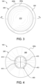
Figure 3 is a top-plan view of the nail ofFigure 1 . -
Figure 4 is a bottom-plan view of the nail ofFigure 1 . -
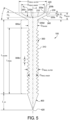
Figure 5 is a cross-sectional-front-elevational view of the nail ofFigure 1 taken substantially along line 5-5 ofFigure 3 . -
Figures 1-5 illustrate oneexample nail 100 of the present disclosure with a head with an inwardly curved top surface. Thenail 100 is sized and shaped to fasten gypsum board or drywall to lumber (though it may be used in any other suitable manner). Thenail 100 has a longitudinal axis A and includes ahead 200, ashank 300 connected to and extending from thehead 200, and atip 400 connected to and extending from theshank 300. - The
head 200 includes a top surface (not labeled) including an inwardlycurved surface 210 and anannular rim surface 220, acylindrical side surface 230, and a radially inwardly taperedannular bottom surface 240. A top portion of thehead 200 includes the top surface (including the inwardlycurved surface 210 and the annular rim surface 220) and thecylindrical side surface 230, and a bottom portion of the head includes the radially inwardly, linearly taperedannular bottom surface 240. As best shown inFigure 5 , thehead 400 has a height HHEAD, which is 1.4-2.0 millimeters in this example embodiment (though it may be any suitable value in other embodiments). The head also has an outer diameter DHEAD, OUTER, which is 7.2-7.5 millimeters in this example embodiment (though it may be any suitable range of values in other embodiments). - The inwardly
curved surface 210 has a trough orbottommost point 200e, and acircular edge 200a defines a periphery of the inwardlycurved surface 210. The inwardlycurved surface 210 is centered on the longitudinal axis A such that the longitudinal axis A intersects the trough or bottom point of the inwardlycurved surface 200e and such that all points along thecircular edge 200a are equidistant from the longitudinal axis. In this example embodiment, the inwardlycurved surface 210 curves inwardly toward thetip 400 and has a radius RC, which is 6.5 millimeters (though it may be any suitable value in other embodiments). The curvature is circumferentially uniform such that the inwardlycurved surface 210 defines a rounded cavity shaped like a partial sphere. Put differently, the inwardlycurved surface 210 is symmetrical about the longitudinal axis A such that the profile the inwardlycurved surface 210 forms when viewed in cross-section is identical for all planes including the longitudinal axis A. Thecircular edge 200a has a diameter DHEAD, INNER, which is equal to 13 millimeters in this example embodiment (though it may be any suitable value in other embodiments). The inwardlycurved surface 210 has a height HC, which is 0.5-1.0 millimeters in this example embodiment (though it may be any suitable range of values in other embodiments). - The
annular rim surface 220 extends from thecircular edge 200a, which defines an inner circular edge of theannular rim surface 220, to acircular edge 200b, which defines an outer circular edge of theannular rim surface 220. Theannular rim surface 220 is integrally connected to the inwardlycurved surface 210 at thecircular edge 200a. Thecircular edge 200b has the diameter DHEAD, OUTER. - In various embodiments the inwardly
curved surface 210 and theannular rim surface 220 are shaped such that a driver blade having an outwardly curved driving tip can engage part of both the inwardlycurved surface 210 and theannular rim surface 220 when driving thenail 100 into a substrate. - The
cylindrical side surface 230 extends from the circular edge 220b, which defines an upper circular edge of thecylindrical side surface 230, to a circular edge 220c, which defines a lower circular edge of thecylindrical side surface 230. Thecylindrical side surface 230 is integrally connected to theannular rim surface 220 at thecircular edge 200b. The circular edge 220c has the diameter DHEAD, OUTER. Thecylindrical side surface 230 has a height HSS, which is 0.09 millimeters in this example embodiment (though it may be any suitable range of values in other embodiments). - The inwardly, linearly tapered
annular bottom surface 240 extends from thecircular edge 200c, which defines an upper circular edge of the inwardly taperedannular bottom surface 240, to acircular edge 200d, which defines a lower circular edge of the inwardly taperedannular bottom surface 240. The inwardly, linearly taperedannular bottom surface 240 is integrally connected to thecylindrical side surface 230 at thecircular edge 200c. The inwardly, lineraly taperedannular bottom surface 240 tapers linearly, radially inwardly and toward the tip over a height HB at an angle α, culminating in thecircular edge 200b, which has a diameter DSHANK. In this example embodiment, the height HB is 1.1 millimeters (though it may be any suitable value in other embodiments), the diameter DSHANK is 2.77-2.80 millimeters (though it may be any suitable range of values in other embodiments), and the angle α is 57 degrees (though it may be any suitable value in other embodiments). - The
shank 300 has a length LSHANK, which is 58.0-60.6 millimeters in this example embodiment (though it may be any suitable range of values in other embodiments). Theshank 300 includes acylindrical shank portion 300a and aring shank portion 300b. - The top end of the
cylindrical shank portion 300a is integrally connected to the lower circular edge of the inwardly, linearly taperedannular bottom surface 240.
Thecylindrical shank portion 300a has the diameter DSHANK. - The top end of the
ring shank portion 300b is integrally connected to the bottom end of thecylindrical shank portion 300a. Thering shank portion 300b includesmultiple rings 310 adjacently arranged along the longitudinal axis A and that each taper radially outwardly from an inner diameter DRING, INNER to an outer diameter DRING, OUTER and back radially inwardly to the inner diameter DI. A distance P separates the outermost points ofadjacent rings 310. In this example embodiment, DRING, OUTER is 2.80 millimeters (though it may be any suitable range of values in other embodiments), DRING, INNER is 2.67 millimeters (though it may be any suitable range of values in other embodiments), and P is 0.90-1.10 millimeters (though it may be any suitable range of values in other embodiments). - The
tip 400 is integrally connected to the bottom end of thering shank portion 300b and has a length LTIP, which is 3.75 millimeters in this example embodiment (though it may be any suitable range of values in other embodiments). Thetip 400 includesmultiple flats 410 that taper radially inwardly to apoint 420. In this example embodiment, thetip 400 is a chisel-point tip, though the tip may be any form of tip in other embodiments. - This
example nail 100 is made of electrogalvanized steel, though it may be made of any other suitable material, such as nongalvanized low-carbon steel. - The
nail 100 is by: (1) clamping a wire rod to form therings 310; then (2) striking one end of the rod to form thehead 200; then (3) cutting the nail to length while forming thepointed tip 400. - The nail of the present disclosure solves the above problems. When the inwardly, linearly tapered annular bottom surface of the nail head contacts the exterior surface of the gypsum board as the nail is driven into the gypsum board, it smoothly draws the outer paper inward along the tapered contour without tearing it. This ensures tear-free nail driving under normal circumstances. This also enables the nail head to be driven below the surface of the gypsum board without tearing the paper, and the inwardly curved top surface provides a cavity into which joint compound can be applied. This results in a smooth finished wall. Additionally, use of the nail to secure the gypsum board to the substrate eliminates forms a more secure attachment when compared to conventional nails, which reduces the likelihood of nail pops, and also eliminates air pockets between the gypsum board and the substrate and the underside of the nail head and the substrate, which also reduces the likelihood of nail pops.
- Various changes and modifications to the above-described embodiments described herein will be apparent to those skilled in the art. Not all of the depicted components described in this disclosure may be required, and some implementations may include additional, different, or fewer components from those expressly described in this disclosure. Also, unless otherwise indicated, any directions referred to herein reflect the orientations of the components shown in the corresponding drawings and do not limit the scope of the present disclosure. This specification is intended to be taken as a whole and interpreted in accordance with the principles of the invention as taught herein and understood by one of ordinary skill in the art.
Claims (13)
- A nail (100) for attaching gypsum board to a substrate, the nail having a longitudinal axis and comprising:a head (200) including a top portion and a bottom portion, the top portion including an inwardly curved surface (210) forming a partially spherical cavity, the bottom portion including an inwardly tapered annular bottom surface (240);a shank (300) integrally connected to and extending from the bottom portion of the head; anda tip (400) integrally connected to and extending from the shank and terminating in a free end,characterized in that the inwardly tapered annular bottom surface is tapered linearly, radially inwardly and toward the tip.
- The nail (100) of claim 1, wherein the inwardly curved surface (210) comprises a circular peripheral edge (200a) and a bottom point (200e).
- The nail (100) of claim 2, wherein the longitudinal axis intersects the bottom point (200e).
- The nail (100) of claim 3, wherein the inwardly curved surface (210) is symmetrical about the longitudinal axis such that all points along the circular peripheral edge (200a) are equidistant from the longitudinal axis.
- The nail (100) of claim 2, wherein the top portion of the head further comprises an annular rim surface (220) integrally connected to the inwardly curved surface (210) at the circular peripheral edge (200a).
- The nail (100) of claim 5, wherein the head (200) further comprises a cylindrical side surface (230) integrally connected to the annular top surface.
- The nail (100) of claim 6, wherein the cylindrical side surface (230) is integrally connected to the bottom surface (240).
- The nail (100) of claim 1, wherein the shank (300) comprises a ring shank portion (300b) comprising multiple rings (310) arranged along the longitudinal axis.
- The nail (100) of claim 8, wherein each ring (310) is centered on the longitudinal axis.
- The nail (100) of claim 8, wherein the shank (300) further comprises a cylindrical shank portion (300a) between the head (200) and the ring shank portion (300b).
- The nail (100) of claim 8, wherein each ring (310) tapers radially outwardly relative to the longitudinal axis.
- The nail (100) of claim 1, wherein the free end is pointed.
- The nail (100) of claim 12, wherein the tip (400) comprises multiple flats (410) that taper to the pointed free end.
Applications Claiming Priority (2)
| Application Number | Priority Date | Filing Date | Title |
|---|---|---|---|
| US15/439,884 US10371189B2 (en) | 2017-02-22 | 2017-02-22 | Nail with a head having an inwardly curved top surface |
| PCT/US2018/012924 WO2018156252A1 (en) | 2017-02-22 | 2018-01-09 | Nail with a head having an inwardly curved top surface |
Publications (2)
| Publication Number | Publication Date |
|---|---|
| EP3586014A1 EP3586014A1 (en) | 2020-01-01 |
| EP3586014B1 true EP3586014B1 (en) | 2025-03-05 |
Family
ID=61800654
Family Applications (1)
| Application Number | Title | Priority Date | Filing Date |
|---|---|---|---|
| EP18713731.0A Active EP3586014B1 (en) | 2017-02-22 | 2018-01-09 | Nail with a head having an inwardly curved top surface |
Country Status (5)
| Country | Link |
|---|---|
| US (2) | US10371189B2 (en) |
| EP (1) | EP3586014B1 (en) |
| AU (1) | AU2017201293B2 (en) |
| CA (1) | CA3053335C (en) |
| WO (1) | WO2018156252A1 (en) |
Families Citing this family (11)
| Publication number | Priority date | Publication date | Assignee | Title |
|---|---|---|---|---|
| USD867865S1 (en) * | 2017-02-22 | 2019-11-26 | Illinois Tool Works Inc. | Nail with a head having an inwardly curved top surface |
| WO2020231917A1 (en) | 2019-05-13 | 2020-11-19 | Enanta Pharmaceuticals, Inc. | Isoxazole derivatives as fxr agonists and methods of use thereof |
| US12146517B2 (en) * | 2020-04-30 | 2024-11-19 | Altenloh, Brinck & Co. Us, Inc. | Self-sealing fastener |
| EP4027026B1 (en) * | 2021-01-07 | 2023-01-25 | Raimund Beck Nageltechnik GmbH | Nail, in particular for use in a nailing apparatus |
| USD985379S1 (en) * | 2021-03-08 | 2023-05-09 | Schrauben Betzer Gmbh & Co Kg | Screw |
| USD986045S1 (en) | 2021-08-31 | 2023-05-16 | Primesource Building Products, Inc. | Fastener |
| US20230061383A1 (en) * | 2021-08-31 | 2023-03-02 | Primesource Building Products, Inc. | Fasteners with increased grip strength |
| USD986728S1 (en) | 2021-08-31 | 2023-05-23 | Primesource Building Products, Inc. | Fastener |
| JP7865012B2 (en) * | 2022-01-13 | 2026-05-26 | マックス株式会社 | Screws |
| US20240271651A1 (en) * | 2023-02-10 | 2024-08-15 | Jeremy Shaw | Drywall Fastening Button Device |
| USD1088854S1 (en) * | 2024-03-22 | 2025-08-19 | David Cowan | Bolt |
Citations (3)
| Publication number | Priority date | Publication date | Assignee | Title |
|---|---|---|---|---|
| US6907699B2 (en) * | 2001-08-03 | 2005-06-21 | Ben L. Schmid | Gypsum wallboard fastener |
| US20110182695A1 (en) * | 2010-01-26 | 2011-07-28 | Christian Beck | Attachment means |
| DE202011052112U1 (en) * | 2011-11-25 | 2012-01-16 | Yeun Chang Hardware Tool Co., Ltd. | Nail with ring-shaped cone part for veneer boards |
Family Cites Families (73)
| Publication number | Priority date | Publication date | Assignee | Title |
|---|---|---|---|---|
| US398260A (en) | 1889-02-19 | Peter v | ||
| US348126A (en) | 1886-08-24 | Wire nail | ||
| US257351A (en) | 1882-05-02 | David ltjbin | ||
| US364439A (en) | 1887-06-07 | Island | ||
| US368687A (en) | 1887-08-23 | Chaeles d | ||
| US410698A (en) * | 1889-09-10 | Island | ||
| US364302A (en) | 1887-06-07 | Charles d | ||
| US1375633A (en) | 1920-09-09 | 1921-04-19 | United Shoe Machinery Corp | Nail |
| US1656333A (en) | 1921-12-27 | 1928-01-17 | United Shoe Machinery Corp | Nail |
| US1428247A (en) | 1922-02-23 | 1922-09-05 | Morris Douglas | Coated nail |
| US1497859A (en) | 1923-06-19 | 1924-06-17 | Allen C Lilly | Nailhead washer |
| US1591810A (en) | 1925-02-10 | 1926-07-06 | L F Grammes & Sons Inc | Clinching nail |
| US1751800A (en) | 1926-07-15 | 1930-03-25 | George E Dickson | Weatherproof nail |
| US1623465A (en) | 1926-07-27 | 1927-04-05 | George A Curtis | Clinching wire nail |
| US1625911A (en) | 1926-10-05 | 1927-04-26 | Harold L Richards | Golf tee |
| US1801077A (en) | 1929-01-18 | 1931-04-14 | Eagle Picher Lead Company | Nail |
| US2086086A (en) * | 1936-03-25 | 1937-07-06 | Lassonde Raoul | Fastener seal |
| US2093610A (en) | 1936-07-13 | 1937-09-21 | Kraemer Sebastian | Nail |
| US2317231A (en) | 1936-09-03 | 1943-04-20 | Seeger Refrigerator Co | Self-embedding nailhead |
| US2126585A (en) | 1936-12-07 | 1938-08-09 | Stone Herman James | Self-locking nail |
| US2353110A (en) | 1940-07-13 | 1944-07-04 | United States Gypsum Co | Plasterboard nail |
| US2558379A (en) * | 1946-08-01 | 1951-06-26 | Res Eng & Mfg | Self-locking fastener |
| US2864276A (en) | 1955-05-05 | 1958-12-16 | Edward M Parker | Deformable head nails |
| US3009382A (en) | 1959-02-16 | 1961-11-21 | Salka Ludovit | Thumbtack having a concave top face |
| US3112667A (en) | 1960-10-03 | 1963-12-03 | Armco Steel Corp | Dry wall nail with a frusto-conical walled head and a serrated shank |
| US3459095A (en) | 1967-09-28 | 1969-08-05 | Omark Industries Inc | Fastening structure |
| US3606344A (en) | 1969-05-28 | 1971-09-20 | Robert J Ball | Set of protective shrouds for golf tees |
| US4011785A (en) | 1971-06-16 | 1977-03-15 | Bliss & Laughlin Ind., Inc. | Nail and powered nailer |
| US3861527A (en) | 1972-12-04 | 1975-01-21 | Spotnails | Package of collated fasteners |
| US3922828A (en) | 1973-11-15 | 1975-12-02 | Tri International Corp | Structural member |
| US3921496A (en) | 1974-11-04 | 1975-11-25 | J Frank Helderman | Fastener assembly |
| US4516780A (en) | 1979-12-11 | 1985-05-14 | Tabet Michael J | Adjustable golf ball tee |
| US4588152A (en) | 1984-03-16 | 1986-05-13 | Illinois Tool Works Inc. | Stucco wall fastener |
| DE3516479A1 (en) * | 1985-05-08 | 1986-11-13 | Rockenfeller KG Befestigungselemente, 5912 Hilchenbach | NAIL WITH A HEAD AT ONE AND A TIP AT THE OTHER END OF THE SHAFT |
| US4687393A (en) | 1985-12-06 | 1987-08-18 | Thompson Wilbur O | Centering pin with ovaloid point |
| US4781508A (en) | 1987-04-13 | 1988-11-01 | Norman Schroeder | Fluted nail |
| US4927309A (en) | 1989-05-08 | 1990-05-22 | Sygnator Henry A | Wire nail |
| US5178503A (en) | 1991-05-02 | 1993-01-12 | Al Losada | Fastener assembly having flat surface for stabilizing the barrel of a power actuated gun |
| CA2099228C (en) | 1992-06-26 | 1996-05-21 | Emanuel Sam Fardell | Fastening nail |
| US5188496A (en) | 1992-07-13 | 1993-02-23 | Giannuzzi Louis | Self-tapping screw-type masonry anchor |
| US5329653A (en) | 1993-01-07 | 1994-07-19 | Harry Hultgren | Carpet restraining strip |
| DE4433918A1 (en) | 1994-04-21 | 1995-10-26 | Fischer Artur Werke Gmbh | Fastening element with expansion element |
| US5709332A (en) | 1994-07-18 | 1998-01-20 | Coop; Jeffrey D. | Nail driving system |
| US5571055A (en) | 1995-03-14 | 1996-11-05 | Lewis; Timothy J. | Golf tee stand with ground anchoring mechanism and non-adjustable base |
| US5810534A (en) * | 1997-02-14 | 1998-09-22 | Senco Products, Inc. | Cleated nail having enlarged diameter shank portion |
| US6789989B2 (en) | 2002-03-13 | 2004-09-14 | Uli Walther | Screw having a head with concave underside |
| USD482086S1 (en) | 2002-09-03 | 2003-11-11 | Thomas A. Metz | Golf tee |
| US20040047713A1 (en) | 2002-09-09 | 2004-03-11 | Jung Young Jae | Screwed nail |
| US7207761B2 (en) * | 2004-07-26 | 2007-04-24 | Illinois Tool Works Inc. | Pin fastener for achieving metal-to-metal connections |
| USD517622S1 (en) | 2005-03-04 | 2006-03-21 | Barouh Eaton Allen Corp. | Golf tee with ball elevating members |
| US7374384B2 (en) | 2005-07-26 | 2008-05-20 | Stanley Fastening Systems, L.P. | Fasteners for securing pallet members together |
| TWM305858U (en) | 2006-07-24 | 2007-02-01 | Samson Power Tool Co Ltd | Nail structure for nail gun |
| US20080175689A1 (en) | 2007-01-22 | 2008-07-24 | Michael Vagedes | Vinyl siding fastener |
| US7819614B2 (en) | 2007-12-14 | 2010-10-26 | Illinois Tool Works, Inc. | Deformed shank fastener |
| USD572323S1 (en) | 2008-01-10 | 2008-07-01 | Michael Joseph Merullo | Golf tee |
| US8740956B2 (en) | 2008-01-10 | 2014-06-03 | J. Scott Smith | Pedicle screw |
| US20090290957A1 (en) | 2008-05-21 | 2009-11-26 | Grace Chance Enterprise Co., Ltd, | Fastener |
| USD601004S1 (en) * | 2008-09-26 | 2009-09-29 | Tyrone Hagins | Head screw |
| USD614942S1 (en) | 2009-04-15 | 2010-05-04 | Power Fasteners, Inc. | Screw |
| USD637071S1 (en) | 2010-01-20 | 2011-05-03 | Powers Fasteners, Inc. | Screw |
| GB201101053D0 (en) | 2011-01-21 | 2011-03-09 | Ollis William H | Fastening arrangements & methods of fixing plaster board panels |
| US20130174629A1 (en) | 2012-01-10 | 2013-07-11 | Chi-hyun KIM | Nail feeding device of nail rolling machine |
| USD733547S1 (en) | 2013-03-15 | 2015-07-07 | Todd Mazur | Color coded, stamped fastener |
| US20150071734A1 (en) | 2013-09-06 | 2015-03-12 | Herman Vallejo | self-wedging concrete nail |
| JPWO2015155803A1 (en) | 2014-04-09 | 2017-04-13 | 種市 薫 | nail |
| WO2015191772A1 (en) | 2014-06-10 | 2015-12-17 | SR Systems, LLC | Enlarged head fastener device and method of manufacture |
| US9962210B2 (en) | 2015-03-24 | 2018-05-08 | Biotronik Ag | Resorbable metal screw with increased torsional strength for osteopathy |
| US10197082B2 (en) | 2015-04-23 | 2019-02-05 | Illinois Tool Works Inc. | Pre-plated spline formed fastener and method for making same |
| US10695994B2 (en) | 2015-11-05 | 2020-06-30 | Guochao Zhu | Quick tire repairing nail and using method thereof |
| US10012256B2 (en) | 2016-04-14 | 2018-07-03 | Simpson Strong-Tie Company, Inc. | Shear wall performance improving fastener |
| USD856788S1 (en) * | 2017-03-31 | 2019-08-20 | Dimex, Llc | Edging spike for lawn and pavers |
| USD843201S1 (en) * | 2017-03-31 | 2019-03-19 | Dimex, Llc | Edging spike for lawn and pavers |
| US20180298577A1 (en) * | 2017-04-12 | 2018-10-18 | Dimex, Llc | Landscape and paver edging spike |
-
2017
- 2017-02-22 US US15/439,884 patent/US10371189B2/en active Active
- 2017-02-24 AU AU2017201293A patent/AU2017201293B2/en active Active
-
2018
- 2018-01-09 CA CA3053335A patent/CA3053335C/en active Active
- 2018-01-09 EP EP18713731.0A patent/EP3586014B1/en active Active
- 2018-01-09 WO PCT/US2018/012924 patent/WO2018156252A1/en not_active Ceased
-
2019
- 2019-06-20 US US16/447,408 patent/US10808742B2/en active Active
Patent Citations (3)
| Publication number | Priority date | Publication date | Assignee | Title |
|---|---|---|---|---|
| US6907699B2 (en) * | 2001-08-03 | 2005-06-21 | Ben L. Schmid | Gypsum wallboard fastener |
| US20110182695A1 (en) * | 2010-01-26 | 2011-07-28 | Christian Beck | Attachment means |
| DE202011052112U1 (en) * | 2011-11-25 | 2012-01-16 | Yeun Chang Hardware Tool Co., Ltd. | Nail with ring-shaped cone part for veneer boards |
Also Published As
| Publication number | Publication date |
|---|---|
| WO2018156252A1 (en) | 2018-08-30 |
| US10808742B2 (en) | 2020-10-20 |
| US20190301511A1 (en) | 2019-10-03 |
| AU2017201293B2 (en) | 2019-01-17 |
| CA3053335A1 (en) | 2018-08-30 |
| US20180238368A1 (en) | 2018-08-23 |
| CA3053335C (en) | 2021-09-21 |
| AU2017201293A1 (en) | 2018-09-06 |
| US10371189B2 (en) | 2019-08-06 |
| EP3586014A1 (en) | 2020-01-01 |
Similar Documents
| Publication | Publication Date | Title |
|---|---|---|
| US10808742B2 (en) | Nail with a head having an inwardly curved top surface | |
| US4003175A (en) | Fastener and roof arrangement using the fastener | |
| US20210205965A1 (en) | Fastener system with stabilizer ribs | |
| US20110100167A1 (en) | Fastener-Driving Sleeve Assembly | |
| US20180163766A1 (en) | Blind bolt fastener with embossments | |
| US6062788A (en) | Nail | |
| JP2002126918A (en) | Hollow shaft tightening device | |
| EP3330552A1 (en) | Structure of screw | |
| US20250369476A1 (en) | Slot geometry | |
| JP2013527903A (en) | fastener | |
| JP2008215464A (en) | Rivet structure and vehicle body structure | |
| US821025A (en) | Nail or screw for securing corrugated iron. | |
| US3112667A (en) | Dry wall nail with a frusto-conical walled head and a serrated shank | |
| WO2016122770A4 (en) | Non-metal and hybrid bottle crowns with opener assembly | |
| US20040013481A1 (en) | Grommet remover tool | |
| WO2020260238A1 (en) | Concrete screw with integrated washer with bulging underhead surface | |
| JP6877798B1 (en) | bolt | |
| EP0672838B1 (en) | Blind rivet assembly | |
| US1975344A (en) | Piston ring | |
| US1738951A (en) | Container | |
| CN210050168U (en) | Open type self-plugging rivet | |
| KR200498601Y1 (en) | Wood screw | |
| US20120224936A1 (en) | Nail anchor | |
| JPWO2018096671A1 (en) | Replacement top lift | |
| JP3179713U (en) | nail |
Legal Events
| Date | Code | Title | Description |
|---|---|---|---|
| STAA | Information on the status of an ep patent application or granted ep patent |
Free format text: STATUS: UNKNOWN |
|
| STAA | Information on the status of an ep patent application or granted ep patent |
Free format text: STATUS: THE INTERNATIONAL PUBLICATION HAS BEEN MADE |
|
| PUAI | Public reference made under article 153(3) epc to a published international application that has entered the european phase |
Free format text: ORIGINAL CODE: 0009012 |
|
| STAA | Information on the status of an ep patent application or granted ep patent |
Free format text: STATUS: REQUEST FOR EXAMINATION WAS MADE |
|
| 17P | Request for examination filed |
Effective date: 20190809 |
|
| AK | Designated contracting states |
Kind code of ref document: A1 Designated state(s): AL AT BE BG CH CY CZ DE DK EE ES FI FR GB GR HR HU IE IS IT LI LT LU LV MC MK MT NL NO PL PT RO RS SE SI SK SM TR |
|
| AX | Request for extension of the european patent |
Extension state: BA ME |
|
| DAV | Request for validation of the european patent (deleted) | ||
| DAX | Request for extension of the european patent (deleted) | ||
| STAA | Information on the status of an ep patent application or granted ep patent |
Free format text: STATUS: EXAMINATION IS IN PROGRESS |
|
| 17Q | First examination report despatched |
Effective date: 20220209 |
|
| GRAP | Despatch of communication of intention to grant a patent |
Free format text: ORIGINAL CODE: EPIDOSNIGR1 |
|
| STAA | Information on the status of an ep patent application or granted ep patent |
Free format text: STATUS: GRANT OF PATENT IS INTENDED |
|
| INTG | Intention to grant announced |
Effective date: 20241016 |
|
| P01 | Opt-out of the competence of the unified patent court (upc) registered |
Free format text: CASE NUMBER: APP_60848/2024 Effective date: 20241112 |
|
| GRAS | Grant fee paid |
Free format text: ORIGINAL CODE: EPIDOSNIGR3 |
|
| GRAA | (expected) grant |
Free format text: ORIGINAL CODE: 0009210 |
|
| STAA | Information on the status of an ep patent application or granted ep patent |
Free format text: STATUS: THE PATENT HAS BEEN GRANTED |
|
| AK | Designated contracting states |
Kind code of ref document: B1 Designated state(s): AL AT BE BG CH CY CZ DE DK EE ES FI FR GB GR HR HU IE IS IT LI LT LU LV MC MK MT NL NO PL PT RO RS SE SI SK SM TR |
|
| REG | Reference to a national code |
Ref country code: GB Ref legal event code: FG4D |
|
| REG | Reference to a national code |
Ref country code: CH Ref legal event code: EP |
|
| REG | Reference to a national code |
Ref country code: DE Ref legal event code: R096 Ref document number: 602018079783 Country of ref document: DE |
|
| REG | Reference to a national code |
Ref country code: IE Ref legal event code: FG4D |
|
| PG25 | Lapsed in a contracting state [announced via postgrant information from national office to epo] |
Ref country code: RS Free format text: LAPSE BECAUSE OF FAILURE TO SUBMIT A TRANSLATION OF THE DESCRIPTION OR TO PAY THE FEE WITHIN THE PRESCRIBED TIME-LIMIT Effective date: 20250605 |
|
| PG25 | Lapsed in a contracting state [announced via postgrant information from national office to epo] |
Ref country code: FI Free format text: LAPSE BECAUSE OF FAILURE TO SUBMIT A TRANSLATION OF THE DESCRIPTION OR TO PAY THE FEE WITHIN THE PRESCRIBED TIME-LIMIT Effective date: 20250305 |
|
| REG | Reference to a national code |
Ref country code: NL Ref legal event code: MP Effective date: 20250305 |
|
| PG25 | Lapsed in a contracting state [announced via postgrant information from national office to epo] |
Ref country code: ES Free format text: LAPSE BECAUSE OF FAILURE TO SUBMIT A TRANSLATION OF THE DESCRIPTION OR TO PAY THE FEE WITHIN THE PRESCRIBED TIME-LIMIT Effective date: 20250305 |
|
| REG | Reference to a national code |
Ref country code: LT Ref legal event code: MG9D |
|
| PG25 | Lapsed in a contracting state [announced via postgrant information from national office to epo] |
Ref country code: NO Free format text: LAPSE BECAUSE OF FAILURE TO SUBMIT A TRANSLATION OF THE DESCRIPTION OR TO PAY THE FEE WITHIN THE PRESCRIBED TIME-LIMIT Effective date: 20250605 |
|
| PG25 | Lapsed in a contracting state [announced via postgrant information from national office to epo] |
Ref country code: HR Free format text: LAPSE BECAUSE OF FAILURE TO SUBMIT A TRANSLATION OF THE DESCRIPTION OR TO PAY THE FEE WITHIN THE PRESCRIBED TIME-LIMIT Effective date: 20250305 |
|
| PG25 | Lapsed in a contracting state [announced via postgrant information from national office to epo] |
Ref country code: LV Free format text: LAPSE BECAUSE OF FAILURE TO SUBMIT A TRANSLATION OF THE DESCRIPTION OR TO PAY THE FEE WITHIN THE PRESCRIBED TIME-LIMIT Effective date: 20250305 |
|
| PG25 | Lapsed in a contracting state [announced via postgrant information from national office to epo] |
Ref country code: GR Free format text: LAPSE BECAUSE OF FAILURE TO SUBMIT A TRANSLATION OF THE DESCRIPTION OR TO PAY THE FEE WITHIN THE PRESCRIBED TIME-LIMIT Effective date: 20250606 Ref country code: BG Free format text: LAPSE BECAUSE OF FAILURE TO SUBMIT A TRANSLATION OF THE DESCRIPTION OR TO PAY THE FEE WITHIN THE PRESCRIBED TIME-LIMIT Effective date: 20250305 |
|
| REG | Reference to a national code |
Ref country code: AT Ref legal event code: MK05 Ref document number: 1773163 Country of ref document: AT Kind code of ref document: T Effective date: 20250305 |
|
| PG25 | Lapsed in a contracting state [announced via postgrant information from national office to epo] |
Ref country code: NL Free format text: LAPSE BECAUSE OF FAILURE TO SUBMIT A TRANSLATION OF THE DESCRIPTION OR TO PAY THE FEE WITHIN THE PRESCRIBED TIME-LIMIT Effective date: 20250305 |
|
| PG25 | Lapsed in a contracting state [announced via postgrant information from national office to epo] |
Ref country code: SE Free format text: LAPSE BECAUSE OF FAILURE TO SUBMIT A TRANSLATION OF THE DESCRIPTION OR TO PAY THE FEE WITHIN THE PRESCRIBED TIME-LIMIT Effective date: 20250305 |
|
| PG25 | Lapsed in a contracting state [announced via postgrant information from national office to epo] |
Ref country code: SM Free format text: LAPSE BECAUSE OF FAILURE TO SUBMIT A TRANSLATION OF THE DESCRIPTION OR TO PAY THE FEE WITHIN THE PRESCRIBED TIME-LIMIT Effective date: 20250305 |
|
| PG25 | Lapsed in a contracting state [announced via postgrant information from national office to epo] |
Ref country code: PT Free format text: LAPSE BECAUSE OF FAILURE TO SUBMIT A TRANSLATION OF THE DESCRIPTION OR TO PAY THE FEE WITHIN THE PRESCRIBED TIME-LIMIT Effective date: 20250707 |
|
| PG25 | Lapsed in a contracting state [announced via postgrant information from national office to epo] |
Ref country code: PL Free format text: LAPSE BECAUSE OF FAILURE TO SUBMIT A TRANSLATION OF THE DESCRIPTION OR TO PAY THE FEE WITHIN THE PRESCRIBED TIME-LIMIT Effective date: 20250305 Ref country code: IT Free format text: LAPSE BECAUSE OF FAILURE TO SUBMIT A TRANSLATION OF THE DESCRIPTION OR TO PAY THE FEE WITHIN THE PRESCRIBED TIME-LIMIT Effective date: 20250305 |
|
| PG25 | Lapsed in a contracting state [announced via postgrant information from national office to epo] |
Ref country code: AT Free format text: LAPSE BECAUSE OF FAILURE TO SUBMIT A TRANSLATION OF THE DESCRIPTION OR TO PAY THE FEE WITHIN THE PRESCRIBED TIME-LIMIT Effective date: 20250305 |
|
| PG25 | Lapsed in a contracting state [announced via postgrant information from national office to epo] |
Ref country code: CZ Free format text: LAPSE BECAUSE OF FAILURE TO SUBMIT A TRANSLATION OF THE DESCRIPTION OR TO PAY THE FEE WITHIN THE PRESCRIBED TIME-LIMIT Effective date: 20250305 Ref country code: EE Free format text: LAPSE BECAUSE OF FAILURE TO SUBMIT A TRANSLATION OF THE DESCRIPTION OR TO PAY THE FEE WITHIN THE PRESCRIBED TIME-LIMIT Effective date: 20250305 |
|
| PG25 | Lapsed in a contracting state [announced via postgrant information from national office to epo] |
Ref country code: RO Free format text: LAPSE BECAUSE OF FAILURE TO SUBMIT A TRANSLATION OF THE DESCRIPTION OR TO PAY THE FEE WITHIN THE PRESCRIBED TIME-LIMIT Effective date: 20250305 |
|
| PG25 | Lapsed in a contracting state [announced via postgrant information from national office to epo] |
Ref country code: SK Free format text: LAPSE BECAUSE OF FAILURE TO SUBMIT A TRANSLATION OF THE DESCRIPTION OR TO PAY THE FEE WITHIN THE PRESCRIBED TIME-LIMIT Effective date: 20250305 |
|
| PG25 | Lapsed in a contracting state [announced via postgrant information from national office to epo] |
Ref country code: IS Free format text: LAPSE BECAUSE OF FAILURE TO SUBMIT A TRANSLATION OF THE DESCRIPTION OR TO PAY THE FEE WITHIN THE PRESCRIBED TIME-LIMIT Effective date: 20250705 |
|
| REG | Reference to a national code |
Ref country code: DE Ref legal event code: R097 Ref document number: 602018079783 Country of ref document: DE |
|
| PLBE | No opposition filed within time limit |
Free format text: ORIGINAL CODE: 0009261 |
|
| STAA | Information on the status of an ep patent application or granted ep patent |
Free format text: STATUS: NO OPPOSITION FILED WITHIN TIME LIMIT |
|
| PG25 | Lapsed in a contracting state [announced via postgrant information from national office to epo] |
Ref country code: DK Free format text: LAPSE BECAUSE OF FAILURE TO SUBMIT A TRANSLATION OF THE DESCRIPTION OR TO PAY THE FEE WITHIN THE PRESCRIBED TIME-LIMIT Effective date: 20250305 |
|
| REG | Reference to a national code |
Ref country code: CH Ref legal event code: L10 Free format text: ST27 STATUS EVENT CODE: U-0-0-L10-L00 (AS PROVIDED BY THE NATIONAL OFFICE) Effective date: 20260114 |
|
| 26N | No opposition filed |
Effective date: 20251208 |
|
| PGFP | Annual fee paid to national office [announced via postgrant information from national office to epo] |
Ref country code: GB Payment date: 20260127 Year of fee payment: 9 |
|
| PGFP | Annual fee paid to national office [announced via postgrant information from national office to epo] |
Ref country code: DE Payment date: 20260128 Year of fee payment: 9 |
|
| PGFP | Annual fee paid to national office [announced via postgrant information from national office to epo] |
Ref country code: FR Payment date: 20260126 Year of fee payment: 9 |
|
| PG25 | Lapsed in a contracting state [announced via postgrant information from national office to epo] |
Ref country code: LT Free format text: LAPSE BECAUSE OF FAILURE TO SUBMIT A TRANSLATION OF THE DESCRIPTION OR TO PAY THE FEE WITHIN THE PRESCRIBED TIME-LIMIT Effective date: 20250305 |