EP3585995B1 - Verwendung von dekompression von naturgas zur verminderung der lufttemperatur eines verbrennungsmotors - Google Patents
Verwendung von dekompression von naturgas zur verminderung der lufttemperatur eines verbrennungsmotors Download PDFInfo
- Publication number
- EP3585995B1 EP3585995B1 EP18708801.8A EP18708801A EP3585995B1 EP 3585995 B1 EP3585995 B1 EP 3585995B1 EP 18708801 A EP18708801 A EP 18708801A EP 3585995 B1 EP3585995 B1 EP 3585995B1
- Authority
- EP
- European Patent Office
- Prior art keywords
- fuel
- air
- internal combustion
- combustion engine
- supply line
- Prior art date
- Legal status (The legal status is an assumption and is not a legal conclusion. Google has not performed a legal analysis and makes no representation as to the accuracy of the status listed.)
- Active
Links
Images

Classifications
-
- F—MECHANICAL ENGINEERING; LIGHTING; HEATING; WEAPONS; BLASTING
- F02—COMBUSTION ENGINES; HOT-GAS OR COMBUSTION-PRODUCT ENGINE PLANTS
- F02M—SUPPLYING COMBUSTION ENGINES IN GENERAL WITH COMBUSTIBLE MIXTURES OR CONSTITUENTS THEREOF
- F02M21/00—Apparatus for supplying engines with non-liquid fuels, e.g. gaseous fuels stored in liquid form
- F02M21/02—Apparatus for supplying engines with non-liquid fuels, e.g. gaseous fuels stored in liquid form for gaseous fuels
- F02M21/0203—Apparatus for supplying engines with non-liquid fuels, e.g. gaseous fuels stored in liquid form for gaseous fuels characterised by the type of gaseous fuel
- F02M21/0215—Mixtures of gaseous fuels; Natural gas; Biogas; Mine gas; Landfill gas
-
- F—MECHANICAL ENGINEERING; LIGHTING; HEATING; WEAPONS; BLASTING
- F02—COMBUSTION ENGINES; HOT-GAS OR COMBUSTION-PRODUCT ENGINE PLANTS
- F02B—INTERNAL-COMBUSTION PISTON ENGINES; COMBUSTION ENGINES IN GENERAL
- F02B29/00—Engines characterised by provision for charging or scavenging not provided for in groups F02B25/00, F02B27/00 or F02B33/00 - F02B39/00; Details thereof
- F02B29/04—Cooling of air intake supply
- F02B29/0406—Layout of the intake air cooling or coolant circuit
-
- F—MECHANICAL ENGINEERING; LIGHTING; HEATING; WEAPONS; BLASTING
- F02—COMBUSTION ENGINES; HOT-GAS OR COMBUSTION-PRODUCT ENGINE PLANTS
- F02B—INTERNAL-COMBUSTION PISTON ENGINES; COMBUSTION ENGINES IN GENERAL
- F02B29/00—Engines characterised by provision for charging or scavenging not provided for in groups F02B25/00, F02B27/00 or F02B33/00 - F02B39/00; Details thereof
- F02B29/04—Cooling of air intake supply
- F02B29/0493—Controlling the air charge temperature
-
- F—MECHANICAL ENGINEERING; LIGHTING; HEATING; WEAPONS; BLASTING
- F02—COMBUSTION ENGINES; HOT-GAS OR COMBUSTION-PRODUCT ENGINE PLANTS
- F02B—INTERNAL-COMBUSTION PISTON ENGINES; COMBUSTION ENGINES IN GENERAL
- F02B43/00—Engines characterised by operating on gaseous fuels; Plants including such engines
-
- F—MECHANICAL ENGINEERING; LIGHTING; HEATING; WEAPONS; BLASTING
- F02—COMBUSTION ENGINES; HOT-GAS OR COMBUSTION-PRODUCT ENGINE PLANTS
- F02D—CONTROLLING COMBUSTION ENGINES
- F02D19/00—Controlling engines characterised by their use of non-liquid fuels, pluralities of fuels, or non-fuel substances added to the combustible mixtures
- F02D19/02—Controlling engines characterised by their use of non-liquid fuels, pluralities of fuels, or non-fuel substances added to the combustible mixtures peculiar to engines working with gaseous fuels
- F02D19/026—Measuring or estimating parameters related to the fuel supply system
- F02D19/027—Determining the fuel pressure, temperature or volume flow, the fuel tank fill level or a valve position
-
- F—MECHANICAL ENGINEERING; LIGHTING; HEATING; WEAPONS; BLASTING
- F02—COMBUSTION ENGINES; HOT-GAS OR COMBUSTION-PRODUCT ENGINE PLANTS
- F02M—SUPPLYING COMBUSTION ENGINES IN GENERAL WITH COMBUSTIBLE MIXTURES OR CONSTITUENTS THEREOF
- F02M21/00—Apparatus for supplying engines with non-liquid fuels, e.g. gaseous fuels stored in liquid form
- F02M21/02—Apparatus for supplying engines with non-liquid fuels, e.g. gaseous fuels stored in liquid form for gaseous fuels
- F02M21/0218—Details on the gaseous fuel supply system, e.g. tanks, valves, pipes, pumps, rails, injectors or mixers
-
- F—MECHANICAL ENGINEERING; LIGHTING; HEATING; WEAPONS; BLASTING
- F02—COMBUSTION ENGINES; HOT-GAS OR COMBUSTION-PRODUCT ENGINE PLANTS
- F02M—SUPPLYING COMBUSTION ENGINES IN GENERAL WITH COMBUSTIBLE MIXTURES OR CONSTITUENTS THEREOF
- F02M21/00—Apparatus for supplying engines with non-liquid fuels, e.g. gaseous fuels stored in liquid form
- F02M21/02—Apparatus for supplying engines with non-liquid fuels, e.g. gaseous fuels stored in liquid form for gaseous fuels
- F02M21/06—Apparatus for de-liquefying, e.g. by heating
-
- F—MECHANICAL ENGINEERING; LIGHTING; HEATING; WEAPONS; BLASTING
- F02—COMBUSTION ENGINES; HOT-GAS OR COMBUSTION-PRODUCT ENGINE PLANTS
- F02D—CONTROLLING COMBUSTION ENGINES
- F02D19/00—Controlling engines characterised by their use of non-liquid fuels, pluralities of fuels, or non-fuel substances added to the combustible mixtures
- F02D19/02—Controlling engines characterised by their use of non-liquid fuels, pluralities of fuels, or non-fuel substances added to the combustible mixtures peculiar to engines working with gaseous fuels
- F02D19/021—Control of components of the fuel supply system
- F02D19/022—Control of components of the fuel supply system to adjust the fuel pressure, temperature or composition
-
- F—MECHANICAL ENGINEERING; LIGHTING; HEATING; WEAPONS; BLASTING
- F02—COMBUSTION ENGINES; HOT-GAS OR COMBUSTION-PRODUCT ENGINE PLANTS
- F02M—SUPPLYING COMBUSTION ENGINES IN GENERAL WITH COMBUSTIBLE MIXTURES OR CONSTITUENTS THEREOF
- F02M21/00—Apparatus for supplying engines with non-liquid fuels, e.g. gaseous fuels stored in liquid form
- F02M21/02—Apparatus for supplying engines with non-liquid fuels, e.g. gaseous fuels stored in liquid form for gaseous fuels
- F02M21/0203—Apparatus for supplying engines with non-liquid fuels, e.g. gaseous fuels stored in liquid form for gaseous fuels characterised by the type of gaseous fuel
- F02M21/0209—Hydrocarbon fuels, e.g. methane or acetylene
- F02M21/0212—Hydrocarbon fuels, e.g. methane or acetylene comprising at least 3 C-Atoms, e.g. liquefied petroleum gas [LPG], propane or butane
-
- F—MECHANICAL ENGINEERING; LIGHTING; HEATING; WEAPONS; BLASTING
- F02—COMBUSTION ENGINES; HOT-GAS OR COMBUSTION-PRODUCT ENGINE PLANTS
- F02M—SUPPLYING COMBUSTION ENGINES IN GENERAL WITH COMBUSTIBLE MIXTURES OR CONSTITUENTS THEREOF
- F02M21/00—Apparatus for supplying engines with non-liquid fuels, e.g. gaseous fuels stored in liquid form
- F02M21/02—Apparatus for supplying engines with non-liquid fuels, e.g. gaseous fuels stored in liquid form for gaseous fuels
- F02M21/0218—Details on the gaseous fuel supply system, e.g. tanks, valves, pipes, pumps, rails, injectors or mixers
- F02M21/023—Valves; Pressure or flow regulators in the fuel supply or return system
- F02M21/0239—Pressure or flow regulators therefor
-
- F—MECHANICAL ENGINEERING; LIGHTING; HEATING; WEAPONS; BLASTING
- F02—COMBUSTION ENGINES; HOT-GAS OR COMBUSTION-PRODUCT ENGINE PLANTS
- F02M—SUPPLYING COMBUSTION ENGINES IN GENERAL WITH COMBUSTIBLE MIXTURES OR CONSTITUENTS THEREOF
- F02M21/00—Apparatus for supplying engines with non-liquid fuels, e.g. gaseous fuels stored in liquid form
- F02M21/02—Apparatus for supplying engines with non-liquid fuels, e.g. gaseous fuels stored in liquid form for gaseous fuels
- F02M21/0218—Details on the gaseous fuel supply system, e.g. tanks, valves, pipes, pumps, rails, injectors or mixers
- F02M21/0245—High pressure fuel supply systems; Rails; Pumps; Arrangement of valves
-
- Y—GENERAL TAGGING OF NEW TECHNOLOGICAL DEVELOPMENTS; GENERAL TAGGING OF CROSS-SECTIONAL TECHNOLOGIES SPANNING OVER SEVERAL SECTIONS OF THE IPC; TECHNICAL SUBJECTS COVERED BY FORMER USPC CROSS-REFERENCE ART COLLECTIONS [XRACs] AND DIGESTS
- Y02—TECHNOLOGIES OR APPLICATIONS FOR MITIGATION OR ADAPTATION AGAINST CLIMATE CHANGE
- Y02T—CLIMATE CHANGE MITIGATION TECHNOLOGIES RELATED TO TRANSPORTATION
- Y02T10/00—Road transport of goods or passengers
- Y02T10/10—Internal combustion engine [ICE] based vehicles
- Y02T10/12—Improving ICE efficiencies
-
- Y—GENERAL TAGGING OF NEW TECHNOLOGICAL DEVELOPMENTS; GENERAL TAGGING OF CROSS-SECTIONAL TECHNOLOGIES SPANNING OVER SEVERAL SECTIONS OF THE IPC; TECHNICAL SUBJECTS COVERED BY FORMER USPC CROSS-REFERENCE ART COLLECTIONS [XRACs] AND DIGESTS
- Y02—TECHNOLOGIES OR APPLICATIONS FOR MITIGATION OR ADAPTATION AGAINST CLIMATE CHANGE
- Y02T—CLIMATE CHANGE MITIGATION TECHNOLOGIES RELATED TO TRANSPORTATION
- Y02T10/00—Road transport of goods or passengers
- Y02T10/10—Internal combustion engine [ICE] based vehicles
- Y02T10/30—Use of alternative fuels, e.g. biofuels
Definitions
- the embodiments herein generally relate to internal combustion engines and more specifically, fuel systems of internal combustion engines fueled by compressed natural gas or liquefied natural gas.
- the natural gas in internal combustion engines that utilize a natural gas engine, the natural gas must be compressed and stored in high pressure containers to be transportable. The compressed natural gas must be then decompressed to be consumed by the internal combustion engine. The natural gas is typically decompressed through a regulator but this decompression process is inefficient and improvements are desired.
- EP 1213461 A2 discloses a method and device for supplying ignitable working gas from cryogenic fuel to an internal combustion engine, which comprises heating of the cryogenic fuel in a fuel tank by a branch of intake air supplied to the combustion engine.
- FR 2517367 A1 discloses a method of operating a motor-compressor group which includes the transfer of latent heat of vaporization of a combustible gas to intake air of a compressor.
- a fuel system comprising: a fuel tank configured to store fuel, a pressure of the fuel within the fuel tank is equal to a first fuel pressure; an internal combustion engine fluidly connected to the fuel tank, the internal combustion engine being configured to consume fuel at a second fuel pressure lower than the first fuel pressure; a fuel regulator fluidly connecting the fuel tank to the internal combustion engine, the fuel regulator being configured to reduce the pressure of the fuel from the first fuel pressure to the second fuel pressure; an air supply assembly configured to supply air from an air inlet to the engine, the air assembly comprising: a first air supply line fluidly connecting the air inlet and the internal combustion engine; a second air supply line fluidly connecting the air inlet and the internal combustion engine, the second air supply line being in parallel with the first air supply line; and an air valve configured to adjust the air flowing through at least one of the first air supply line and the second air supply line; characterized in that the internal combustion engine is located gravitationally above the fuel regulator; and by the first air supply line being in thermal
- the fuel system may include: an air box within the first air supply line interposed between the inlet and the internal combustion engine, the air box containing the fuel regulator, wherein air within the first air supply line is configured to flow across the fuel regulator.
- the fuel system may include: a controller in communication with the air valve and the internal combustion engine, the controller being configured control operation of the air valve in response to air temperature requirements of the internal combustion engine.
- the fuel system may include where the air valve is located in the second air supply line.
- the fuel system may include where the fuel is at least one of compressed natural gas, and liquid natural gas.
- a method of providing fuel to an internal combustion engine comprising: storing fuel within a fuel tank, a pressure of the fuel within the fuel tank is equal to a first fuel pressure; consuming the fuel at a second fuel pressure lower than the first fuel pressure using an internal combustion engine, the internal combustion engine being fluidly connected to the fuel tank; reducing the pressure of the fuel from the first pressure to the second pressure using a fuel regulator, the fuel regulator fluidly connecting the fuel tank to the internal combustion engine; supplying air from an air inlet to the internal combustion engine using an air assembly, the air assembly comprising: a first air supply line fluidly connecting the air inlet and the internal combustion engine; and a second air supply line fluidly connecting the air inlet and the internal combustion engine, the second air supply line being in parallel with the first air supply line; and adjusting the air flowing through at least one of the first air supply line and the second air supply line, using an air valve; characterized in that the internal combustion engine is located gravitationally above the fuel regulator; and by the
- the method may include where the air supply assembly further comprises: an air box within the first air supply line interposed between the inlet and the internal combustion engine, the air box containing the fuel regulator, wherein air within the first air supply line is configured to flow across the fuel regulator.
- the method may include: controlling the operation of the air valve in response to air temperature requirements of the internal combustion engine using a controller in communication with the air valve and the internal combustion engine.
- the method may include where the air valve is located in the second air supply line.
- the method may include where the fuel is at least one of compressed natural gas, and liquid natural gas.
- Technical effects of embodiments of the present disclosure include cooling the air flow into an internal combustion engine using the decompression of fuel flowing into the internal combustion engine.
- Technical effects also include locating the internal combustion engine gravitationally above the fuel regulator.
- FIG. 1 shows a schematic illustration of a fuel system 100 of an internal combustion engine 170.
- the fuel system 100 comprises a fuel tank 150 configured to store fuel 151, an internal combustion engine 170 fluidly connected to the fuel tank 150, a fuel regulator 160 fluidly connecting the fuel tank 150 to the internal combustion engine 170, an air supply assembly 110 configured to supply air 104 from an air inlet 111 to the engine 170, and an air valve 120 configured to adjust the air 104 flowing through the air supply assembly 110.
- the fuel 150 may be compressed natural gas or liquid natural gas such as, for example, propane or butane.
- the fuel pressure of the fuel 151 within the fuel tank 150 is equal to a first fuel pressure P1.
- the internal combustion engine 170 is configured to consume fuel 151 at a second fuel pressure P2 lower than the first fuel pressure P1.
- the fuel regulator 160 is configured to reduce the pressure of the fuel 151 from the first fuel pressure P1 to the second fuel pressure P2.
- the fuel regulator 160 may be a single regulator or a series of regulators.
- the fuel tank 150 is fluidly connected to the fuel regulator 160 through a first fuel line 152 and the fuel regulator 160 is fluidly connected to the engine 170 through a second fuel line 154.
- the internal combustion engine 170 is located gravitationally above the fuel regulator 160.
- positioning the internal combustion engine 170 gravitationally above the fuel regulator 160 allows fuel 151, in the event of a leak when the internal combustion engine 170 is off, to rise up the second fuel line 154 or the air intake line 112 and into the internal combustion engine 170 and be ready to be consumed upon the next start-up of the internal combustion engine 170.
- the engine 170 is running and a leak develops the leaked fuel 151 is transported to the engine 170 via 112 and consumed.
- the leak is excessive then the fuel to air ratio imbalance will cause a warning in the controller 130 and require user intervention.
- the air supply assembly 110 comprises: a first air supply line 112 fluidly connecting the air inlet 111 and the internal combustion engine 170; and a second air supply line 114 fluidly connecting the air inlet 111 and the internal combustion engine 170.
- the first air supply line 112 is in thermal communication with the fuel regulator 160.
- the air supply assembly 110 includes an air box 118.
- the air box 118 is located within the first air supply line 112 interposed between the inlet 111 and the internal combustion engine 170. As seen in FIG. 1 , the air box 118 contains the fuel regulator 160.
- the air 104 within the first air supply line 112 flows through the air box 118, the air 104 flows across the fuel regulator 160, thus allowing thermal communication between the fuel regulator 160 and the air 104 within the air box 118.
- the fuel regulator 160 reduces the pressure of the fuel 151, the temperature of the fuel 151 is reduced in accordance with the Joule-Thompson Effect.
- the cooling of the fuel 151 within the fuel regulator 160 cools the fuel regulator 160 and also cools the air 104 flowing across the fuel regulator 160 within the air box 118.
- the air 104 enters the air inlet 111 at first temperature T1 then flows through the air box 118 and across the fuel regulator 160, which reduces the temperature of the air 104 to a second temperature T2.
- the second temperature T2 is lower than the first temperature T1.
- the air supply assembly 110 includes a second air supply line 114 fluidly connecting the air inlet 111 and the internal combustion engine 170. As seen in FIG. 1 , the second air supply line 114 is in parallel with the first air supply line 112.
- the air supply assembly 110 also includes an air valve 120 configured to adjust the air 104 flowing through at least one of the first air supply line 112 and the second air supply line 114.
- the air valve 120 is located within the second air supply line 114 and adjusts the air 104 flowing through the second air supply line 114 by closing and opening the air valve 120. By adjusting the flow of air 104 through the second air supply line 114, the flow of air 104 through the first air supply line 112 is also adjusted.
- the first air supply line 112 supplies air 104 at a second temperature T2 to the internal combustion engine 170 and the second air supply line 114 supplies air at a first temperature T1 to the internal combustion engine 170.
- the two air supply line 112, 114 combine just prior to entering the internal combustion engine 170 and the air 104 in each air supply line 112, 114 mixes and the temperature of the mixed air 104 is equal to a third temperature T3 when entering the internal combustion engine 170.
- the third temperature T3 is adjusted by controlling the air valve 120 and adjusting the amount of air 104 flowing through each air supply line 112, 114.
- the third temperature T3 will be cooler due to more air 104 arriving at the internal combustion engine 170 having the second temperature T2. Conversely, if more air 104 is forced to flow through the second air supply line 114 then the third temperature T3 will be hotter due to more air 104 arriving at the internal combustion engine 170 having the first temperature T1.
- the fuel system 100 may also include a controller 130 in communication with the air valve 120 and the internal combustion engine 170.
- the controller 130 is configured control operation of the air valve 120 in response to air temperature requirements of the internal combustion engine 170. For example, if the internal combustion engine 170 requires that the air 104 flowing into the internal combustion engine 170 be cooler then the controller 30 will command the air valve 120 to allow more air 104 to flow through the first fuel line 112 and across the fuel regulator 160. In another example, if the internal combustion engine 170 requires that the air 104 flowing into the internal combustion engine 170 be hotter then the controller 30 will command the air valve 120 to allow more air 104 to flow through the second fuel line 114.
- the controller 130 may be an electronic controller including a processor and an associated memory comprising computer-executable instructions that, when executed by the processor, cause the processor to perform various operations.
- the processor may be but is not limited to a single-processor or multi-processor system of any of a wide array of possible architectures, including field programmable gate array (FPGA), central processing unit (CPU), application specific integrated circuits (ASIC), digital signal processor (DSP) or graphics processing unit (GPU) hardware arranged homogenously or heterogeneously.
- the memory may be a storage device such as, for example, a random access memory (RAM), read only memory (ROM), or other electronic, optical, magnetic or any other computer readable medium.
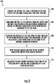
- FIG. 2 shows a flow diagram illustrating a method 200 of providing fuel to an internal combustion engine 170, according to an embodiment of the present disclosure.
- a fuel tank 150 stores fuel 151.
- a pressure of the fuel 151 within the fuel tank 150 is equal to a first fuel pressure P1.
- an internal combustion engine 170 consumes the fuel 151 at a second fuel pressure P2 lower than the first fuel pressure P1.
- the internal combustion engine 170 is fluidly connected to the fuel tank 150.
- the pressure of the fuel 151 is reduced from the first pressure P1 to the second pressure P2 using a fuel regulator 160.
- the fuel regulator 160 fluidly connecting the fuel tank 150 to the internal combustion engine 170.
- air 104 is supplied from an air inlet 111 to the internal combustion engine 170 using an air assembly 110.
- the air assembly 110 comprises: a first air supply line 112 fluidly connecting the air inlet 111 and the internal combustion engine 170.
- the first air supply line 112 is in thermal communication with the fuel regulator 160.
- the first air supply line 112 may be in thermal communication with the fuel regulator 160 through the air box 118.
- the air assembly 110 further comprises: a second air supply line 114 fluidly connecting the air inlet 111 and the internal combustion engine 170.
- the second air supply line 114 is in parallel with the first air supply line 112.
- the air flowing through at least one of the first air supply line 112 and the second air supply line 114 is adjusted using an air valve 120.
- embodiments can be in the form of processor-implemented processes and devices for practicing those processes, such as processor.
- Embodiments can also be in the form of computer program code containing instructions embodied in tangible media, such as floppy diskettes, CD ROMs, hard drives, or any other computer-readable storage medium, wherein, when the computer program code is loaded into and executed by a computer, the computer becomes a device for practicing the embodiments.
- Embodiments can also be in the form of computer program code, for example, whether stored in a storage medium, loaded into and/or executed by a computer, or transmitted over some transmission medium, loaded into and/or executed by a computer, or transmitted over some transmission medium, such as over electrical wiring or cabling, through fiber optics, or via electromagnetic radiation, wherein, when the computer program code is loaded into an executed by a computer, the computer becomes an device for practicing the exemplary embodiments.
- the computer program code segments configure the microprocessor to create specific logic circuits.
Landscapes
- Engineering & Computer Science (AREA)
- Chemical & Material Sciences (AREA)
- Combustion & Propulsion (AREA)
- Mechanical Engineering (AREA)
- General Engineering & Computer Science (AREA)
- Chemical Kinetics & Catalysis (AREA)
- General Chemical & Material Sciences (AREA)
- Oil, Petroleum & Natural Gas (AREA)
- Physics & Mathematics (AREA)
- Thermal Sciences (AREA)
- Output Control And Ontrol Of Special Type Engine (AREA)
- Electrical Control Of Air Or Fuel Supplied To Internal-Combustion Engine (AREA)
Claims (10)
- Kraftstoffsystem (100), umfassend:einen Kraftstofftank (150), der konfiguriert ist, um Kraftstoff (151) zu speichern, wobei ein Druck des Kraftstoffs innerhalb des Kraftstofftanks gleichwertig einem ersten Kraftstoffdruck ist;einen internen Verbrennungsmotor (170), der in Fluidverbindung mit dem internen Kraftstofftank steht, wobei der Verbrennungsmotor konfiguriert ist, um Kraftstoff bei einem zweiten Kraftstoffdruck, der niedriger als der erste Kraftstoffdruck ist, zu verbrauchen;einen Kraftstoffregler (160) der den Kraftstofftank in Fluidverbindung mit dem internen Verbrennungsmotor verbindet, wobei der Kraftstoffregler konfiguriert ist, um den Druck des Kraftstoffs von dem ersten Kraftstoffdruck auf den zweiten Kraftstoffdruck zu reduzieren;eine Luftzufuhrbaugruppe (110), die konfiguriert ist, um Luft (104) von einem Lufteinlass (111) an den Motor zu leiten, wobei die Luftbaugruppe Folgendes umfasst:eine erste Luftzufuhrleitung (112), die in Fluidverbindung den Lufteinlass mit dem internen Verbrennungsmotor verbindet;eine zweite Luftzufuhrleitung (114), die in Fluidverbindung den Lufteinlass mit dem internen Verbrennungsmotor verbindet, wobei die zweite Luftzufuhrleitung parallel zu der ersten Luftzufuhrleitung liegt; undein Entlüftungsventil (120), das konfiguriert ist, um die Luft, die durch mindestens eine der ersten Luftzufuhrleitung und der zweiten Luftzufuhrleitung strömt, einzustellen, dadurch gekennzeichnet, dass:sich der internen Verbrennungsmotor schwerpunktmäßig oberhalb des Kraftstoffreglers befindet; und dassdie erste Luftzufuhrleitung in Thermalkommunikation mit dem Kraftstoffregler steht.
- Kraftstoffsystem (100) nach Anspruch 1, weiter umfassend:
einen Luftkasten (118) innerhalb der ersten Luftzufuhrleitung (112), der zwischen dem Einlass (111) und dem internen Verbrennungsmotor (170) eingefügt ist, wobei der Luftkasten den Kraftstoffregler (160) enthält, wobei Luft (104) innerhalb der ersten Luftzufuhrleitung konfiguriert ist, um über den Kraftstoffregler zu strömen. - Kraftstoffsystem (100) nach Anspruch 1, weiter umfassend:
eine Steuereinheit (130), die in Kommunikation mit dem Entlüftungsventil (120) und dem internen Verbrennungsmotor (170) steht, wobei die Steuereinheit konfiguriert ist, um den Betrieb des Entlüftungsventils als Reaktion auf Lufttemperaturanforderungen des internen Verbrennungsmotors zu steuern. - Kraftstoffsystem (100) nach Anspruch 1, wobei:
sich das Entlüftungsventil (120) in der zweiten Luftzufuhrleitung (114) befindet. - Kraftstoffsystem (100) nach Anspruch 1, wobei:
der Kraftstoff (151) mindestens einer von komprimiertem Erdgas und flüssigem Erdgas ist. - Verfahren (200) zum Bereitstellen von Kraftstoff an einen internen Verbrennungsmotor, wobei das Verfahren Folgendes umfasst:Speichern (204) von Kraftstoff (151) innerhalb eines Kraftstofftanks (150), wobei ein Druck des Kraftstoffs innerhalb des Kraftstofftanks gleichwertig einem ersten Kraftstoffdruck ist;Verbrauchen (206) des Kraftstoffs bei einem zweiten Kraftstoffdruck, der niedriger als der erste Kraftstoffdruck ist, unter Verwendung eines internen Verbrennungsmotors (170), wobei der internen Verbrennungsmotor in Fluidverbindung mit dem Kraftstofftank steht;Reduzieren (208) des Drucks des Kraftstoff von dem ersten Druck auf den zweiten Druck unter Verwendung eines Kraftstoffreglers (160), wobei der Kraftstoffregler in Fluidverbindung den Kraftstofftank mit dem internen Verbrennungsmotor verbindet;Zuführen (210) von Luft (104) von einem Lufteinlass (111) an den internen Verbrennungsmotor unter Verwendung einer Luftbaugruppe (110), wobei die Luftbaugruppe Folgendes umfasst:eine erste Luftzufuhrleitung (112), die in Fluidverbindung den Lufteinlass mit dem internen Verbrennungsmotor verbindet; undeine zweite Luftzufuhrleitung (114), die in Fluidverbindung den Lufteinlass mit dem internen Verbrennungsmotor verbindet, wobei die zweite Luftzufuhrleitung parallel zu der ersten Luftzufuhrleitung liegt; undEinstellen (212) der Luft, die durch mindestens eine der ersten Luftzufuhrleitung und der zweiten Luftzufuhrleitung strömt, unter Verwendung eines Entlüftungsventils (120); dadurch gekennzeichnet, dass:sich der internen Verbrennungsmotor schwerpunktmäßig oberhalb des Kraftstoffreglers befindet; und dassdie erste Luftzufuhrleitung in Thermalkommunikation mit dem Kraftstoffregler steht.
- Verfahren nach Anspruch 6, wobei die Luftzufuhrbaugruppe (110) weiter Folgendes umfasst:
einen Luftkasten (118) innerhalb der ersten Luftzufuhrleitung (112), der zwischen dem Einlass (111) und dem internen Verbrennungsmotor (170) eingefügt ist, wobei der Luftkasten den Kraftstoffregler (160) enthält, wobei Luft (104) innerhalb der ersten Luftzufuhrleitung konfiguriert ist, um über den Kraftstoffregler zu strömen. - Verfahren nach Anspruch 6, weiter umfassend:
Steuern des Betriebs des Entlüftungsventils (120) als Reaktion auf Lufttemperaturanforderungen des internen Verbrennungsmotors (170) unter Verwendung einer Steuereinheit (130), die in Kommunikation mit dem Entlüftungsventil und dem internen Verbrennungsmotor steht. - Verfahren nach Anspruch 6, wobei:
sich das Entlüftungsventil (120) in der zweiten Luftzufuhrleitung (114) befindet. - Verfahren nach Anspruch 6, wobei:
der Kraftstoff (151) mindestens einer von komprimiertem Erdgas und flüssigem Erdgas ist.
Applications Claiming Priority (2)
| Application Number | Priority Date | Filing Date | Title |
|---|---|---|---|
| US201762462469P | 2017-02-23 | 2017-02-23 | |
| PCT/US2018/018657 WO2018156466A1 (en) | 2017-02-23 | 2018-02-20 | Use of decompressing natural gas to lower the intake air temperature of an internal combustion engine |
Publications (2)
| Publication Number | Publication Date |
|---|---|
| EP3585995A1 EP3585995A1 (de) | 2020-01-01 |
| EP3585995B1 true EP3585995B1 (de) | 2022-05-25 |
Family
ID=61563481
Family Applications (1)
| Application Number | Title | Priority Date | Filing Date |
|---|---|---|---|
| EP18708801.8A Active EP3585995B1 (de) | 2017-02-23 | 2018-02-20 | Verwendung von dekompression von naturgas zur verminderung der lufttemperatur eines verbrennungsmotors |
Country Status (4)
| Country | Link |
|---|---|
| US (1) | US10975806B2 (de) |
| EP (1) | EP3585995B1 (de) |
| CN (1) | CN110300844B (de) |
| WO (1) | WO2018156466A1 (de) |
Family Cites Families (13)
| Publication number | Priority date | Publication date | Assignee | Title |
|---|---|---|---|---|
| CA1192973A (en) * | 1981-05-01 | 1985-09-03 | Colin G. Young | Gaseous fuel carburetion |
| FR2517367A1 (fr) * | 1981-11-27 | 1983-06-03 | Roger Claude | Procede et dispositif pour ameliorer le rendement d'un groupe moto-compresseur |
| FR2517397A1 (fr) * | 1981-11-30 | 1983-06-03 | Dba | Frein a tambour a couple regule |
| CA1326794C (en) * | 1989-09-29 | 1994-02-08 | Ortech Corporation | Flow control system |
| DE10060789A1 (de) * | 2000-12-07 | 2002-06-13 | Bayerische Motoren Werke Ag | Verfahren und Anordnung zur Bereitstellung eines zündfähigen Arbeitsgases aus einem Kryo-Kraftstoff |
| WO2002090750A1 (en) * | 2001-05-03 | 2002-11-14 | Was Diesel Now Gas Pty Ltd | Fuel delivery system |
| US6880535B2 (en) * | 2003-03-04 | 2005-04-19 | Chapeau, Inc. | Carburetion for natural gas fueled internal combustion engine using recycled exhaust gas |
| US6932052B1 (en) * | 2004-09-24 | 2005-08-23 | Woodward Governor Company | Air/fuel ratio control system for gaseous fueled engines |
| GB0501335D0 (en) * | 2005-01-21 | 2005-03-02 | Cryostar France Sa | Natural gas supply method and apparatus |
| US7841322B2 (en) * | 2007-11-16 | 2010-11-30 | Dynamic Fuel Systems, Inc. | Super cooled air and fuel induction system for internal combustion engines |
| US7997076B2 (en) * | 2008-03-31 | 2011-08-16 | Cummins, Inc. | Rankine cycle load limiting through use of a recuperator bypass |
| CA2833619C (en) * | 2013-11-21 | 2020-06-30 | Westport Power Inc. | Method and system for delivering a gaseous fuel into the air intake system of an internal combustion engine |
| CN205532847U (zh) * | 2016-05-04 | 2016-08-31 | 北京福田康明斯发动机有限公司 | 天然气发动机系统和车辆 |
-
2018
- 2018-02-20 WO PCT/US2018/018657 patent/WO2018156466A1/en not_active Ceased
- 2018-02-20 CN CN201880013731.6A patent/CN110300844B/zh active Active
- 2018-02-20 US US16/487,901 patent/US10975806B2/en active Active
- 2018-02-20 EP EP18708801.8A patent/EP3585995B1/de active Active
Also Published As
| Publication number | Publication date |
|---|---|
| WO2018156466A1 (en) | 2018-08-30 |
| US10975806B2 (en) | 2021-04-13 |
| US20200232420A1 (en) | 2020-07-23 |
| CN110300844A (zh) | 2019-10-01 |
| EP3585995A1 (de) | 2020-01-01 |
| CN110300844B (zh) | 2021-11-05 |
Similar Documents
| Publication | Publication Date | Title |
|---|---|---|
| US10961109B2 (en) | Fluid bypass method and system for controlling the temperature of a non-petroleum fuel | |
| US9771886B2 (en) | Method and system for delivering a gaseous fuel into the air intake system of an internal combustion engine | |
| US9897055B2 (en) | Method and system for delivering a gaseous fuel into the air intake system of an internal combustion engine | |
| CN112512917B (zh) | 用于向船舶供应燃料的系统和方法 | |
| KR101319364B1 (ko) | 연료용 lng를 이용한 액화가스탱크 압력 조절장치 및 이를 가지는 액화가스운반선 | |
| KR101826687B1 (ko) | 액화가스 운반선의 탱크 운용 시스템 및 방법 | |
| DK2815168T3 (en) | A device for the supply of gas | |
| CN105531526A (zh) | 液态天然气动态冷却 | |
| KR101408357B1 (ko) | Lng를 이용한 액화가스 재액화장치 및 이를 가지는 액화가스운반선 | |
| JP2021516749A (ja) | ガス供給アセンブリ | |
| US10975806B2 (en) | Use of decompressing natural gas to lower the intake air temperature of an internal combustion engine | |
| KR20190041859A (ko) | Lng연료를 이용한 액화가스 재액화장치 및 이를 가지는 액화가스운반선 | |
| US10415509B2 (en) | Cooling system for cryogenic fuel delivery components | |
| KR101435390B1 (ko) | 연료 전지 시스템 및 이를 구비한 선박 | |
| KR20160008808A (ko) | 선박용 엔진의 가스 연료 공급 제어 시스템 및 방법 | |
| KR102389088B1 (ko) | 차량용 가스 연료 공급 장치 | |
| KR20170073077A (ko) | 액화천연가스 재기화 방법 및 시스템 | |
| JP6959805B2 (ja) | 船舶 | |
| US12078128B2 (en) | System and method for supplying fuel for ship | |
| KR102433265B1 (ko) | 가스 처리 시스템 및 이를 포함하는 해양 부유물 | |
| KR20190123452A (ko) | 가스 처리 시스템 및 이를 포함하는 해양 부유물 | |
| KR20170048053A (ko) | Lng 선박의 압축가스탱크 저장 시스템 | |
| KR20260009919A (ko) | 비등 가스를 재응축하기 위한 재응축 시스템 및 관련 방법 | |
| JP2006258118A (ja) | ボイルオフガス吸い込み管冷却システム及びリターンガス供給系統冷却システム | |
| JP2011102635A (ja) | 液化ガス充填装置 |
Legal Events
| Date | Code | Title | Description |
|---|---|---|---|
| STAA | Information on the status of an ep patent application or granted ep patent |
Free format text: STATUS: UNKNOWN |
|
| STAA | Information on the status of an ep patent application or granted ep patent |
Free format text: STATUS: THE INTERNATIONAL PUBLICATION HAS BEEN MADE |
|
| PUAI | Public reference made under article 153(3) epc to a published international application that has entered the european phase |
Free format text: ORIGINAL CODE: 0009012 |
|
| STAA | Information on the status of an ep patent application or granted ep patent |
Free format text: STATUS: REQUEST FOR EXAMINATION WAS MADE |
|
| 17P | Request for examination filed |
Effective date: 20190822 |
|
| AK | Designated contracting states |
Kind code of ref document: A1 Designated state(s): AL AT BE BG CH CY CZ DE DK EE ES FI FR GB GR HR HU IE IS IT LI LT LU LV MC MK MT NL NO PL PT RO RS SE SI SK SM TR |
|
| AX | Request for extension of the european patent |
Extension state: BA ME |
|
| DAV | Request for validation of the european patent (deleted) | ||
| DAX | Request for extension of the european patent (deleted) | ||
| GRAP | Despatch of communication of intention to grant a patent |
Free format text: ORIGINAL CODE: EPIDOSNIGR1 |
|
| STAA | Information on the status of an ep patent application or granted ep patent |
Free format text: STATUS: GRANT OF PATENT IS INTENDED |
|
| GRAS | Grant fee paid |
Free format text: ORIGINAL CODE: EPIDOSNIGR3 |
|
| INTG | Intention to grant announced |
Effective date: 20220309 |
|
| GRAA | (expected) grant |
Free format text: ORIGINAL CODE: 0009210 |
|
| STAA | Information on the status of an ep patent application or granted ep patent |
Free format text: STATUS: THE PATENT HAS BEEN GRANTED |
|
| AK | Designated contracting states |
Kind code of ref document: B1 Designated state(s): AL AT BE BG CH CY CZ DE DK EE ES FI FR GB GR HR HU IE IS IT LI LT LU LV MC MK MT NL NO PL PT RO RS SE SI SK SM TR |
|
| REG | Reference to a national code |
Ref country code: GB Ref legal event code: FG4D |
|
| REG | Reference to a national code |
Ref country code: CH Ref legal event code: EP |
|
| REG | Reference to a national code |
Ref country code: DE Ref legal event code: R096 Ref document number: 602018035957 Country of ref document: DE |
|
| REG | Reference to a national code |
Ref country code: AT Ref legal event code: REF Ref document number: 1494350 Country of ref document: AT Kind code of ref document: T Effective date: 20220615 |
|
| REG | Reference to a national code |
Ref country code: IE Ref legal event code: FG4D |
|
| REG | Reference to a national code |
Ref country code: NL Ref legal event code: FP |
|
| REG | Reference to a national code |
Ref country code: LT Ref legal event code: MG9D |
|
| REG | Reference to a national code |
Ref country code: AT Ref legal event code: MK05 Ref document number: 1494350 Country of ref document: AT Kind code of ref document: T Effective date: 20220525 |
|
| PG25 | Lapsed in a contracting state [announced via postgrant information from national office to epo] |
Ref country code: SE Free format text: LAPSE BECAUSE OF FAILURE TO SUBMIT A TRANSLATION OF THE DESCRIPTION OR TO PAY THE FEE WITHIN THE PRESCRIBED TIME-LIMIT Effective date: 20220525 Ref country code: PT Free format text: LAPSE BECAUSE OF FAILURE TO SUBMIT A TRANSLATION OF THE DESCRIPTION OR TO PAY THE FEE WITHIN THE PRESCRIBED TIME-LIMIT Effective date: 20220926 Ref country code: NO Free format text: LAPSE BECAUSE OF FAILURE TO SUBMIT A TRANSLATION OF THE DESCRIPTION OR TO PAY THE FEE WITHIN THE PRESCRIBED TIME-LIMIT Effective date: 20220825 Ref country code: LT Free format text: LAPSE BECAUSE OF FAILURE TO SUBMIT A TRANSLATION OF THE DESCRIPTION OR TO PAY THE FEE WITHIN THE PRESCRIBED TIME-LIMIT Effective date: 20220525 Ref country code: HR Free format text: LAPSE BECAUSE OF FAILURE TO SUBMIT A TRANSLATION OF THE DESCRIPTION OR TO PAY THE FEE WITHIN THE PRESCRIBED TIME-LIMIT Effective date: 20220525 Ref country code: GR Free format text: LAPSE BECAUSE OF FAILURE TO SUBMIT A TRANSLATION OF THE DESCRIPTION OR TO PAY THE FEE WITHIN THE PRESCRIBED TIME-LIMIT Effective date: 20220826 Ref country code: FI Free format text: LAPSE BECAUSE OF FAILURE TO SUBMIT A TRANSLATION OF THE DESCRIPTION OR TO PAY THE FEE WITHIN THE PRESCRIBED TIME-LIMIT Effective date: 20220525 Ref country code: ES Free format text: LAPSE BECAUSE OF FAILURE TO SUBMIT A TRANSLATION OF THE DESCRIPTION OR TO PAY THE FEE WITHIN THE PRESCRIBED TIME-LIMIT Effective date: 20220525 Ref country code: BG Free format text: LAPSE BECAUSE OF FAILURE TO SUBMIT A TRANSLATION OF THE DESCRIPTION OR TO PAY THE FEE WITHIN THE PRESCRIBED TIME-LIMIT Effective date: 20220825 Ref country code: AT Free format text: LAPSE BECAUSE OF FAILURE TO SUBMIT A TRANSLATION OF THE DESCRIPTION OR TO PAY THE FEE WITHIN THE PRESCRIBED TIME-LIMIT Effective date: 20220525 |
|
| PG25 | Lapsed in a contracting state [announced via postgrant information from national office to epo] |
Ref country code: RS Free format text: LAPSE BECAUSE OF FAILURE TO SUBMIT A TRANSLATION OF THE DESCRIPTION OR TO PAY THE FEE WITHIN THE PRESCRIBED TIME-LIMIT Effective date: 20220525 Ref country code: PL Free format text: LAPSE BECAUSE OF FAILURE TO SUBMIT A TRANSLATION OF THE DESCRIPTION OR TO PAY THE FEE WITHIN THE PRESCRIBED TIME-LIMIT Effective date: 20220525 Ref country code: LV Free format text: LAPSE BECAUSE OF FAILURE TO SUBMIT A TRANSLATION OF THE DESCRIPTION OR TO PAY THE FEE WITHIN THE PRESCRIBED TIME-LIMIT Effective date: 20220525 Ref country code: IS Free format text: LAPSE BECAUSE OF FAILURE TO SUBMIT A TRANSLATION OF THE DESCRIPTION OR TO PAY THE FEE WITHIN THE PRESCRIBED TIME-LIMIT Effective date: 20220925 |
|
| PG25 | Lapsed in a contracting state [announced via postgrant information from national office to epo] |
Ref country code: SM Free format text: LAPSE BECAUSE OF FAILURE TO SUBMIT A TRANSLATION OF THE DESCRIPTION OR TO PAY THE FEE WITHIN THE PRESCRIBED TIME-LIMIT Effective date: 20220525 Ref country code: SK Free format text: LAPSE BECAUSE OF FAILURE TO SUBMIT A TRANSLATION OF THE DESCRIPTION OR TO PAY THE FEE WITHIN THE PRESCRIBED TIME-LIMIT Effective date: 20220525 Ref country code: RO Free format text: LAPSE BECAUSE OF FAILURE TO SUBMIT A TRANSLATION OF THE DESCRIPTION OR TO PAY THE FEE WITHIN THE PRESCRIBED TIME-LIMIT Effective date: 20220525 Ref country code: EE Free format text: LAPSE BECAUSE OF FAILURE TO SUBMIT A TRANSLATION OF THE DESCRIPTION OR TO PAY THE FEE WITHIN THE PRESCRIBED TIME-LIMIT Effective date: 20220525 Ref country code: DK Free format text: LAPSE BECAUSE OF FAILURE TO SUBMIT A TRANSLATION OF THE DESCRIPTION OR TO PAY THE FEE WITHIN THE PRESCRIBED TIME-LIMIT Effective date: 20220525 Ref country code: CZ Free format text: LAPSE BECAUSE OF FAILURE TO SUBMIT A TRANSLATION OF THE DESCRIPTION OR TO PAY THE FEE WITHIN THE PRESCRIBED TIME-LIMIT Effective date: 20220525 |
|
| REG | Reference to a national code |
Ref country code: DE Ref legal event code: R097 Ref document number: 602018035957 Country of ref document: DE |
|
| PG25 | Lapsed in a contracting state [announced via postgrant information from national office to epo] |
Ref country code: AL Free format text: LAPSE BECAUSE OF FAILURE TO SUBMIT A TRANSLATION OF THE DESCRIPTION OR TO PAY THE FEE WITHIN THE PRESCRIBED TIME-LIMIT Effective date: 20220525 |
|
| PLBE | No opposition filed within time limit |
Free format text: ORIGINAL CODE: 0009261 |
|
| STAA | Information on the status of an ep patent application or granted ep patent |
Free format text: STATUS: NO OPPOSITION FILED WITHIN TIME LIMIT |
|
| 26N | No opposition filed |
Effective date: 20230228 |
|
| PG25 | Lapsed in a contracting state [announced via postgrant information from national office to epo] |
Ref country code: SI Free format text: LAPSE BECAUSE OF FAILURE TO SUBMIT A TRANSLATION OF THE DESCRIPTION OR TO PAY THE FEE WITHIN THE PRESCRIBED TIME-LIMIT Effective date: 20220525 |
|
| PG25 | Lapsed in a contracting state [announced via postgrant information from national office to epo] |
Ref country code: MC Free format text: LAPSE BECAUSE OF FAILURE TO SUBMIT A TRANSLATION OF THE DESCRIPTION OR TO PAY THE FEE WITHIN THE PRESCRIBED TIME-LIMIT Effective date: 20220525 |
|
| REG | Reference to a national code |
Ref country code: CH Ref legal event code: PL |
|
| REG | Reference to a national code |
Ref country code: BE Ref legal event code: MM Effective date: 20230228 |
|
| PG25 | Lapsed in a contracting state [announced via postgrant information from national office to epo] |
Ref country code: LU Free format text: LAPSE BECAUSE OF NON-PAYMENT OF DUE FEES Effective date: 20230220 Ref country code: LI Free format text: LAPSE BECAUSE OF NON-PAYMENT OF DUE FEES Effective date: 20230228 Ref country code: CH Free format text: LAPSE BECAUSE OF NON-PAYMENT OF DUE FEES Effective date: 20230228 |
|
| REG | Reference to a national code |
Ref country code: IE Ref legal event code: MM4A |
|
| PG25 | Lapsed in a contracting state [announced via postgrant information from national office to epo] |
Ref country code: IT Free format text: LAPSE BECAUSE OF FAILURE TO SUBMIT A TRANSLATION OF THE DESCRIPTION OR TO PAY THE FEE WITHIN THE PRESCRIBED TIME-LIMIT Effective date: 20220525 Ref country code: IE Free format text: LAPSE BECAUSE OF NON-PAYMENT OF DUE FEES Effective date: 20230220 |
|
| PG25 | Lapsed in a contracting state [announced via postgrant information from national office to epo] |
Ref country code: BE Free format text: LAPSE BECAUSE OF NON-PAYMENT OF DUE FEES Effective date: 20230228 |
|
| PG25 | Lapsed in a contracting state [announced via postgrant information from national office to epo] |
Ref country code: BG Free format text: LAPSE BECAUSE OF FAILURE TO SUBMIT A TRANSLATION OF THE DESCRIPTION OR TO PAY THE FEE WITHIN THE PRESCRIBED TIME-LIMIT Effective date: 20220525 |
|
| PG25 | Lapsed in a contracting state [announced via postgrant information from national office to epo] |
Ref country code: BG Free format text: LAPSE BECAUSE OF FAILURE TO SUBMIT A TRANSLATION OF THE DESCRIPTION OR TO PAY THE FEE WITHIN THE PRESCRIBED TIME-LIMIT Effective date: 20220525 |
|
| PGFP | Annual fee paid to national office [announced via postgrant information from national office to epo] |
Ref country code: NL Payment date: 20250121 Year of fee payment: 8 |
|
| PGFP | Annual fee paid to national office [announced via postgrant information from national office to epo] |
Ref country code: DE Payment date: 20250122 Year of fee payment: 8 |
|
| PGFP | Annual fee paid to national office [announced via postgrant information from national office to epo] |
Ref country code: FR Payment date: 20250122 Year of fee payment: 8 |
|
| PGFP | Annual fee paid to national office [announced via postgrant information from national office to epo] |
Ref country code: GB Payment date: 20250123 Year of fee payment: 8 |
|
| PG25 | Lapsed in a contracting state [announced via postgrant information from national office to epo] |
Ref country code: CY Free format text: LAPSE BECAUSE OF FAILURE TO SUBMIT A TRANSLATION OF THE DESCRIPTION OR TO PAY THE FEE WITHIN THE PRESCRIBED TIME-LIMIT; INVALID AB INITIO Effective date: 20180220 |
|
| PG25 | Lapsed in a contracting state [announced via postgrant information from national office to epo] |
Ref country code: HU Free format text: LAPSE BECAUSE OF FAILURE TO SUBMIT A TRANSLATION OF THE DESCRIPTION OR TO PAY THE FEE WITHIN THE PRESCRIBED TIME-LIMIT; INVALID AB INITIO Effective date: 20180220 |
|
| PG25 | Lapsed in a contracting state [announced via postgrant information from national office to epo] |
Ref country code: TR Free format text: LAPSE BECAUSE OF FAILURE TO SUBMIT A TRANSLATION OF THE DESCRIPTION OR TO PAY THE FEE WITHIN THE PRESCRIBED TIME-LIMIT Effective date: 20220525 |