EP3585708B1 - Capsule for infusion and soluble beverages with anti-drip system - Google Patents
Capsule for infusion and soluble beverages with anti-drip system Download PDFInfo
- Publication number
- EP3585708B1 EP3585708B1 EP18712456.5A EP18712456A EP3585708B1 EP 3585708 B1 EP3585708 B1 EP 3585708B1 EP 18712456 A EP18712456 A EP 18712456A EP 3585708 B1 EP3585708 B1 EP 3585708B1
- Authority
- EP
- European Patent Office
- Prior art keywords
- capsule
- labyrinth
- capillary channel
- base
- capillary
- Prior art date
- Legal status (The legal status is an assumption and is not a legal conclusion. Google has not performed a legal analysis and makes no representation as to the accuracy of the status listed.)
- Active
Links
- 239000002775 capsule Substances 0.000 title claims description 60
- 235000013361 beverage Nutrition 0.000 title claims description 31
- 238000001802 infusion Methods 0.000 title claims description 5
- 239000012530 fluid Substances 0.000 claims description 11
- 239000000126 substance Substances 0.000 claims description 8
- 238000007789 sealing Methods 0.000 claims description 6
- 238000004804 winding Methods 0.000 claims description 2
- 238000002360 preparation method Methods 0.000 description 18
- 235000016213 coffee Nutrition 0.000 description 5
- 235000013353 coffee beverage Nutrition 0.000 description 5
- 241001122767 Theaceae Species 0.000 description 4
- 235000013616 tea Nutrition 0.000 description 4
- 235000019219 chocolate Nutrition 0.000 description 3
- 230000000694 effects Effects 0.000 description 3
- 235000015092 herbal tea Nutrition 0.000 description 3
- 235000013336 milk Nutrition 0.000 description 3
- 239000008267 milk Substances 0.000 description 3
- 210000004080 milk Anatomy 0.000 description 3
- 239000000843 powder Substances 0.000 description 3
- XLYOFNOQVPJJNP-UHFFFAOYSA-N water Substances O XLYOFNOQVPJJNP-UHFFFAOYSA-N 0.000 description 3
- XAGFODPZIPBFFR-UHFFFAOYSA-N aluminium Chemical compound [Al] XAGFODPZIPBFFR-UHFFFAOYSA-N 0.000 description 2
- 229910052782 aluminium Inorganic materials 0.000 description 2
- 239000008187 granular material Substances 0.000 description 2
- 238000002347 injection Methods 0.000 description 2
- 239000007924 injection Substances 0.000 description 2
- 238000004806 packaging method and process Methods 0.000 description 2
- 239000000243 solution Substances 0.000 description 2
- 238000003466 welding Methods 0.000 description 2
- 238000004026 adhesive bonding Methods 0.000 description 1
- 239000002131 composite material Substances 0.000 description 1
- 230000001419 dependent effect Effects 0.000 description 1
- 238000001746 injection moulding Methods 0.000 description 1
- 235000021539 instant coffee Nutrition 0.000 description 1
- 239000007788 liquid Substances 0.000 description 1
- 239000000463 material Substances 0.000 description 1
- 230000035515 penetration Effects 0.000 description 1
- 238000000926 separation method Methods 0.000 description 1
- 239000002356 single layer Substances 0.000 description 1
Images


Classifications
-
- B—PERFORMING OPERATIONS; TRANSPORTING
- B65—CONVEYING; PACKING; STORING; HANDLING THIN OR FILAMENTARY MATERIAL
- B65D—CONTAINERS FOR STORAGE OR TRANSPORT OF ARTICLES OR MATERIALS, e.g. BAGS, BARRELS, BOTTLES, BOXES, CANS, CARTONS, CRATES, DRUMS, JARS, TANKS, HOPPERS, FORWARDING CONTAINERS; ACCESSORIES, CLOSURES, OR FITTINGS THEREFOR; PACKAGING ELEMENTS; PACKAGES
- B65D85/00—Containers, packaging elements or packages, specially adapted for particular articles or materials
- B65D85/70—Containers, packaging elements or packages, specially adapted for particular articles or materials for materials not otherwise provided for
- B65D85/804—Disposable containers or packages with contents which are mixed, infused or dissolved in situ, i.e. without having been previously removed from the package
- B65D85/8043—Packages adapted to allow liquid to pass through the contents
- B65D85/8055—Means for influencing the liquid flow inside the package
Definitions
- the object of the present invention is a capsule for the preparation of infused or soluble beverages.
- the object of the present invention is a capsule for the packaging of concentrated products (for example in the form of powder, granules, leaves) in predetermined and single-use doses for the impromptu preparation of beverages (such as tea, coffee, herbal teas, milk, chocolate, etc.) by introducing a fluid under pressure (usually hot water) into the same capsule.
- concentrated products for example in the form of powder, granules, leaves
- beverages such as tea, coffee, herbal teas, milk, chocolate, etc.
- Such known capsules like for example those described in WO2016/ 193961 A2 , contain a pre-packaged single-use dose of the substance to be infused, enclosed within a plastic container (called a cup), closed by a cover.
- a plastic container called a cup
- the object of the present invention is to provide a capsule for the preparation of infused or soluble beverages that solves the problems of the known art by taking into account the needs of the sector.
- the object of the present invention is to provide a capsule for the preparation of infused beverages equipped with an anti-drip system which, by exploiting the principle of capillarity, prevents the fluids remaining inside the cup from leaking out, once the capsule is disengaged from the infuser group of the preparation machine.
- a capsule for the preparation of infused or soluble beverages is shown, indicated at the reference number 1.
- Capsule 1 comprises a body or cup 2 suitable for defining an internal volume V for containing at least one substance 11 to be infused or dissolved, typically in powder or granular form.
- the cup 2 is made of plastic material, preferably by injection or co-injection molding, or thermoformed.
- the cup 2 is provided, on the one side, with a bottom 3 and, on the opposite side, with an inlet opening 21 defined by an edge 4 protruding outward.
- the capsule 1 comprises a cover 6 fixed by bonding or welding to the upper edge 4 adapted to seal the cup 2 at the top.
- the cup 2 is provided externally on the bottom 3 with an outlet opening 31, defined by a nozzle 32, adapted to allow the outflow of the infused beverage.
- the cup 2 is provided internally at the bottom 3 with an inner base 33 provided with a plurality of reliefs 310, 320, 360 projecting vertically with respect to the same base 33.
- the reliefs protrude toward the inside of the cup 2, toward the cover 6.
- the top surface of the reliefs 310, 320, 360 is substantially flat and devoid of cutting, puncture or tearing elements.
- the base 33 comprises a central portion 310 defined by a first relief covering the outlet opening 31 of the nozzle 32.
- the central portion 310 is provided with at least one connection opening 311 between the inside of the cup 2 and the outlet opening 31 to allow the flow of the infused beverage out of the capsule 1.
- the central portion 310 comprises a plurality of connection openings 311.
- the base 33 comprises a labyrinth 30 adapted to prevent, by capillarity, the passage of the infused beverage towards the nozzle 32 when the pressure inside the capsule 1 drops below a threshold value or ceases altogether when the capsule 1 is disengaged from the infuser group of the machine.
- the labyrinth 30 is defined by a plurality of reliefs called labyrinth portions 320.
- the base 33 comprises an outer edge 360, defined by a further relief, on which a sealing disc 5 is fixed in a partially releasable manner, i.e. in a peelable manner by gluing or welding.
- the capsule 1 is therefore internally provided with a sealing disk 5 located at the base 33 and adapted to seal the cup 2 on the bottom.
- the capsule 1 is thus provided with a closed chamber 12, defined at the top by the cover 6 and at the bottom by the disc 5, within which the substance 11 to be infused or dissolved is contained.
- the disc 5 is made of plastic, multilayer or single layer, or of aluminum, or of a plastic/aluminum composite material.
- the disc 5 is positioned between the inner volume V and the base 33, below the substance 11, fixed on the reliefs 310, 320, 360.
- the disc 5 is then fixed on the edge 360, on the labyrinth 30 and on the central portion 310.
- the disc 5 is peelably fixed at least on the upper surface of the relief 360 of the base 33, so as to detach therefrom as a result of the pressure increase inside the capsule 1.
- the pressure exerted by the fluid rises until the opening pressure is reached (for example between 4 and 8 bar), which pushes on the disc 5 until the capsule 1 opens.
- the disc 5 deforms until it separates from the edge 360 of the base 33. Such separation causes the sealing effect previously ensured by the sealing disc 5 to fail.
- a collecting depression 330 adapted to collect the infused beverage and to allow the outflow thereof toward the labyrinth 30.
- a conveying depression 340 adapted to collect the infused beverage and to allow it to flow through the openings 311 towards the nozzle 32, and outside of the capsule 1.
- the capsule 1 is provided, at the base 33, with supports 90 adapted to accompany the deformation of the disc 5 in such a way that it does not tear or break, and keeps the disc raised in such a way that it does not adhere to the bottom of the collecting depression 330.
- the supports 90 are arranged inside the collecting depression 330 between the labyrinth 30 and the edge 360.
- the base 33 also comprises, inside of the collecting depression 330, a plurality of supports 350, defined by further reliefs, arranged between the labyrinth 30 and the edge 360.
- the supports 350 substantially in the form of a circumferential arc, define a plurality of recesses 351 or compartments.
- a recess 351 is defined between a pair of adjacent supports 350.
- the recess 351 defines a preferential space for the deformation of the disc 5.
- the capsule 1 according to the present invention is provided with an anti-drip system which, exploiting the principle of capillarity, prevents the fluids remaining inside the cup 2 from leaking out.
- the base 33 comprises in effect the labyrinth 30.
- the labyrinth 30 comprises a plurality of labyrinth portions 320 which define a plurality of capillary channels 321.
- Each labyrinth portion 320 develops radially with respect to the base 33, between the collecting depression 330 and the conveying depression 340.
- Each capillary channel 321 connects the collecting depression 330 with the conveying depression 340 and defines an outflow path for the infused beverage towards the outlet opening 31.
- the capillary channel 321 is defined between two adjacent labyrinth portions 30 and is closed at the top by the disc 5, as shown in figures 2a and 2b .
- the capillary channel 321 is defined between an inlet 326 and an outlet 327.
- the outlet 327 of the capillary channel 321 flows into the conveying depression 340.
- the section of the capillary channel 321 is between 0.01 mm 2 and 0.3 mm 2 , preferably between 0.08 mm 2 and 0.15 mm 2 , even more preferably 0.1 mm2.
- Such section allows, on the one hand, to achieve the outflow of the infused beverage under pressure (between 4 bar and 8 bar), and on the other, to effectively retain the residual fluids inside the cup 2 when the pressure drops below a threshold value.
- the section of the capillary channel 321 is polygonal, preferably square or rectangular.
- the section of the capillary channel 321 is at least partly curved.
- the base b is between 0.1 mm and 0.5 mm, even more preferably 0.3 mm; preferably the height h is between 0.1 mm and 0.6 mm, even more preferably between 0.3 mm and 0.4 mm.
- the length of the capillary channel 321 being defined as LC, measured as the length of the path between the inlet 326 and the outlet 327, and the radial length of the labyrinth 30 as LL, measured as the radial distance between the inlet 326 and the outlet 327: the length LC of the capillary channel 321 is greater than the radial length LL of the labyrinth 30 (LC> LL).
- the ratio between the length LC of the capillary channel 321 and the radial length LL of the labyrinth 30 is between 1.5 and 5, preferably between 2 and 3.
- the capillary channel 321 has a tortuous pattern.
- the capillary channel 321 comprises at least one curve 328 or one change of direction.
- the capillary channel 321 comprises a plurality of angled curves, preferably at 90° angles.
- the capillary channel 321 has a substantially radial pattern.
- the capillary channel 321 has a zigzag or "square wave" pattern.
- the capillary channel 321 has a radial and circumferential pattern.
- the capillary channel 321 has a winding line pattern.
- the labyrinth 30 comprises a number of capillary channels 321 ranging from 10 to 40, preferably 20 to 30. This solution makes it possible to exploit all the space available between the collecting depression 330 and the conveying depression 340, in order to make capillary channels 321 that are sufficiently narrow and long.
- the capillary channels 321 as described above with regard to the embodiments 3 to 8 are provided with a particularly thin section and a length that retains the residual liquid by capillarity, so as to considerably reduce and even eliminate dripping when the pressure inside of the capsule drops below a threshold value or ceases completely.
- all the capillary channels 321 flow into the conveying depression 340 at a bank 9. That is, the outlet 327 of each capillary channel 321 faces a bank 9. That is to say, none of the outlets 327 of the capillary channels 321 directly faces a connection opening 311.
- the bank 9 is a relief arranged within the conveying depression 340.
- the bank 9 is a relief arranged circumferentially between the labyrinth 30 and the connection opening 311.
- the capsule 1 may be made in different versions, for example, for the preparation of infused beverages (for example coffee or tea) or soluble beverages.
- the coffee capsule 1 comprises a fixed filter under the substance 11 and just above the disk 5.
- the coffee capsule 1 further comprises a permeable or micro-perforated film, fixed at a certain distance above the substance 11.
- the capsule 1 in its different variant embodiments, may be used for the impromptu preparation of beverages (such as tea, coffee, herbal teas, milk, chocolate, etc.) by means of automatic or semi-automatic machines equipped with a dispensing unit adapted to produce an infusion via the passage of pressurized hot water through the capsule 1.
- beverages such as tea, coffee, herbal teas, milk, chocolate, etc.
- a capsule according to the present invention may be used for the packaging of concentrated products (in the form of powder or granules or leaves) in predetermined and single-use doses, for the impromptu preparation of beverages such as leaf or soluble tea, powdered or instant coffee, herbal teas, milk, chocolate, or other dehydrated and soluble products.
- concentrated products in the form of powder or granules or leaves
- beverages such as leaf or soluble tea, powdered or instant coffee, herbal teas, milk, chocolate, or other dehydrated and soluble products.
- a capsule for the preparation of infused or soluble beverages according to the present invention is provided with a labyrinth portion 30 which acts as an anti-drip system.
- the labyrinth portion 30, exploiting the principle of capillarity, prevents the fluids remaining inside the cup 2 from leaking out once the capsule is disengaged from the infuser group of the preparation machine.
- all the capillary channels 321 flow at a bank 9 in such a way as to avoid that the flow of the infused beverage is directly channeled into a connection opening 311 towards the nozzle 32, reducing vorticity and eliminating splashes.
Description
- The object of the present invention is a capsule for the preparation of infused or soluble beverages.
- In particular, the object of the present invention is a capsule for the packaging of concentrated products (for example in the form of powder, granules, leaves) in predetermined and single-use doses for the impromptu preparation of beverages (such as tea, coffee, herbal teas, milk, chocolate, etc.) by introducing a fluid under pressure (usually hot water) into the same capsule.
- Such known capsules, like for example those described in
WO2016/ 193961 A2 , contain a pre-packaged single-use dose of the substance to be infused, enclosed within a plastic container (called a cup), closed by a cover. - There are different types of automatic or semi-automatic machines for the preparation of infused beverages. The operating principle common to one particular category of such machines provides for the perforation of the cover of the capsule and the injection inside the cup of the fluid under pressure. The consequent penetration of the substance to be infused contained within the cup by the flow of hot water, dispensed by an infuser group of the same machine, results in the preparation of the infused beverage.
- At the end of the dispensing cycle of the preparation machine, in particular when the capsule is removed from the infusion chamber, a part of the residual fluids still contained inside the cup may leak, causing a consequent dripping to the outside which may be annoying and difficult for the user to manage.
- The object of the present invention is to provide a capsule for the preparation of infused or soluble beverages that solves the problems of the known art by taking into account the needs of the sector.
- In particular, the object of the present invention is to provide a capsule for the preparation of infused beverages equipped with an anti-drip system which, by exploiting the principle of capillarity, prevents the fluids remaining inside the cup from leaking out, once the capsule is disengaged from the infuser group of the preparation machine.
- Such object is achieved by a capsule for the preparation of infused or soluble beverages according to claim 1. The dependent claims describe preferred embodiments of the invention.
- The features and advantages of a capsule for the preparation of infused or soluble beverages according to the present invention will be apparent from the description given below, provided by way of non-limiting example, in accordance with the accompanying figures, wherein:
-
figure 1 is a sectional view of a capsule for the preparation of infused or soluble beverages in accordance with the present invention; -
figure 2a shows a sectional view of a capillary channel in accordance with an embodiment; -
figure 2b shows a sectional view of a capillary channel in accordance with a further embodiment; -
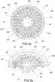
figure 3a shows a top view of the inner bottom of a capsule according to a first variant embodiment; -
figure 3b shows a perspective sectional view of the variant offigure 3a ; -
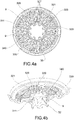
figure 4a shows a top view of the inner bottom of a capsule according to a second variant embodiment; -
figure 4b shows a perspective sectional view of the variant offigure 4a ; -
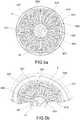
figure 5a shows a top view of the inner bottom of a capsule according to a third variant embodiment; -
figure 5b shows a perspective sectional view of the variant offigure 5a ; -
figure 6a shows a top view of the inner bottom of a capsule according to a fourth variant embodiment; -
figure 6b shows a perspective sectional view of the variant offigure 6a ; -
figure 7a shows a top view of the inner bottom of a capsule according to a fifth variant embodiment; -
figure 7b shows a perspective sectional view of the variant offigure 7a ; -
figure 8a shows a top view of the inner bottom of a capsule according to a sixth variant embodiment; -
figure 8b shows a perspective sectional view of the variant offigure 8a ; - With reference to the accompanying figures, a capsule for the preparation of infused or soluble beverages is shown, indicated at the reference number 1.
- Capsule 1 comprises a body or
cup 2 suitable for defining an internal volume V for containing at least onesubstance 11 to be infused or dissolved, typically in powder or granular form. - The
cup 2 is made of plastic material, preferably by injection or co-injection molding, or thermoformed. - The
cup 2 is provided, on the one side, with abottom 3 and, on the opposite side, with an inlet opening 21 defined by anedge 4 protruding outward. - The capsule 1 comprises a
cover 6 fixed by bonding or welding to theupper edge 4 adapted to seal thecup 2 at the top. - The
cup 2 is provided externally on thebottom 3 with an outlet opening 31, defined by anozzle 32, adapted to allow the outflow of the infused beverage. - The
cup 2 is provided internally at thebottom 3 with aninner base 33 provided with a plurality ofreliefs same base 33. The reliefs protrude toward the inside of thecup 2, toward thecover 6. Advantageously, the top surface of thereliefs - As shown in
figures 3 and8 , thebase 33 comprises acentral portion 310 defined by a first relief covering the outlet opening 31 of thenozzle 32. Thecentral portion 310 is provided with at least one connection opening 311 between the inside of thecup 2 and the outlet opening 31 to allow the flow of the infused beverage out of the capsule 1. Preferably, thecentral portion 310 comprises a plurality ofconnection openings 311. - The
base 33 comprises alabyrinth 30 adapted to prevent, by capillarity, the passage of the infused beverage towards thenozzle 32 when the pressure inside the capsule 1 drops below a threshold value or ceases altogether when the capsule 1 is disengaged from the infuser group of the machine. Thelabyrinth 30 is defined by a plurality of reliefs calledlabyrinth portions 320. - The
base 33 comprises anouter edge 360, defined by a further relief, on which asealing disc 5 is fixed in a partially releasable manner, i.e. in a peelable manner by gluing or welding. - The capsule 1 is therefore internally provided with a
sealing disk 5 located at thebase 33 and adapted to seal thecup 2 on the bottom. The capsule 1 is thus provided with a closedchamber 12, defined at the top by thecover 6 and at the bottom by thedisc 5, within which thesubstance 11 to be infused or dissolved is contained. - The
disc 5 is made of plastic, multilayer or single layer, or of aluminum, or of a plastic/aluminum composite material. - The
disc 5 is positioned between the inner volume V and thebase 33, below thesubstance 11, fixed on thereliefs - The
disc 5 is then fixed on theedge 360, on thelabyrinth 30 and on thecentral portion 310. - Preferably, the
disc 5 is peelably fixed at least on the upper surface of therelief 360 of thebase 33, so as to detach therefrom as a result of the pressure increase inside the capsule 1. - In use inside an infused beverage preparation machine, which pierces the
cover 6 and injects the fluid under pressure into thecup 2, the pressure exerted by the fluid rises until the opening pressure is reached (for example between 4 and 8 bar), which pushes on thedisc 5 until the capsule 1 opens. In particular, due to the increase in pressure inside the capsule 1, thedisc 5 deforms until it separates from theedge 360 of thebase 33. Such separation causes the sealing effect previously ensured by the sealingdisc 5 to fail. - Preferably, between the
edge 360 and thelabyrinth 30, there is defined at the base 33 acollecting depression 330 adapted to collect the infused beverage and to allow the outflow thereof toward thelabyrinth 30. - Preferably, between the
labyrinth 30 and thecentral portion 310, there is defined at the base 33 a conveyingdepression 340 adapted to collect the infused beverage and to allow it to flow through theopenings 311 towards thenozzle 32, and outside of the capsule 1. - Preferably, the capsule 1 is provided, at the
base 33, withsupports 90 adapted to accompany the deformation of thedisc 5 in such a way that it does not tear or break, and keeps the disc raised in such a way that it does not adhere to the bottom of thecollecting depression 330. According to the invention thesupports 90 are arranged inside the collectingdepression 330 between thelabyrinth 30 and theedge 360. - Preferably, the
base 33 also comprises, inside of thecollecting depression 330, a plurality ofsupports 350, defined by further reliefs, arranged between thelabyrinth 30 and theedge 360. The supports 350, substantially in the form of a circumferential arc, define a plurality ofrecesses 351 or compartments. In particular, arecess 351 is defined between a pair ofadjacent supports 350. Advantageously, therecess 351 defines a preferential space for the deformation of thedisc 5. - As already mentioned, in the known capsules, the problem of dripping of residual fluids still contained inside the cup at the end of the dispensing cycle, in particular when the capsule is removed from the infusion chamber, is highlighted.
- Advantageously, the capsule 1 according to the present invention is provided with an anti-drip system which, exploiting the principle of capillarity, prevents the fluids remaining inside the
cup 2 from leaking out. - The
base 33 comprises in effect thelabyrinth 30. - The
labyrinth 30 comprises a plurality oflabyrinth portions 320 which define a plurality ofcapillary channels 321. - Each
labyrinth portion 320 develops radially with respect to thebase 33, between the collectingdepression 330 and the conveyingdepression 340. - According to the invention, Each
capillary channel 321 connects the collectingdepression 330 with the conveyingdepression 340 and defines an outflow path for the infused beverage towards the outlet opening 31. - The
capillary channel 321 is defined between twoadjacent labyrinth portions 30 and is closed at the top by thedisc 5, as shown infigures 2a and 2b . - The
capillary channel 321 is defined between aninlet 326 and anoutlet 327. - The
outlet 327 of thecapillary channel 321 flows into the conveyingdepression 340. - In order to optimize the capillary effect provided by the
labyrinth 30 and to provide a particularly effective anti-drip system, some measures have been adopted. - In particular, the section of the
capillary channel 321 is between 0.01 mm2 and 0.3 mm2, preferably between 0.08 mm2 and 0.15 mm2, even more preferably 0.1 mm2. Such section allows, on the one hand, to achieve the outflow of the infused beverage under pressure (between 4 bar and 8 bar), and on the other, to effectively retain the residual fluids inside thecup 2 when the pressure drops below a threshold value. - In the embodiment of
figure 2a , the section of thecapillary channel 321 is polygonal, preferably square or rectangular. - In the variant embodiment of
figure 2b , the section of thecapillary channel 321 is at least partly curved. - To define the section of the
capillary channel 321 in terms of base b and height h: preferably the base b is between 0.1 mm and 0.5 mm, even more preferably 0.3 mm; preferably the height h is between 0.1 mm and 0.6 mm, even more preferably between 0.3 mm and 0.4 mm. - The length of the
capillary channel 321 being defined as LC, measured as the length of the path between theinlet 326 and theoutlet 327, and the radial length of thelabyrinth 30 as LL, measured as the radial distance between theinlet 326 and the outlet 327: the length LC of thecapillary channel 321 is greater than the radial length LL of the labyrinth 30 (LC> LL). - Preferably, the ratio between the length LC of the
capillary channel 321 and the radial length LL of the labyrinth 30 (LC/LL) is between 1.5 and 5, preferably between 2 and 3. - Preferably, the
capillary channel 321 has a tortuous pattern. - The
capillary channel 321 comprises at least onecurve 328 or one change of direction. - In the embodiments shown in
figures 3 to 6 , thecapillary channel 321 comprises a plurality of angled curves, preferably at 90° angles. - In the embodiments shown in
figures 3 ,4 ,5 ,6 and7 , thecapillary channel 321 has a substantially radial pattern. - In the embodiments shown in
figures 3 to 5 , thecapillary channel 321 has a zigzag or "square wave" pattern. - In the variant of
figure 7 , thecapillary channel 321 has a radial and circumferential pattern. - In the variant of
figure 8 , thecapillary channel 321 has a winding line pattern. - The
labyrinth 30 comprises a number ofcapillary channels 321 ranging from 10 to 40, preferably 20 to 30. This solution makes it possible to exploit all the space available between the collectingdepression 330 and the conveyingdepression 340, in order to makecapillary channels 321 that are sufficiently narrow and long. - Advantageously, the
capillary channels 321 as described above with regard to theembodiments 3 to 8 are provided with a particularly thin section and a length that retains the residual liquid by capillarity, so as to considerably reduce and even eliminate dripping when the pressure inside of the capsule drops below a threshold value or ceases completely. - Preferably, in an embodiment as shown in
figures 4 and5 , all thecapillary channels 321 flow into the conveyingdepression 340 at abank 9. That is, theoutlet 327 of eachcapillary channel 321 faces abank 9. That is to say, none of theoutlets 327 of thecapillary channels 321 directly faces aconnection opening 311. - The
bank 9 is a relief arranged within the conveyingdepression 340. - The
bank 9 is a relief arranged circumferentially between thelabyrinth 30 and theconnection opening 311. - Such solution keeps the flow of the infused beverage from being directly channeled into a
connection opening 311 towards thenozzle 32, reducing the vorticity of the flow leaving the capsule 1 and thus eliminating splashing. - The capsule 1 may be made in different versions, for example, for the preparation of infused beverages (for example coffee or tea) or soluble beverages.
- Preferably, the coffee capsule 1 comprises a fixed filter under the
substance 11 and just above thedisk 5. - Preferably, the coffee capsule 1 further comprises a permeable or micro-perforated film, fixed at a certain distance above the
substance 11. - The capsule 1, in its different variant embodiments, may be used for the impromptu preparation of beverages (such as tea, coffee, herbal teas, milk, chocolate, etc.) by means of automatic or semi-automatic machines equipped with a dispensing unit adapted to produce an infusion via the passage of pressurized hot water through the capsule 1.
- A capsule according to the present invention may be used for the packaging of concentrated products (in the form of powder or granules or leaves) in predetermined and single-use doses, for the impromptu preparation of beverages such as leaf or soluble tea, powdered or instant coffee, herbal teas, milk, chocolate, or other dehydrated and soluble products.
- Innovatively, a capsule for the preparation of infused or soluble beverages according to the present invention is provided with a
labyrinth portion 30 which acts as an anti-drip system. Thelabyrinth portion 30, exploiting the principle of capillarity, prevents the fluids remaining inside thecup 2 from leaking out once the capsule is disengaged from the infuser group of the preparation machine. - Advantageously, in a variant embodiment of the capsule according to the present invention, all the
capillary channels 321 flow at abank 9 in such a way as to avoid that the flow of the infused beverage is directly channeled into aconnection opening 311 towards thenozzle 32, reducing vorticity and eliminating splashes.
Claims (9)
- Capsule (1) for preparing infusion or soluble beverages, comprising a cup (2) adapted to define an inner volume (V) for containing at least one substance (11) to be infused or dissolved,
said cup (2) being closed at the top by a cover (6) and provided with:on the opposite side of the cover (6), an opening (31) for the exit of the infused beverage; internally with a base (33) having reliefs projecting towards the cover (6) ;internally with a sealing disc (5), fixed between the inner volume (V) and the reliefs, adapted to inferiorly seal the capsule (1);said base (33) comprising a labyrinth (30) having a plurality of labyrinth portions (320), adapted to prevent the passage by capillarity of the infused beverage towards the opening (31) when the pressure inside the capsule (1) falls below a threshold value;characterized in that said labyrinth (30) comprises a plurality of capillary channels (321), each channel (321) being defined between two adjacent labyrinth portions (30) and superiorly closed by the sealing disc (5), wherein the section of the capillary channels (321) is between 0.01 mm2 and 0.3 mm2, preferably between 0.08 mm2 and 0.15 mm2,and in that each labyrinth portion (320) develops radially with respect to the base (33), between a collecting depression (330), defined between an outer edge (360) and the labyrinth (30), and a conveying depression (340), defined between the labyrinth (30) and a central portion (310), and in that each capillary channel (321) connects the collecting depression (330 with the conveying depression (340). - Capsule (1) according to claim 1, wherein having defined the section of the capillary channel (321) in terms of base (b) and height (h), the base (b) is between 0.1 mm and 0.5 mm, and the height (h) is between 0.1 mm and 0.6 mm.
- Capsule (1) according to claim 1 or 2, wherein the length (LC) of the capillary channel (321), measured as the distance of the path between an inlet (326) and an outlet (327), is greater than the length (LL) of the labyrinth (30), measured as radial distance (LL) between the inlet (326) and the outlet (327).
- Capsule (1) according to claim 3, wherein the ratio between the length (LC) of the capillary channel (321) and the length (LL) of the labyrinth (30) is between 1.5 and 5, preferably between 2 and 3.
- Capsule (1) according to any one of the preceding claims, wherein the labyrinth (30) comprises a number of capillary channels (321) between 10 and 40, preferably between 20 and 30.
- Capsule (1) according to any one of the preceding claims, wherein the capillary channel (321) has a zigzag or a "square wave" or a winding line pattern.
- Capsule (1) according to any one of the preceding claims, wherein the capillary channel (321) has a tortuous pattern, i.e. comprises a plurality of angled curves, preferably with 90° angles.
- Capsule (1) according to any one of the preceding claims, wherein an inlet (326) and an outlet (327) being defined for each capillary channel (321), all the capillary channels (321) flow at a bank (9), i.e. a relief arranged circumferentially between the labyrinth (30) and the opening (31) for the exit of the infused beverage.
- Capsule (1) according to any one of the preceding claims, wherein the disc (5) is fixed in a peelable manner on an edge (360) of the base (33) in order to separate therefrom at least partially due to the increase of pressure within the capsule (1), and wherein the opening of the capsule (1) for the exit of the infused beverage occurs by deformation of the disc (5) as a result of the pressure exerted by the fluid inside the capsule (1).
Applications Claiming Priority (2)
| Application Number | Priority Date | Filing Date | Title |
|---|---|---|---|
| IT102017000019425A IT201700019425A1 (en) | 2017-02-21 | 2017-02-21 | CAP FOR INFUSION OR SOLUBLE DRINKS EQUIPPED WITH AN ANTI-DROP SYSTEM |
| PCT/IB2018/051033 WO2018154437A1 (en) | 2017-02-21 | 2018-02-20 | Capsule for infusion and soluble beverages with anti-drip system |
Publications (2)
| Publication Number | Publication Date |
|---|---|
| EP3585708A1 EP3585708A1 (en) | 2020-01-01 |
| EP3585708B1 true EP3585708B1 (en) | 2021-01-20 |
Family
ID=59253876
Family Applications (1)
| Application Number | Title | Priority Date | Filing Date |
|---|---|---|---|
| EP18712456.5A Active EP3585708B1 (en) | 2017-02-21 | 2018-02-20 | Capsule for infusion and soluble beverages with anti-drip system |
Country Status (7)
| Country | Link |
|---|---|
| US (1) | US20190367260A1 (en) |
| EP (1) | EP3585708B1 (en) |
| CN (1) | CN110312665B (en) |
| ES (1) | ES2871375T3 (en) |
| IT (1) | IT201700019425A1 (en) |
| RU (1) | RU2743305C1 (en) |
| WO (1) | WO2018154437A1 (en) |
Families Citing this family (7)
| Publication number | Priority date | Publication date | Assignee | Title |
|---|---|---|---|---|
| AU2018235278B2 (en) * | 2017-03-17 | 2023-04-13 | Caffitaly System S.P.A. | Capsule for the preparation of beverages |
| IT201700029991A1 (en) | 2017-03-17 | 2018-09-17 | Caffitaly System Spa | CAPSULE FOR THE PREPARATION OF A BEVERAGE |
| WO2019204914A1 (en) * | 2018-04-23 | 2019-10-31 | 2266170 Ontario Inc. | Capsules, beverage brewing systems and fabrics with optimum filtration characteristics |
| CA3119772A1 (en) * | 2018-11-15 | 2020-05-22 | BetaPod, Inc. | System comprising a machine for preparing a smokable product from a portion capsule |
| ES1235376Y (en) * | 2019-07-09 | 2019-12-18 | Cocatech S L U | DRINK INFUSION CAPSULE |
| US20220240712A1 (en) * | 2021-02-03 | 2022-08-04 | Haier Us Appliance Solutions, Inc. | Drip-resistant beverage dispenser for an appliance |
| IT202100009392A1 (en) * | 2021-04-14 | 2022-10-14 | Bisio Progetti Spa | CUP FOR A CAPSULE FOR INFUSION OR SOLUBLE DRINKS, AND RELATIVE CAPSULE |
Family Cites Families (10)
| Publication number | Priority date | Publication date | Assignee | Title |
|---|---|---|---|---|
| MY150418A (en) * | 2007-03-23 | 2014-01-15 | Nestec Sa | Beverage ingredient capsule with opening plate having pressure-relief openings |
| US8499682B2 (en) * | 2008-02-06 | 2013-08-06 | Nestec S.A. | Labyrinth capsule for drink powder |
| SG188913A1 (en) * | 2008-03-18 | 2013-04-30 | Nestec Sa | Cartridge for preparation of a liquid comprising puncturable delivery wall |
| ES2398277B2 (en) * | 2012-08-28 | 2013-12-18 | Unión Tostadora, S.A. | Beverage capsule and capsule manufacturing method |
| PL2981482T3 (en) * | 2013-04-03 | 2019-11-29 | Douwe Egberts Bv | Coffee pad for use in a coffee machine |
| WO2015121881A1 (en) * | 2014-02-12 | 2015-08-20 | Bisio Progetti S.P.A. | Capsule for preparing infusion beverages |
| ES2897923T3 (en) * | 2014-02-12 | 2022-03-03 | Bisio Progetti Spa | Capsule to prepare infusion drinks |
| ES2578189B1 (en) * | 2015-01-21 | 2017-06-29 | Segundo PATIÑO PATIÑO | Capsule for the preparation of a drink |
| WO2016135581A1 (en) * | 2015-02-27 | 2016-09-01 | Bisio Progetti S.P.A. | Capsule for the preparation of infused or soluble beverages |
| ITUA20161349A1 (en) * | 2016-03-04 | 2017-09-04 | Bisio Progetti Spa | Improved capsule for the preparation of infusion and soluble beverages |
-
2017
- 2017-02-21 IT IT102017000019425A patent/IT201700019425A1/en unknown
-
2018
- 2018-02-20 CN CN201880013025.1A patent/CN110312665B/en active Active
- 2018-02-20 RU RU2019125955A patent/RU2743305C1/en active
- 2018-02-20 US US16/487,553 patent/US20190367260A1/en not_active Abandoned
- 2018-02-20 ES ES18712456T patent/ES2871375T3/en active Active
- 2018-02-20 WO PCT/IB2018/051033 patent/WO2018154437A1/en active Application Filing
- 2018-02-20 EP EP18712456.5A patent/EP3585708B1/en active Active
Non-Patent Citations (1)
| Title |
|---|
| None * |
Also Published As
| Publication number | Publication date |
|---|---|
| WO2018154437A1 (en) | 2018-08-30 |
| ES2871375T3 (en) | 2021-10-28 |
| CN110312665A (en) | 2019-10-08 |
| BR112019014927A2 (en) | 2020-03-31 |
| RU2743305C1 (en) | 2021-02-16 |
| IT201700019425A1 (en) | 2018-08-21 |
| CN110312665B (en) | 2021-10-08 |
| US20190367260A1 (en) | 2019-12-05 |
| EP3585708A1 (en) | 2020-01-01 |
Similar Documents
| Publication | Publication Date | Title |
|---|---|---|
| EP3585708B1 (en) | Capsule for infusion and soluble beverages with anti-drip system | |
| EP3423380B1 (en) | Improved capsule for the preparation of infused or soluble beverages | |
| EP3261958B1 (en) | Capsule for preparation of infused or soluble beverages | |
| EP2837312B2 (en) | A system for preparing a beverage starting from an infusion product contained in an interchangeable capsule | |
| RU2693949C1 (en) | Single-dose capsule for machines for dispensing brewed beverages | |
| KR20130033447A (en) | A capsule for preparation of a food product from a food preparation machine | |
| EP3419917B1 (en) | A capsule for producing a beverage | |
| EP3071495B1 (en) | Capsule for preparing infusion beverages | |
| CN110431090B (en) | Cartridge for preparing infusions or soluble beverages in a low pressure extraction system | |
| RU2750789C2 (en) | Capsule for making drinks | |
| EP3494070B1 (en) | Capsule for the preparation of infusion and soluble beverages | |
| CN116529179A (en) | Capsule and system for preparing a beverage | |
| RU2734269C1 (en) | Beverage preparation capsule | |
| EP3728076B1 (en) | Beverage preparation capsule | |
| EP3532407B1 (en) | Beverage preparation capsule | |
| RU2749849C2 (en) | Capsule for preparing beverages | |
| BR112019014927B1 (en) | CAPSULE FOR SOLUBLE OR INFUSION BEVERAGES WITH NO DRIPPING SYSTEM | |
| IT201800004732A1 (en) | CAPSULE FOR THE PREPARATION OF BEVERAGES | |
| WO2018020391A1 (en) | Capsule for the preparation of beverages, having an easily perforable bottom |
Legal Events
| Date | Code | Title | Description |
|---|---|---|---|
| STAA | Information on the status of an ep patent application or granted ep patent |
Free format text: STATUS: UNKNOWN |
|
| STAA | Information on the status of an ep patent application or granted ep patent |
Free format text: STATUS: THE INTERNATIONAL PUBLICATION HAS BEEN MADE |
|
| PUAI | Public reference made under article 153(3) epc to a published international application that has entered the european phase |
Free format text: ORIGINAL CODE: 0009012 |
|
| STAA | Information on the status of an ep patent application or granted ep patent |
Free format text: STATUS: REQUEST FOR EXAMINATION WAS MADE |
|
| 17P | Request for examination filed |
Effective date: 20190712 |
|
| AK | Designated contracting states |
Kind code of ref document: A1 Designated state(s): AL AT BE BG CH CY CZ DE DK EE ES FI FR GB GR HR HU IE IS IT LI LT LU LV MC MK MT NL NO PL PT RO RS SE SI SK SM TR |
|
| AX | Request for extension of the european patent |
Extension state: BA ME |
|
| DAV | Request for validation of the european patent (deleted) | ||
| DAX | Request for extension of the european patent (deleted) | ||
| GRAP | Despatch of communication of intention to grant a patent |
Free format text: ORIGINAL CODE: EPIDOSNIGR1 |
|
| STAA | Information on the status of an ep patent application or granted ep patent |
Free format text: STATUS: GRANT OF PATENT IS INTENDED |
|
| INTG | Intention to grant announced |
Effective date: 20201023 |
|
| RIN1 | Information on inventor provided before grant (corrected) |
Inventor name: ROBOTTI, PAOLO |
|
| GRAS | Grant fee paid |
Free format text: ORIGINAL CODE: EPIDOSNIGR3 |
|
| GRAA | (expected) grant |
Free format text: ORIGINAL CODE: 0009210 |
|
| STAA | Information on the status of an ep patent application or granted ep patent |
Free format text: STATUS: THE PATENT HAS BEEN GRANTED |
|
| AK | Designated contracting states |
Kind code of ref document: B1 Designated state(s): AL AT BE BG CH CY CZ DE DK EE ES FI FR GB GR HR HU IE IS IT LI LT LU LV MC MK MT NL NO PL PT RO RS SE SI SK SM TR |
|
| REG | Reference to a national code |
Ref country code: GB Ref legal event code: FG4D |
|
| REG | Reference to a national code |
Ref country code: CH Ref legal event code: EP |
|
| REG | Reference to a national code |
Ref country code: DE Ref legal event code: R096 Ref document number: 602018012066 Country of ref document: DE |
|
| REG | Reference to a national code |
Ref country code: AT Ref legal event code: REF Ref document number: 1356210 Country of ref document: AT Kind code of ref document: T Effective date: 20210215 |
|
| REG | Reference to a national code |
Ref country code: IE Ref legal event code: FG4D |
|
| REG | Reference to a national code |
Ref country code: NL Ref legal event code: MP Effective date: 20210120 |
|
| REG | Reference to a national code |
Ref country code: LT Ref legal event code: MG9D |
|
| REG | Reference to a national code |
Ref country code: AT Ref legal event code: MK05 Ref document number: 1356210 Country of ref document: AT Kind code of ref document: T Effective date: 20210120 |
|
| PG25 | Lapsed in a contracting state [announced via postgrant information from national office to epo] |
Ref country code: NO Free format text: LAPSE BECAUSE OF FAILURE TO SUBMIT A TRANSLATION OF THE DESCRIPTION OR TO PAY THE FEE WITHIN THE PRESCRIBED TIME-LIMIT Effective date: 20210420 Ref country code: PT Free format text: LAPSE BECAUSE OF FAILURE TO SUBMIT A TRANSLATION OF THE DESCRIPTION OR TO PAY THE FEE WITHIN THE PRESCRIBED TIME-LIMIT Effective date: 20210520 Ref country code: LT Free format text: LAPSE BECAUSE OF FAILURE TO SUBMIT A TRANSLATION OF THE DESCRIPTION OR TO PAY THE FEE WITHIN THE PRESCRIBED TIME-LIMIT Effective date: 20210120 Ref country code: GR Free format text: LAPSE BECAUSE OF FAILURE TO SUBMIT A TRANSLATION OF THE DESCRIPTION OR TO PAY THE FEE WITHIN THE PRESCRIBED TIME-LIMIT Effective date: 20210421 Ref country code: FI Free format text: LAPSE BECAUSE OF FAILURE TO SUBMIT A TRANSLATION OF THE DESCRIPTION OR TO PAY THE FEE WITHIN THE PRESCRIBED TIME-LIMIT Effective date: 20210120 Ref country code: HR Free format text: LAPSE BECAUSE OF FAILURE TO SUBMIT A TRANSLATION OF THE DESCRIPTION OR TO PAY THE FEE WITHIN THE PRESCRIBED TIME-LIMIT Effective date: 20210120 Ref country code: BG Free format text: LAPSE BECAUSE OF FAILURE TO SUBMIT A TRANSLATION OF THE DESCRIPTION OR TO PAY THE FEE WITHIN THE PRESCRIBED TIME-LIMIT Effective date: 20210420 |
|
| PG25 | Lapsed in a contracting state [announced via postgrant information from national office to epo] |
Ref country code: SE Free format text: LAPSE BECAUSE OF FAILURE TO SUBMIT A TRANSLATION OF THE DESCRIPTION OR TO PAY THE FEE WITHIN THE PRESCRIBED TIME-LIMIT Effective date: 20210120 Ref country code: AT Free format text: LAPSE BECAUSE OF FAILURE TO SUBMIT A TRANSLATION OF THE DESCRIPTION OR TO PAY THE FEE WITHIN THE PRESCRIBED TIME-LIMIT Effective date: 20210120 Ref country code: PL Free format text: LAPSE BECAUSE OF FAILURE TO SUBMIT A TRANSLATION OF THE DESCRIPTION OR TO PAY THE FEE WITHIN THE PRESCRIBED TIME-LIMIT Effective date: 20210120 Ref country code: RS Free format text: LAPSE BECAUSE OF FAILURE TO SUBMIT A TRANSLATION OF THE DESCRIPTION OR TO PAY THE FEE WITHIN THE PRESCRIBED TIME-LIMIT Effective date: 20210120 Ref country code: LV Free format text: LAPSE BECAUSE OF FAILURE TO SUBMIT A TRANSLATION OF THE DESCRIPTION OR TO PAY THE FEE WITHIN THE PRESCRIBED TIME-LIMIT Effective date: 20210120 |
|
| PG25 | Lapsed in a contracting state [announced via postgrant information from national office to epo] |
Ref country code: IS Free format text: LAPSE BECAUSE OF FAILURE TO SUBMIT A TRANSLATION OF THE DESCRIPTION OR TO PAY THE FEE WITHIN THE PRESCRIBED TIME-LIMIT Effective date: 20210520 |
|
| REG | Reference to a national code |
Ref country code: DE Ref legal event code: R097 Ref document number: 602018012066 Country of ref document: DE |
|
| REG | Reference to a national code |
Ref country code: BE Ref legal event code: MM Effective date: 20210228 |
|
| REG | Reference to a national code |
Ref country code: ES Ref legal event code: FG2A Ref document number: 2871375 Country of ref document: ES Kind code of ref document: T3 Effective date: 20211028 |
|
| PG25 | Lapsed in a contracting state [announced via postgrant information from national office to epo] |
Ref country code: CH Free format text: LAPSE BECAUSE OF NON-PAYMENT OF DUE FEES Effective date: 20210228 Ref country code: SM Free format text: LAPSE BECAUSE OF FAILURE TO SUBMIT A TRANSLATION OF THE DESCRIPTION OR TO PAY THE FEE WITHIN THE PRESCRIBED TIME-LIMIT Effective date: 20210120 Ref country code: MC Free format text: LAPSE BECAUSE OF FAILURE TO SUBMIT A TRANSLATION OF THE DESCRIPTION OR TO PAY THE FEE WITHIN THE PRESCRIBED TIME-LIMIT Effective date: 20210120 Ref country code: LU Free format text: LAPSE BECAUSE OF NON-PAYMENT OF DUE FEES Effective date: 20210220 Ref country code: LI Free format text: LAPSE BECAUSE OF NON-PAYMENT OF DUE FEES Effective date: 20210228 Ref country code: CZ Free format text: LAPSE BECAUSE OF FAILURE TO SUBMIT A TRANSLATION OF THE DESCRIPTION OR TO PAY THE FEE WITHIN THE PRESCRIBED TIME-LIMIT Effective date: 20210120 Ref country code: EE Free format text: LAPSE BECAUSE OF FAILURE TO SUBMIT A TRANSLATION OF THE DESCRIPTION OR TO PAY THE FEE WITHIN THE PRESCRIBED TIME-LIMIT Effective date: 20210120 |
|
| PLBE | No opposition filed within time limit |
Free format text: ORIGINAL CODE: 0009261 |
|
| STAA | Information on the status of an ep patent application or granted ep patent |
Free format text: STATUS: NO OPPOSITION FILED WITHIN TIME LIMIT |
|
| PG25 | Lapsed in a contracting state [announced via postgrant information from national office to epo] |
Ref country code: DK Free format text: LAPSE BECAUSE OF FAILURE TO SUBMIT A TRANSLATION OF THE DESCRIPTION OR TO PAY THE FEE WITHIN THE PRESCRIBED TIME-LIMIT Effective date: 20210120 Ref country code: SK Free format text: LAPSE BECAUSE OF FAILURE TO SUBMIT A TRANSLATION OF THE DESCRIPTION OR TO PAY THE FEE WITHIN THE PRESCRIBED TIME-LIMIT Effective date: 20210120 Ref country code: RO Free format text: LAPSE BECAUSE OF FAILURE TO SUBMIT A TRANSLATION OF THE DESCRIPTION OR TO PAY THE FEE WITHIN THE PRESCRIBED TIME-LIMIT Effective date: 20210120 |
|
| 26N | No opposition filed |
Effective date: 20211021 |
|
| PG25 | Lapsed in a contracting state [announced via postgrant information from national office to epo] |
Ref country code: IE Free format text: LAPSE BECAUSE OF NON-PAYMENT OF DUE FEES Effective date: 20210220 Ref country code: AL Free format text: LAPSE BECAUSE OF FAILURE TO SUBMIT A TRANSLATION OF THE DESCRIPTION OR TO PAY THE FEE WITHIN THE PRESCRIBED TIME-LIMIT Effective date: 20210120 |
|
| PG25 | Lapsed in a contracting state [announced via postgrant information from national office to epo] |
Ref country code: SI Free format text: LAPSE BECAUSE OF FAILURE TO SUBMIT A TRANSLATION OF THE DESCRIPTION OR TO PAY THE FEE WITHIN THE PRESCRIBED TIME-LIMIT Effective date: 20210120 |
|
| PG25 | Lapsed in a contracting state [announced via postgrant information from national office to epo] |
Ref country code: IS Free format text: LAPSE BECAUSE OF FAILURE TO SUBMIT A TRANSLATION OF THE DESCRIPTION OR TO PAY THE FEE WITHIN THE PRESCRIBED TIME-LIMIT Effective date: 20210520 |
|
| PG25 | Lapsed in a contracting state [announced via postgrant information from national office to epo] |
Ref country code: BE Free format text: LAPSE BECAUSE OF NON-PAYMENT OF DUE FEES Effective date: 20210228 |
|
| PGFP | Annual fee paid to national office [announced via postgrant information from national office to epo] |
Ref country code: FR Payment date: 20230227 Year of fee payment: 6 Ref country code: ES Payment date: 20230301 Year of fee payment: 6 |
|
| PGFP | Annual fee paid to national office [announced via postgrant information from national office to epo] |
Ref country code: IT Payment date: 20230109 Year of fee payment: 6 Ref country code: GB Payment date: 20230221 Year of fee payment: 6 Ref country code: DE Payment date: 20230216 Year of fee payment: 6 |
|
| P01 | Opt-out of the competence of the unified patent court (upc) registered |
Effective date: 20230519 |
|
| PG25 | Lapsed in a contracting state [announced via postgrant information from national office to epo] |
Ref country code: NL Free format text: LAPSE BECAUSE OF NON-PAYMENT OF DUE FEES Effective date: 20210120 Ref country code: CY Free format text: LAPSE BECAUSE OF FAILURE TO SUBMIT A TRANSLATION OF THE DESCRIPTION OR TO PAY THE FEE WITHIN THE PRESCRIBED TIME-LIMIT Effective date: 20210120 |
|
| PG25 | Lapsed in a contracting state [announced via postgrant information from national office to epo] |
Ref country code: HU Free format text: LAPSE BECAUSE OF FAILURE TO SUBMIT A TRANSLATION OF THE DESCRIPTION OR TO PAY THE FEE WITHIN THE PRESCRIBED TIME-LIMIT; INVALID AB INITIO Effective date: 20180220 |
|
| PGFP | Annual fee paid to national office [announced via postgrant information from national office to epo] |
Ref country code: ES Payment date: 20240301 Year of fee payment: 7 |