EP3585685B1 - Flugsystem - Google Patents
Flugsystem Download PDFInfo
- Publication number
- EP3585685B1 EP3585685B1 EP18708178.1A EP18708178A EP3585685B1 EP 3585685 B1 EP3585685 B1 EP 3585685B1 EP 18708178 A EP18708178 A EP 18708178A EP 3585685 B1 EP3585685 B1 EP 3585685B1
- Authority
- EP
- European Patent Office
- Prior art keywords
- propulsion
- user
- hand
- assembly
- thrust
- Prior art date
- Legal status (The legal status is an assumption and is not a legal conclusion. Google has not performed a legal analysis and makes no representation as to the accuracy of the status listed.)
- Active
Links
Images


Classifications
-
- B—PERFORMING OPERATIONS; TRANSPORTING
- B64—AIRCRAFT; AVIATION; COSMONAUTICS
- B64C—AEROPLANES; HELICOPTERS
- B64C15/00—Attitude, flight direction, or altitude control by jet reaction
- B64C15/02—Attitude, flight direction, or altitude control by jet reaction the jets being propulsion jets
-
- B—PERFORMING OPERATIONS; TRANSPORTING
- B64—AIRCRAFT; AVIATION; COSMONAUTICS
- B64C—AEROPLANES; HELICOPTERS
- B64C39/00—Aircraft not otherwise provided for
- B64C39/02—Aircraft not otherwise provided for characterised by special use
- B64C39/026—Aircraft not otherwise provided for characterised by special use for use as personal propulsion unit
-
- B—PERFORMING OPERATIONS; TRANSPORTING
- B64—AIRCRAFT; AVIATION; COSMONAUTICS
- B64D—EQUIPMENT FOR FITTING IN OR TO AIRCRAFT; FLIGHT SUITS; PARACHUTES; ARRANGEMENT OR MOUNTING OF POWER PLANTS OR PROPULSION TRANSMISSIONS IN AIRCRAFT
- B64D31/00—Power plant control systems; Arrangement of power plant control systems in aircraft
- B64D31/02—Initiating means
- B64D31/04—Initiating means actuated personally
-
- B—PERFORMING OPERATIONS; TRANSPORTING
- B64—AIRCRAFT; AVIATION; COSMONAUTICS
- B64D—EQUIPMENT FOR FITTING IN OR TO AIRCRAFT; FLIGHT SUITS; PARACHUTES; ARRANGEMENT OR MOUNTING OF POWER PLANTS OR PROPULSION TRANSMISSIONS IN AIRCRAFT
- B64D37/00—Arrangements in connection with fuel supply for power plant
- B64D37/02—Tanks
- B64D37/06—Constructional adaptations thereof
-
- B—PERFORMING OPERATIONS; TRANSPORTING
- B64—AIRCRAFT; AVIATION; COSMONAUTICS
- B64D—EQUIPMENT FOR FITTING IN OR TO AIRCRAFT; FLIGHT SUITS; PARACHUTES; ARRANGEMENT OR MOUNTING OF POWER PLANTS OR PROPULSION TRANSMISSIONS IN AIRCRAFT
- B64D45/00—Aircraft indicators or protectors not otherwise provided for
-
- F—MECHANICAL ENGINEERING; LIGHTING; HEATING; WEAPONS; BLASTING
- F02—COMBUSTION ENGINES; HOT-GAS OR COMBUSTION-PRODUCT ENGINE PLANTS
- F02C—GAS-TURBINE PLANTS; AIR INTAKES FOR JET-PROPULSION PLANTS; CONTROLLING FUEL SUPPLY IN AIR-BREATHING JET-PROPULSION PLANTS
- F02C6/00—Plural gas-turbine plants; Combinations of gas-turbine plants with other apparatus; Adaptations of gas-turbine plants for special use
-
- B—PERFORMING OPERATIONS; TRANSPORTING
- B64—AIRCRAFT; AVIATION; COSMONAUTICS
- B64D—EQUIPMENT FOR FITTING IN OR TO AIRCRAFT; FLIGHT SUITS; PARACHUTES; ARRANGEMENT OR MOUNTING OF POWER PLANTS OR PROPULSION TRANSMISSIONS IN AIRCRAFT
- B64D45/00—Aircraft indicators or protectors not otherwise provided for
- B64D2045/0085—Devices for aircraft health monitoring, e.g. monitoring flutter or vibration
Definitions
- the invention relates to an apparatus for enabling an individual to fly.
- the invention relates to the provision of propulsion assemblies that can be held in a user's hands and/or worn on a user's forearms and provide thrust to lift the user from the ground.
- the inventors have realised that it is possible to configure a flight system that can use the strength of the human body, rather than a rigid frame work, to provide stable flight for an individual.
- US 2014/196650 A1 discloses a motorized water vehicle adapted to operate as a fluidcompression station to supply a passenger propulsion device.
- US 2009/020654 A1 discloses a harness with mounted engine frame.
- propulsion assembly is meant a device that produces thrust.
- a propulsion assembly may comprise one or more propulsion units that each provide thrust (for example, in a known direction) and collectively define the thrust that is produced by the propulsion assembly.
- the thrust provided by a propulsion assembly produces an equal and opposite force on the user.
- each propulsion assembly is able to provide a maximum thrust of at least 400N and preferably at least 500N.
- Each propulsion assembly may be controllable to produce a lower thrust than the maximum based on control signals.
- the propulsion assemblies may comprise turbines or ducted fans.
- propulsion assemblies of the flight system may be mounted on the human body such that the “wearer” contributes at least in part to the relative motion of those propulsion assemblies. That is, it is recognised that the difficult control problem of correctly angling a variety of thrusts produced by a plurality of propulsion assemblies may be delegated to the wearer's natural senses of balance, proprioception, and kinaesthesia.
- Embodiments of the invention include a flight system comprising at least two propulsion assemblies that may be held in the hands and/or otherwise mounted on the wearer's forearms.
- net thrust is directed substantially in line with the user's respective forearm and away from the elbow so that the induced stress is generally aligned with the bones of the wearer's forearm and is directed outwardly.
- net thrust rather than all thrust.
- a suitably physically conditioned wearer is able to support his/her own weight using just his/her arms, but for longer usage, it is preferable to share some of the load with other parts of the wearer's skeleton or musculature.
- a body propulsion assembly arranged for engaging the wearer's torso to substantially prevent relative movement between the body propulsion assembly and the wearer's torso.
- one or more leg propulsion assemblies can be provided.
- the leg propulsion assemblies may be arranged for engaging one or both of the wearer's legs to substantially prevent relative movement between the leg propulsion assemblies and the wearer's corresponding leg(s).
- the maximum thrust capability of the left-hand and right-hand propulsion assemblies together is preferably equal to or greater than the maximum thrust capability of the other propulsion assemblies combined.
- the maximum thrust capability of the left-hand and right-hand propulsion assemblies together are preferably equal and the maximum thrust capability of each of the left-hand and right-hand propulsion assemblies is preferably equal to or greater than the maximum thrust capability of the other propulsion assemblies combined.
- Lift is produced by the combined vertical resolution of the forces generated by all of the propulsion assemblies. Whilst not essential, it is preferred for reasons of control and stability that the thrust generated by the left-hand and right-hand propulsion assemblies is equal. In order to control horizontal motion, the wearer can use his/her arms to direct the left-hand and right-hand propulsion assemblies to produce a net thrust that includes a horizontal component.
- a body propulsion assembly When a body propulsion assembly is provided, this may be inclined relative to the torso of the wearer (by virtue of the arrangement of a support through which it engages the wearer) so as to provide a small net forward force on the wearer, i.e. the thrust is directed rearwardly to produce a net force on the wearer in a forward direction perpendicular to a line extending between the centre of the user's head and the centre of the user's waist.
- the body propulsion assembly may provide a net forward force. That forward force may be counteracted by the wearer inclining his/her arms in front of his/her torso to provide an equal net thrust in the opposite direction.
- the assemblies are arranged such that collectively they can produce equilibrium (a net vertical thrust equal to the load of the wearer and flight system, with a zero net horizontal thrust) when in a splayed (i.e. divergent) arrangement.
- this also has the advantage that the exhaust of the propulsion assemblies is directed away from the wearer's body.
- a body propulsion assembly When a body propulsion assembly is provided, it is preferably arranged vertically at the same height as the left-hand and right-hand propulsion assemblies when in the splayed arrangement that produces equilibrium. It has been found that the preferred location on the body of the wearer is therefore in the region of the wearer's waist (that is, the thrust is generated near the wearer's waist). Preferably, the outlet of the thrust is no higher than the user's lumbar vertebrae and no lower than the user's thighs. Most preferably, the outlet of the thrust is aligned with the user's lumbar vertebrae.
- a fuel tank supplies fuel to the propulsion assemblies (for example, the fuel may supply turbines forming the propulsion units). Since the user is flying based on feel, it is important that the experience remains constant over time so that the user does not need to greatly re-calibrate his or her actions as the fuel is used up. Accordingly, the thrust provided by one or more or all of the propulsion assemblies can be automatically varied as a function of the stored fuel. That is the fuel use (or the remaining stored fuel) may be monitored, and the thrust provided by the propulsion assemblies may be used to compensate for the reduction in weight of the fuel load. Fuel use/remaining fuel may be measured directly, or inferred either by the use of one or more propulsion units.
- the thrust of a body propulsion assembly (since this will be located most closely to the fuel store) is varied as a function of the stored fuel.
- the thrust of the body propulsion assembly is automatically reduced to compensate for the reducing load of the fuel store as fuel is used.
- the propulsion assemblies configured to be worn on a user's hand or forearm may comprise at least two hand propulsion units in a splayed arrangement that produce thrusts that diverge such that their net thrust is substantially aligned with the wearer's arm. This has been found to add to the stability of the overall system.
- the flight system of the invention may be provided with or without one or more wings.
- the features set out below make it unnecessary to use a wing and it is preferred that one is not possible.
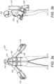
- a first embodiment of a propulsion assembly 100 for applying thrust directly to a user's arm is shown in Figures 1a to 1c .
- a flight system in accordance with the invention will have one propulsion assembly 100 for each arm.
- a propulsion assembly 100 comprises: one or more propulsion units 110; a sleeve 120; and one or more mountings 118.
- propulsion unit 110 there are two propulsion units 110, a first propulsion unit 110a, and a second propulsion unit 110b.
- propulsion unit 110a, 110b there is a mounting 118a, 118b via which the respective propulsion unit 110a, 110b is mounted to the sleeve 120.
- the sleeve 120 of the propulsion assembly 100 is configured to be worn on a user's hand and/or forearm. It is preferable that the sleeve 120 extends over a length of from 20cm to 50cm, and more preferably a length of from 30cm to 35cm, so that the propulsion assembly 100 is held in alignment with the user's arm, but does not hinder articulation of the elbow.
- the sleeve 120 defines a longitudinal axis, a distal end 121 and a proximal end 122. When the propulsion assembly 100 is worn, the distal end 121 is distal with respect to the user's body (e.g.
- the sleeve 120 may have a diameter in the range 8cm to 10cm.
- the sleeve 120 is padded on the inside.
- the padding may be shaped to the general contour of an arm so as to distribute support comfortably.
- the propulsion assembly 100 as a whole is arranged to provide a net thrust along an axis that generally corresponds with the user's forearm when the propulsion assembly 100 is worn. That is, the propulsion assembly 100 as a whole is arranged to provide a net thrust along the longitudinal axis of the sleeve 120.
- the first and second propulsion units 110a, 110b are angled apart so as to produce thrust along non-parallel vectors.
- the mountings 118a and 118b may include connecting members 130 that space the propulsion units 110a, 110b from the sleeve 120 by a greater amount at the distal end 121 than at the proximal end 122.
- the first propulsion unit 110a is arranged to provide net force along a first axis Xa defining a first propulsion vector.
- the second propulsion unit 110b is arranged to provide net force along a second axis Xb defining a second propulsion vector.
- the divergence of thrust can provide beneficial stability.
- the first propulsion vector is at least an angle of 5° relative to the second propulsion vector and more preferably at least an angle of 10°.
- the first propulsion vector is no more than an angle of 30° relative to the second propulsion vector and more preferably no more than 25°.
- the loss of thrust due to divergence can be balanced against the improved stability.
- a handle 124 for the user to grasp.
- the handle 124 may have mounted thereon controls 126.
- the controls 126 face the distal end 121 of the sleeve 120.
- the handle 124 is ergonomically-shaped so as to distribute the user's weight over as large an area of the user's hand as possible.
- a left-hand propulsion assembly 100 may have a left-handed grip 124, while a right-hand propulsion assembly 100 may have a right-handed grip 124.
- One or both of the left-hand grip 124 and right-hand grip 124 will have controls 126 mounted thereon.
- the handle is preferably positioned such that it is aligned with a line extending between the first and second propulsion units 110a, 110b. This defines the position of the first and second propulsion units 110a, 110b relative to the user's closed fist, and has been found to be particularly stable.
- the position of the handle 124 relative to the outlet(s) of the propulsion unit(s) 110 of the propulsion assembly 100 can influence stability. It is preferred that the handle 124 is spaced beyond the outlet(s) of the propulsion assembly 100 (e.g. the outlets of the first and second propulsion units 110a, 110b) by a distance in the range 20mm to 100mm, preferably by 30mm to 60mm, most preferably by 40mm. That is to say that the handle 124 may be spaced by this distance beyond the outlets in a direction corresponding to the axis of the net thrust
- the handle 124 may be spaced by this distance beyond the outlets in a direction corresponding to the longitudinal axis of the sleeve 120 if provided.
- the handle 124 may be spaced by this distance beyond the outlets in a direction corresponding to the axis that generally corresponds with the user's forearm when the propulsion assembly 100 is worn.
- the controls 126 preferably comprise two input devices.
- the first of the input devices provides a variable signal and can be used to control an amount of thrust produced by a propulsion assembly 100 (or a set of propulsion assemblies 100).
- the second of the input devices provides a binary output and can be used to deactivate one or more or (preferably) all of the propulsion assemblies 100 of the flight system when released. It is not essential that both left-hand and right-hand propulsion assemblies 100 include the second input device, though this may be preferred.
- the second of the input devices is preferably a "kill switch". That is, it must remain depressed by the user in order to prevent deactivation of the propulsion assemblies 100.
- the controls 126 are mounted on the handle so as to align with the thumb and forefinger of the user.
- the first input device is therefore preferably in the form of a trigger aligned with the user's index finger (when the handle is held in the user's hand).
- the second input device is preferably aligned with the user's thumb (when the handle is held in the user's hand) so that it can be continually held down during use of the flight system to prevent deactivation.
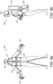
- FIG. 2a to 2c An example, not falling within the scope of the claims, of a propulsion assembly 200 for a user's torso is shown in Figures 2a to 2c . It is preferred that a flight system in accordance with the invention will have one such propulsion assembly 200.
- Body propulsion assembly 200 is configured to apply thrust directly to a user's torso and comprises at least one body propulsion unit 210 and a support 220.
- the support 220 is arranged to support a user's waist or torso.
- it may comprise a seat, harness, belt, jacket, and/or other item of clothing for securing the at least one body propulsion unit 210 to a user's body.
- the at least one body propulsion unit 210 is supported on the dorsal side of the user's body
- the support may be configured to be worn on a user's back or waist, but in either case it is preferable that the support is sized and shaped such that the location at which thrust is generated by the at least one body propulsion unit(s) 210 (i.e.
- the nozzle of the body propulsion unit(s) 210 when these are turbines and/or the fan of a fan driven by a motor) is located between the lower edge of the rib cage and knees, and more preferably between the upper extent of the lumbar vertebrae and the user's upper thigh.
- the support is sized and shaped such that the location at which thrust is generated by the at least one body propulsion unit(s) 210 (i.e. the nozzle of the body propulsion unit(s) 210 when these are turbines and/or the fan of a fan driven by a motor) is aligned with the lumbar vertebrae.
- the support 220 is arranged to hold the at least one body propulsion unit 210 at a fixed angle relative to the user's torso when the body propulsion assembly 200 is worn by (i.e. engages) the user.
- the support 220 defines an axis Z, which is parallel with a line extending between the centre of the user's head and the centre of the user's waist when the support is worn.
- the support 220 holds the at least one body propulsion unit 210 at an angle to the axis Z. That angle has an elevation component, the body propulsion elevation angle W. That is, the body propulsion elevation angle W is the angle in the sagittal plane (the plane that divides the user into left and right sides) between the net thrust produced by the body propulsion assembly 200 and the axis Z.
- the support 220 is configured to hold a user's body relative to the at least one body propulsion unit 210 such that a line extending between the centre of the user's head and the centre of the user's waist extends relative to the orientation of the net thrust provided by the body propulsion assembly 200 by the body propulsion elevation angle W.
- the body propulsion elevation angle W is greater than zero.
- the body propulsion elevation angle W is at least 10° and more preferably at least 12°. Even more preferably, the body propulsion elevation angle W is no more than 30° degrees and more preferably no more than 18°.
- leg braces 240 for engaging the user's upper thighs.
- a preferable leg brace 240 may comprise a section 244 arranged to extend between the user's legs so that the legs may grip the leg brace 240.
- the leg brace 240 may also have a wider section 242 on which a user may sit.
- the body propulsion assembly 200 preferably includes at least a first body propulsion unit 210a and a second body propulsion unit 210b.
- the first body propulsion unit 210a is arranged to provide net force along a first axis Ya defining a first propulsion vector.
- the second body propulsion unit 210b is arranged to provide net force along a second axis Yb defining a second propulsion vector.
- the first propulsion vector is not parallel with the second propulsion vector.
- the first and second propulsion vectors are directed apart by an angle of at least 5° and preferably at least 20°. Even more preferably, the first and second body propulsion vectors are directed apart by an angle of no more than 30°.
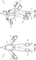
- FIG. 3a to 3e A first embodiment of a flight system is shown in Figures 3a to 3e , in which it can be seen that the system comprises a left-hand propulsion assembly 100 (of the type discussed above with reference to Figures 1a to 1c ); a right-hand propulsion assembly 100 (of the type discussed above with reference to Figures 1a to 1c ); a body propulsion assembly 200 (of the type discussed above with reference to Figures 2a to 2c ).
- each propulsion assembly 100, 200 is able to provide a maximum thrust in the range 400N to 500N.
- Figures 3a to 3e show the preferred embodiment in which two propulsion units 110 are provided for each of the left-hand and right-hand propulsion assemblies 100. Also preferred is the provision of two propulsion units 210 for the body propulsion assembly 200. That is, a combination of six propulsion units 110, 210, with two for each arm and two for the user's torso. Also shown is the above-described preferred rearward orientation of the propulsion units 210 of the body propulsion assembly 200 when the user assumes an upright standing posture.
- the support 220 of the body propulsion assembly 200 is sized and shaped to hold the body propulsion units 210 so that thrust is produced at a height between the lower edge of the rib cage and knees, and most preferably level with the lumbar vertebrae.
- the flight system 300 also comprises an energy storage device 310 for providing power to the propulsion assemblies.
- This may comprise a fuel storage vessel for supplying fuel to turbines and/or batteries for powering fans and/or control circuitry.
- the energy storage device 310 is preferably provided in the form of a back-pack to be worn above a lower-back-mounted or waist-mounted body propulsion assembly 200, or which may have one or more propulsion units attached thereto (for example, one either side of a central fuel storage vessel).
- the flight system 300 is preferably provided without a wing (i.e. it may be solely dependent upon the propulsion assemblies to provide lift), it is beneficial to minimise interruptions in the thrust provided by any one propulsion unit 110, 210, 410.
- the energy storage device 310 comprises a fuel storage vessel
- the vessel is provided as a variable volume storage (for example, a bladder or a cylinder closed by a piston) rather than a fixed volume chamber. In this way, no air will be present in the fuel storage vessel. 25.
- Preferable embodiments will comprise a bubble sensor for sensing the presence of bubbles in fuel supply lines for supplying fuel to turbines.
- the bubble sensor is for alerting the user to the presence of bubbles.
- the bubble sensor may provide a bubble signal representative of an amount of bubbles (volume or number, etc.) in the fuel line.
- the bubble signal exceeds a threshold, the user is alerted and may land, e.g. before the turbines fail.
- the alert may be audible or visual (for example using the head-up display described below).
- a control system 330 is provided. This may be embodied in a single device to be worn on the user's chest, or may be formed with distributed devices.
- the control system 330 is arranged to provide control signals to each propulsion assembly 100, 200.
- the control system 330 may also be arranged to receive control signals from each propulsion assembly 100, 200 and/or from the energy storage device 310.
- control system 330 may independently control the left-hand and right-hand propulsion assemblies 100, it is preferred that they each provide the same thrust.
- control signals may include: a first throttle signal generated by controls 126 of one of the left-hand and right-hand propulsion assemblies 100, and a second throttle signal generated by controls 126 of the other of the left-hand and right-hand propulsion assemblies 100.
- the control system 330 uses the first throttle signal to command the left-hand and right-hand propulsion assemblies 100 to each provide a corresponding first thrust.
- the control system 330 uses the second throttle signal to command the body propulsion assembly 200 to provide a second corresponding thrust.
- the controls 126 may be embodied as one or two input devices the left-hand and right-hand propulsion assemblies 100.
- one of the input devices provides a variable signal in the form of the throttle signal.
- the other of the input devices may be a "kill switch", which provides a binary output and is monitored by the control system 330 so as to deactivate one or more or (preferably) all of the propulsion assemblies 100 of the flight system when released.
- the flight system preferably includes a helmet 320 which comprises a head-up display in communication with the control system 330.
- the head-up display represents the amount of energy remaining in the energy storage device 310 (e.g., a volume of fuel remaining in the bladder) and/or the thrust of each of the propulsion assemblies 100, 200 (for example, the rotational speeds of the turbines).
- the flight system 300 of the first embodiment has been shown with a left-hand propulsion assembly 100, a right-hand propulsion assembly 100, and a body propulsion assembly 200
- the body propulsion assembly 200 is replaced by (as in the flight system 500 of Figures 5a to 5d ), or supplemented with, a leg propulsion assembly 400 (either one for both legs, or one for each leg).
- a leg propulsion assembly 400 comprises: at least one leg propulsion unit 410; and a support 420.
- the support 420 is preferably sized and shaped to be worn on a user's calf such that the at least one leg propulsion assembly 410 is on the dorsal side of the calf.
- the support 420 may comprise bindings for surrounding the user's leg such that the bindings define a longitudinal axis aligned with the bones of the lower leg.
- the support 420 is preferably sized and shaped to be worn on a user's calf such that the leg propulsion unit 410 is at an angle V to the longitudinal axis of the support 420 (i.e. is not aligned with the bones of the lower leg).
- angle V is such that when worn, there is a small force applied inwardly to press the user's legs towards one another. This provides divergence of thrust when a pair of leg propulsion assemblies 400 are worn and has been found to improve stability.
- the support 420 is preferably arranged such that the leg propulsion unit 410 is at an angle to the longitudinal axis of the support 420 of at least 3°.
- the support 420 is preferably arranged such that the leg propulsion unit 410 is at an angle to the longitudinal axis of the support 420 of no more than 20°. In this way, the leg propulsion units 410 at that angle to the user's leg when worn.
- the left-hand and right-hand propulsion assemblies 100 each included two propulsion units 110. Whilst that is preferred, more may be provided, and in fact only one is required. Thus, there is envisaged an example, not falling within the scope of the claims, of a flight system 600 such as that shown in Figures 6a to 6d , in which each of the left-hand and right-hand propulsion assemblies 100 each included a single propulsion unit 110.
- the left-hand and right-hand propulsion assemblies are each connected to the body propulsion assembly via an articulated frame 340, 540, 640.
- This is merely optional, and in practice, a suitably trained individual can use the systems without such a frame.
- a frame 340, 540, 640 is useful for less trained individuals to restrict the relative movement of the left-hand and right-hand propulsion assemblies 100.
- predetermined degrees of freedom may be provided. This can ensure that the left-hand and right-hand propulsion assemblies 100 will always be oriented in an appropriate direction (for example, the frame 340, 540, 640 can prevent an arm behind positioned behind the user's back).
- the frame 340, 540, 640 would comprise composite materials and/or titanium. It may have a hinge under each armpit for allowing adduction or abduction of the arms, a rotational joint between the shoulder and elbow for allowing circumduction of the upper arm, a hinge on the elbow for allowing the arm to bend, another rotational joint between the elbow and wrist for allowing circumduction of the hand. Merely restricting the motion of the user in this way will help to support the load.
- actuators 345, 545, 645 may be provided for actuating the articulated frame.
- the actuators 345, 545, 645 may be servos as drawn, or linear actuators (such as pneumatic or hydraulic actuators).
- the actuators 345, 545, 645 may be controlled by the control system 330 to provide a force towards a position of stability (where horizontal components of the thrust are balanced) based upon signals from one or more gyros and/or accelerometers forming part of the system. As an example, this may be carried out using a PID controller to control the angles of the net thrust vectors produced by each propulsion assembly 100, 200, 400 so as to provide a predetermined net horizontal thrust (for example zero or a small positive thrust).
- Each propulsion unit 110, 210, 410 produces thrust in a predetermined direction. As is known in the art, this may be achieved by accelerating air and/or combustion products in a longitudinal direction of the propulsion unit 110, 210, 410.
- each propulsion unit 110, 210, 410 may be a gas turbine.
- a suitable turbine would be a JetCat turbine available from JetCat Germany, which is typically used in model aircraft or military drones.
- a ducted fan driven by an electric motor may be used as a propulsion unit 110, 210, 410. If it is required that the system may fly for an extended period, it is possible that the power supply could be connected via a long cable and so need not be carried, thereby reducing the load for the fans.
- each propulsion assembly Whilst the divergent propulsion units of each propulsion assembly are preferably individual turbines (or ducted fans), the divergent thrusts may be alternatively achieved using a single turbine having two or more exhaust nozzles that themselves diverge by the preferable stabilising angles.
- a suit forming part of the flight system may comprise a membrane extending between the arms and the side of the body, or a membrane extending between the legs.
- a rigid wing shaped to provide lift may be worn on the user's back.
Landscapes
- Engineering & Computer Science (AREA)
- Aviation & Aerospace Engineering (AREA)
- Chemical & Material Sciences (AREA)
- Combustion & Propulsion (AREA)
- Mechanical Engineering (AREA)
- General Engineering & Computer Science (AREA)
- Prostheses (AREA)
- Professional, Industrial, Or Sporting Protective Garments (AREA)
Claims (9)
- Antriebsanordnung (100), welche dazu eingerichtet ist, an einem aus Händen und/oder Unterarmen eines Benutzers getragen zu werden, umfassend:wenigstens eine erste und eine zweite Hand-Antriebseinheit (110), wobei die erste Hand-Antriebseinheit (110a) dazu eingerichtet ist, eine Nettokraft entlang einer ersten Achse (Xa) bereitzustellen, wobei die zweite Hand-Antriebseinheit (110b) dazu eingerichtet ist, eine Nettokraft entlang einer zweiten Achse (Xb) bereitzustellen,wobei die erste Achse (Xa) nicht parallel zu der zweiten Achse (Xb) ist;einen Ärmel (120), welcher dazu eingerichtet ist, an dem einen aus Händen und/oder Unterarmen eines Benutzers getragen zu werden, undBefestigungen (118a, 118b),wobei jede Antriebseinheit (110) über eine der Befestigungen (118a, 118b) an dem Ärmel (120) montiert ist.
- Antriebsanordnung (100), welche dazu eingerichtet ist, an einem aus Händen und/oder Unterarmen eines Benutzers getragen zu werden, umfassend:eine einzelne Turbine, welche zwei oder mehr Auslassdüsen aufweist, welche divergieren, um eine erste Schubkraft entlang einer ersten Achse (Xa) und eine zweite Schubkraft entlang einer zweiten Achse (Xb) bereitzustellen, wobei die erste Achse (Xa) nicht parallel zu der zweiten Achse (Xb) ist;einen Ärmel (120), welcher dazu eingerichtet ist, an dem einen aus Händen und/oder Unterarmen eines Benutzers getragen zu werden, undeine Befestigung (118),wobei die einzelne Turbine über die Befestigung (118) an dem Ärmel (120) montiert ist.
- Antriebsanordnung (100) nach Anspruch 1, wobei die beiden Hand-Antriebseinheiten (110) in einer gespreizten Anordnung vorliegen, welche Schubkräfte erzeugen, die derart divergieren, dass deren Nettoschubkraft dazu eingerichtet ist, mit dem Arm des Benutzers ausgerichtet zu sein.
- Anordnung (100) nach Anspruch 1 oder Anspruch 3, wobei die beiden Hand-Antriebseinheiten (110) an beiden Seiten eines Ärmels (120) angeordnet sind, in welchem ein Griff (124) montiert ist, welcher von einer Hand eines Benutzers zu halten ist.
- Anordnung (100) nach Anspruch 4, wobei eine longitudinale Achse (Xa, Xb) jeder der beiden Hand-Antriebseinheiten (110a, 110b) und des Ärmels (124) in einer Ebene liegen.
- Anordnung (100) nach jeglichem vorhergehenden Anspruch, wobei die erste und die zweite Achse (Xa, Xb) mit einem Winkel von wenigstens 5° auseinander gerichtet sind.
- Anordnung (100) nach jeglichem vorhergehenden Anspruch, wobei die erste und die zweite Achse (Xa, Xb) mit einem Winkel von nicht mehr als 30° auseinander gerichtet sind.
- Tragbares Flugsystem (300), umfassend eine Mehrzahl von Antriebsanordnungen, umfassend:eine Antriebsanordnung (100) einer linken Hand gemäß jeglichem vorhergehenden Anspruch und dazu eingerichtet, an einer linken Hand und/oder einem linken Unterarm eines Benutzers getragen zu werden, undeine Antriebsanordnung (100) einer rechten Hand gemäß jeglichem vorhergehenden Anspruch und dazu eingerichtet, an einer rechten Hand und/oder einem rechten Unterarm eines Benutzers getragen zu werden.
- System nach Anspruch 1 oder jeglichem der Ansprüche 3 bis 8, wenn abhängig von Anspruch 1, wobei die Antriebseinheiten (110) Turbinen und/oder Elektro-Impeller umfassen.
Priority Applications (1)
| Application Number | Priority Date | Filing Date | Title |
|---|---|---|---|
| EP23157637.2A EP4201812A1 (de) | 2017-02-22 | 2018-02-21 | Flugsystem |
Applications Claiming Priority (2)
| Application Number | Priority Date | Filing Date | Title |
|---|---|---|---|
| GB1702852.3A GB2559971B (en) | 2017-02-22 | 2017-02-22 | A wearable flight system with propulsion assemblies worn on a user's body |
| PCT/GB2018/050449 WO2018154293A1 (en) | 2017-02-22 | 2018-02-21 | A flight system |
Related Child Applications (2)
| Application Number | Title | Priority Date | Filing Date |
|---|---|---|---|
| EP23157637.2A Division-Into EP4201812A1 (de) | 2017-02-22 | 2018-02-21 | Flugsystem |
| EP23157637.2A Division EP4201812A1 (de) | 2017-02-22 | 2018-02-21 | Flugsystem |
Publications (2)
| Publication Number | Publication Date |
|---|---|
| EP3585685A1 EP3585685A1 (de) | 2020-01-01 |
| EP3585685B1 true EP3585685B1 (de) | 2023-04-05 |
Family
ID=58486747
Family Applications (2)
| Application Number | Title | Priority Date | Filing Date |
|---|---|---|---|
| EP18708178.1A Active EP3585685B1 (de) | 2017-02-22 | 2018-02-21 | Flugsystem |
| EP23157637.2A Pending EP4201812A1 (de) | 2017-02-22 | 2018-02-21 | Flugsystem |
Family Applications After (1)
| Application Number | Title | Priority Date | Filing Date |
|---|---|---|---|
| EP23157637.2A Pending EP4201812A1 (de) | 2017-02-22 | 2018-02-21 | Flugsystem |
Country Status (7)
| Country | Link |
|---|---|
| US (4) | US11279482B2 (de) |
| EP (2) | EP3585685B1 (de) |
| CN (1) | CN110536835B (de) |
| ES (1) | ES2942272T3 (de) |
| GB (1) | GB2559971B (de) |
| PL (1) | PL3585685T3 (de) |
| WO (1) | WO2018154293A1 (de) |
Families Citing this family (15)
| Publication number | Priority date | Publication date | Assignee | Title |
|---|---|---|---|---|
| US10830562B2 (en) * | 2019-04-14 | 2020-11-10 | Hamilton Sundstrand Corporation | Wearable power modules with distributed energy storage systems |
| CN111976979A (zh) * | 2019-05-21 | 2020-11-24 | 刘东升 | 一种穿戴式个人飞行器 |
| CN110194270B (zh) * | 2019-06-13 | 2021-01-26 | 中国空气动力研究与发展中心高速空气动力研究所 | 一种防气泡供油系统 |
| CN112502099B (zh) * | 2020-11-18 | 2022-06-28 | 国家电网有限公司 | 一种边坡裂缝修补用装置 |
| GB2608785B (en) | 2021-04-09 | 2023-08-09 | Gravity Ind Ltd | Chair for landing and take-off |
| US12024285B1 (en) | 2022-03-10 | 2024-07-02 | Skypad Tech, Inc. | Modular mobility system including thrusters movably connected to a support structure |
| GB2622798B (en) * | 2022-09-27 | 2025-02-19 | Gravity Ind Ltd | Wearable flight system firearm mounting assembly |
| GB2627476B (en) * | 2023-02-23 | 2025-08-27 | Gravity Ind Ltd | Wearable flight system with support for propulsion units |
| KR102642301B1 (ko) * | 2023-04-04 | 2024-02-28 | 동찬호 | 안전견인구조를 포함하는 레저용 드론 |
| DE102023131168A1 (de) | 2023-11-09 | 2025-05-15 | Konstantin Landuris | Anzug für ein Fluggerät und Fluggerät mit diesem Anzug |
| JP2025084401A (ja) * | 2023-11-22 | 2025-06-03 | 国立研究開発法人宇宙航空研究開発機構 | 飛行装置 |
| FR3156117A1 (fr) * | 2023-12-04 | 2025-06-06 | Taïg Khris | Système de vol comprenant des modules de propulsion pivotables |
| CN118790483B (zh) * | 2024-06-14 | 2025-11-04 | 哈尔滨工业大学 | 一种低空域单人最小飞行系统用的手臂推进装置及其设计方法 |
| CN119872878B (zh) * | 2025-01-17 | 2025-10-03 | 哈尔滨工业大学 | 一种以微型涡轮喷气发动机为动力的低空单人飞行器 |
| CN119872879B (zh) * | 2025-01-17 | 2025-10-10 | 哈尔滨工业大学 | 一种低空单人飞行器使用的飞行背包 |
Family Cites Families (32)
| Publication number | Priority date | Publication date | Assignee | Title |
|---|---|---|---|---|
| US3023980A (en) * | 1958-10-13 | 1962-03-06 | Thompson Ramo Wooldridge Inc | Turbo-fan lift device |
| US3107069A (en) * | 1963-01-11 | 1963-10-15 | John E Draim | Space suit attitude control and thrusting device |
| US3443775A (en) * | 1965-06-23 | 1969-05-13 | Williams Res Corp | Flight belt |
| US3662973A (en) * | 1970-07-31 | 1972-05-16 | Nasa | Flight control system |
| US4046262A (en) * | 1974-01-24 | 1977-09-06 | The United States Of America As Represented By The Administrator Of The National Aeronautics And Space Administration | Anthropomorphic master/slave manipulator system |
| DE2615209A1 (de) * | 1975-04-15 | 1976-10-28 | Teufel Wilh Jul Fa | Universal-orthese |
| US4040577A (en) * | 1977-01-17 | 1977-08-09 | The United States Of America As Represented By The Secretary Of The Army | Lockwood airfoil used in conjunction with man transport device |
| US4253625A (en) * | 1979-09-10 | 1981-03-03 | Igor Dmitrowsky | Aircraft attachable to the body of a pilot |
| CN1260307A (zh) * | 1999-07-21 | 2000-07-19 | 张新未 | 背包式无声飞行器 |
| JP4700997B2 (ja) * | 2005-04-21 | 2011-06-15 | 大成建設株式会社 | 2足歩行ロボット |
| US20080142644A1 (en) * | 2006-12-15 | 2008-06-19 | O'roark Corey | Flight apparatus having movable motors |
| WO2009032027A2 (en) * | 2007-06-08 | 2009-03-12 | Nelson Tyler | Harness with mounted engine frame |
| AU2007100576A4 (en) * | 2007-06-27 | 2007-08-02 | Ernest Nelson Read | Jet swim device |
| WO2011002517A2 (en) * | 2009-07-03 | 2011-01-06 | Jon Kunowski | Turbine powered personal flight system |
| CN102556348A (zh) | 2010-12-23 | 2012-07-11 | 马世强 | 动力悬挂喷气飞行背包 |
| US8851943B2 (en) | 2011-09-19 | 2014-10-07 | Zapata Holding | Motorized water vehicle adapted for supplying a pressurized fluid and associated delivery system |
| GB201122281D0 (en) * | 2011-12-23 | 2012-02-01 | Dreamscience Propulsion Ltd | Apparatus and method for paragliders |
| GB201122273D0 (en) | 2011-12-23 | 2012-02-01 | Dreamscience Propulsion Ltd | Personal propulsion apparatus and method |
| WO2014028083A2 (en) * | 2012-05-24 | 2014-02-20 | Murdock Douglas C | Human power-assisted articulating-winged avian soaring platform (hpaawasp) |
| US9849980B2 (en) * | 2013-03-15 | 2017-12-26 | Jlip, Llc | Personal propulsion devices with improved balance |
| US9463876B2 (en) * | 2013-06-24 | 2016-10-11 | Jlip, Llc | Propulsion devices with improved controls |
| FR3013030A1 (fr) * | 2013-11-08 | 2015-05-15 | Personal Water Craft Product | Interface de sortie de fluide pour vehicule nautique a moteur, vehicule nautique a moteur et systeme de propulsion associes |
| ES2688884T3 (es) | 2014-12-19 | 2018-11-07 | Dae | Nave no tripulada y equipo de intervención aerotransportado asociado |
| US10112713B2 (en) * | 2015-06-26 | 2018-10-30 | Nelson Tyler | Back mounted flight machine |
| CN106545481A (zh) | 2015-09-22 | 2017-03-29 | 上海中科深江电动车辆有限公司 | 可穿戴个人交通工具 |
| EP3374608B1 (de) * | 2015-11-12 | 2019-07-31 | Husqvarna AB | Ein schmiersystem , einen motor und ein verfahren zur bereitstellung von schmiermittel zu einem motor |
| CN106394900A (zh) * | 2016-10-19 | 2017-02-15 | 郑桂良 | 一种腿控式单人飞行器 |
| US10364028B1 (en) * | 2017-01-31 | 2019-07-30 | Joshua C. Wilhour | Flight system for humans |
| US11192649B2 (en) * | 2018-03-09 | 2021-12-07 | Beyonder Industries LLC | Method, system, and apparatus of flight system for individual users |
| EP3670105A1 (de) * | 2018-12-17 | 2020-06-24 | Hilti Aktiengesellschaft | Überkopf-exoskelett |
| KR102660352B1 (ko) * | 2019-02-19 | 2024-04-24 | 현대자동차주식회사 | 착용식 근력 보조 장치 |
| USD892223S1 (en) * | 2019-03-12 | 2020-08-04 | Beyonder Industries LLC | Flight system |
-
2017
- 2017-02-22 GB GB1702852.3A patent/GB2559971B/en active Active
-
2018
- 2018-02-21 EP EP18708178.1A patent/EP3585685B1/de active Active
- 2018-02-21 WO PCT/GB2018/050449 patent/WO2018154293A1/en not_active Ceased
- 2018-02-21 US US16/488,111 patent/US11279482B2/en active Active
- 2018-02-21 EP EP23157637.2A patent/EP4201812A1/de active Pending
- 2018-02-21 ES ES18708178T patent/ES2942272T3/es active Active
- 2018-02-21 CN CN201880026255.1A patent/CN110536835B/zh active Active
- 2018-02-21 PL PL18708178.1T patent/PL3585685T3/pl unknown
-
2022
- 2022-02-07 US US17/666,052 patent/US11679885B2/en active Active
-
2023
- 2023-05-02 US US18/142,381 patent/US12195190B2/en active Active
-
2024
- 2024-12-09 US US18/973,526 patent/US20250100697A1/en active Pending
Also Published As
| Publication number | Publication date |
|---|---|
| US20220153414A1 (en) | 2022-05-19 |
| US20230373642A1 (en) | 2023-11-23 |
| PL3585685T3 (pl) | 2023-08-21 |
| US11679885B2 (en) | 2023-06-20 |
| ES2942272T3 (es) | 2023-05-31 |
| GB2559971B (en) | 2019-03-13 |
| EP4201812A1 (de) | 2023-06-28 |
| CN110536835B (zh) | 2021-09-17 |
| US20190382114A1 (en) | 2019-12-19 |
| GB2559971A (en) | 2018-08-29 |
| CN110536835A (zh) | 2019-12-03 |
| US11279482B2 (en) | 2022-03-22 |
| EP3585685A1 (de) | 2020-01-01 |
| US20250100697A1 (en) | 2025-03-27 |
| US12195190B2 (en) | 2025-01-14 |
| WO2018154293A1 (en) | 2018-08-30 |
| GB201702852D0 (en) | 2017-04-05 |
Similar Documents
| Publication | Publication Date | Title |
|---|---|---|
| EP3585685B1 (de) | Flugsystem | |
| US11584523B2 (en) | Flight system | |
| AU2012311330B2 (en) | Passenger propulsion device and system | |
| US8336805B1 (en) | Device and system for propelling a passenger | |
| US11840325B2 (en) | Device for propelling a passenger | |
| US9884421B2 (en) | Non-anthropomorphic hip joint locations for exoskeletons | |
| KR20180123108A (ko) | 인간을 위한 외골격(Exoskeleton for a Human Being) | |
| WO2020131630A1 (en) | Human interface device for exoskeleton apparatus | |
| GB2570773A (en) | A flight system | |
| US20240294255A1 (en) | Wearable Propulsion Flight Systems Suited To The User Body | |
| US12011405B1 (en) | Wearable robotic upper body garment | |
| GB2627476A (en) | Wearable flight system with support for propulsion units | |
| US20250178727A1 (en) | Flight system comprising pivotable propulsion modules | |
| Smedal et al. | Crew physical support and restraint in advanced manned flight systems | |
| JP2023100239A (ja) | 調整可能な下半身アタッチメント付き着用型の補助装置 | |
| JPH01262295A (ja) | 高度な「g」保護システム |
Legal Events
| Date | Code | Title | Description |
|---|---|---|---|
| STAA | Information on the status of an ep patent application or granted ep patent |
Free format text: STATUS: UNKNOWN |
|
| STAA | Information on the status of an ep patent application or granted ep patent |
Free format text: STATUS: THE INTERNATIONAL PUBLICATION HAS BEEN MADE |
|
| PUAI | Public reference made under article 153(3) epc to a published international application that has entered the european phase |
Free format text: ORIGINAL CODE: 0009012 |
|
| STAA | Information on the status of an ep patent application or granted ep patent |
Free format text: STATUS: REQUEST FOR EXAMINATION WAS MADE |
|
| 17P | Request for examination filed |
Effective date: 20190919 |
|
| AK | Designated contracting states |
Kind code of ref document: A1 Designated state(s): AL AT BE BG CH CY CZ DE DK EE ES FI FR GB GR HR HU IE IS IT LI LT LU LV MC MK MT NL NO PL PT RO RS SE SI SK SM TR |
|
| AX | Request for extension of the european patent |
Extension state: BA ME |
|
| DAV | Request for validation of the european patent (deleted) | ||
| DAX | Request for extension of the european patent (deleted) | ||
| TPAC | Observations filed by third parties |
Free format text: ORIGINAL CODE: EPIDOSNTIPA |
|
| STAA | Information on the status of an ep patent application or granted ep patent |
Free format text: STATUS: EXAMINATION IS IN PROGRESS |
|
| 17Q | First examination report despatched |
Effective date: 20210128 |
|
| GRAP | Despatch of communication of intention to grant a patent |
Free format text: ORIGINAL CODE: EPIDOSNIGR1 |
|
| STAA | Information on the status of an ep patent application or granted ep patent |
Free format text: STATUS: GRANT OF PATENT IS INTENDED |
|
| INTG | Intention to grant announced |
Effective date: 20221019 |
|
| GRAS | Grant fee paid |
Free format text: ORIGINAL CODE: EPIDOSNIGR3 |
|
| GRAA | (expected) grant |
Free format text: ORIGINAL CODE: 0009210 |
|
| STAA | Information on the status of an ep patent application or granted ep patent |
Free format text: STATUS: THE PATENT HAS BEEN GRANTED |
|
| AK | Designated contracting states |
Kind code of ref document: B1 Designated state(s): AL AT BE BG CH CY CZ DE DK EE ES FI FR GR HR HU IE IS IT LI LT LU LV MC MK MT NL NO PL PT RO RS SE SI SK SM TR |
|
| RBV | Designated contracting states (corrected) |
Designated state(s): AL AT BE BG CH CY CZ DE DK EE ES FI FR GR HR HU IE IS IT LI LT LU LV MC MK MT NL NO PL PT RO RS SE SI SK SM TR |
|
| REG | Reference to a national code |
Ref country code: DE Ref legal event code: R096 Ref document number: 602018048023 Country of ref document: DE |
|
| REG | Reference to a national code |
Ref country code: CH Ref legal event code: EP |
|
| REG | Reference to a national code |
Ref country code: AT Ref legal event code: REF Ref document number: 1558068 Country of ref document: AT Kind code of ref document: T Effective date: 20230415 |
|
| REG | Reference to a national code |
Ref country code: IE Ref legal event code: FG4D |
|
| REG | Reference to a national code |
Ref country code: NL Ref legal event code: FP |
|
| REG | Reference to a national code |
Ref country code: SE Ref legal event code: TRGR |
|
| REG | Reference to a national code |
Ref country code: NO Ref legal event code: T2 Effective date: 20230405 |
|
| REG | Reference to a national code |
Ref country code: ES Ref legal event code: FG2A Ref document number: 2942272 Country of ref document: ES Kind code of ref document: T3 Effective date: 20230531 |
|
| P01 | Opt-out of the competence of the unified patent court (upc) registered |
Effective date: 20230411 |
|
| REG | Reference to a national code |
Ref country code: LT Ref legal event code: MG9D |
|
| PG25 | Lapsed in a contracting state [announced via postgrant information from national office to epo] |
Ref country code: PT Free format text: LAPSE BECAUSE OF FAILURE TO SUBMIT A TRANSLATION OF THE DESCRIPTION OR TO PAY THE FEE WITHIN THE PRESCRIBED TIME-LIMIT Effective date: 20230807 |
|
| PG25 | Lapsed in a contracting state [announced via postgrant information from national office to epo] |
Ref country code: RS Free format text: LAPSE BECAUSE OF FAILURE TO SUBMIT A TRANSLATION OF THE DESCRIPTION OR TO PAY THE FEE WITHIN THE PRESCRIBED TIME-LIMIT Effective date: 20230405 Ref country code: LV Free format text: LAPSE BECAUSE OF FAILURE TO SUBMIT A TRANSLATION OF THE DESCRIPTION OR TO PAY THE FEE WITHIN THE PRESCRIBED TIME-LIMIT Effective date: 20230405 Ref country code: LT Free format text: LAPSE BECAUSE OF FAILURE TO SUBMIT A TRANSLATION OF THE DESCRIPTION OR TO PAY THE FEE WITHIN THE PRESCRIBED TIME-LIMIT Effective date: 20230405 Ref country code: IS Free format text: LAPSE BECAUSE OF FAILURE TO SUBMIT A TRANSLATION OF THE DESCRIPTION OR TO PAY THE FEE WITHIN THE PRESCRIBED TIME-LIMIT Effective date: 20230805 Ref country code: HR Free format text: LAPSE BECAUSE OF FAILURE TO SUBMIT A TRANSLATION OF THE DESCRIPTION OR TO PAY THE FEE WITHIN THE PRESCRIBED TIME-LIMIT Effective date: 20230405 Ref country code: GR Free format text: LAPSE BECAUSE OF FAILURE TO SUBMIT A TRANSLATION OF THE DESCRIPTION OR TO PAY THE FEE WITHIN THE PRESCRIBED TIME-LIMIT Effective date: 20230706 |
|
| PG25 | Lapsed in a contracting state [announced via postgrant information from national office to epo] |
Ref country code: FI Free format text: LAPSE BECAUSE OF FAILURE TO SUBMIT A TRANSLATION OF THE DESCRIPTION OR TO PAY THE FEE WITHIN THE PRESCRIBED TIME-LIMIT Effective date: 20230405 |
|
| REG | Reference to a national code |
Ref country code: DE Ref legal event code: R097 Ref document number: 602018048023 Country of ref document: DE |
|
| REG | Reference to a national code |
Ref country code: AT Ref legal event code: UEP Ref document number: 1558068 Country of ref document: AT Kind code of ref document: T Effective date: 20230405 |
|
| PG25 | Lapsed in a contracting state [announced via postgrant information from national office to epo] |
Ref country code: SK Free format text: LAPSE BECAUSE OF FAILURE TO SUBMIT A TRANSLATION OF THE DESCRIPTION OR TO PAY THE FEE WITHIN THE PRESCRIBED TIME-LIMIT Effective date: 20230405 |
|
| PG25 | Lapsed in a contracting state [announced via postgrant information from national office to epo] |
Ref country code: SM Free format text: LAPSE BECAUSE OF FAILURE TO SUBMIT A TRANSLATION OF THE DESCRIPTION OR TO PAY THE FEE WITHIN THE PRESCRIBED TIME-LIMIT Effective date: 20230405 Ref country code: SK Free format text: LAPSE BECAUSE OF FAILURE TO SUBMIT A TRANSLATION OF THE DESCRIPTION OR TO PAY THE FEE WITHIN THE PRESCRIBED TIME-LIMIT Effective date: 20230405 Ref country code: RO Free format text: LAPSE BECAUSE OF FAILURE TO SUBMIT A TRANSLATION OF THE DESCRIPTION OR TO PAY THE FEE WITHIN THE PRESCRIBED TIME-LIMIT Effective date: 20230405 Ref country code: EE Free format text: LAPSE BECAUSE OF FAILURE TO SUBMIT A TRANSLATION OF THE DESCRIPTION OR TO PAY THE FEE WITHIN THE PRESCRIBED TIME-LIMIT Effective date: 20230405 Ref country code: DK Free format text: LAPSE BECAUSE OF FAILURE TO SUBMIT A TRANSLATION OF THE DESCRIPTION OR TO PAY THE FEE WITHIN THE PRESCRIBED TIME-LIMIT Effective date: 20230405 Ref country code: CZ Free format text: LAPSE BECAUSE OF FAILURE TO SUBMIT A TRANSLATION OF THE DESCRIPTION OR TO PAY THE FEE WITHIN THE PRESCRIBED TIME-LIMIT Effective date: 20230405 |
|
| PLBE | No opposition filed within time limit |
Free format text: ORIGINAL CODE: 0009261 |
|
| STAA | Information on the status of an ep patent application or granted ep patent |
Free format text: STATUS: NO OPPOSITION FILED WITHIN TIME LIMIT |
|
| 26N | No opposition filed |
Effective date: 20240108 |
|
| PG25 | Lapsed in a contracting state [announced via postgrant information from national office to epo] |
Ref country code: SI Free format text: LAPSE BECAUSE OF FAILURE TO SUBMIT A TRANSLATION OF THE DESCRIPTION OR TO PAY THE FEE WITHIN THE PRESCRIBED TIME-LIMIT Effective date: 20230405 |
|
| PG25 | Lapsed in a contracting state [announced via postgrant information from national office to epo] |
Ref country code: SI Free format text: LAPSE BECAUSE OF FAILURE TO SUBMIT A TRANSLATION OF THE DESCRIPTION OR TO PAY THE FEE WITHIN THE PRESCRIBED TIME-LIMIT Effective date: 20230405 |
|
| PG25 | Lapsed in a contracting state [announced via postgrant information from national office to epo] |
Ref country code: MC Free format text: LAPSE BECAUSE OF FAILURE TO SUBMIT A TRANSLATION OF THE DESCRIPTION OR TO PAY THE FEE WITHIN THE PRESCRIBED TIME-LIMIT Effective date: 20230405 |
|
| PG25 | Lapsed in a contracting state [announced via postgrant information from national office to epo] |
Ref country code: LU Free format text: LAPSE BECAUSE OF NON-PAYMENT OF DUE FEES Effective date: 20240221 |
|
| PG25 | Lapsed in a contracting state [announced via postgrant information from national office to epo] |
Ref country code: LU Free format text: LAPSE BECAUSE OF NON-PAYMENT OF DUE FEES Effective date: 20240221 |
|
| PG25 | Lapsed in a contracting state [announced via postgrant information from national office to epo] |
Ref country code: BG Free format text: LAPSE BECAUSE OF FAILURE TO SUBMIT A TRANSLATION OF THE DESCRIPTION OR TO PAY THE FEE WITHIN THE PRESCRIBED TIME-LIMIT Effective date: 20230405 |
|
| PG25 | Lapsed in a contracting state [announced via postgrant information from national office to epo] |
Ref country code: BG Free format text: LAPSE BECAUSE OF FAILURE TO SUBMIT A TRANSLATION OF THE DESCRIPTION OR TO PAY THE FEE WITHIN THE PRESCRIBED TIME-LIMIT Effective date: 20230405 |
|
| REG | Reference to a national code |
Ref country code: BE Ref legal event code: MM Effective date: 20240229 |
|
| PG25 | Lapsed in a contracting state [announced via postgrant information from national office to epo] |
Ref country code: BE Free format text: LAPSE BECAUSE OF NON-PAYMENT OF DUE FEES Effective date: 20240229 |
|
| PG25 | Lapsed in a contracting state [announced via postgrant information from national office to epo] |
Ref country code: IE Free format text: LAPSE BECAUSE OF NON-PAYMENT OF DUE FEES Effective date: 20240221 |
|
| PG25 | Lapsed in a contracting state [announced via postgrant information from national office to epo] |
Ref country code: IE Free format text: LAPSE BECAUSE OF NON-PAYMENT OF DUE FEES Effective date: 20240221 Ref country code: BE Free format text: LAPSE BECAUSE OF NON-PAYMENT OF DUE FEES Effective date: 20240229 |
|
| PGFP | Annual fee paid to national office [announced via postgrant information from national office to epo] |
Ref country code: NL Payment date: 20250218 Year of fee payment: 8 |
|
| PGFP | Annual fee paid to national office [announced via postgrant information from national office to epo] |
Ref country code: DE Payment date: 20250220 Year of fee payment: 8 |
|
| PGFP | Annual fee paid to national office [announced via postgrant information from national office to epo] |
Ref country code: ES Payment date: 20250303 Year of fee payment: 8 |
|
| PGFP | Annual fee paid to national office [announced via postgrant information from national office to epo] |
Ref country code: SE Payment date: 20250218 Year of fee payment: 8 |
|
| PGFP | Annual fee paid to national office [announced via postgrant information from national office to epo] |
Ref country code: NO Payment date: 20250217 Year of fee payment: 8 |
|
| PGFP | Annual fee paid to national office [announced via postgrant information from national office to epo] |
Ref country code: CH Payment date: 20250301 Year of fee payment: 8 Ref country code: AT Payment date: 20250220 Year of fee payment: 8 |
|
| PGFP | Annual fee paid to national office [announced via postgrant information from national office to epo] |
Ref country code: PL Payment date: 20250124 Year of fee payment: 8 Ref country code: FR Payment date: 20250213 Year of fee payment: 8 |
|
| PGFP | Annual fee paid to national office [announced via postgrant information from national office to epo] |
Ref country code: IT Payment date: 20250218 Year of fee payment: 8 |
|
| PGFP | Annual fee paid to national office [announced via postgrant information from national office to epo] |
Ref country code: TR Payment date: 20250203 Year of fee payment: 8 |
|
| PG25 | Lapsed in a contracting state [announced via postgrant information from national office to epo] |
Ref country code: CY Free format text: LAPSE BECAUSE OF FAILURE TO SUBMIT A TRANSLATION OF THE DESCRIPTION OR TO PAY THE FEE WITHIN THE PRESCRIBED TIME-LIMIT; INVALID AB INITIO Effective date: 20180221 |
|
| PG25 | Lapsed in a contracting state [announced via postgrant information from national office to epo] |
Ref country code: HU Free format text: LAPSE BECAUSE OF FAILURE TO SUBMIT A TRANSLATION OF THE DESCRIPTION OR TO PAY THE FEE WITHIN THE PRESCRIBED TIME-LIMIT; INVALID AB INITIO Effective date: 20180221 |