EP3585673B1 - Electrically-powered recirculating-ball steering gear assembly - Google Patents
Electrically-powered recirculating-ball steering gear assembly Download PDFInfo
- Publication number
- EP3585673B1 EP3585673B1 EP18710250.4A EP18710250A EP3585673B1 EP 3585673 B1 EP3585673 B1 EP 3585673B1 EP 18710250 A EP18710250 A EP 18710250A EP 3585673 B1 EP3585673 B1 EP 3585673B1
- Authority
- EP
- European Patent Office
- Prior art keywords
- worm
- shaft
- worm shaft
- disposed
- input
- Prior art date
- Legal status (The legal status is an assumption and is not a legal conclusion. Google has not performed a legal analysis and makes no representation as to the accuracy of the status listed.)
- Active
Links
Images



Classifications
-
- B—PERFORMING OPERATIONS; TRANSPORTING
- B62—LAND VEHICLES FOR TRAVELLING OTHERWISE THAN ON RAILS
- B62D—MOTOR VEHICLES; TRAILERS
- B62D5/00—Power-assisted or power-driven steering
- B62D5/04—Power-assisted or power-driven steering electrical, e.g. using an electric servo-motor connected to, or forming part of, the steering gear
- B62D5/0442—Conversion of rotational into longitudinal movement
- B62D5/0445—Screw drives
- B62D5/0448—Ball nuts
-
- B—PERFORMING OPERATIONS; TRANSPORTING
- B62—LAND VEHICLES FOR TRAVELLING OTHERWISE THAN ON RAILS
- B62D—MOTOR VEHICLES; TRAILERS
- B62D5/00—Power-assisted or power-driven steering
- B62D5/001—Mechanical components or aspects of steer-by-wire systems, not otherwise provided for in this maingroup
-
- B—PERFORMING OPERATIONS; TRANSPORTING
- B62—LAND VEHICLES FOR TRAVELLING OTHERWISE THAN ON RAILS
- B62D—MOTOR VEHICLES; TRAILERS
- B62D5/00—Power-assisted or power-driven steering
- B62D5/04—Power-assisted or power-driven steering electrical, e.g. using an electric servo-motor connected to, or forming part of, the steering gear
-
- B—PERFORMING OPERATIONS; TRANSPORTING
- B62—LAND VEHICLES FOR TRAVELLING OTHERWISE THAN ON RAILS
- B62D—MOTOR VEHICLES; TRAILERS
- B62D5/00—Power-assisted or power-driven steering
- B62D5/04—Power-assisted or power-driven steering electrical, e.g. using an electric servo-motor connected to, or forming part of, the steering gear
- B62D5/0403—Power-assisted or power-driven steering electrical, e.g. using an electric servo-motor connected to, or forming part of, the steering gear characterised by constructional features, e.g. common housing for motor and gear box
-
- B—PERFORMING OPERATIONS; TRANSPORTING
- B62—LAND VEHICLES FOR TRAVELLING OTHERWISE THAN ON RAILS
- B62D—MOTOR VEHICLES; TRAILERS
- B62D5/00—Power-assisted or power-driven steering
- B62D5/04—Power-assisted or power-driven steering electrical, e.g. using an electric servo-motor connected to, or forming part of, the steering gear
- B62D5/0421—Electric motor acting on or near steering gear
-
- B—PERFORMING OPERATIONS; TRANSPORTING
- B62—LAND VEHICLES FOR TRAVELLING OTHERWISE THAN ON RAILS
- B62D—MOTOR VEHICLES; TRAILERS
- B62D5/00—Power-assisted or power-driven steering
- B62D5/04—Power-assisted or power-driven steering electrical, e.g. using an electric servo-motor connected to, or forming part of, the steering gear
- B62D5/0457—Power-assisted or power-driven steering electrical, e.g. using an electric servo-motor connected to, or forming part of, the steering gear characterised by control features of the drive means as such
- B62D5/046—Controlling the motor
- B62D5/0463—Controlling the motor calculating assisting torque from the motor based on driver input
-
- F—MECHANICAL ENGINEERING; LIGHTING; HEATING; WEAPONS; BLASTING
- F16—ENGINEERING ELEMENTS AND UNITS; GENERAL MEASURES FOR PRODUCING AND MAINTAINING EFFECTIVE FUNCTIONING OF MACHINES OR INSTALLATIONS; THERMAL INSULATION IN GENERAL
- F16H—GEARING
- F16H25/00—Gearings comprising primarily only cams, cam-followers and screw-and-nut mechanisms
- F16H25/18—Gearings comprising primarily only cams, cam-followers and screw-and-nut mechanisms for conveying or interconverting oscillating or reciprocating motions
- F16H25/20—Screw mechanisms
- F16H25/205—Screw mechanisms comprising alternate power paths, e.g. for fail safe back-up
-
- F—MECHANICAL ENGINEERING; LIGHTING; HEATING; WEAPONS; BLASTING
- F16—ENGINEERING ELEMENTS AND UNITS; GENERAL MEASURES FOR PRODUCING AND MAINTAINING EFFECTIVE FUNCTIONING OF MACHINES OR INSTALLATIONS; THERMAL INSULATION IN GENERAL
- F16H—GEARING
- F16H25/00—Gearings comprising primarily only cams, cam-followers and screw-and-nut mechanisms
- F16H25/18—Gearings comprising primarily only cams, cam-followers and screw-and-nut mechanisms for conveying or interconverting oscillating or reciprocating motions
- F16H25/20—Screw mechanisms
- F16H25/22—Screw mechanisms with balls, rollers, or similar members between the co-operating parts; Elements essential to the use of such members
- F16H25/2204—Screw mechanisms with balls, rollers, or similar members between the co-operating parts; Elements essential to the use of such members with balls
- F16H25/2214—Screw mechanisms with balls, rollers, or similar members between the co-operating parts; Elements essential to the use of such members with balls with elements for guiding the circulating balls
-
- F—MECHANICAL ENGINEERING; LIGHTING; HEATING; WEAPONS; BLASTING
- F16—ENGINEERING ELEMENTS AND UNITS; GENERAL MEASURES FOR PRODUCING AND MAINTAINING EFFECTIVE FUNCTIONING OF MACHINES OR INSTALLATIONS; THERMAL INSULATION IN GENERAL
- F16C—SHAFTS; FLEXIBLE SHAFTS; ELEMENTS OR CRANKSHAFT MECHANISMS; ROTARY BODIES OTHER THAN GEARING ELEMENTS; BEARINGS
- F16C1/00—Flexible shafts; Mechanical means for transmitting movement in a flexible sheathing
- F16C1/02—Flexible shafts; Mechanical means for transmitting movement in a flexible sheathing for conveying rotary movements
-
- F—MECHANICAL ENGINEERING; LIGHTING; HEATING; WEAPONS; BLASTING
- F16—ENGINEERING ELEMENTS AND UNITS; GENERAL MEASURES FOR PRODUCING AND MAINTAINING EFFECTIVE FUNCTIONING OF MACHINES OR INSTALLATIONS; THERMAL INSULATION IN GENERAL
- F16H—GEARING
- F16H25/00—Gearings comprising primarily only cams, cam-followers and screw-and-nut mechanisms
- F16H25/18—Gearings comprising primarily only cams, cam-followers and screw-and-nut mechanisms for conveying or interconverting oscillating or reciprocating motions
- F16H25/20—Screw mechanisms
- F16H2025/2031—Actuator casings
-
- F—MECHANICAL ENGINEERING; LIGHTING; HEATING; WEAPONS; BLASTING
- F16—ENGINEERING ELEMENTS AND UNITS; GENERAL MEASURES FOR PRODUCING AND MAINTAINING EFFECTIVE FUNCTIONING OF MACHINES OR INSTALLATIONS; THERMAL INSULATION IN GENERAL
- F16H—GEARING
- F16H25/00—Gearings comprising primarily only cams, cam-followers and screw-and-nut mechanisms
- F16H25/18—Gearings comprising primarily only cams, cam-followers and screw-and-nut mechanisms for conveying or interconverting oscillating or reciprocating motions
- F16H25/20—Screw mechanisms
- F16H2025/2062—Arrangements for driving the actuator
- F16H2025/2075—Coaxial drive motors
-
- F—MECHANICAL ENGINEERING; LIGHTING; HEATING; WEAPONS; BLASTING
- F16—ENGINEERING ELEMENTS AND UNITS; GENERAL MEASURES FOR PRODUCING AND MAINTAINING EFFECTIVE FUNCTIONING OF MACHINES OR INSTALLATIONS; THERMAL INSULATION IN GENERAL
- F16H—GEARING
- F16H25/00—Gearings comprising primarily only cams, cam-followers and screw-and-nut mechanisms
- F16H25/18—Gearings comprising primarily only cams, cam-followers and screw-and-nut mechanisms for conveying or interconverting oscillating or reciprocating motions
- F16H25/20—Screw mechanisms
- F16H2025/2062—Arrangements for driving the actuator
- F16H2025/2084—Perpendicular arrangement of drive motor to screw axis
-
- F—MECHANICAL ENGINEERING; LIGHTING; HEATING; WEAPONS; BLASTING
- F16—ENGINEERING ELEMENTS AND UNITS; GENERAL MEASURES FOR PRODUCING AND MAINTAINING EFFECTIVE FUNCTIONING OF MACHINES OR INSTALLATIONS; THERMAL INSULATION IN GENERAL
- F16H—GEARING
- F16H25/00—Gearings comprising primarily only cams, cam-followers and screw-and-nut mechanisms
- F16H25/18—Gearings comprising primarily only cams, cam-followers and screw-and-nut mechanisms for conveying or interconverting oscillating or reciprocating motions
- F16H25/20—Screw mechanisms
- F16H2025/2062—Arrangements for driving the actuator
- F16H2025/2087—Arrangements for driving the actuator using planetary gears
-
- F—MECHANICAL ENGINEERING; LIGHTING; HEATING; WEAPONS; BLASTING
- F16—ENGINEERING ELEMENTS AND UNITS; GENERAL MEASURES FOR PRODUCING AND MAINTAINING EFFECTIVE FUNCTIONING OF MACHINES OR INSTALLATIONS; THERMAL INSULATION IN GENERAL
- F16H—GEARING
- F16H25/00—Gearings comprising primarily only cams, cam-followers and screw-and-nut mechanisms
- F16H25/18—Gearings comprising primarily only cams, cam-followers and screw-and-nut mechanisms for conveying or interconverting oscillating or reciprocating motions
- F16H25/20—Screw mechanisms
- F16H2025/2062—Arrangements for driving the actuator
- F16H2025/209—Arrangements for driving the actuator using worm gears
-
- F—MECHANICAL ENGINEERING; LIGHTING; HEATING; WEAPONS; BLASTING
- F16—ENGINEERING ELEMENTS AND UNITS; GENERAL MEASURES FOR PRODUCING AND MAINTAINING EFFECTIVE FUNCTIONING OF MACHINES OR INSTALLATIONS; THERMAL INSULATION IN GENERAL
- F16H—GEARING
- F16H25/00—Gearings comprising primarily only cams, cam-followers and screw-and-nut mechanisms
- F16H25/18—Gearings comprising primarily only cams, cam-followers and screw-and-nut mechanisms for conveying or interconverting oscillating or reciprocating motions
- F16H25/20—Screw mechanisms
- F16H25/22—Screw mechanisms with balls, rollers, or similar members between the co-operating parts; Elements essential to the use of such members
- F16H25/2204—Screw mechanisms with balls, rollers, or similar members between the co-operating parts; Elements essential to the use of such members with balls
Definitions
- the invention relates to an electrically-powered recirculating-ball steering gear assembly for steering a vehicle, according to the preamble of claim 1.
- Such an assembly is known eg from US 2007/0278031 A1 .
- Such electrically-powered recirculating-ball steering gear assemblies include a worm shaft extending along an axis and having a worm groove extending helically to establish a worm section.
- the worm shaft has a first end section and a second end section extending from opposite ends of the worm section.
- a first drive system is in driving engagement with the first end section of the worm shaft and a second drive system is included for providing a steering force in response to a secondary steering input.
- One such assembly is disclosed in United States Patent No. 6,776,252 , but the two drive systems in series upstream of the worm require complex engineering to provide two separate drives extending axially to the worm section.
- the invention in its broadest aspect reduces complex engineering by placing the drive systems in parallel at each end of the worm shaft. Additionally, having parallel drive systems reduces the footprint and improves packaging relative to the prior art.
- An electrically-powered recirculating-ball steering gear assembly 20 for steering a vehicle includes a main housing 22 that has a first side wall 24 and a second side wall 26 parallel and spaced from the first side wall 24 along a axis A to establish a chamber 28 therebetween.
- the first side wall 24 has a first worm opening 30 disposed on the axis A.
- the second side wall 26 has a second worm opening 32 disposed on the axis A.
- a first side housing 34 is connected to the first side wall 24 around the first worm opening 30 in the main housing 22.
- the first side housing 34 has a protrusion 36 opposite the first worm opening 30.
- a second side housing 38 is connected to the main housing 22 through the second worm opening 32 and shares the second side wall 26 with the main housing 22.
- the second side housing 38 has an input wall 40 located parallel to and opposite the second side wall 26.
- the input wall 40 has an input opening 42 spaced opposite the second worm opening 32 along the axis A.
- a low friction bearing 44 is disposed in each of the worm openings 30, 32 and the input opening 42 and the protrusion 36.
- a worm shaft 46 extends along the axis A in the chamber 28 and through the low friction bearings 44 in each of the worm openings 30 , 32 of the main housing 22 .
- the worm shaft 46 has a worm groove 48 that extends helically to establish a worm section 50 disposed in the chamber 28 .
- the worm shaft 46 has a first end section 52 that extends from the worm section 50 and into the low friction bearing 44 in the first worm opening 30 and into the first side housing 34.
- the worm shaft 46 has a second end section 54 that has a worm end 56 adjacent the worm section 50 and extends from the worm end 56 and into the low friction bearing 44 in the second worm opening 32 and into the second side housing 38 ,
- a ball nut 58 is disposed about a portion of the worm section 50 of the worm shaft 46 and has ball raceways 60 that face the worm section 50 of the worm shaft 46 established helically within the ball nut 58.
- a plurality of ball bearings 62 that are spherical in shape are disposed in the worm grooves 48 of the worm section 50 of the worm shaft 46 and in the ball raceways 60 of the ball nut 58 ,
- a first recirculating ball mechanism 64 is disposed within the ball nut 58 to recirculate the plurality of ball bearings 62 once the plurality of ball bearings 62 rotate about the worm section 50 two and a half times.
- a second recirculating ball mechanism 66 is disposed adjacent to the first recirculating ball mechanism 64 within the ball nut 58 to recirculate the plurality of ball bearings 62 once the plurality of ball bearings 62 rotate about the worm section 50 two and a half times.
- An output shaft 68 for driving a Pitman arm has an output teeth set 70 disposed radially on the output shaft 68.
- a nut teeth set 72 extends from the ball nut 58 and engages the output teeth set 70 to move the ball nut 58 linearly along the axis A and to rotate the output shaft 68 in response to the rotation of the worm shaft 46.
- the worm shaft 46 has a worm bore 74 within the second end section 54 of the worm shaft 46 along the axis A and closed at the worm end 56 of the second end section 54 of the worm shaft 46.
- An input shaft 76 responsive to rotation of a steering wheel extends from the second end section 54 of the worm shaft 46 along the axis A and through the low friction bearing 44 in the input opening 42 to an input end 78 and has an input bore 80 within the input shaft 76 along the axis A that is closed at the input end 78 of the input shaft 76.
- There is a lost motion connection 82 between the input shaft 76 and the second end section 54 of the worm shaft 46 that allows relative lost motion of three to four degrees between the input shaft 76 and the worm shaft 46.
- a torsion bar 84 extends axially within the input bore 80 and the worm bore 74 and interconnects the input shaft 76 and the worm shaft 46 for biasing against the relative lost motion and has a first torsion end 86 and a second torsion end 88 disposed opposite each other.
- a first pin 90 extends transversally to the axis A and connects the first torsion end 86 of the torsion bar 84 to the input end 78 of the input shaft 76.
- a second pin 92 extends transversally to the axis A and connects the second torsion end 88 of the torsion bar 84 to the worm end 56 of the second end section 54 of the worm shaft 46.
- a torque sensor 94 is disposed about the input shaft 76 for measuring the torque in the input shaft 76 and communicating the torque to the electronic control unit 96,
- a first drive system 98 is in the first side housing 34 to provide a steering force in response to a primary steering input.
- the first drive system 98 includes a first gear set 100 disposed in the first side housing 34 and in driving engagement with the first end section 52 of the worm shaft 46 and a first motor 102 supported by the first side housing 34 and connected to the first gear set 100 and responsive to an electrical signal to rotate the worm shaft 46.
- a second drive system 104 for providing a steering force in response to a secondary steering input includes a second motor 106 for redundantly steering the vehicle and a second gear set 108 in driving engagement with the second motor 106 for receiving mechanical input from the second motor 106.
- the second drive system 104 is mounted in the second side housing 38 and is in driving engagement with the second end section 54 of the worm shaft 46.
- the worm section 50 of the worm shaft 46 is disposed between the first drive system 98 on the first end section 52 of the worm shaft 46 and the second drive system 104 on the second end section 54 of the worm shaft 46. Placing the drive systems in parallel allows for reduced complexity and a reduction in packaging footprint relative to placing the drive systems in series,
- the first gear set 100 of first drive system 98 is a worm reducer 110 that includes a worm gear 112 and a spur gear 114.
- the second gear set 108 of the second gear system is also a worm reducer 110 that includes a worm gear 112 and a spur gear 114.
- the first gear set 100 of the first drive system 98 is a planetary gear group 116 and the first motor 102 is mounted coaxially with the worm shaft 46 .
- the second gear set 108 of the second gear system is also a planetary gear group 116 and the second motor 106 is also mounted coaxially with the worm shaft 46.
- the first gear set 100 of the first drive system 98 is a planetary gear group 116 and the first motor 102 is mounted coaxially with the worm shaft 46.
- the second gear set 108 of the second gear system is a worm reducer 110 that includes a worm gear 112 and a spur gear 114.
- the first gear set 100 of first drive system 98 is a worm reducer 110 that includes a worm gear 112 and a spur gear 114.
- the second gear set 108 of the second gear system is a planetary gear group 116 and the second motor 106 is mounted coaxially with the worm shaft 46,
- An electronic control unit 96 is electrically connected to the first motor 102 for responding to vehicle sensors and processors to control the amount of torque of the first motor 102 to apply to the worm shaft 46 to produce the required movement of the output shaft 68 to turn the wheels of the vehicle.
Landscapes
- Engineering & Computer Science (AREA)
- Mechanical Engineering (AREA)
- Chemical & Material Sciences (AREA)
- Combustion & Propulsion (AREA)
- Transportation (AREA)
- General Engineering & Computer Science (AREA)
- Power Steering Mechanism (AREA)
- Gear Transmission (AREA)
Description
- The invention relates to an electrically-powered recirculating-ball steering gear assembly for steering a vehicle, according to the preamble of claim 1. Such an assembly is known eg from
US 2007/0278031 A1 . - Such electrically-powered recirculating-ball steering gear assemblies include a worm shaft extending along an axis and having a worm groove extending helically to establish a worm section. The worm shaft has a first end section and a second end section extending from opposite ends of the worm section. A first drive system is in driving engagement with the first end section of the worm shaft and a second drive system is included for providing a steering force in response to a secondary steering input. One such assembly is disclosed in
United States Patent No. 6,776,252 , but the two drive systems in series upstream of the worm require complex engineering to provide two separate drives extending axially to the worm section. - From
CN 101 700 786 there is known another similar gear assembly. - The invention pertains to an assembly according to claim 1. Preferred embodiments are recited in the subclaims.ADVANTAGES OF THE INVENTION
- The invention in its broadest aspect reduces complex engineering by placing the drive systems in parallel at each end of the worm shaft. Additionally, having parallel drive systems reduces the footprint and improves packaging relative to the prior art.
- Other advantages of the present invention will be readily appreciated, as the same becomes better understood by reference to the following detailed description when considered in connection with the accompanying drawings wherein:
-
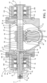
Figure 1 is a cross-sectional view of a first embodiment; -
Figure 2 is a cross-sectional view of a second embodiment; -
Figure 3 is a cross-sectional view of a third embodiment; and -
Figure 4 is a cross-sectional view of a fourth embodiment; - Referring to the Figures, wherein like numerals indicate corresponding parts throughout the several views. An electrically-powered recirculating-ball
steering gear assembly 20 for steering a vehicle includes amain housing 22 that has afirst side wall 24 and asecond side wall 26 parallel and spaced from thefirst side wall 24 along a axis A to establish achamber 28 therebetween. - The
first side wall 24 has a first worm opening 30 disposed on the axis A. Thesecond side wall 26 has a second worm opening 32 disposed on the axis A. Afirst side housing 34 is connected to thefirst side wall 24 around the first worm opening 30 in themain housing 22. Thefirst side housing 34 has aprotrusion 36 opposite the first worm opening 30. Asecond side housing 38 is connected to themain housing 22 through the second worm opening 32 and shares thesecond side wall 26 with themain housing 22. Thesecond side housing 38 has aninput wall 40 located parallel to and opposite thesecond side wall 26. Theinput wall 40 has an input opening 42 spaced opposite the second worm opening 32 along the axis A. A low friction bearing 44 is disposed in each of theworm openings protrusion 36. - A
worm shaft 46 extends along the axis A in thechamber 28 and through thelow friction bearings 44 in each of theworm openings main housing 22. Theworm shaft 46 has aworm groove 48 that extends helically to establish aworm section 50 disposed in thechamber 28. Theworm shaft 46 has afirst end section 52 that extends from theworm section 50 and into the low friction bearing 44 in the first worm opening 30 and into thefirst side housing 34. - The
worm shaft 46 has asecond end section 54 that has aworm end 56 adjacent theworm section 50 and extends from theworm end 56 and into the low friction bearing 44 in the second worm opening 32 and into thesecond side housing 38, Aball nut 58 is disposed about a portion of theworm section 50 of theworm shaft 46 and hasball raceways 60 that face theworm section 50 of theworm shaft 46 established helically within theball nut 58. A plurality ofball bearings 62 that are spherical in shape are disposed in theworm grooves 48 of theworm section 50 of theworm shaft 46 and in theball raceways 60 of theball nut 58, - A first recirculating
ball mechanism 64 is disposed within theball nut 58 to recirculate the plurality ofball bearings 62 once the plurality ofball bearings 62 rotate about theworm section 50 two and a half times. A secondrecirculating ball mechanism 66 is disposed adjacent to the first recirculatingball mechanism 64 within theball nut 58 to recirculate the plurality ofball bearings 62 once the plurality ofball bearings 62 rotate about theworm section 50 two and a half times. - An
output shaft 68 for driving a Pitman arm has an output teeth set 70 disposed radially on theoutput shaft 68. A nut teeth set 72 extends from theball nut 58 and engages the output teeth set 70 to move theball nut 58 linearly along the axis A and to rotate theoutput shaft 68 in response to the rotation of theworm shaft 46. - The
worm shaft 46 has aworm bore 74 within thesecond end section 54 of theworm shaft 46 along the axis A and closed at theworm end 56 of thesecond end section 54 of theworm shaft 46. Aninput shaft 76 responsive to rotation of a steering wheel extends from thesecond end section 54 of theworm shaft 46 along the axis A and through the low friction bearing 44 in theinput opening 42 to aninput end 78 and has aninput bore 80 within theinput shaft 76 along the axis A that is closed at theinput end 78 of theinput shaft 76. There is a lostmotion connection 82 between theinput shaft 76 and thesecond end section 54 of theworm shaft 46 that allows relative lost motion of three to four degrees between theinput shaft 76 and theworm shaft 46. Atorsion bar 84 extends axially within theinput bore 80 and the worm bore 74 and interconnects theinput shaft 76 and theworm shaft 46 for biasing against the relative lost motion and has afirst torsion end 86 and asecond torsion end 88 disposed opposite each other. Afirst pin 90 extends transversally to the axis A and connects thefirst torsion end 86 of thetorsion bar 84 to theinput end 78 of theinput shaft 76. Asecond pin 92 extends transversally to the axis A and connects thesecond torsion end 88 of thetorsion bar 84 to theworm end 56 of thesecond end section 54 of theworm shaft 46. Atorque sensor 94 is disposed about theinput shaft 76 for measuring the torque in theinput shaft 76 and communicating the torque to theelectronic control unit 96, - A
first drive system 98 is in thefirst side housing 34 to provide a steering force in response to a primary steering input. Thefirst drive system 98 includes afirst gear set 100 disposed in thefirst side housing 34 and in driving engagement with thefirst end section 52 of theworm shaft 46 and afirst motor 102 supported by thefirst side housing 34 and connected to thefirst gear set 100 and responsive to an electrical signal to rotate theworm shaft 46. - A
second drive system 104 for providing a steering force in response to a secondary steering input includes asecond motor 106 for redundantly steering the vehicle and asecond gear set 108 in driving engagement with thesecond motor 106 for receiving mechanical input from thesecond motor 106. Thesecond drive system 104 is mounted in thesecond side housing 38 and is in driving engagement with thesecond end section 54 of theworm shaft 46. Theworm section 50 of theworm shaft 46 is disposed between thefirst drive system 98 on thefirst end section 52 of theworm shaft 46 and thesecond drive system 104 on thesecond end section 54 of theworm shaft 46. Placing the drive systems in parallel allows for reduced complexity and a reduction in packaging footprint relative to placing the drive systems in series, - In
Figure 1 , thefirst gear set 100 offirst drive system 98 is aworm reducer 110 that includes aworm gear 112 and aspur gear 114. Thesecond gear set 108 of the second gear system is also aworm reducer 110 that includes aworm gear 112 and aspur gear 114. - In
Figure 2 , the first gear set 100 of thefirst drive system 98 is aplanetary gear group 116 and thefirst motor 102 is mounted coaxially with theworm shaft 46. Thesecond gear set 108 of the second gear system is also aplanetary gear group 116 and thesecond motor 106 is also mounted coaxially with theworm shaft 46. - in
Figure 3 , thefirst gear set 100 of thefirst drive system 98 is aplanetary gear group 116 and thefirst motor 102 is mounted coaxially with theworm shaft 46. Thesecond gear set 108 of the second gear system is aworm reducer 110 that includes aworm gear 112 and aspur gear 114. - In
Figure 4 , thefirst gear set 100 offirst drive system 98 is aworm reducer 110 that includes aworm gear 112 and aspur gear 114. Thesecond gear set 108 of the second gear system is aplanetary gear group 116 and thesecond motor 106 is mounted coaxially with theworm shaft 46, - An
electronic control unit 96 is electrically connected to thefirst motor 102 for responding to vehicle sensors and processors to control the amount of torque of thefirst motor 102 to apply to theworm shaft 46 to produce the required movement of theoutput shaft 68 to turn the wheels of the vehicle. - Obviously, many modifications and variations of the present invention are possible in light of the above teachings and may be practiced otherwise than as specifically described while within the scope of the appended claims. That which is prior art in the claims precedes the novelty set forth in the "characterized by" clause. The novelty is meant to be particularly and distinctly recited in the "characterized by" clause whereas the antecedent recitations merely set forth the old and well-known combination in which the invention resides. These antecedent recitations should be interpreted to cover any combination in which the inventive novelty exercises its utility. The use of the word "said" in the apparatus claims refers to an antecedent that is a positive recitation meant to be included in the coverage of the claims whereas the word "the" precedes a word not meant to be included in the coverage of the claims. In addition, the reference numerals in the claims are merely for convenience and are not to be read in any way as limiting.
Claims (4)
- An electrically-powered recirculating-ball steering gear assembly (20) for steering a vehicle, said assembly (20) comprising;a worm shaft (46) extending along an axis (A) and including a worm groove (48) extending helically to establish a worm section (50),said worm shaft (46) having a first end section (52) and a second end section (54) extending from said worm section (50),a first drive system (98) in rotatable driving engagement with said first end section (52) of said worm shaft (46) for steering the vehicle by rotating said worm shaft (46),a second drive system (104) for providing a steering force in response to a secondary steering input,said second drive system (104) being in rotatable driving engagement with said second end section (54) of said worm shaft (46) for redundantly steering the vehicle by rotating said worm shaft (46),said worm section (50) of said worm shaft (46) being disposed between said first drive system (98) disposed on said first end section (52) of said worm shaft (46) and said second drive system (104) disposed on said second end section (54) of said worm shaft (46);characterized byan input shaft (76) responsive to rotation of a steering wheel extending along said axis (A) from said second end section (54) of said worm shaft (46) ,a lost motion connection (82) between said input shaft (76) and said worm shaft (46) for allowing relative rotational lost motion between said input shaft (76) and said worm shaft (46) independent of said drive systems (98, 104);said worm shaft (46) defining a worm bore (74) extending along said axis (A) within said second end section (54) and being closed at a worm end (56) of said second end section (54),said input shaft (78) defining an input bore (80) extending along said axis (A) and being closed at an input end (78) of said input shaft (78),a torsion bar (84) extending axially within said input bore (80) and said worm bore (74) between a first torsion end (86) and a second torsion end (88), the torsion bar (84) interconnecting said input shaft (76) and said worm shaft (46) for biasing against the relative lost motion,a first pin (90) connecting said first torsion end (86) of said torsion bar (84) to said input shaft (76),a second pin (92) connecting said second torsion end (88) of said torsion bar (84) to said second end section (54) of said worm shaft (46), anda torque sensor (94) disposed about said input shaft (76) for measuring the torque in said input shaft (76) and communicating the torque to an electronic control unit (96), whereinone of said drive systems (98, 104) includes a motor (102, 106) for rotatably driving said worm shaft (46), and a worm reducer (110) including a worm gear (112) and a spur gear (114) connecting said motor (102, 106) to said worm shaft (46) for rotatably driving said worm shaft (46).
- An assembly (20) as set forth in claim 1, wherein one of said drive systems (98, 104) includes a motor (102, 106) for rotatably driving said worm shaft (46), and a planetary gear group (116) connecting said motor (102, 106) to said worm shaft (46) for rotatably driving said worm shaft (46), wherein said motor (102, 106) is mounted coaxially with said worm shaft (46).
- An assembly (20) as set forth in Claim 1, further comprising;a main housing (22) having a first side wall (24) and a second side wall (26) parallel and spaced from said first side wall (24) along said axis (A) to establish a chamber (28) therebetween,said first side wall (24) having a first worm opening (30) disposed on said axis (A),said second side wall (26) having a second worm opening (32) disposed on said axis (A),a first side housing (34) connected to said first side wall (24) around said first worm opening (30) in said main housing (22)said first side housing (34) having a protrusion (36) opposite said first worm opening (30),a second side housing (38) connected to said main housing (22) through said second worm opening (32) and sharing said second side wall (26) with said main housing (22),said second side housing (38) having an input wall (40) located parallel to and opposite said second side wall (26),said input wall (40) having an input opening (42) spaced opposite said second worm opening (32) along said axis (A),a low friction bearing (44) disposed in each of said worm openings (30, 32) and said input opening (42) and said protrusion (36),said worm shaft (46) extending in said chamber (28) and through said low friction bearings (44) in each of said worm openings (30, 32) of said main housing (22),said worm section (50) of said worm shaft (46) disposed in said chamber (28),said first end section (52) of said worm shaft (46) extending into said low friction bearing (44) in said first worm opening (30) and into said first side housing (34),said first drive system (98) disposed adjacent said first side housing (34) and including,a first gear set (100) disposed in said first side housing (34) and establishing said rotatable driving engagement with said first end section (52) of said worm shaft (46), anda first motor (102) supported by said first side housing (34) and connected to said first gear set (100) and responsive to an electrical signal for rotating said worm shaft (46),said second end section (54) of said worm shaft (46) having a worm end (56) adjacent said worm section (50) and extending from said worm end (56) and into said low friction bearing (44) in said second worm opening (32) and into said second side housing (38),a ball nut (58) disposed about a portion of said worm section (50) of said worm shaft (46) and having ball raceways (60) facing said worm section (50) of said worm shaft (46) established helically within said ball nut (58),a plurality of ball bearings (62) each spherical in shape and disposed in said worm grooves (48) of said worm section (50) of said worm shaft (46) and in said ball raceways (60) of said ball nut (58),a first recirculating ball mechanism (64) disposed within said ball nut (58) for recirculating said plurality of ball bearings (62) once said plurality of ball bearings (62) rotate about said worm section (50) two and a half times,a second recirculating ball mechanism (66) disposed adjacent to said first recirculating ball mechanism (64) within said ball nut (58) for recirculating said plurality of ball bearings (62) once said plurality of ball bearings (62) rotate about said worm section (50) two and a half times,an output shaft (68) for driving a Pitman arm having an output teeth set (70) disposed radially on said output shaft (68),a nut teeth set (72) extending from said ball nut (58) and engaging said output teeth set (70) for moving said ball nut (58) linearly along said axis (A) and to rotate said output shaft (68) in response to the rotation of said worm shaft (46),said electronic control unit (96) electrically connected to said first motor (102) for responding to vehicle sensors and processors to control the amount of torque of said first motor (102) to apply to said worm shaft (46) to produce the required movement of said output shaft (68) to turn the wheels of the vehicle,said second drive system (104) mounted adjacent said second side housing (38) and including,a second motor (106) for redundantly steering the vehicle, anda second gear set (108) in rotatable driving engagement with said second motor (106) for receiving mechanical input from said second motor (106), andsaid worm section (50) of said worm shaft (46) being disposed between said first drive system (98) disposed adjacent said first end section (52) of said worm shaft (46) and said second drive system (104) disposed adjacent said second end section (54) of said worm shaft (46).
- An assembly (20) as set forth in claim 1, wherein;
said motor (102, 106) being mounted perpendicular to both said spur gear (114) and said worm shaft (46) and in driving engagement with said worm gear (112).
Applications Claiming Priority (2)
| Application Number | Priority Date | Filing Date | Title |
|---|---|---|---|
| US201762462953P | 2017-02-24 | 2017-02-24 | |
| PCT/US2018/019698 WO2018157051A1 (en) | 2017-02-24 | 2018-02-26 | Electrically-powered recirculating-ball steering gear assembly |
Publications (3)
| Publication Number | Publication Date |
|---|---|
| EP3585673A1 EP3585673A1 (en) | 2020-01-01 |
| EP3585673B1 true EP3585673B1 (en) | 2025-05-14 |
| EP3585673C0 EP3585673C0 (en) | 2025-05-14 |
Family
ID=63246043
Family Applications (1)
| Application Number | Title | Priority Date | Filing Date |
|---|---|---|---|
| EP18710250.4A Active EP3585673B1 (en) | 2017-02-24 | 2018-02-26 | Electrically-powered recirculating-ball steering gear assembly |
Country Status (5)
| Country | Link |
|---|---|
| US (1) | US10647346B2 (en) |
| EP (1) | EP3585673B1 (en) |
| CN (1) | CN110869264A (en) |
| BR (1) | BR112019017674B1 (en) |
| WO (1) | WO2018157051A1 (en) |
Families Citing this family (30)
| Publication number | Priority date | Publication date | Assignee | Title |
|---|---|---|---|---|
| FR3071784B1 (en) * | 2017-09-29 | 2019-10-18 | Faurecia Sieges D'automobile | SCREW ADJUSTMENT MECHANISM, SLIDE COMPRISING SUCH AN ADJUSTING MECHANISM AND SEAT COMPRISING SUCH A SLIDER. |
| US11440580B2 (en) | 2018-06-01 | 2022-09-13 | Mando Corporation | Electric power steering apparatus and control method for the same, apparatus for synchronization dual steering motor and method i'hereof |
| KR102109341B1 (en) * | 2018-09-21 | 2020-05-12 | 주식회사 만도 | Electric Power Steering Apparatus for Vehicle |
| US12637135B2 (en) * | 2018-06-29 | 2026-05-26 | Hl Mando Corporation | Electronic power steering apparatus |
| KR102104456B1 (en) * | 2018-09-21 | 2020-04-24 | 주식회사 만도 | Electric Power Steering Apparatus for Vehicle |
| KR102098050B1 (en) * | 2018-09-06 | 2020-04-07 | 주식회사 만도 | Electric Power Steering Apparatus and Control Method for the same |
| KR102093853B1 (en) * | 2018-09-05 | 2020-03-26 | 주식회사 만도 | Electric Power Steering Apparatus and Control Method for the same |
| US11524717B2 (en) | 2018-09-05 | 2022-12-13 | Mando Corporation | Electric power steering apparatus and control method thereof |
| KR102106292B1 (en) * | 2018-10-05 | 2020-05-04 | 주식회사 만도 | Steer-By-Wire Type Steering Apparatus |
| DE102018127204B4 (en) * | 2018-10-31 | 2024-12-05 | Knorr-Bremse Systeme für Nutzfahrzeuge GmbH | recirculating ball steering |
| TWI822855B (en) * | 2018-11-26 | 2023-11-21 | 瑞士商Mps微精密系統股份公司 | Angle transmission device |
| KR102167914B1 (en) * | 2019-05-14 | 2020-10-20 | 주식회사 만도 | Steering Apparatus for Vehicle |
| DE102019127953B4 (en) * | 2019-10-16 | 2025-12-24 | Knorr-Bremse Systeme für Nutzfahrzeuge GmbH | Steering gear for an electromechanical steering system for a vehicle and electromechanical steering system for a vehicle |
| US11628825B2 (en) * | 2019-10-25 | 2023-04-18 | China Automotive Systems, Inc. | Method and system for compensating excessive NVH in a vehicle front suspension |
| US11345396B2 (en) * | 2020-02-18 | 2022-05-31 | Zf Active Safety And Electronics Us Llc | Modular power steering apparatus |
| US11827290B2 (en) * | 2020-11-02 | 2023-11-28 | Ford Global Technologies, Llc | Rotary assist apparatus for recirculating ball steering gears |
| US11685426B2 (en) * | 2020-11-30 | 2023-06-27 | Zf Friedrichshafen Ag | Apparatus for use in turning steerable vehicle wheels |
| US11873037B2 (en) | 2021-03-04 | 2024-01-16 | Ford Global Technologies, Llc | Belt driven rotary assist apparatus for recirculating ball steering gears |
| KR102861727B1 (en) * | 2021-03-25 | 2025-09-18 | 에이치엘만도 주식회사 | Steering apparatus and assembly method thereof |
| KR20230021931A (en) * | 2021-08-06 | 2023-02-14 | 에이치엘만도 주식회사 | Electric Power Steering Apparatus for Vehicle |
| US20230052313A1 (en) * | 2021-08-13 | 2023-02-16 | China Automotive Systems, Inc. | Electric steering assemblies for commercial vehicles |
| DE102021210741A1 (en) * | 2021-09-27 | 2023-03-30 | Robert Bosch Gesellschaft mit beschränkter Haftung | Steering gear for a steering system of a commercial vehicle |
| DE102021213063B4 (en) | 2021-11-22 | 2023-08-03 | Zf Friedrichshafen Ag | Steering drive for a steering axle of a steerable vehicle, steering axle and industrial truck |
| DE102021213067A1 (en) | 2021-11-22 | 2023-05-25 | Zf Friedrichshafen Ag | Steering drive for a steering axle of a steerable vehicle, steering axle and industrial truck |
| CN115071806B (en) * | 2022-04-17 | 2023-09-01 | 浙江世宝股份有限公司 | Screw nut assembly internal circulation structure for commercial vehicle |
| CN116279762A (en) * | 2023-01-13 | 2023-06-23 | 陕西国力信息技术有限公司 | Dual Drive Power Steering |
| US20240300570A1 (en) * | 2023-03-09 | 2024-09-12 | Ford Global Technologies, Llc | Rotary assist apparatus for recirculating ball steering gears |
| US12077219B1 (en) | 2023-06-23 | 2024-09-03 | Ford Global Technologies, Llc | Rotary steering systems |
| CN117087748A (en) * | 2023-08-22 | 2023-11-21 | 杭州世宝汽车方向机有限公司 | Electric power steering |
| US20250353543A1 (en) * | 2024-05-16 | 2025-11-20 | Zf Active Safety And Electronics Us Llc | Steering system for use in turning steerable vehicle wheels |
Citations (1)
| Publication number | Priority date | Publication date | Assignee | Title |
|---|---|---|---|---|
| US20070278031A1 (en) * | 2004-03-15 | 2007-12-06 | Per-Erik Andersson | Linear Electromechanical Actuator For A Steering System Of A Motor Vehicle |
Family Cites Families (18)
| Publication number | Priority date | Publication date | Assignee | Title |
|---|---|---|---|---|
| US2248251A (en) | 1939-04-14 | 1941-07-08 | Glenn S Reeves | Automobile steering apparatus |
| GB2151996B (en) | 1983-12-09 | 1987-04-23 | Trw Cam Gears Ltd | Power assisted steering system |
| JP2582378Y2 (en) * | 1992-02-04 | 1998-09-30 | 株式会社ユニシアジェックス | Electric power steering device |
| US6382342B1 (en) * | 2000-06-20 | 2002-05-07 | Trw Inc. | Hydraulically powered steering apparatus with electrically powered backup |
| US7014008B2 (en) * | 2002-06-27 | 2006-03-21 | Honda Giken Kogyo Kabushiki Kaisha | Steering system for vehicle |
| US6776252B1 (en) | 2003-01-24 | 2004-08-17 | Visteon Global Technologies, Inc. | Steer-by-wire system and method for actuating road wheels of a vehicle |
| JP4285310B2 (en) * | 2004-04-16 | 2009-06-24 | トヨタ自動車株式会社 | Vehicle steering device |
| CN100398373C (en) * | 2005-03-17 | 2008-07-02 | 北京理工大学 | Recirculating ball electric power steering |
| CN101054094A (en) * | 2007-05-24 | 2007-10-17 | 上海交大神舟汽车设计开发有限公司 | Steering shaft for electric boosting steering system |
| CN101700786B (en) | 2009-11-09 | 2012-08-29 | 南京航空航天大学 | Recirculating-ball electric power-assisted steering system with variable transmission ratio for bus and control method thereof |
| CN101973311B (en) * | 2010-10-13 | 2012-05-23 | 株洲易力达机电有限公司 | Integral active electric power-assisted steering mechanical structure |
| US8360197B2 (en) | 2011-03-23 | 2013-01-29 | GM Global Technology Operations LLC | Recirculating ball power steering system |
| CN102717827A (en) | 2012-07-11 | 2012-10-10 | 曾忠敏 | Active electric power-assisting circulation ball type steering system |
| US9637167B2 (en) * | 2012-10-03 | 2017-05-02 | Nissan Motor Co., Ltd. | Steering control device, and steering control method |
| DE102013219987A1 (en) * | 2013-10-02 | 2015-04-02 | Zf Lenksysteme Gmbh | Steering for a motor vehicle |
| CN203946160U (en) * | 2014-05-09 | 2014-11-19 | 安徽霍山县东湖汽车贸易有限公司 | A kind of automobile electric booster steering system |
| JP2018020743A (en) * | 2016-08-05 | 2018-02-08 | 株式会社ジェイテクト | Vehicle steering system |
| CN106379404B (en) * | 2016-10-09 | 2018-09-11 | 中国北方车辆研究所 | A kind of heavy type circulating ball type bimodulus electric power steering device |
-
2018
- 2018-02-26 CN CN201880025385.3A patent/CN110869264A/en active Pending
- 2018-02-26 BR BR112019017674-8A patent/BR112019017674B1/en active IP Right Grant
- 2018-02-26 EP EP18710250.4A patent/EP3585673B1/en active Active
- 2018-02-26 US US15/904,934 patent/US10647346B2/en active Active
- 2018-02-26 WO PCT/US2018/019698 patent/WO2018157051A1/en not_active Ceased
Patent Citations (1)
| Publication number | Priority date | Publication date | Assignee | Title |
|---|---|---|---|---|
| US20070278031A1 (en) * | 2004-03-15 | 2007-12-06 | Per-Erik Andersson | Linear Electromechanical Actuator For A Steering System Of A Motor Vehicle |
Also Published As
| Publication number | Publication date |
|---|---|
| BR112019017674A2 (en) | 2020-03-31 |
| US10647346B2 (en) | 2020-05-12 |
| EP3585673C0 (en) | 2025-05-14 |
| BR112019017674B1 (en) | 2023-10-24 |
| WO2018157051A8 (en) | 2019-09-06 |
| CN110869264A (en) | 2020-03-06 |
| US20180244305A1 (en) | 2018-08-30 |
| WO2018157051A1 (en) | 2018-08-30 |
| EP3585673A1 (en) | 2020-01-01 |
Similar Documents
| Publication | Publication Date | Title |
|---|---|---|
| US10647346B2 (en) | Electrically-powered recirculating-ball steering gear assembly | |
| US9151371B2 (en) | Ball screw device having tunnel raceway | |
| US10421481B2 (en) | Utility vehicle steering system | |
| EP2713078B1 (en) | Driven pulley made of nylon resin | |
| EP2110580B1 (en) | Ball screw mechanism and electric power steering device using the same | |
| US8960037B2 (en) | Ball screw device, linear actuator and vehicle steering system | |
| WO2018079540A1 (en) | Electric actuator | |
| US20100224436A1 (en) | Motor vehicle steering system | |
| EP3534507A1 (en) | Electric actuator | |
| US11465673B2 (en) | Motor-assisted steering ball-screw | |
| CN101258066A (en) | Steering devices and the motion conversion devices used in them | |
| US8245814B2 (en) | Transmission ratio variable mechanism and vehicle steering apparatus | |
| WO2017006106A1 (en) | A gearbox assembly for an electric power steering assembly | |
| WO2016129436A1 (en) | Rear wheel steering device | |
| US6637541B2 (en) | Steering system having an interlocking mechanism | |
| EP2308742B1 (en) | Variable transmission ratio mechanism and variable ratio steering device | |
| JP4516479B2 (en) | Rotational linear motion conversion mechanism | |
| CN113734273A (en) | Steering gear, steering system and vehicle of vehicle | |
| US20250121879A1 (en) | Rotation-limiting device and steering device | |
| US20030221897A1 (en) | Rear wheel steering device for a vehicle | |
| US7694601B2 (en) | Gear device and electric power steering apparatus | |
| KR101622510B1 (en) | Reducer having planet gear for Electric Power Steering Apparatus | |
| JP2013193565A (en) | Electric power steering device | |
| JP2012006515A (en) | Steering device for vehicle | |
| JP2004175239A (en) | Transmission device and electric power steering device equipped therewith |
Legal Events
| Date | Code | Title | Description |
|---|---|---|---|
| STAA | Information on the status of an ep patent application or granted ep patent |
Free format text: STATUS: UNKNOWN |
|
| STAA | Information on the status of an ep patent application or granted ep patent |
Free format text: STATUS: THE INTERNATIONAL PUBLICATION HAS BEEN MADE |
|
| PUAI | Public reference made under article 153(3) epc to a published international application that has entered the european phase |
Free format text: ORIGINAL CODE: 0009012 |
|
| STAA | Information on the status of an ep patent application or granted ep patent |
Free format text: STATUS: REQUEST FOR EXAMINATION WAS MADE |
|
| 17P | Request for examination filed |
Effective date: 20190814 |
|
| AK | Designated contracting states |
Kind code of ref document: A1 Designated state(s): AL AT BE BG CH CY CZ DE DK EE ES FI FR GB GR HR HU IE IS IT LI LT LU LV MC MK MT NL NO PL PT RO RS SE SI SK SM TR |
|
| AX | Request for extension of the european patent |
Extension state: BA ME |
|
| DAV | Request for validation of the european patent (deleted) | ||
| DAX | Request for extension of the european patent (deleted) | ||
| STAA | Information on the status of an ep patent application or granted ep patent |
Free format text: STATUS: EXAMINATION IS IN PROGRESS |
|
| 17Q | First examination report despatched |
Effective date: 20200907 |
|
| GRAP | Despatch of communication of intention to grant a patent |
Free format text: ORIGINAL CODE: EPIDOSNIGR1 |
|
| STAA | Information on the status of an ep patent application or granted ep patent |
Free format text: STATUS: GRANT OF PATENT IS INTENDED |
|
| INTG | Intention to grant announced |
Effective date: 20250207 |
|
| GRAS | Grant fee paid |
Free format text: ORIGINAL CODE: EPIDOSNIGR3 |
|
| GRAA | (expected) grant |
Free format text: ORIGINAL CODE: 0009210 |
|
| STAA | Information on the status of an ep patent application or granted ep patent |
Free format text: STATUS: THE PATENT HAS BEEN GRANTED |
|
| AK | Designated contracting states |
Kind code of ref document: B1 Designated state(s): AL AT BE BG CH CY CZ DE DK EE ES FI FR GB GR HR HU IE IS IT LI LT LU LV MC MK MT NL NO PL PT RO RS SE SI SK SM TR |
|
| REG | Reference to a national code |
Ref country code: GB Ref legal event code: FG4D |
|
| REG | Reference to a national code |
Ref country code: CH Ref legal event code: EP |
|
| REG | Reference to a national code |
Ref country code: IE Ref legal event code: FG4D |
|
| U01 | Request for unitary effect filed |
Effective date: 20250514 |
|
| U07 | Unitary effect registered |
Designated state(s): AT BE BG DE DK EE FI FR IT LT LU LV MT NL PT RO SE SI Effective date: 20250520 |
|
| PG25 | Lapsed in a contracting state [announced via postgrant information from national office to epo] |
Ref country code: ES Free format text: LAPSE BECAUSE OF FAILURE TO SUBMIT A TRANSLATION OF THE DESCRIPTION OR TO PAY THE FEE WITHIN THE PRESCRIBED TIME-LIMIT Effective date: 20250514 |
|
| PG25 | Lapsed in a contracting state [announced via postgrant information from national office to epo] |
Ref country code: GR Free format text: LAPSE BECAUSE OF FAILURE TO SUBMIT A TRANSLATION OF THE DESCRIPTION OR TO PAY THE FEE WITHIN THE PRESCRIBED TIME-LIMIT Effective date: 20250815 Ref country code: NO Free format text: LAPSE BECAUSE OF FAILURE TO SUBMIT A TRANSLATION OF THE DESCRIPTION OR TO PAY THE FEE WITHIN THE PRESCRIBED TIME-LIMIT Effective date: 20250814 |
|
| PG25 | Lapsed in a contracting state [announced via postgrant information from national office to epo] |
Ref country code: PL Free format text: LAPSE BECAUSE OF FAILURE TO SUBMIT A TRANSLATION OF THE DESCRIPTION OR TO PAY THE FEE WITHIN THE PRESCRIBED TIME-LIMIT Effective date: 20250514 |
|
| PG25 | Lapsed in a contracting state [announced via postgrant information from national office to epo] |
Ref country code: HR Free format text: LAPSE BECAUSE OF FAILURE TO SUBMIT A TRANSLATION OF THE DESCRIPTION OR TO PAY THE FEE WITHIN THE PRESCRIBED TIME-LIMIT Effective date: 20250514 |
|
| PG25 | Lapsed in a contracting state [announced via postgrant information from national office to epo] |
Ref country code: RS Free format text: LAPSE BECAUSE OF FAILURE TO SUBMIT A TRANSLATION OF THE DESCRIPTION OR TO PAY THE FEE WITHIN THE PRESCRIBED TIME-LIMIT Effective date: 20250814 |
|
| PG25 | Lapsed in a contracting state [announced via postgrant information from national office to epo] |
Ref country code: IS Free format text: LAPSE BECAUSE OF FAILURE TO SUBMIT A TRANSLATION OF THE DESCRIPTION OR TO PAY THE FEE WITHIN THE PRESCRIBED TIME-LIMIT Effective date: 20250914 |
|
| PG25 | Lapsed in a contracting state [announced via postgrant information from national office to epo] |
Ref country code: SM Free format text: LAPSE BECAUSE OF FAILURE TO SUBMIT A TRANSLATION OF THE DESCRIPTION OR TO PAY THE FEE WITHIN THE PRESCRIBED TIME-LIMIT Effective date: 20250514 |
|
| PG25 | Lapsed in a contracting state [announced via postgrant information from national office to epo] |
Ref country code: CZ Free format text: LAPSE BECAUSE OF FAILURE TO SUBMIT A TRANSLATION OF THE DESCRIPTION OR TO PAY THE FEE WITHIN THE PRESCRIBED TIME-LIMIT Effective date: 20250514 |
|
| PG25 | Lapsed in a contracting state [announced via postgrant information from national office to epo] |
Ref country code: SK Free format text: LAPSE BECAUSE OF FAILURE TO SUBMIT A TRANSLATION OF THE DESCRIPTION OR TO PAY THE FEE WITHIN THE PRESCRIBED TIME-LIMIT Effective date: 20250514 |
|
| PLBE | No opposition filed within time limit |
Free format text: ORIGINAL CODE: 0009261 |
|
| STAA | Information on the status of an ep patent application or granted ep patent |
Free format text: STATUS: NO OPPOSITION FILED WITHIN TIME LIMIT |
|
| REG | Reference to a national code |
Ref country code: CH Ref legal event code: L10 Free format text: ST27 STATUS EVENT CODE: U-0-0-L10-L00 (AS PROVIDED BY THE NATIONAL OFFICE) Effective date: 20260325 |
|
| U20 | Renewal fee for the european patent with unitary effect paid |
Year of fee payment: 9 Effective date: 20260227 |
|
| PGFP | Annual fee paid to national office [announced via postgrant information from national office to epo] |
Ref country code: GB Payment date: 20260227 Year of fee payment: 9 |
|
| 26N | No opposition filed |
Effective date: 20260217 |