CN100398373C - Recirculating ball electric power steering - Google Patents
Recirculating ball electric power steering Download PDFInfo
- Publication number
- CN100398373C CN100398373C CNB2005100552474A CN200510055247A CN100398373C CN 100398373 C CN100398373 C CN 100398373C CN B2005100552474 A CNB2005100552474 A CN B2005100552474A CN 200510055247 A CN200510055247 A CN 200510055247A CN 100398373 C CN100398373 C CN 100398373C
- Authority
- CN
- China
- Prior art keywords
- gear
- steering
- worm
- motor
- assisted
- Prior art date
- Legal status (The legal status is an assumption and is not a legal conclusion. Google has not performed a legal analysis and makes no representation as to the accuracy of the status listed.)
- Expired - Lifetime
Links
Images


Landscapes
- Power Steering Mechanism (AREA)
Abstract
一种循环球式电动助力转向器,除了包括螺杆、螺母、齿扇、钢球等机械零件外,还包括转矩传感装置、助力电动机、减速机构、电子控制单元等。电子控制单元根据转向盘转矩与车速确定电动机的目标电流,然后对电动机电流进行反馈跟踪控制。减速机构输入端与电动机连接,减速机构输出端与循环球转向器中的螺杆或齿扇轴连接。本发明可节约能量、在各种行驶工况下提供合适的助力、零件少、质量轻、结构紧凑、装配自动化程度高,是一种节能、安全、环保的车辆动力转向器。
A recirculating ball type electric power steering device, in addition to mechanical parts such as a screw, a nut, a gear fan, and a steel ball, also includes a torque sensing device, a power assist motor, a speed reduction mechanism, an electronic control unit, and the like. The electronic control unit determines the target current of the motor according to the torque of the steering wheel and the vehicle speed, and then performs feedback tracking control on the motor current. The input end of the reduction mechanism is connected with the electric motor, and the output end of the reduction mechanism is connected with the screw rod or the gear fan shaft in the recirculating ball steering gear. The invention can save energy, provide proper power assist under various driving conditions, has few parts, light weight, compact structure and high degree of assembly automation, and is an energy-saving, safe and environment-friendly vehicle power steering gear.
Description
所属技术领域Technical field
本发明属汽车部件技术领域,具体涉及一种车辆用循环球式电动助力转向器。The invention belongs to the technical field of automobile parts, and in particular relates to a recirculating ball type electric power steering device for vehicles.
背景技术 Background technique
目前车辆用转向器主要分齿轮齿条式和循环球式两种。常用的动力转向为液压动力转向,助力大小通过滑阀或转阀加以控制。传统液压动力转向存在以下问题:在选定参数完成设计后,助力特性也就确定了,不能进行调节与控制,不仅转向盘回正能力差,而且难以协调低速转向轻便性与高速转向“路感”的矛盾;存在能量损失,即使不转向,油泵也一直工作,增加了能量消耗;由于液压系统本身存在漏油与维护问题,提高了维修成本,而液压油还会对环境造成污染。油泵、皮带轮、液压管路等元件占用空间,不好布置;低温工作性能较差。At present, the steering gear for vehicles is mainly divided into two types: rack and pinion type and recirculating ball type. The commonly used power steering is hydraulic power steering, and the power assist is controlled by a slide valve or a rotary valve. The traditional hydraulic power steering has the following problems: After the design of the selected parameters is completed, the power assist characteristics are determined, and adjustment and control cannot be performed. "; there is energy loss, even if there is no steering, the oil pump keeps working, which increases energy consumption; due to oil leakage and maintenance problems in the hydraulic system itself, the maintenance cost is increased, and the hydraulic oil will also pollute the environment. Components such as oil pumps, pulleys, and hydraulic pipelines take up space and are difficult to arrange; low-temperature performance is poor.
电动助力转向系统直接由电动机提供助力,取消了液压系统,系统由转向盘转矩传感器、车速传感器、控制器、助力电动机及减速机构等组成。基本原理是控制器接受转向盘转矩信号和车速信号,经过判断和处理后,根据事先确定好的助力特性输出控制信号,控制电动机输出助力扭矩。电动助力转向系统能很好的克服液压动力转向存在的问题,具有节能,提高安全性,有利于环保等许多优点,有逐步取代液压动力转向的趋势,是未来动力转向技术的发展方向之一。但是目前世界范围内的电动助力转向系统还只是应用在轿车上,且都为齿轮齿条式转向器。The electric power steering system is directly assisted by the electric motor, and the hydraulic system is canceled. The system is composed of a steering wheel torque sensor, a vehicle speed sensor, a controller, a power assist motor, and a reduction mechanism. The basic principle is that the controller receives the steering wheel torque signal and the vehicle speed signal, and after judgment and processing, outputs a control signal according to the pre-determined power boost characteristics, and controls the motor to output power boost torque. The electric power steering system can well overcome the existing problems of hydraulic power steering. It has many advantages such as energy saving, safety improvement, and environmental protection. It has a tendency to gradually replace hydraulic power steering and is one of the development directions of power steering technology in the future. But at present, the electric power steering system in the world is only applied on the car, and all of them are rack and pinion steering gears.
发明内容 Contents of the invention
本发明的目的在于提供一种高效节能、低速转向轻便、高速转向路感强、以及回正能力好的循环球式电动助力转向器。The object of the present invention is to provide a recirculating ball electric power steering device with high efficiency and energy saving, light steering at low speed, strong road feeling at high speed steering, and good centering ability.
本发明的上述目的是通过这样的技术方案实现的,即一种循环球式电动助力转向器,除了包括螺杆、螺母、齿扇、循环钢球等机械零件外,还包括:The above object of the present invention is achieved through such a technical solution, that is, a recirculating ball electric power steering, in addition to mechanical parts such as screw, nut, gear fan, circulating steel ball, also includes:
(一)助力电动机,用于提供辅助转向力矩;(1) A booster motor, used to provide auxiliary steering torque;
(二)减速机构,输入端与助力电动机联接,起降速增扭的作用;(2) The deceleration mechanism, the input end is connected with the booster motor, which plays the role of reducing speed and increasing torque;
(三)转矩传感装置,用于检测作用在转向盘上的力矩;(3) Torque sensing device, used to detect the torque acting on the steering wheel;
(四)电子控制单元,用于根据采集到的转向盘转矩、车速等信号,控制助力电动机电流。(4) The electronic control unit is used to control the current of the booster motor according to the collected signals such as steering wheel torque and vehicle speed.
所述减速机构的输入端与助力电动机连接,根据助力位置的不同,输出端与循环球转向器中的螺杆或齿扇轴连接。具体结构可以为蜗轮蜗杆机构或行星齿轮机构。对蜗轮蜗杆机构,蜗杆可以带动蜗轮转动,蜗轮也可以带动蜗杆转动,蜗轮蜗杆的传动是可逆的;蜗杆与助力电动机连接,蜗轮与螺杆或齿扇轴连接;另外从蜗杆强度考虑,蜗杆应设计成双头。对行星齿轮机构,行星轮支架与助力电动机连接,太阳轮与螺杆或齿扇轴连接,齿圈在壳体上。The input end of the reduction mechanism is connected with the booster motor, and the output end is connected with the screw or the fan shaft in the recirculating ball steering gear according to the position of the booster. The specific structure can be a worm gear mechanism or a planetary gear mechanism. For the worm gear mechanism, the worm can drive the worm gear to rotate, and the worm gear can also drive the worm to rotate. The transmission of the worm gear is reversible; the worm is connected to the booster motor, and the worm gear is connected to the screw or the gear fan shaft; in addition, considering the strength of the worm, the worm should be designed into double heads. For the planetary gear mechanism, the planetary gear bracket is connected with the booster motor, the sun gear is connected with the screw or the gear fan shaft, and the ring gear is on the housing.
所述转矩传感装置中设有一扭杆,通过一套精密的机械装置,将扭杆的变形放大成角位移或线位移,由角位移或线位移传感器间接测得扭杆的变形,根据扭杆刚度即可得转矩。A torsion bar is provided in the torque sensing device, and the deformation of the torsion bar is amplified into angular displacement or linear displacement through a set of precise mechanical devices, and the deformation of the torsion bar is indirectly measured by the angular displacement or linear displacement sensor, according to The torque is obtained by the stiffness of the torsion bar.
所述电子控制单元主要由CPU、信号采集与处理电路、驱动电路、监测电路等组成。其中CPU为8位或16位单片机,也可以为16位数字信号处理器。电动机驱动电路中设置有电子开关,当系统出现异常后,迅速切断开关,以保证系统安全。The electronic control unit is mainly composed of a CPU, a signal acquisition and processing circuit, a driving circuit, a monitoring circuit and the like. Wherein the CPU is an 8-bit or 16-bit microcontroller, or a 16-bit digital signal processor. There is an electronic switch in the motor drive circuit, and when the system is abnormal, the switch will be cut off quickly to ensure the safety of the system.
本发明的有益效果是,只在转向时电动机才提供助力,不像液压动力转向,即使在不转向时,油泵也一直运转,因而能减少能量消耗;能在各种行驶工况下提供合适的助力,减小由路面不平所引起的对转向系统的扰动,改善汽车的转向特性,减轻汽车低速行驶时的转向操纵力,提高汽车高速行驶时的转向稳定性,进而提高汽车的主动安全性,且可通过设置不同的转向手力特性来满足不同使用对象的需要;取消了油泵、皮带、皮带轮、液压软管、液压油及密封件等,其零件比液压动力转向大大减少,因而其质量更轻、结构更紧凑,在安装位置选择方面也更容易,并且能降低噪声;没有液压回路,比液压动力转向更易调整和检测,装配自动化程度更高,并且可以通过设置不同的程序,能快速与不同车型匹配,因而能缩短生产和开发周期;不存在渗油问题,可大大降低保修成本,减小对环境的污染;比液压动力转向具有更好的低温工作性能。The beneficial effect of the present invention is that the electric motor provides power assist only when turning, unlike hydraulic power steering, the oil pump runs all the time even when not turning, thereby reducing energy consumption; Power assist, reduce the disturbance to the steering system caused by uneven road surface, improve the steering characteristics of the car, reduce the steering force when the car is running at low speed, improve the steering stability of the car when driving at high speed, and then improve the active safety of the car. And it can meet the needs of different users by setting different steering hand force characteristics; canceling oil pumps, belts, pulleys, hydraulic hoses, hydraulic oil and seals, etc., its parts are greatly reduced compared with hydraulic power steering, so its quality is higher Lighter, more compact structure, easier to choose the installation location, and can reduce noise; no hydraulic circuit, easier to adjust and detect than hydraulic power steering, higher degree of assembly automation, and can be quickly integrated with Different models are matched, so the production and development cycle can be shortened; there is no oil leakage problem, which can greatly reduce maintenance costs and reduce environmental pollution; it has better low-temperature performance than hydraulic power steering.
附图说明 Description of drawings
本发明的上述结构可以通过附图和实施例作进一步说明。The above structure of the present invention can be further illustrated by the accompanying drawings and embodiments.
图1是本发明的控制原理图。Fig. 1 is the control schematic diagram of the present invention.
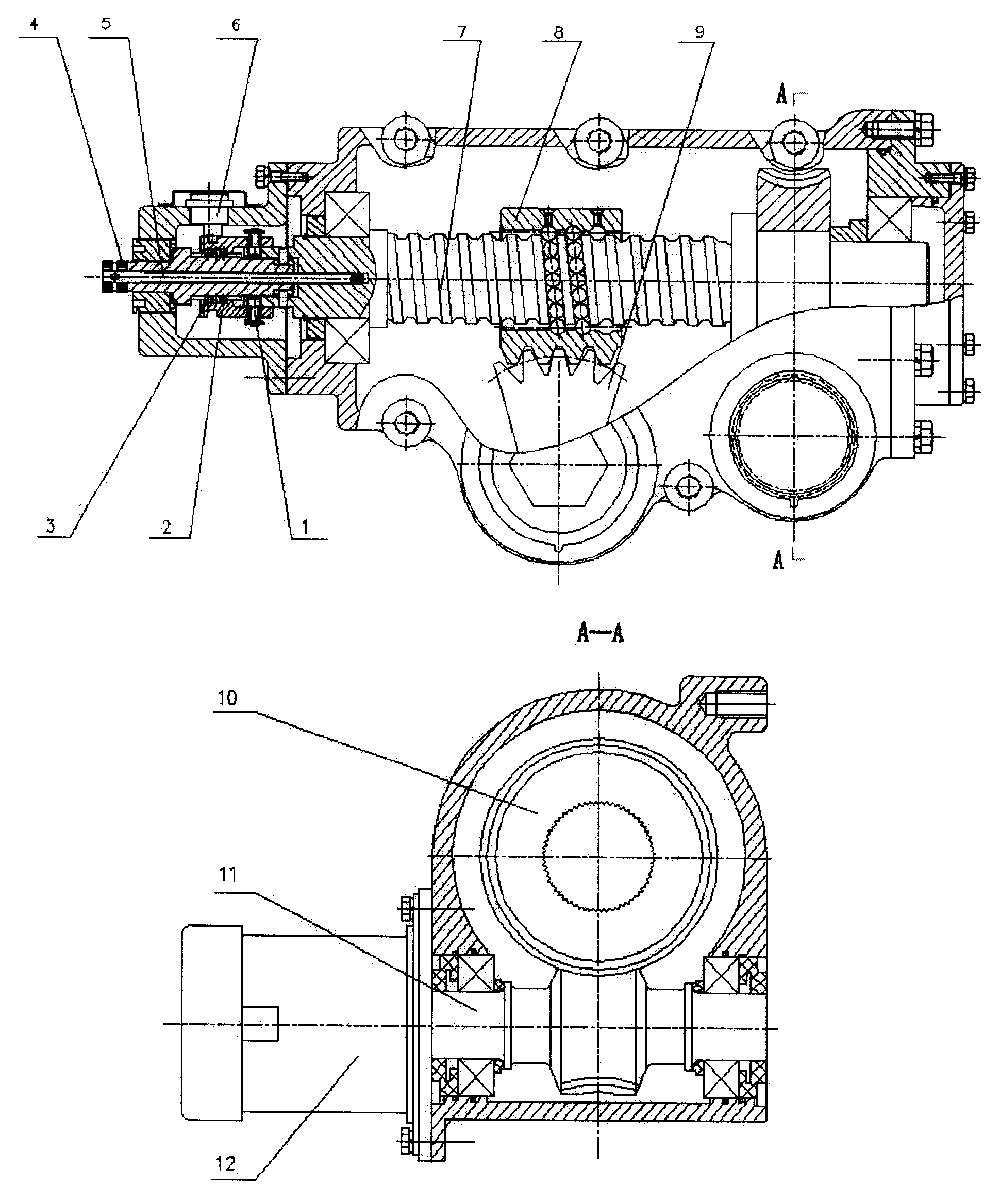
图2是本发明采用蜗轮蜗杆减速机构且布置在螺杆上的机械结构图。Fig. 2 is a mechanical structure diagram of the present invention adopting a worm gear reduction mechanism arranged on a screw.
图3是本发明采用蜗轮蜗杆减速机构且布置在齿扇轴上的机械结构图。Fig. 3 is a mechanical structure diagram of the present invention adopting a worm gear reduction mechanism and arranged on the gear fan shaft.
图4是本发明采用行星齿轮减速机构且布置在螺杆上的机械结构图。Fig. 4 is a mechanical structure diagram of the present invention adopting a planetary gear reduction mechanism arranged on a screw.
图5是本发明采用直流永磁有刷电动机的电子控制单元原理图。Fig. 5 is a schematic diagram of an electronic control unit using a DC permanent magnet brushed motor in the present invention.
上述图2中,1为传动销;2为滑套;3为钢球;4为转向器输入轴;5为扭杆;6为角位移传感器;7为螺杆;8为螺母;9为齿扇;10为蜗轮;11为蜗杆;12为助力电动机。In the above Figure 2, 1 is the transmission pin; 2 is the sliding sleeve; 3 is the steel ball; 4 is the input shaft of the steering gear; 5 is the torsion bar; 6 is the angular displacement sensor; 7 is the screw; 8 is the nut; ; 10 is a worm gear; 11 is a worm; 12 is a booster motor.
上述图3中,1为传动销;2为滑套;3为钢球;4为转向器输入轴;5为扭杆;6为角位移传感器;7为螺杆;8为螺母;9为齿扇;10为蜗轮;11为蜗杆;12为助力电动机;13为齿扇轴。In the above Figure 3, 1 is the transmission pin; 2 is the sliding sleeve; 3 is the steel ball; 4 is the input shaft of the steering gear; 5 is the torsion bar; 6 is the angular displacement sensor; 7 is the screw; 8 is the nut; ; 10 is a worm gear; 11 is a worm; 12 is a booster motor; 13 is a fan shaft.
上述图4中,1为传动销;2为滑套;3为钢球;4为转向器输入轴;5为扭杆;6为角位移传感器;7为螺杆;8为螺母;9为齿扇;10为行星轮;11为太阳轮;12为助力电动机;13为行星轮托架。In the above Figure 4, 1 is the transmission pin; 2 is the sliding sleeve; 3 is the steel ball; 4 is the steering gear input shaft; 5 is the torsion bar; 6 is the angular displacement sensor; 7 is the screw; 8 is the nut; 9 is the gear sector ; 10 is a planetary gear; 11 is a sun gear; 12 is a booster motor; 13 is a planetary wheel bracket.
具体实施方式 Detailed ways
如图1所示,电子控制单元根据采集到的转向盘转矩Ts与车速V确定助力电动机的目标电流Icmd,然后根据助力电动机的实际电流I与目标电流Icmd对助力电动机电流进行反馈跟踪控制。As shown in Figure 1, the electronic control unit determines the target current Icmd of the booster motor according to the collected steering wheel torque Ts and vehicle speed V, and then performs feedback tracking control on the booster motor current according to the actual current I and target current Icmd of the booster motor .
如图2所示,扭杆5的一端与转向器输入端4连接,另一端与螺杆7过盈配合刚性连接,扭杆5的扭转变形通过钢球3传递给滑套2,传动销1与螺杆7刚性连接,并通过与滑套2上的螺旋槽配合,在滑套2转动的同时,产生轴向移动,通过角位移传感器6测量滑套2的轴向移动量,将扭杆5的相对变形,即转向器输入端4与螺杆7的相对转角,转换为表示转矩的电信号输入给电子控制单元。螺杆7与螺母8构成循环球传动副。螺母8上的齿条与齿扇轴上的齿扇9相啮合,将转向力矩输出。蜗轮10通过花键与螺杆7连接。电动机12的输出轴与蜗杆11通过花键连接,经过蜗轮10与蜗杆11组成的蜗轮蜗杆减速机构将电动机输出的转向力矩传递到螺杆7上。As shown in Figure 2, one end of the
如图3所示,蜗轮10通过键与齿扇轴13(即:摇臂轴)连接,电动机12的输出轴与蜗杆11通过花键连接,经过蜗轮10与蜗杆11组成的减速机构将电动机输出的转向力矩传递到齿扇轴13上。As shown in Figure 3, the
如图4所示,电动机12的输出轴与行星托架13通过花键连接,经过太阳轮11、行星轮10及行星轮托架13组成的行星齿轮减速机构将助力电动机输出的转向力矩传递到螺杆7上。其中太阳轮11通过花键与螺杆7连接。As shown in Figure 4, the output shaft of the
如图5所示,电子控制单元主要由CPU、信号采集与处理电路、驱动电路、监测电路等组成。CPU为8位或16位单片机,也可以为16位数字信号处理器(DSP)。信号采集与处理电路用于采集电动机电流信号,以及处理转矩信号、车速信号、发动机转速信号等。驱动电路包括电子开关(如继电器)、状态指示灯和电动机的驱动。其中电动机的驱动是一个H型PWM功率转换电路,由MOSFET管G1、G2、G3、G4组成。MOSFET管的开关由PWM信号的高低电平控制,PWM信号的频率为20kHz。电动机驱动电路中还设置有电子开关(如继电器),当系统出现异常后,迅速切断开关,以保证系统安全。监测电路用于对系统进行保护,提高系统的安全可靠性。As shown in Figure 5, the electronic control unit is mainly composed of CPU, signal acquisition and processing circuit, driving circuit, monitoring circuit and so on. The CPU is an 8-bit or 16-bit microcontroller, or a 16-bit digital signal processor (DSP). The signal acquisition and processing circuit is used to collect motor current signals, and process torque signals, vehicle speed signals, engine speed signals, etc. The driving circuit includes the driving of electronic switches (such as relays), status indicators and motors. The drive of the motor is an H-type PWM power conversion circuit, which is composed of MOSFET tubes G 1 , G 2 , G 3 , and G 4 . The switching of the MOSFET tube is controlled by the high and low levels of the PWM signal, and the frequency of the PWM signal is 20kHz. An electronic switch (such as a relay) is also provided in the motor drive circuit. When the system is abnormal, the switch is cut off quickly to ensure the safety of the system. The monitoring circuit is used to protect the system and improve the safety and reliability of the system.
Claims (1)
Priority Applications (1)
| Application Number | Priority Date | Filing Date | Title |
|---|---|---|---|
| CNB2005100552474A CN100398373C (en) | 2005-03-17 | 2005-03-17 | Recirculating ball electric power steering |
Applications Claiming Priority (1)
| Application Number | Priority Date | Filing Date | Title |
|---|---|---|---|
| CNB2005100552474A CN100398373C (en) | 2005-03-17 | 2005-03-17 | Recirculating ball electric power steering |
Publications (2)
| Publication Number | Publication Date |
|---|---|
| CN1647984A CN1647984A (en) | 2005-08-03 |
| CN100398373C true CN100398373C (en) | 2008-07-02 |
Family
ID=34876741
Family Applications (1)
| Application Number | Title | Priority Date | Filing Date |
|---|---|---|---|
| CNB2005100552474A Expired - Lifetime CN100398373C (en) | 2005-03-17 | 2005-03-17 | Recirculating ball electric power steering |
Country Status (1)
| Country | Link |
|---|---|
| CN (1) | CN100398373C (en) |
Families Citing this family (25)
| Publication number | Priority date | Publication date | Assignee | Title |
|---|---|---|---|---|
| CN102123902A (en) * | 2009-10-30 | 2011-07-13 | 日本精工株式会社 | Electric power steering device |
| DE102011003562A1 (en) * | 2011-02-03 | 2012-08-09 | Ford Global Technologies, Llc | Ball screw and thus equipped steering device |
| US8567554B2 (en) * | 2011-03-23 | 2013-10-29 | GM Global Technology Operations LLC | Recirculating ball power steering system |
| US8360197B2 (en) * | 2011-03-23 | 2013-01-29 | GM Global Technology Operations LLC | Recirculating ball power steering system |
| US20130032430A1 (en) * | 2011-08-04 | 2013-02-07 | GM Global Technology Operations LLC | Electrically-assisted parallelogram power steering system |
| CN103192869A (en) * | 2012-01-09 | 2013-07-10 | 江苏罡阳动力转向器厂 | Recirculating ball electric power steering device with self-diagnosis function |
| CN103072619B (en) * | 2012-01-15 | 2015-04-29 | 山东交通学院 | Connecting device of steering gear plumbing arm |
| CN102673637A (en) * | 2012-05-10 | 2012-09-19 | 清华大学 | Electric power-assisted steering system for commercial vehicle |
| CN102717827A (en) * | 2012-07-11 | 2012-10-10 | 曾忠敏 | Active electric power-assisting circulation ball type steering system |
| JP5982313B2 (en) * | 2013-03-25 | 2016-08-31 | 日立オートモティブシステムズ株式会社 | Power steering device and power steering reduction device |
| US9180905B2 (en) * | 2013-05-30 | 2015-11-10 | Mando Corporation | Electric power steering apparatus for vehicle |
| US9193378B2 (en) * | 2013-05-30 | 2015-11-24 | Mando Corporation | Electric power steering apparatus for vehicle |
| CN103921840A (en) * | 2014-05-03 | 2014-07-16 | 顾志强 | Double-input-end ball-nut type steering gear |
| DE102015217045A1 (en) * | 2015-09-07 | 2017-03-09 | Volkswagen Aktiengesellschaft | Commercial vehicle steering |
| CN105564498A (en) * | 2016-02-05 | 2016-05-11 | 江门市兴江转向器有限公司 | Automotive circulating ball type electric steering gear |
| CN110282006B (en) * | 2016-10-09 | 2020-08-18 | 中国北方车辆研究所 | A manual mode of an electric power steering device |
| US10647346B2 (en) * | 2017-02-24 | 2020-05-12 | China Automotive Systems, Inc | Electrically-powered recirculating-ball steering gear assembly |
| CN107453536B (en) * | 2017-08-24 | 2019-11-29 | 北京动力机械研究所 | High efficiency motor mechanism transmission mechanism |
| CN108715185A (en) * | 2018-04-28 | 2018-10-30 | 人马(江苏)智能科技有限公司 | A kind of commercial car line traffic control electric boosting steering system |
| CN111907589A (en) * | 2020-08-13 | 2020-11-10 | 沙市久隆汽车动力转向器有限公司 | Heavy truck intelligent hybrid power steering gear with electronic locking function |
| CN112026915B (en) * | 2020-09-23 | 2021-10-26 | 杭州世宝汽车方向机有限公司 | Electric power steering apparatus and torque transmission mechanism thereof |
| CN112061230A (en) * | 2020-09-23 | 2020-12-11 | 杭州世宝汽车方向机有限公司 | Electric power steering device and its torque transmission device |
| CN112061232A (en) * | 2020-09-29 | 2020-12-11 | 西安电子科技大学芜湖研究院 | Intelligent electric power-assisted steering system of commercial vehicle |
| CN215284964U (en) * | 2021-03-11 | 2021-12-24 | 绵阳师范学院 | Large-output-torque electric power steering gear |
| CN114278711A (en) * | 2021-12-20 | 2022-04-05 | 湖北恒隆汽车系统集团有限公司 | A cylindrical gear and planetary gear combined electric power-assisted recirculating ball steering gear |
Citations (6)
| Publication number | Priority date | Publication date | Assignee | Title |
|---|---|---|---|---|
| CN85100100A (en) * | 1985-04-01 | 1985-09-10 | 清华大学 | Automobile gear ratio recirculating ball steering gear |
| CN2098423U (en) * | 1991-05-16 | 1992-03-11 | 清华大学 | Automobile recirculating ball - guide groove steering gear |
| US5271474A (en) * | 1992-02-04 | 1993-12-21 | Koyo SeikoCo., Ltd. | Electric power steering apparatus |
| CN2633702Y (en) * | 2003-06-10 | 2004-08-18 | 李振全 | Electric booster turning mechanism for vehicle |
| US20040210366A1 (en) * | 2003-04-16 | 2004-10-21 | Toyoda Koki Kabushiki Kaisha | Steering angle detection device for electric power steering apparatus |
| CN2685190Y (en) * | 2003-12-26 | 2005-03-16 | 毕大宁 | Integral circulating ball type electric steering device |
-
2005
- 2005-03-17 CN CNB2005100552474A patent/CN100398373C/en not_active Expired - Lifetime
Patent Citations (6)
| Publication number | Priority date | Publication date | Assignee | Title |
|---|---|---|---|---|
| CN85100100A (en) * | 1985-04-01 | 1985-09-10 | 清华大学 | Automobile gear ratio recirculating ball steering gear |
| CN2098423U (en) * | 1991-05-16 | 1992-03-11 | 清华大学 | Automobile recirculating ball - guide groove steering gear |
| US5271474A (en) * | 1992-02-04 | 1993-12-21 | Koyo SeikoCo., Ltd. | Electric power steering apparatus |
| US20040210366A1 (en) * | 2003-04-16 | 2004-10-21 | Toyoda Koki Kabushiki Kaisha | Steering angle detection device for electric power steering apparatus |
| CN2633702Y (en) * | 2003-06-10 | 2004-08-18 | 李振全 | Electric booster turning mechanism for vehicle |
| CN2685190Y (en) * | 2003-12-26 | 2005-03-16 | 毕大宁 | Integral circulating ball type electric steering device |
Also Published As
| Publication number | Publication date |
|---|---|
| CN1647984A (en) | 2005-08-03 |
Similar Documents
| Publication | Publication Date | Title |
|---|---|---|
| CN100398373C (en) | Recirculating ball electric power steering | |
| CN101450677A (en) | Motor push rod type power-assisted steering apparatus | |
| CN202294949U (en) | Electric power steering system of off-highway vehicle | |
| CN103359161B (en) | Vehicle line traffic control steering direction dish device | |
| CN113335371B (en) | A commercial vehicle multifunctional electric recirculating ball steering system and control method thereof | |
| CN105235738A (en) | Dual-motor synchronous-driving steering actuator of automobile steer-by-wire system | |
| CN102673637A (en) | Electric power-assisted steering system for commercial vehicle | |
| CN216185449U (en) | A drive-by-wire a steering system for heavy commercial car | |
| CN112249152B (en) | Electric power steering system of large commercial vehicle and control method thereof | |
| CN102632921B (en) | Electric drive pusher type steering system controlled by coupling force and displacement and control method | |
| CN111284556A (en) | Circulating ball type electric power steering gear | |
| CN111776064A (en) | An electric recirculating ball steering gear assembly for medium truck commercial vehicles | |
| CN113815721A (en) | A steering-by-wire system for heavy commercial vehicles | |
| CN205131349U (en) | Two synchronous motors drive of car drive -by -wire a steering system turns to actuating mechanism | |
| CN205327155U (en) | Electronic steering gear of circulation ball formula | |
| CN206520647U (en) | Electric automobile electric power-assisted steering apparatus | |
| CN202243633U (en) | Electric steering device with automatic aligning function for automobile | |
| CN103158754A (en) | Vehicle steering wheel limit device | |
| CN115140160A (en) | Electric drive steering system suitable for fork truck uses | |
| CN112499525B (en) | Electric counterweight type forklift and electric power steering system thereof | |
| CN213771215U (en) | Electric counterbalanced forklift and its electric power steering system | |
| CN201086737Y (en) | Automobile Steering Servo Control System | |
| CN112249153B (en) | Electric power steering device for large-scale commercial vehicle drive-by-wire chassis | |
| CN205256423U (en) | Electrical power assisted steering system | |
| CN213921204U (en) | Electric power steering device for wire-controlled chassis of large-scale commercial vehicle |
Legal Events
| Date | Code | Title | Description |
|---|---|---|---|
| C06 | Publication | ||
| PB01 | Publication | ||
| C10 | Entry into substantive examination | ||
| SE01 | Entry into force of request for substantive examination | ||
| C14 | Grant of patent or utility model | ||
| GR01 | Patent grant | ||
| C41 | Transfer of patent application or patent right or utility model | ||
| TR01 | Transfer of patent right |
Effective date of registration: 20170220 Address after: 102300 Beijing City, Mentougou District, West Lake Stone Lake Road, building 98, No. 8 Patentee after: BEIJING AUTONICS TECHNOLOGY Co.,Ltd. Address before: 100081 No. 5, Zhongguancun South Street, Haidian District, Beijing Patentee before: BEIJING INSTITUTE OF TECHNOLOGY |
|
| CX01 | Expiry of patent term |
Granted publication date: 20080702 |
|
| CX01 | Expiry of patent term |