EP3585508B1 - Réacteur chimique avec système de support de catalyseur - Google Patents
Réacteur chimique avec système de support de catalyseur Download PDFInfo
- Publication number
- EP3585508B1 EP3585508B1 EP18711825.2A EP18711825A EP3585508B1 EP 3585508 B1 EP3585508 B1 EP 3585508B1 EP 18711825 A EP18711825 A EP 18711825A EP 3585508 B1 EP3585508 B1 EP 3585508B1
- Authority
- EP
- European Patent Office
- Prior art keywords
- support system
- chemical reactor
- catalyst support
- reactor according
- catalyst
- Prior art date
- Legal status (The legal status is an assumption and is not a legal conclusion. Google has not performed a legal analysis and makes no representation as to the accuracy of the status listed.)
- Active
Links
Images




Classifications
-
- B—PERFORMING OPERATIONS; TRANSPORTING
- B01—PHYSICAL OR CHEMICAL PROCESSES OR APPARATUS IN GENERAL
- B01J—CHEMICAL OR PHYSICAL PROCESSES, e.g. CATALYSIS OR COLLOID CHEMISTRY; THEIR RELEVANT APPARATUS
- B01J8/00—Chemical or physical processes in general, conducted in the presence of fluids and solid particles; Apparatus for such processes
- B01J8/008—Details of the reactor or of the particulate material; Processes to increase or to retard the rate of reaction
- B01J8/0085—Details of the reactor or of the particulate material; Processes to increase or to retard the rate of reaction promoting uninterrupted fluid flow, e.g. by filtering out particles in front of the catalyst layer
-
- B—PERFORMING OPERATIONS; TRANSPORTING
- B01—PHYSICAL OR CHEMICAL PROCESSES OR APPARATUS IN GENERAL
- B01J—CHEMICAL OR PHYSICAL PROCESSES, e.g. CATALYSIS OR COLLOID CHEMISTRY; THEIR RELEVANT APPARATUS
- B01J8/00—Chemical or physical processes in general, conducted in the presence of fluids and solid particles; Apparatus for such processes
- B01J8/02—Chemical or physical processes in general, conducted in the presence of fluids and solid particles; Apparatus for such processes with stationary particles, e.g. in fixed beds
-
- B—PERFORMING OPERATIONS; TRANSPORTING
- B01—PHYSICAL OR CHEMICAL PROCESSES OR APPARATUS IN GENERAL
- B01J—CHEMICAL OR PHYSICAL PROCESSES, e.g. CATALYSIS OR COLLOID CHEMISTRY; THEIR RELEVANT APPARATUS
- B01J8/00—Chemical or physical processes in general, conducted in the presence of fluids and solid particles; Apparatus for such processes
- B01J8/02—Chemical or physical processes in general, conducted in the presence of fluids and solid particles; Apparatus for such processes with stationary particles, e.g. in fixed beds
- B01J8/0242—Chemical or physical processes in general, conducted in the presence of fluids and solid particles; Apparatus for such processes with stationary particles, e.g. in fixed beds the fluid flow within the bed being predominantly vertical
- B01J8/0264—Chemical or physical processes in general, conducted in the presence of fluids and solid particles; Apparatus for such processes with stationary particles, e.g. in fixed beds the fluid flow within the bed being predominantly vertical in a conically shaped bed
-
- B—PERFORMING OPERATIONS; TRANSPORTING
- B01—PHYSICAL OR CHEMICAL PROCESSES OR APPARATUS IN GENERAL
- B01J—CHEMICAL OR PHYSICAL PROCESSES, e.g. CATALYSIS OR COLLOID CHEMISTRY; THEIR RELEVANT APPARATUS
- B01J2208/00—Processes carried out in the presence of solid particles; Reactors therefor
- B01J2208/00796—Details of the reactor or of the particulate material
- B01J2208/00884—Means for supporting the bed of particles, e.g. grids, bars, perforated plates
-
- Y—GENERAL TAGGING OF NEW TECHNOLOGICAL DEVELOPMENTS; GENERAL TAGGING OF CROSS-SECTIONAL TECHNOLOGIES SPANNING OVER SEVERAL SECTIONS OF THE IPC; TECHNICAL SUBJECTS COVERED BY FORMER USPC CROSS-REFERENCE ART COLLECTIONS [XRACs] AND DIGESTS
- Y02—TECHNOLOGIES OR APPLICATIONS FOR MITIGATION OR ADAPTATION AGAINST CLIMATE CHANGE
- Y02P—CLIMATE CHANGE MITIGATION TECHNOLOGIES IN THE PRODUCTION OR PROCESSING OF GOODS
- Y02P20/00—Technologies relating to chemical industry
- Y02P20/50—Improvements relating to the production of bulk chemicals
- Y02P20/52—Improvements relating to the production of bulk chemicals using catalysts, e.g. selective catalysts
Definitions
- the invention relates to a chemical reactor comprising a catalyst. More specifically, the invention relates to a catalyst support system arranged in the lower part of the chemical reactor to prevent the catalyst from entering and/or exiting the reactor through one or more process fluid openings in the reactor and it relates to arranging the catalyst support system with high strength.
- Syngas is a mixture of hydrogen and carbon monoxide and it is produced by conversion of methane and other hydrocarbons with steam over a steam reforming catalyst through the steam methane reforming process in one form or another.
- ammonia production tubular reforming is combined with secondary reforming and air is added to the secondary reformer to combust residual methane from the primary reformer and to adjust the syngas ratio to achieve the H 2 /N 2 ratio of approx. 3.0 for the ammonia synthesis.
- nitrogen 2 is an undesired constituent in syngas
- pure oxygen can be used as oxidant in the secondary reformer and this is the case in methanol plants.
- a so-called "two-step reforming"-concept combining a tubular reformer with an oxygen-blown secondary reformer in the syngas section.
- the process lay-out includes adiabatic pre-reforming, tubular reforming and oxygen-blown secondary reforming.
- the oxygen acts as a source for internal process combustion of hydrocarbons coming from the tubular reformer.
- Operating conditions of the oxygen-blown secondary reformer are characterized by higher combustion temperatures than in air-fired lay-outs.
- ATR Autothermal reforming
- ATR is a preferred technology for syngas manufacturing in GTL plants (Gas-to-Liquid) in which diesel is produced via Fischer-Tropsch (FT) synthesis. Syngas with H 2 /CO ratio of 2.0 can be produced directly with ATR reforming and such is especially suited for FT synthesis and production of FT liquids.
- the reactor design for ATR, oxygen-blown secondary reformers and air-blown secondary reformers comprises a burner, a combustion chamber, target tiles, a fixed catalyst bed, a catalyst bed support structure, a refractory lining, and a reactor pressure shell.
- the catalyst bed support system serves both as structural support for the catalyst bed and as an outlet flow distributor guiding the syngas from the catalyst bed into the transfer line to the waste heat recovery system downstream the reformer.
- Such catalyst support systems have lay-outs that can be of various geometry, i.e. cone type structures, arch-type or dome type constructions. Dome and arch shaped catalyst support systems can suffer from failure and collapse. Cone type of catalyst support system has been used with good performance as catalyst support system, and failures and collapses with this type have not been observed. However, some degree of maintenance is generally reported to individual pieces of the ceramic elements and especially thin walled structural elements in vertical and/or horizontal direction.
- the catalyst support system may be in contact with inerts for instance in the shape of spheres or lumps. These deliver forces onto the catalyst support system in points where stress levels can become excessive and initiate cracks which may result in failing of the bricks which the catalyst support system is made of.
- inerts block or partly block the flow area in the catalyst support system in the flow channels or in the inlet section of the channels, making the pressure drop over the support rise.
- US2002071790 describes an integrated reactor for producing fuel gas for a fuel cell, the integrated reactor comprises a waste gas oxidizer (WGO) assembly having an associated WGO chamber, an inlet, an outlet and a flow path for exothermic gases produced in the WGO chamber.
- the integrated reactor has an auto-thermal reactor (ATR) assembly located within the WGO chamber.
- the ATR assembly has an inlet means and an outlet means for process gases flowing there through and a catalyst bed which is intermediate the inlet and outlet means. At least a part of the inlet means of the ATR assembly is located in the flow path of the WGO chamber to facilitate the transfer of thermal energy.
- the CN202606129 describes a non-metal high-temperature catalyst supporting piece.
- the catalyst supporting piece is arranged in a reactor and comprises a corundum brick support and a foamed ceramic plate arranged on the corundum brick support; and mounting contact surfaces of the corundum brick support and the foamed ceramic plate are saw-toothed;
- the corundum brick support is formed by integrally mortising at least two kinds of specially-shaped corundum bricks; mortar is filled in gaps among the specially-shaped corundum bricks; and ceramic fibre paper is filled in an annular gap between the corundum brick support and the inner wall of the reactor.
- the catalyst supporting piece has the characteristics of high temperature resistance, corrosion resistance, high mechanical strength, convenience in mounting, long service life and no catalyst leakage.
- the foamed ceramic plates of different specifications can selected according to the granular size of catalysts, and the tops of the corundum bricks contacted with the foamed ceramic plates have tooth-shaped structures, so that the smoothness of airflow is guaranteed; mortise structures are adopted by the corundum bricks, and the mortar is filled in the gaps among the corundum bricks, so that long-period running of equipment can be guaranteed; and the catalyst supporting piece is widely applied to chemical industry, pharmaceutical industry, petrochemical industry and the like.
- US2899286 describes a catalytic reactor having an inlet and an outlet for the flow of reactants, at least one refractory tile, a layer of refractory balls supported on said tile, a catalyst bed supported by said balls, fixed supports supporting said tile in position in the reactor, grooves in said tile upon which the refractory balls are supported, openings through said tile terminating in said grooves for the flow of reactants in the reactor from the inlet to the outlet, the width of said grooves in relation to their depth being such that the balls are supported above said openings in said tile whereby reactants flow unrestricted through said openings and layer of refractory balls.
- Embodiments of the invention generally relate to a chemical reactor comprising a catalyst and a catalyst support system arranged in the lower part of the reactor.
- the catalyst support system according to claim 1 shields at least one opening in the lower part of the reactor from the catalyst, to prevent the catalyst from access to the opening which may otherwise lead to the catalyst at least partly blocking the opening or exiting the reactor through the opening. It is however important that the catalyst support system does not block the opening, since fluid must be able to flow in or out of the opening. Also the pressure loss of the fluid through the catalyst support system is critical, a high pressure loss increases the demand on blowers/pumps and in the end increases the cost of running the chemical reactor. Therefore, the catalyst support system comprises flow channels which enables the process fluid to flow to or from the reactor through the reactor opening.
- the catalyst support system further comprises anti-blocking means, arranged to prevent blocking of the flow channels and to prevent the catalyst or other reactor particles from damaging the catalyst support system.
- the anti-blocking means are constructed and arranged to ensure that the catalyst or other reactor parts cannot pass through the anti-blocking means and block the flow channels. They are also constructed and arranged to ensure that the catalyst or other reactor parts which do settle upon the anti-blocking means do not entail a critical rise in pressure loss.
- the anti-blocking means comprise a geometrical flow labyrinth with an outer face of the catalyst support system with a larger cross sectional flow area than the cross sectional flow area of the flow channels.
- This outer face is the surface upon which the catalyst or other reactor parts settles upon. Each contact point between this outer face and the catalysts or other parts may indeed partly block the catalyst support system which may lead to an increased pressure loss. But by having a larger cross sectional flow area of the outer face of the catalyst support system than the cross sectional flow area of the flow channels, it is ensured that this pressure loss is minimized and not critical.
- the minimizing of the pressure loss is enabled by a cross sectional flow area of the outer face of the catalyst support system which is between 1.1 and 4.0 times larger than the total cross sectional flow area of the flow channels.
- the cross sectional flow area of the outer face of the catalyst support system may be between 1.1 and 2.0 or even between 1.2 and 1.7 times larger than the total cross sectional flow area of the flow channels.
- the anti-blocking means comprises ramparts.
- the outer face of the catalyst support system is thus constructed with protruding members which are spaced apart, the space between the protruding members, the ramparts ensures sufficient cross sectional flow area of the anti-blocking means, while having a dimension which does not allow the catalyst or other reactor parts to pass through it.
- the ramparts have a construction and strength which protects against mechanical damage, which may otherwise occur in the contact with the catalyst or other reactor parts.
- the catalyst support system may comprise a plurality of bricks, which when put together forms the catalyst support system.
- the flow channels are comprised in the catalyst support system and may either be internal flow channels in each or some of the bricks which then are hollow, flow channels formed by the outer geometry of the bricks when these are put together to form the catalyst support system, or both internal and external (relative to the bricks) formed flow channels.
- the bricks comprise protrusions of any shape, in one embodiment more specifically brick legs and bricks shoulders, i.e. downwards or upwards and outwards protruding parts of the bricks and when put together side by side and on top of each other, the protruding parts of the bricks ensure the formation of flow channels between the bricks.
- Each brick may comprise a single leg or a plurality of brick legs and likewise, each brick may comprise one or a plurality of brick shoulders.
- said bricks are constructed to be arranged together to form an assembled catalyst support system in the form of a cone, dome, an arch, a cylinder, pyramid an inverted cone, a half doughnut or in a flat form, any shape which is constructional stable and serves the purpose best of protecting the catalyst or any other reactor parts from entering or exiting the reactor opening which the catalyst support system is arranged around and above, while keeping the pressure drop at an acceptable minimum and also preventing blocking of the catalyst support system flow channels. In an embodiment this is obtained by arranging the bricks in layers on top of each other.
- Said anti-blocking means of the catalyst support system may in one embodiment be an integral part of the bricks, or they may in another embodiment be an extra independent part or layer which is arranged in connection to the outwards facing part of the bricks, i.e. the part of the bricks which are facing out towards the catalyst or other reactor parts, away from the reactor opening which the bricks are arranged above and around.
- an embodiment may combine anti-blocking means which are integrated with the bricks, with anti-blocking means which are independent parts arranged on the outside of said catalyst support system.
- the anti-blocking means may in an embodiment comprise oblong elements arranged perpendicular to the flow channels of the catalyst support system.
- These oblong elements may form continuous oblong anti-blocking means, such as for instance anti blocking rings or lines formed on the outside of the catalyst support system, with a distance between each continuous oblong element which allows for process fluid flow to the flow channels.
- the distance may be large enough to provide a cross sectional flow area which is larger than the cross sectional flow area of the flow channels, even when catalyst or other reactor elements are contacting and resting upon the anti-blocking means (and a partly blockage of the anti-blocking means cross sectional flow area is anticipated), but small enough to prevent said catalyst or other reactor parts to pass through the distance between the anti-blocking means.
- the specific distance between the anti-blocking means is adapted to the specific case, the larger the catalyst particles or other reactor parts are, the larger the distance may be.
- the inert particle shape is the same size or larger than said distance between the anti-blocking means, the slot width, more specifically the inert particle size is 1.05 - 4.0, more specifically 1.8 - 3.5 times larger than the slot width.
- the catalyst particle shape is the same size or larger than said distance between the anti-blocking means, the slot width, more specifically the catalyst particle size is 1.05 - 4.0, more specifically 1.1 - 1.7 times larger than the slot width.
- the anti-blocking means have a triangular cross-sectional shape with rounded corners of the triangle. While simple to produce, the triangular cross-sectional shape ensures constructional strength and the rounded corners minimizes the risk of fragmenting and cracking of the anti-blocking means as well as the risk of damage to the catalyst or other reactor parts which contact the anti-blocking means.
- the mentioned other reactor parts may in an embodiment comprise inert elements or shaped catalyst particles arranged around and possibly also on top of the catalyst support system as a layer between the other catalyst particles and the catalyst support system, which are specially geometrically shaped to contact and support on the anti-blocking means while allowing process fluid flow through the gaps between the anti-blocking means and through the flow channels of the catalyst support system.
- An advantageous shape of these inert elements or shaped catalyst particles is in one embodiment a sphere, which is constructional stable and strong and which allows for sufficient process fluid flow, as the contact (and partly blocking) points between these spheres and the anti-blocking means are relative small compared to the free flow area between the spheres and between the spheres and the anti-blocking means.
- the geometrical shape may be a ring shape, which also ensures process fluid flow through the flow channels of the catalyst support system and in yet another embodiment, the inerts may be random shaped lumps.
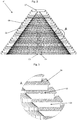
- Fig. 1 shows a catalyst support system 01 to be arranged in the lover part of a chemical reactor (not shown) above and around an opening (not shown) of the reactor.
- the reactor is partly filled with catalyst (not shown), which is arranged above and possibly also around the catalyst support system.
- the catalyst support system guards the reactor opening from catalyst entering or exiting the reactor opening.
- the catalyst support system comprises a plurality of bricks 02 arranged in layers with circular shape. The layers are arranged on top of each other, each circular layer has a smaller diameter than the layer it is arranged on top of, whereby the total catalyst support system obtains a cone-like shape.
- the top of the catalyst support system may comprise a flat mono block 07, to close the top of the cone, so no catalyst may enter.
- the cone height may be varied by varying the diameter of the flat mono block.
- the bricks each comprise brick legs 03 and brick shoulders 04 which form process fluid flow channels 05 between them, and anti-blocking means 06 in the form of ramparts, which can be seen and will be explained in more detail in the following.
- the flow channels in this embodiment runs radially in the circular brick layers, whereas the distance between each layer of ramparts forms circular gaps for the process flow to flow through, outside the flow channels.
- the bricks may not have flow channels, which only slightly affects the total cross sectional flow area of the catalyst support system, since the top layers have relative small diameters compared to the lower layers.
- FIG. 2 A cross sectional view of the catalyst support system of Fig. 1 is shown on Fig. 2 .
- the inner part of the cone shaped catalyst support system is hollow, which allows for the reactor opening to be positioned beneath the cone.
- the cone can be assembled layer by layer without the risk of collapsing inwards.
- a cut sectional view (A) of the catalyst support system shown in Fig. 2 (and 1 ) is seen in more detail in Fig. 3 .
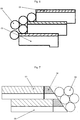
- the anti-blocking means 06 is in cross sectional shape of a triangle with rounded corners. A strong and crack resistant shape, protecting the brick legs 03 and flow channels against process fluid flow blocking and against mechanical damage from contact with catalyst or other reactor parts (not shown). Also seen is the slight "step", the 90° corner between the top of the brick and the rampart. The next brick layered on top of a brick will rest against this step, which prevents it from sliding outwards relative to the brick(s) in the layer below, which is also seen in the detail cross sectional view of Fig. 4 .
- Fig. 5 an embodiment is shown, where the construction of the bricks and ramparts in the catalyst support system is similar to the foregoing figures, but it is shown how catalyst or inert particles in the reactor, in this case in the form of spheres 09 rests upon the outer surface of the catalyst support system.
- the distance between the ramparts is smaller than the diameter of the spheres, which therefore rest upon the rampart which hence protects the more fragile brick legs from contact with the spheres, contrary to known art as shown in Fig. 6 , where the spheres have direct contact with the brick legs. Because of the sturdy construction and geometry of the rampart, there is less risk of breakage and damage by contact with the spheres with the load of the whole catalyst bed above.
- the reactor may comprise a bed of catalyst as well as inert particles of different shape.
- the bed may comprise inert spheres in contact with the catalyst support system in the bottom of the bed and catalyst particles which may have a different geometrical shape and size than the spheres in the upper part of the bed, on top of the spheres.
- the spheres may also comprise catalytic active material.
- the anti-blocking members are integrated with the bricks.
- a further embodiment as shown in Fig. 7 has anti-blocking means which are not integrated with the bricks, but arranged on the outside of the bricks. This enables the anti-blocking means to be replaced without replacing the inner bricks.
- the bricks may be slightly wedge-shaped as seen in Fig. 8 , whereby the shoulders of the bricks are able to contact adjacent brick shoulders on the entire shoulder side area when the circle shaped brick layer is formed. As the layer diameter decreases upwards in the cone shaped catalyst support system, the wedge-angle of each brick will be increased to maintain this tight geometrical fit of the brick shoulders.
- the brick legs shown in Fig 8 refers to known art catalyst support system, where it was necessary to have a larger cross sectional area of the flow channels in the bricks outwards facing side, to compensate for the partly blocking of the flow channel by reactor particles such as catalyst or inert particles. But according to this invention, as shown in Fig.
Landscapes
- Chemical & Material Sciences (AREA)
- Organic Chemistry (AREA)
- Chemical Kinetics & Catalysis (AREA)
- Physics & Mathematics (AREA)
- Fluid Mechanics (AREA)
- Physical Or Chemical Processes And Apparatus (AREA)
- Devices And Processes Conducted In The Presence Of Fluids And Solid Particles (AREA)
Claims (21)
- Réacteur chimique qui possède un catalyseur du type à lit fixe, qui comprend un système de support de catalyseur qui est disposé dans la partie inférieure du réacteur pour faire écran entre au moins une ouverture dans la partie inférieure du réacteur par rapport au catalyseur en question, le système de support de catalyseur comprenant des canaux d'écoulement qui permettent à un fluide de traitement de s'écouler dans la direction du réacteur ou à partir de celui-ci en passant par ladite ouverture du réacteur, dans lequel le système de support de catalyseur comprend en outre des moyens qui s'opposent à l'obturation, destinés à empêcher l'obturation desdits canaux d'écoulement, lesdits moyens qui s'opposent à l'obturation comprenant un labyrinthe d'écoulement géométrique qui comprend une face externe du système du catalyseur qui présente une aire d'écoulement totale en section transversale supérieure à l'aire d'écoulement totale en section transversale des canaux d'écoulement.
- Réacteur chimique selon la revendication 1, dans lequel l'aire d'écoulement en section transversale de la face externe du système de support de catalyseur représente entre 1,1 et 4,0 ou entre 1,1 et 2,0 ou entre 1,2 et 1,7 fois l'aire d'écoulement totale en section transversale des canaux d'écoulement.
- Réacteur chimique selon l'une quelconque des revendications précédentes, dans lequel les moyens qui s'opposent à l'obturation comprennent des remparts.
- Réacteur chimique selon l'une quelconque des revendications précédentes, dans lequel le système de support de catalyseur comprend un certain nombre de briques qui comprennent lesdits canaux d'écoulement.
- Réacteur chimique selon la revendication 4, dans lequel lesdites briques sont conçues pour former un système de support de catalyseur qui se présente sous la forme d'un cône, d'un dôme, d'une voûte, d'un cylindre, d'une pyramide, d'un cône inversé, d'un demi beignet ou qui possède une forme plate.
- Réacteur chimique selon la revendication 5, dans lequel lesdites briques sont conçues pour être disposées en couches afin d'obtenir le système de support de catalyseur.
- Réacteur chimique selon l'une quelconque des revendications 5 à 6, dans lequel lesdites briques comprennent une ou plusieurs jambes de briques et une ou plusieurs épaules de briques, et lesdits canaux d'écoulement sont réalisés entre lesdites jambes de briques.
- Réacteur chimique selon l'une quelconque des revendications 5 à 6, dans lequel lesdites briques comprennent des éléments d'espacement faisant saillie, et lesdits canaux d'écoulement sont réalisés entre lesdits éléments d'espacement faisant saillie.
- Réacteur chimique selon l'une quelconque des revendications 5 à 6, dans lequel lesdites briques sont creuses, et lesdits canaux d'écoulement sont réalisés dans l'espace creux au sein des briques.
- Réacteur chimique selon l'une quelconque des revendications précédentes, dans lequel lesdits canaux d'écoulement possèdent une aire d'écoulement uniforme en section transversale à travers le système de support de catalyseur.
- Réacteur chimique selon l'une quelconque des revendications 5 à 6, dans lequel les moyens qui s'opposent à l'obturation font partie intégrante desdites briques.
- Réacteur chimique selon l'une quelconque des revendications précédentes, dans lequel les moyens qui s'opposent à l'obturation représentent des éléments oblongs qui sont disposés perpendiculairement aux canaux d'écoulement.
- Réacteur chimique selon l'une quelconque des revendications précédentes, dans lequel les moyens qui s'opposent à l'obturation possèdent une configuration en section transversale de forme triangulaire et des coins arrondis.
- Réacteur chimique selon l'une quelconque des revendications précédentes, dans lequel les moyens qui s'opposent à l'obturation représentent des éléments indépendants qui sont disposés à l'extérieur dudit système de support de catalyseur.
- Réacteur chimique selon l'une quelconque des revendications précédentes, qui comprend en outre des éléments inertes ou un catalyseur disposés autour dudit système de support de catalyseur et qui possède(nt) une configuration géométrique qui est prévue pour s'appuyer sur lesdits moyens qui s'opposent à l'obturation, tout en permettant l'écoulement d'un fluide de traitement à travers lesdits canaux d'écoulement.
- Réacteur chimique selon la revendication 15, dans lequel les éléments inertes en question sont des sphères.
- Réacteur chimique selon la revendication 15, dans lequel les éléments inertes en question possèdent une configuration de forme annulaire.
- Réacteur chimique selon la revendication 15, dans lequel les éléments inertes en question sont des morceaux qui possèdent une configuration de forme aléatoire.
- Réacteur chimique selon la revendication 15, dans lequel les particules manifestant une activité catalytique sont disposées autour dudit système de support de catalyseur.
- Réacteur chimique selon la revendication 16, 17 ou 18, dans lequel la configuration des particules inertes possède la même dimension ou une dimension supérieure à la largeur de la fente des moyens qui s'opposent à l'obturation, ou, de manière spécifique, lesdites particules présentent une granulométrie supérieure à concurrence de 1,05 à 4,0, de manière plus spécifique à concurrence de 1,8 à 3,5 fois la largeur de la fente.
- Réacteur chimique selon la revendication 19, dans lequel la configuration des particules de catalyseur possède la même dimension ou une dimension supérieure à la largeur de la fente des moyens qui s'opposent à l'obturation, ou, de manière spécifique, lesdites particules présentent une granulométrie supérieure à concurrence de 1,05 à 4,0, de manière plus spécifique à concurrence de 1,1 à 1,7 fois la largeur de la fente.
Applications Claiming Priority (2)
| Application Number | Priority Date | Filing Date | Title |
|---|---|---|---|
| DKPA201700131 | 2017-02-27 | ||
| PCT/EP2018/054337 WO2018153955A1 (fr) | 2017-02-27 | 2018-02-22 | Réacteur chimique avec système de support de catalyseur |
Publications (2)
| Publication Number | Publication Date |
|---|---|
| EP3585508A1 EP3585508A1 (fr) | 2020-01-01 |
| EP3585508B1 true EP3585508B1 (fr) | 2021-09-15 |
Family
ID=61691434
Family Applications (1)
| Application Number | Title | Priority Date | Filing Date |
|---|---|---|---|
| EP18711825.2A Active EP3585508B1 (fr) | 2017-02-27 | 2018-02-22 | Réacteur chimique avec système de support de catalyseur |
Country Status (14)
| Country | Link |
|---|---|
| US (1) | US10661241B2 (fr) |
| EP (1) | EP3585508B1 (fr) |
| KR (1) | KR102535582B1 (fr) |
| CN (1) | CN110325270B (fr) |
| AU (1) | AU2018225388B2 (fr) |
| BR (1) | BR112019017838A2 (fr) |
| EA (1) | EA039388B1 (fr) |
| ES (1) | ES2895827T3 (fr) |
| HU (1) | HUE057143T2 (fr) |
| MX (1) | MX2019010020A (fr) |
| MY (1) | MY195988A (fr) |
| SA (1) | SA519402543B1 (fr) |
| UA (1) | UA125796C2 (fr) |
| WO (1) | WO2018153955A1 (fr) |
Families Citing this family (1)
| Publication number | Priority date | Publication date | Assignee | Title |
|---|---|---|---|---|
| CN109939638B (zh) * | 2019-05-08 | 2024-01-30 | 张化机(苏州)重装有限公司 | 一种填料支撑装置 |
Family Cites Families (15)
| Publication number | Priority date | Publication date | Assignee | Title |
|---|---|---|---|---|
| US2899286A (en) * | 1959-08-11 | Catalyst bed support | ||
| US3818667A (en) * | 1971-03-22 | 1974-06-25 | Universal Oil Prod Co | Louvered screen support member for particulate material |
| GB1473173A (en) | 1974-06-12 | 1977-05-11 | Uop Inc | Louvered screen support member for particulate material |
| DE2526632C3 (de) | 1975-06-14 | 1983-02-10 | Raschig Gmbh, 6700 Ludwigshafen | Gitterförmiger Tragrost für regellos geschüttete Füllkörper in Stoffaustauschkolonnen |
| US4764347A (en) | 1983-04-05 | 1988-08-16 | Milligan John D | Grid plate assembly for ebullated bed reactor |
| US4814117A (en) | 1987-12-21 | 1989-03-21 | Max Leva | Packing support for gas - liquid contact towers |
| FR2730423B1 (fr) * | 1995-02-15 | 1997-03-21 | Air Liquide | Agencement d'une grille de retenue d'un materiau actif dans un recipient, et recipient ainsi equipe |
| US6217832B1 (en) * | 1998-04-30 | 2001-04-17 | Catalytica, Inc. | Support structures for a catalyst |
| GB9922940D0 (en) * | 1999-09-29 | 1999-12-01 | Ici Plc | Catalytic reactor |
| US6835354B2 (en) | 2000-04-05 | 2004-12-28 | Hyradix, Inc. | Integrated reactor |
| WO2006130558A2 (fr) * | 2005-06-01 | 2006-12-07 | The Board Of Trustees Of The University Of Illinois | Structures souples pour capteurs et elements electroniques |
| EP1820569A1 (fr) * | 2006-01-20 | 2007-08-22 | Ineos Europe Limited | Procede pour contacter un hydrocarbure et un gaz contenant d'oxygene avec un lit de catalyseur |
| CN201154301Y (zh) * | 2007-12-13 | 2008-11-26 | 中国石油化工股份有限公司 | 一种固定床反应器内构件 |
| CN202212181U (zh) * | 2011-08-01 | 2012-05-09 | 中国石油化工股份有限公司 | 一种在线置换式反应器支撑筛板 |
| CN202606129U (zh) * | 2012-04-27 | 2012-12-19 | 长岭炼化岳阳工程设计有限公司 | 非金属高温催化剂支承件 |
-
2018
- 2018-02-22 UA UAA201910019A patent/UA125796C2/uk unknown
- 2018-02-22 BR BR112019017838A patent/BR112019017838A2/pt not_active Application Discontinuation
- 2018-02-22 ES ES18711825T patent/ES2895827T3/es active Active
- 2018-02-22 WO PCT/EP2018/054337 patent/WO2018153955A1/fr not_active Ceased
- 2018-02-22 EP EP18711825.2A patent/EP3585508B1/fr active Active
- 2018-02-22 MX MX2019010020A patent/MX2019010020A/es unknown
- 2018-02-22 US US16/477,078 patent/US10661241B2/en active Active
- 2018-02-22 HU HUE18711825A patent/HUE057143T2/hu unknown
- 2018-02-22 AU AU2018225388A patent/AU2018225388B2/en active Active
- 2018-02-22 MY MYPI2019004837A patent/MY195988A/en unknown
- 2018-02-22 EA EA201991975A patent/EA039388B1/ru unknown
- 2018-02-22 CN CN201880014242.2A patent/CN110325270B/zh active Active
- 2018-02-22 KR KR1020197026002A patent/KR102535582B1/ko active Active
-
2019
- 2019-08-26 SA SA519402543A patent/SA519402543B1/ar unknown
Also Published As
| Publication number | Publication date |
|---|---|
| SA519402543B1 (ar) | 2023-01-03 |
| ES2895827T3 (es) | 2022-02-22 |
| US10661241B2 (en) | 2020-05-26 |
| CN110325270A (zh) | 2019-10-11 |
| CA3050834A1 (fr) | 2018-08-30 |
| HUE057143T2 (hu) | 2022-04-28 |
| BR112019017838A2 (pt) | 2020-04-14 |
| MY195988A (en) | 2023-02-27 |
| AU2018225388A1 (en) | 2019-08-22 |
| EA201991975A1 (ru) | 2020-01-17 |
| KR102535582B1 (ko) | 2023-05-23 |
| CN110325270B (zh) | 2022-06-17 |
| UA125796C2 (uk) | 2022-06-08 |
| WO2018153955A1 (fr) | 2018-08-30 |
| EA039388B1 (ru) | 2022-01-21 |
| KR20190118170A (ko) | 2019-10-17 |
| AU2018225388B2 (en) | 2023-06-15 |
| EP3585508A1 (fr) | 2020-01-01 |
| US20190329206A1 (en) | 2019-10-31 |
| MX2019010020A (es) | 2019-10-15 |
Similar Documents
| Publication | Publication Date | Title |
|---|---|---|
| US8221512B2 (en) | Hydrogen generator and fuel cell system | |
| EP3136487B1 (fr) | Appareil de génération d'hydrogène et système de pile à combustible | |
| US5484577A (en) | Catalytic hydrocarbon reformer with enhanced internal heat transfer mechanism | |
| RU2673527C2 (ru) | Паровой риформинг | |
| US8377386B2 (en) | Catalytic reactor | |
| CZ331995A3 (en) | Apparatus for carrying out endothermic reaction and process for carrying out such endothermic reaction | |
| KR20230042654A (ko) | 수증기 방출을 감소시킨 합성 가스 제조 공정 | |
| CA3109648A1 (fr) | Reformage a la vapeur ou a sec d'hydrocarbures | |
| EP3585508B1 (fr) | Réacteur chimique avec système de support de catalyseur | |
| CA3050834C (fr) | Reacteur chimique avec systeme de support de catalyseur | |
| WO2011075874A1 (fr) | Dispositif de distribution de combustible et brûleur | |
| JP2001342002A (ja) | 燃料改質器 | |
| EP3414000B1 (fr) | Réacteur endothermique à efficacité améliorée pour la production de gaz de synthèse avec une récupération de chaleur flexible pour répondre à la génération de vapeur d'exportation faible | |
| KR100761945B1 (ko) | 가스연료처리기 | |
| US10974219B2 (en) | Micro reformer | |
| KR20250079813A (ko) | 이중관 구조를 가지는 연료 개질장치 | |
| KR20250157666A (ko) | 연료 개질기 | |
| KR20250131960A (ko) | 연료전지 개질기 | |
| HK1245381B (en) | Catalytic burner arrangement | |
| HK1245381A1 (en) | Catalytic burner arrangement |
Legal Events
| Date | Code | Title | Description |
|---|---|---|---|
| STAA | Information on the status of an ep patent application or granted ep patent |
Free format text: STATUS: UNKNOWN |
|
| STAA | Information on the status of an ep patent application or granted ep patent |
Free format text: STATUS: THE INTERNATIONAL PUBLICATION HAS BEEN MADE |
|
| PUAI | Public reference made under article 153(3) epc to a published international application that has entered the european phase |
Free format text: ORIGINAL CODE: 0009012 |
|
| STAA | Information on the status of an ep patent application or granted ep patent |
Free format text: STATUS: REQUEST FOR EXAMINATION WAS MADE |
|
| 17P | Request for examination filed |
Effective date: 20190826 |
|
| AK | Designated contracting states |
Kind code of ref document: A1 Designated state(s): AL AT BE BG CH CY CZ DE DK EE ES FI FR GB GR HR HU IE IS IT LI LT LU LV MC MK MT NL NO PL PT RO RS SE SI SK SM TR |
|
| AX | Request for extension of the european patent |
Extension state: BA ME |
|
| DAV | Request for validation of the european patent (deleted) | ||
| DAX | Request for extension of the european patent (deleted) | ||
| GRAP | Despatch of communication of intention to grant a patent |
Free format text: ORIGINAL CODE: EPIDOSNIGR1 |
|
| STAA | Information on the status of an ep patent application or granted ep patent |
Free format text: STATUS: GRANT OF PATENT IS INTENDED |
|
| INTG | Intention to grant announced |
Effective date: 20210531 |
|
| GRAS | Grant fee paid |
Free format text: ORIGINAL CODE: EPIDOSNIGR3 |
|
| GRAA | (expected) grant |
Free format text: ORIGINAL CODE: 0009210 |
|
| STAA | Information on the status of an ep patent application or granted ep patent |
Free format text: STATUS: THE PATENT HAS BEEN GRANTED |
|
| AK | Designated contracting states |
Kind code of ref document: B1 Designated state(s): AL AT BE BG CH CY CZ DE DK EE ES FI FR GB GR HR HU IE IS IT LI LT LU LV MC MK MT NL NO PL PT RO RS SE SI SK SM TR |
|
| REG | Reference to a national code |
Ref country code: CH Ref legal event code: EP |
|
| REG | Reference to a national code |
Ref country code: DE Ref legal event code: R096 Ref document number: 602018023573 Country of ref document: DE |
|
| REG | Reference to a national code |
Ref country code: IE Ref legal event code: FG4D |
|
| REG | Reference to a national code |
Ref country code: AT Ref legal event code: REF Ref document number: 1430109 Country of ref document: AT Kind code of ref document: T Effective date: 20211015 |
|
| REG | Reference to a national code |
Ref country code: NL Ref legal event code: FP |
|
| REG | Reference to a national code |
Ref country code: SE Ref legal event code: TRGR |
|
| REG | Reference to a national code |
Ref country code: LT Ref legal event code: MG9D |
|
| PG25 | Lapsed in a contracting state [announced via postgrant information from national office to epo] |
Ref country code: RS Free format text: LAPSE BECAUSE OF FAILURE TO SUBMIT A TRANSLATION OF THE DESCRIPTION OR TO PAY THE FEE WITHIN THE PRESCRIBED TIME-LIMIT Effective date: 20210915 Ref country code: FI Free format text: LAPSE BECAUSE OF FAILURE TO SUBMIT A TRANSLATION OF THE DESCRIPTION OR TO PAY THE FEE WITHIN THE PRESCRIBED TIME-LIMIT Effective date: 20210915 Ref country code: HR Free format text: LAPSE BECAUSE OF FAILURE TO SUBMIT A TRANSLATION OF THE DESCRIPTION OR TO PAY THE FEE WITHIN THE PRESCRIBED TIME-LIMIT Effective date: 20210915 Ref country code: NO Free format text: LAPSE BECAUSE OF FAILURE TO SUBMIT A TRANSLATION OF THE DESCRIPTION OR TO PAY THE FEE WITHIN THE PRESCRIBED TIME-LIMIT Effective date: 20211215 Ref country code: LT Free format text: LAPSE BECAUSE OF FAILURE TO SUBMIT A TRANSLATION OF THE DESCRIPTION OR TO PAY THE FEE WITHIN THE PRESCRIBED TIME-LIMIT Effective date: 20210915 Ref country code: BG Free format text: LAPSE BECAUSE OF FAILURE TO SUBMIT A TRANSLATION OF THE DESCRIPTION OR TO PAY THE FEE WITHIN THE PRESCRIBED TIME-LIMIT Effective date: 20211215 |
|
| REG | Reference to a national code |
Ref country code: ES Ref legal event code: FG2A Ref document number: 2895827 Country of ref document: ES Kind code of ref document: T3 Effective date: 20220222 |
|
| PG25 | Lapsed in a contracting state [announced via postgrant information from national office to epo] |
Ref country code: LV Free format text: LAPSE BECAUSE OF FAILURE TO SUBMIT A TRANSLATION OF THE DESCRIPTION OR TO PAY THE FEE WITHIN THE PRESCRIBED TIME-LIMIT Effective date: 20210915 Ref country code: GR Free format text: LAPSE BECAUSE OF FAILURE TO SUBMIT A TRANSLATION OF THE DESCRIPTION OR TO PAY THE FEE WITHIN THE PRESCRIBED TIME-LIMIT Effective date: 20211216 |
|
| REG | Reference to a national code |
Ref country code: HU Ref legal event code: AG4A Ref document number: E057143 Country of ref document: HU |
|
| PG25 | Lapsed in a contracting state [announced via postgrant information from national office to epo] |
Ref country code: IS Free format text: LAPSE BECAUSE OF FAILURE TO SUBMIT A TRANSLATION OF THE DESCRIPTION OR TO PAY THE FEE WITHIN THE PRESCRIBED TIME-LIMIT Effective date: 20220115 Ref country code: SM Free format text: LAPSE BECAUSE OF FAILURE TO SUBMIT A TRANSLATION OF THE DESCRIPTION OR TO PAY THE FEE WITHIN THE PRESCRIBED TIME-LIMIT Effective date: 20210915 Ref country code: SK Free format text: LAPSE BECAUSE OF FAILURE TO SUBMIT A TRANSLATION OF THE DESCRIPTION OR TO PAY THE FEE WITHIN THE PRESCRIBED TIME-LIMIT Effective date: 20210915 Ref country code: RO Free format text: LAPSE BECAUSE OF FAILURE TO SUBMIT A TRANSLATION OF THE DESCRIPTION OR TO PAY THE FEE WITHIN THE PRESCRIBED TIME-LIMIT Effective date: 20210915 Ref country code: PT Free format text: LAPSE BECAUSE OF FAILURE TO SUBMIT A TRANSLATION OF THE DESCRIPTION OR TO PAY THE FEE WITHIN THE PRESCRIBED TIME-LIMIT Effective date: 20220117 Ref country code: PL Free format text: LAPSE BECAUSE OF FAILURE TO SUBMIT A TRANSLATION OF THE DESCRIPTION OR TO PAY THE FEE WITHIN THE PRESCRIBED TIME-LIMIT Effective date: 20210915 Ref country code: EE Free format text: LAPSE BECAUSE OF FAILURE TO SUBMIT A TRANSLATION OF THE DESCRIPTION OR TO PAY THE FEE WITHIN THE PRESCRIBED TIME-LIMIT Effective date: 20210915 Ref country code: CZ Free format text: LAPSE BECAUSE OF FAILURE TO SUBMIT A TRANSLATION OF THE DESCRIPTION OR TO PAY THE FEE WITHIN THE PRESCRIBED TIME-LIMIT Effective date: 20210915 Ref country code: AL Free format text: LAPSE BECAUSE OF FAILURE TO SUBMIT A TRANSLATION OF THE DESCRIPTION OR TO PAY THE FEE WITHIN THE PRESCRIBED TIME-LIMIT Effective date: 20210915 |
|
| REG | Reference to a national code |
Ref country code: DE Ref legal event code: R097 Ref document number: 602018023573 Country of ref document: DE |
|
| PLBE | No opposition filed within time limit |
Free format text: ORIGINAL CODE: 0009261 |
|
| STAA | Information on the status of an ep patent application or granted ep patent |
Free format text: STATUS: NO OPPOSITION FILED WITHIN TIME LIMIT |
|
| PG25 | Lapsed in a contracting state [announced via postgrant information from national office to epo] |
Ref country code: DK Free format text: LAPSE BECAUSE OF FAILURE TO SUBMIT A TRANSLATION OF THE DESCRIPTION OR TO PAY THE FEE WITHIN THE PRESCRIBED TIME-LIMIT Effective date: 20210915 |
|
| 26N | No opposition filed |
Effective date: 20220616 |
|
| PG25 | Lapsed in a contracting state [announced via postgrant information from national office to epo] |
Ref country code: SI Free format text: LAPSE BECAUSE OF FAILURE TO SUBMIT A TRANSLATION OF THE DESCRIPTION OR TO PAY THE FEE WITHIN THE PRESCRIBED TIME-LIMIT Effective date: 20210915 |
|
| PG25 | Lapsed in a contracting state [announced via postgrant information from national office to epo] |
Ref country code: MC Free format text: LAPSE BECAUSE OF FAILURE TO SUBMIT A TRANSLATION OF THE DESCRIPTION OR TO PAY THE FEE WITHIN THE PRESCRIBED TIME-LIMIT Effective date: 20210915 |
|
| PG25 | Lapsed in a contracting state [announced via postgrant information from national office to epo] |
Ref country code: LU Free format text: LAPSE BECAUSE OF NON-PAYMENT OF DUE FEES Effective date: 20220222 |
|
| REG | Reference to a national code |
Ref country code: AT Ref legal event code: UEP Ref document number: 1430109 Country of ref document: AT Kind code of ref document: T Effective date: 20210915 |
|
| PG25 | Lapsed in a contracting state [announced via postgrant information from national office to epo] |
Ref country code: IE Free format text: LAPSE BECAUSE OF NON-PAYMENT OF DUE FEES Effective date: 20220222 |
|
| P01 | Opt-out of the competence of the unified patent court (upc) registered |
Effective date: 20230602 |
|
| PG25 | Lapsed in a contracting state [announced via postgrant information from national office to epo] |
Ref country code: MK Free format text: LAPSE BECAUSE OF FAILURE TO SUBMIT A TRANSLATION OF THE DESCRIPTION OR TO PAY THE FEE WITHIN THE PRESCRIBED TIME-LIMIT Effective date: 20210915 Ref country code: CY Free format text: LAPSE BECAUSE OF FAILURE TO SUBMIT A TRANSLATION OF THE DESCRIPTION OR TO PAY THE FEE WITHIN THE PRESCRIBED TIME-LIMIT Effective date: 20210915 |
|
| PG25 | Lapsed in a contracting state [announced via postgrant information from national office to epo] |
Ref country code: MT Free format text: LAPSE BECAUSE OF FAILURE TO SUBMIT A TRANSLATION OF THE DESCRIPTION OR TO PAY THE FEE WITHIN THE PRESCRIBED TIME-LIMIT Effective date: 20210915 |
|
| REG | Reference to a national code |
Ref country code: CH Ref legal event code: U11 Free format text: ST27 STATUS EVENT CODE: U-0-0-U10-U11 (AS PROVIDED BY THE NATIONAL OFFICE) Effective date: 20260301 |
|
| PGFP | Annual fee paid to national office [announced via postgrant information from national office to epo] |
Ref country code: NL Payment date: 20260220 Year of fee payment: 9 |
|
| PGFP | Annual fee paid to national office [announced via postgrant information from national office to epo] |
Ref country code: HU Payment date: 20260223 Year of fee payment: 9 |
|
| PGFP | Annual fee paid to national office [announced via postgrant information from national office to epo] |
Ref country code: SE Payment date: 20260223 Year of fee payment: 9 |
|
| PGFP | Annual fee paid to national office [announced via postgrant information from national office to epo] |
Ref country code: GB Payment date: 20260223 Year of fee payment: 9 |
|
| PGFP | Annual fee paid to national office [announced via postgrant information from national office to epo] |
Ref country code: ES Payment date: 20260317 Year of fee payment: 9 |
|
| PGFP | Annual fee paid to national office [announced via postgrant information from national office to epo] |
Ref country code: DE Payment date: 20260220 Year of fee payment: 9 |
|
| PGFP | Annual fee paid to national office [announced via postgrant information from national office to epo] |
Ref country code: AT Payment date: 20260218 Year of fee payment: 9 |
|
| PGFP | Annual fee paid to national office [announced via postgrant information from national office to epo] |
Ref country code: BE Payment date: 20260220 Year of fee payment: 9 Ref country code: IT Payment date: 20260220 Year of fee payment: 9 |
|
| PGFP | Annual fee paid to national office [announced via postgrant information from national office to epo] |
Ref country code: FR Payment date: 20260224 Year of fee payment: 9 |
|
| PGFP | Annual fee paid to national office [announced via postgrant information from national office to epo] |
Ref country code: TR Payment date: 20260210 Year of fee payment: 9 |
|
| PGFP | Annual fee paid to national office [announced via postgrant information from national office to epo] |
Ref country code: CH Payment date: 20260301 Year of fee payment: 9 |