EP3584909A1 - Machine électrique dotée d'une enveloppe de fluide refroidissant - Google Patents
Machine électrique dotée d'une enveloppe de fluide refroidissant Download PDFInfo
- Publication number
- EP3584909A1 EP3584909A1 EP18178568.4A EP18178568A EP3584909A1 EP 3584909 A1 EP3584909 A1 EP 3584909A1 EP 18178568 A EP18178568 A EP 18178568A EP 3584909 A1 EP3584909 A1 EP 3584909A1
- Authority
- EP
- European Patent Office
- Prior art keywords
- electrical machine
- stator
- cooling
- liquid jacket
- strips
- Prior art date
- Legal status (The legal status is an assumption and is not a legal conclusion. Google has not performed a legal analysis and makes no representation as to the accuracy of the status listed.)
- Withdrawn
Links
Images


Classifications
-
- H—ELECTRICITY
- H02—GENERATION; CONVERSION OR DISTRIBUTION OF ELECTRIC POWER
- H02K—DYNAMO-ELECTRIC MACHINES
- H02K5/00—Casings; Enclosures; Supports
- H02K5/04—Casings or enclosures characterised by the shape, form or construction thereof
- H02K5/20—Casings or enclosures characterised by the shape, form or construction thereof with channels or ducts for flow of cooling medium
- H02K5/203—Casings or enclosures characterised by the shape, form or construction thereof with channels or ducts for flow of cooling medium specially adapted for liquids, e.g. cooling jackets
-
- H—ELECTRICITY
- H02—GENERATION; CONVERSION OR DISTRIBUTION OF ELECTRIC POWER
- H02K—DYNAMO-ELECTRIC MACHINES
- H02K7/00—Arrangements for handling mechanical energy structurally associated with dynamo-electric machines, e.g. structural association with mechanical driving motors or auxiliary dynamo-electric machines
- H02K7/006—Structural association of a motor or generator with the drive train of a motor vehicle
-
- B—PERFORMING OPERATIONS; TRANSPORTING
- B60—VEHICLES IN GENERAL
- B60K—ARRANGEMENT OR MOUNTING OF PROPULSION UNITS OR OF TRANSMISSIONS IN VEHICLES; ARRANGEMENT OR MOUNTING OF PLURAL DIVERSE PRIME-MOVERS IN VEHICLES; AUXILIARY DRIVES FOR VEHICLES; INSTRUMENTATION OR DASHBOARDS FOR VEHICLES; ARRANGEMENTS IN CONNECTION WITH COOLING, AIR INTAKE, GAS EXHAUST OR FUEL SUPPLY OF PROPULSION UNITS IN VEHICLES
- B60K1/00—Arrangement or mounting of electrical propulsion units
-
- H—ELECTRICITY
- H02—GENERATION; CONVERSION OR DISTRIBUTION OF ELECTRIC POWER
- H02K—DYNAMO-ELECTRIC MACHINES
- H02K9/00—Arrangements for cooling or ventilating
- H02K9/19—Arrangements for cooling or ventilating for machines with closed casing and closed-circuit cooling using a liquid cooling medium, e.g. oil
-
- B—PERFORMING OPERATIONS; TRANSPORTING
- B60—VEHICLES IN GENERAL
- B60K—ARRANGEMENT OR MOUNTING OF PROPULSION UNITS OR OF TRANSMISSIONS IN VEHICLES; ARRANGEMENT OR MOUNTING OF PLURAL DIVERSE PRIME-MOVERS IN VEHICLES; AUXILIARY DRIVES FOR VEHICLES; INSTRUMENTATION OR DASHBOARDS FOR VEHICLES; ARRANGEMENTS IN CONNECTION WITH COOLING, AIR INTAKE, GAS EXHAUST OR FUEL SUPPLY OF PROPULSION UNITS IN VEHICLES
- B60K1/00—Arrangement or mounting of electrical propulsion units
- B60K2001/003—Arrangement or mounting of electrical propulsion units with means for cooling the electrical propulsion units
- B60K2001/006—Arrangement or mounting of electrical propulsion units with means for cooling the electrical propulsion units the electric motors
-
- H—ELECTRICITY
- H02—GENERATION; CONVERSION OR DISTRIBUTION OF ELECTRIC POWER
- H02K—DYNAMO-ELECTRIC MACHINES
- H02K1/00—Details of the magnetic circuit
- H02K1/06—Details of the magnetic circuit characterised by the shape, form or construction
- H02K1/22—Rotating parts of the magnetic circuit
- H02K1/32—Rotating parts of the magnetic circuit with channels or ducts for flow of cooling medium
Definitions
- the invention relates to an electrical machine with water jacket cooling and its use, in particular in electrically powered vehicles.
- Dynamoelectric machines e.g. Asynchronous machines with squirrel-cage rotors or permanently excited machines are provided with water jacket cooling if they are designed to be highly utilized and encapsulated. This is necessary to: to ensure heat dissipation of the rotor and, if necessary, the winding head of the stator.
- the entire surface of the stator is positioned as far as possible.
- Axial internal air channels in the laminated core of the stator would lead to larger yoke cross sections in order to be able to guarantee the required magnetic flux.
- the restricted magnetic cross section of the stator would thus lead to a reduction in the radial heat conduction of the winding current heat losses in the winding system and iron losses, that is to say hysteresis and eddy current losses in the water jacket.
- dynamoelectric machines are used, for example, in electrically powered vehicles such as electric buses or rail vehicles, as well as in machine tools, where only a limited installation space is available, which can prevent efficient cooling.
- Air circulation in the front area of closed electrical machines and water jacket cooling of stators are known.
- the object of the invention is to provide efficient cooling of a highly utilized dynamo-electric machine which is particularly suitable for use in electrically driven vehicles and which, despite the compact, in particular mechanical connection, provides efficient cooling within the vehicle.
- the object is achieved by a vehicle, in particular a traction vehicle or electric bus with an electrical machine according to the invention, the electrical machine being fastened inside the vehicle via strips and / or the external cooling channels.
- both the stator is adequately cooled by direct contact with the water jacket and the rotor is closed by the closed internal cooling circuit.
- the internal cooling circuit is designed according to the invention in such a way that the liquid jacket has openings at some predetermined axial sections, so that the cooling medium is deflected out of the machine into the cooling channels located on the outer circumference and from there at the other axial end from these cooling channels into the machine.
- the liquid jacket or liquid cooling jacket forms a housing between the two end shields of the electrical machine.
- the liquid cooling jacket extends axially at least over the axial length of the laminated core of the stator.
- the liquid cooling jacket extends maximally axially from one end shield to the other end shield. In this way, the winding head of the stator winding system and / or the end shields can also be cooled.
- the liquid cooling jacket can be constructed as follows. An inner tube and an outer tube are almost congruent and have the same axial length and openings or openings.
- the liquid jacket has an inner tube which contains the openings or openings for the cooling channel or cooling channels and extends from one bearing plate to the other bearing plate.
- an outer tube spaced apart from the inner tube, the intermediate space forming the liquid jacket.
- Such cooling channels are advantageously arranged distributed on the outer circumference of the liquid jacket housing.
- an arrangement of the cooling channels opposite one another on both sides of the liquid jacket is particularly suitable in order to be able to use such an electrical machine particularly easily in a predetermined installation space of a vehicle or a machine tool.
- the cooling channels are advantageously U-shaped in their cross section.
- two strips are provided to design the cooling channel, which are connected to the liquid jacket housing at a predetermined distance, advantageously welded, a cover, for example a sheet metal, being fastened to the strips to cover this volume located between the strips. This creates a cooling channel on the outer circumference of the liquid jacket housing.
- this dynamoelectric machine can now be positioned in a suspension of a vehicle or within another predetermined installation space via the strips.
- This inventive combination of suspension and design of the cooling channel can thus be designed as a welded construction.
- Two steel strips are given in one welded parallel distance on the liquid jacket housing and welded a comparatively light cover plate, which is only suitable for guiding the cooling medium, for example of air or a liquid.
- these strips serve to guide the coolant or design the cooling channel on the outer circumference of the liquid jacket housing.
- the combination of suspension and cooling duct according to the invention can also be designed as a solid component, with e.g.
- a cooling channel is machined out of a thicker steel sheet or aluminum block. This one-piece element is then also positioned on the liquid jacket housing. When viewed in cross section, the legs of the cooling channel also form stable webs or strips, on which the electrical machine can be fixed and positioned in the vehicle or in an installation space.
- This design of the cooling principle results in a comparatively high efficiency of the machine.
- One cooling system is a liquid jacket cooling as a housing around the stator, which primarily removes the iron losses, that is to say hysteresis and eddy current losses.
- the other cooling system is an internal cooling circuit that, among other things, leads out of the rotor and possibly the winding heads of the stator to the outer circumference of the stator and releases it there to the liquid jacket cooling and / or the environment.
- Water is particularly suitable as the cooling medium for liquid jacket cooling, while the internal cooling circuit can have oil or gaseous media such as air as the cooling medium.
- the course of the cooling medium within the liquid jacket cooling can e.g. meandering or spiral around the stator.
- liquid jacket essentially consists of two coaxially arranged and spaced-apart cylinders, ie essentially an inner and an outer tube.
- the strips have fastening options, for example threaded holes, in order to be able to fasten the dynamoelectric machine, for example in a vehicle suspension.
- the attachment of the dynamoelectric machine, for example in a vehicle suspension thus also contributes to the torsional rigidity.
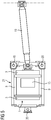
- FIG. 1 shows a dynamoelectric machine 1, which is arranged within a housing, the housing preferably being formed by a liquid jacket 2, the machine 1 can be sealed liquid-tight at the end faces by end shields 3.
- an all-round sealing seam 27 can be provided in this area.
- Water is preferably led through this liquid jacket 2 via inlets and outlets (not shown).
- An electrical supply to a winding system 6 of the electrical machine 1 takes place via a terminal box 15. Also shown here are strips 9 which are attached in parallel to the liquid jacket 2, in particular welded on, and have threaded holes 12. The two strips 9 enclose a space, which preferably forms an axially extending cooling channel 13 through a cover 11 (not shown in this illustration). The strips 9 are axially longer than the liquid cooling jacket 2, in particular at least by the axial extent of the openings 10.
- openings 10 are provided between the strips 9 in the region of the axial ends of the liquid jacket 2. These openings 10 run outside of the liquid jacket 2 and lead into the interior of the dynamoelectric machine 1.
- FIG 2 shows in a cross section a liquid jacket 2 of the dynamoelectric machine 1, into which the laminated core of a stator 5 is inserted or pressed in order to obtain a comparatively good thermal connection of the laminated core of the stator 5 to the liquid jacket 2.
- two opposite strips 9 are attached in pairs, which, connected by a cover 11, form an axially extending cooling channel 13. Both air and other cooling media can be conducted, conveyed and guided in this cooling channel 13.
- a closed cooling circuit thus represents the interior of the electrical machine 1 and the cooling channel or channels 13.
- the liquid jacket cooling itself is in particular meandering or spiral-shaped.
- liquid jacket 2 is shown in perspective, with the axially parallel strips 9 on the opposite sides, which form the cooling channel 13 radially outside the liquid jacket 2 through the cover 11.
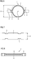
- cooling ducts can also be used multiple times be arranged on the circumference of the liquid jacket cooling, as is also the case FIG 6 shown in dashed lines.
- the installation height 22 is specified there by way of example, which does not permit a cooling channel design that is multiple in the circumferential direction.
- FIG 4 shows in one of the dynamo-electric machine 1 the laminated core of the stator 5 with its winding system 6, which forms winding heads 7 on the end faces of the laminated core.
- a rotor 8 which is also made of sheet metal, is arranged in a rotationally fixed manner on a shaft 4, which is held in the end shields 3 so as to be rotatable about an axis 16.
- the rotor 8 can be designed with a short-circuit cage 17 or as a permanently excited rotor 8.
- a short-circuit cage 17 within the laminated core of the rotor 8.
- one or more fan blades 26 are attached, preferably welded or cast, to a short-circuit ring of the short-circuit cage 17, which is attracted, inter alia, for the transport of the cooling medium of the internal cooling circuit.
- Recesses 14 in the rotor 8 run parallel to the shaft 4 and can lead a cooling medium from one side to the other end of the electrical machine 1.
- an internal cooling circuit can now be set up according to the invention, which runs radially outside the liquid jacket 2, that is to say radially outside the housing.
- the cooling flow 18 is recooled in the cooling channel 13 in its axial course and conducted on the other end face of the electrical machine 1 via the opening 10 again into the area of an end face with a winding head 7 and a short-circuit ring.
- the cooling medium then continues axially in the axially extending recesses 14 of the rotor 8 in order to emerge again on the other end face and again radially outside into the cooling channel or channels 13 via the other short-circuit ring and the winding head 7 and an opening 10 in the liquid jacket housing 2 of the liquid jacket 2 to arrive.
- the strips 9 not only take on the design of the cooling channel 13 but also serve to attach and suspend 21 in a vehicle. Furthermore, by designing the electrical machine 1, simple end shields 3 can now be used to fix the shaft 4.
- the cooling channels 13 radially outside of the liquid jacket 2 ideally lie opposite one another in order to be able to be fixed in a vehicle in a suitable manner.
- FIG 5 shows an example of a suspension 21 to which the dynamo-electric machine 1 is attached via the strips 9.
- the suspension 21 is positioned in the further mechanical construction of the vehicle via rubber buffers 20.
- the torque of the dynamoelectric machine 1 is guided to a propeller shaft 19 via the shaft 4.
- FIG 6 shows a side view of the dynamoelectric machine 1, which is positioned by means of the strips 9 of the cooling channels 13 in the suspension 21.
- the cooling channels 13 can be arranged on the circumference of the water jacket housing 2, but the maximum installation height 22 should not be exceeded. Examples of further possible cooling channels 13 are shown in dashed lines.
- the number of cooling channels 13 must basically correspond to the number of openings 10 to ensure proper cooling. Ie a cooling channel 13 requires two openings 10, two cooling channels 13 accordingly four openings 10 in the liquid jacket 2, as is also exemplified in FIG FIG 7 was shown.
- the liquid cooling jacket 2 is constructed as follows. An inner tube according to FIG 7 and an outer tube are almost congruent, have the same axial length 23. The outer tube has no openings 10. The inner tube has the openings 10. The liquid cooling jacket 2 extends from one bearing plate 3 to the other bearing plate 3, only interrupted by the opening or openings 10.
- FIG 8 Another version of the liquid cooling jacket according to FIG 8 , as in principle also the FIG 4 can be seen, has an inner tube 24, which contains the openings 10, extends from one bearing plate 3 to the other bearing plate 3 and is surrounded by an outer tube 25 in a predetermined axial area of the electrical machine 1. This axial area is at least the axial length of the laminated core of the stator 5 and forms the liquid cooling jacket 2.
- cooling medium for the liquid jacket 2 is water, which is supplied or discharged via inlets or outlets (not shown). Heat is removed from the laminated core of the stator 5, from the winding system 6 of the stator 5 and also from the winding head 7. Heat is also absorbed and dissipated by the internal cooling circuit, the heat also by the winding head 7, the rotor 8 and, depending on the guidance of the cooling flow 18, also the bearing plates 3 in the cooling channel 13.
- Gases are particularly suitable as the cooling medium of the internal cooling circuit, but also electrically insulating liquids such as oil.
Landscapes
- Engineering & Computer Science (AREA)
- Power Engineering (AREA)
- Chemical & Material Sciences (AREA)
- Combustion & Propulsion (AREA)
- Transportation (AREA)
- Mechanical Engineering (AREA)
- Motor Or Generator Cooling System (AREA)
Priority Applications (2)
| Application Number | Priority Date | Filing Date | Title |
|---|---|---|---|
| EP18178568.4A EP3584909A1 (fr) | 2018-06-19 | 2018-06-19 | Machine électrique dotée d'une enveloppe de fluide refroidissant |
| PCT/EP2019/063100 WO2019242966A1 (fr) | 2018-06-19 | 2019-05-21 | Machine électrique à refroidissement par revêtement de liquide |
Applications Claiming Priority (1)
| Application Number | Priority Date | Filing Date | Title |
|---|---|---|---|
| EP18178568.4A EP3584909A1 (fr) | 2018-06-19 | 2018-06-19 | Machine électrique dotée d'une enveloppe de fluide refroidissant |
Publications (1)
| Publication Number | Publication Date |
|---|---|
| EP3584909A1 true EP3584909A1 (fr) | 2019-12-25 |
Family
ID=62712887
Family Applications (1)
| Application Number | Title | Priority Date | Filing Date |
|---|---|---|---|
| EP18178568.4A Withdrawn EP3584909A1 (fr) | 2018-06-19 | 2018-06-19 | Machine électrique dotée d'une enveloppe de fluide refroidissant |
Country Status (2)
| Country | Link |
|---|---|
| EP (1) | EP3584909A1 (fr) |
| WO (1) | WO2019242966A1 (fr) |
Families Citing this family (1)
| Publication number | Priority date | Publication date | Assignee | Title |
|---|---|---|---|---|
| CN113923963B (zh) * | 2020-07-09 | 2023-03-24 | 比亚迪股份有限公司 | 车载电源装置及具有其的车辆 |
Citations (3)
| Publication number | Priority date | Publication date | Assignee | Title |
|---|---|---|---|---|
| US20130257197A1 (en) * | 2012-03-28 | 2013-10-03 | Siemens Aktiengesellschaft | Electric machine having efficient internal cooling |
| US20150069862A1 (en) * | 2012-04-10 | 2015-03-12 | Continental Automotive Gmbh | Casing for a Rotary Electric Machine, and Rotary Electric Machine Comprising a Casing |
| CN107040077A (zh) * | 2017-06-16 | 2017-08-11 | 重庆快星新能源汽车有限公司 | 一种智能温控液冷式车用动力电机 |
Family Cites Families (1)
| Publication number | Priority date | Publication date | Assignee | Title |
|---|---|---|---|---|
| EP0243800A1 (fr) * | 1986-04-23 | 1987-11-04 | Zwag AG | Carcasse pour machines électriques |
-
2018
- 2018-06-19 EP EP18178568.4A patent/EP3584909A1/fr not_active Withdrawn
-
2019
- 2019-05-21 WO PCT/EP2019/063100 patent/WO2019242966A1/fr active Application Filing
Patent Citations (3)
| Publication number | Priority date | Publication date | Assignee | Title |
|---|---|---|---|---|
| US20130257197A1 (en) * | 2012-03-28 | 2013-10-03 | Siemens Aktiengesellschaft | Electric machine having efficient internal cooling |
| US20150069862A1 (en) * | 2012-04-10 | 2015-03-12 | Continental Automotive Gmbh | Casing for a Rotary Electric Machine, and Rotary Electric Machine Comprising a Casing |
| CN107040077A (zh) * | 2017-06-16 | 2017-08-11 | 重庆快星新能源汽车有限公司 | 一种智能温控液冷式车用动力电机 |
Also Published As
| Publication number | Publication date |
|---|---|
| WO2019242966A1 (fr) | 2019-12-26 |
Similar Documents
| Publication | Publication Date | Title |
|---|---|---|
| EP1432102B1 (fr) | Machine électrique à canal de refroidissement | |
| EP2933902B1 (fr) | Dissipation de la chaleur d'une machine électrique | |
| EP2742578B1 (fr) | Machine dynamoélectrique à boîtier autoporteur | |
| EP2783452B1 (fr) | Machine électrique | |
| DE102004022557B4 (de) | Elektrische Maschine mit Wasserkühlung | |
| DE19757605C2 (de) | Elektromotor mit Kühlung | |
| EP3079229A1 (fr) | Refroidissement d'une machine électrique | |
| DE4229395C2 (de) | Oberflächengekühlte, geschlossene elektrische Maschine | |
| DE102011056007A1 (de) | Kühlsystem für eine rotierende elektrische Maschine höchster Leistungsdichte | |
| DE2334637A1 (de) | Dynamoelektrische maschine mit lagerschilden fuer verbesserte ventilation | |
| EP3127223B2 (fr) | Moteur électrique | |
| EP0543280A2 (fr) | Moteur électrique | |
| DE102015215667A1 (de) | Flüssigkeitskühlung einer elektrischen Maschine | |
| DE102019205762A1 (de) | Elektrische Maschine mit Drehmomentabstützung im Gehäuse | |
| DE102017213960A1 (de) | Rotor einer elektrischen Antriebsmaschine sowie Kühlvorrichtung | |
| EP0513575A1 (fr) | Machine électrique | |
| EP0589187B1 (fr) | Machine électrique entièrement fermeé, refroidie en surface par liquide | |
| WO2014195084A2 (fr) | Unité moteur/générateur | |
| EP3584909A1 (fr) | Machine électrique dotée d'une enveloppe de fluide refroidissant | |
| EP2982021A1 (fr) | Moteur électrique | |
| EP0585644A1 (fr) | Machine électrique entièrement fermée, refroidie en surface par liquide | |
| WO2007028684A1 (fr) | Moteur electrique | |
| DE102019131069A1 (de) | Stator für eine elektrische Maschine mit verbesserter Kühlung, elektrische Maschine, Kraftfahrzeug | |
| DE102019124345A1 (de) | Kühlung eines elektrischen Leiters für eine elektrische Maschine | |
| EP1042855A1 (fr) | Entrainement pour pompe |
Legal Events
| Date | Code | Title | Description |
|---|---|---|---|
| PUAI | Public reference made under article 153(3) epc to a published international application that has entered the european phase |
Free format text: ORIGINAL CODE: 0009012 |
|
| AK | Designated contracting states |
Kind code of ref document: A1 Designated state(s): AL AT BE BG CH CY CZ DE DK EE ES FI FR GB GR HR HU IE IS IT LI LT LU LV MC MK MT NL NO PL PT RO RS SE SI SK SM TR |
|
| AX | Request for extension of the european patent |
Extension state: BA ME |
|
| STAA | Information on the status of an ep patent application or granted ep patent |
Free format text: STATUS: THE APPLICATION IS DEEMED TO BE WITHDRAWN |
|
| 18D | Application deemed to be withdrawn |
Effective date: 20200626 |