EP3584672A2 - Systeme zur steuerung eines laserprojektors und von mobilen endgeräten - Google Patents
Systeme zur steuerung eines laserprojektors und von mobilen endgeräten Download PDFInfo
- Publication number
- EP3584672A2 EP3584672A2 EP19177180.7A EP19177180A EP3584672A2 EP 3584672 A2 EP3584672 A2 EP 3584672A2 EP 19177180 A EP19177180 A EP 19177180A EP 3584672 A2 EP3584672 A2 EP 3584672A2
- Authority
- EP
- European Patent Office
- Prior art keywords
- microprocessor
- drive circuit
- signal
- application processor
- laser projector
- Prior art date
- Legal status (The legal status is an assumption and is not a legal conclusion. Google has not performed a legal analysis and makes no representation as to the accuracy of the status listed.)
- Granted
Links
Images





Classifications
-
- G—PHYSICS
- G03—PHOTOGRAPHY; CINEMATOGRAPHY; ANALOGOUS TECHNIQUES USING WAVES OTHER THAN OPTICAL WAVES; ELECTROGRAPHY; HOLOGRAPHY
- G03B—APPARATUS OR ARRANGEMENTS FOR TAKING PHOTOGRAPHS OR FOR PROJECTING OR VIEWING THEM; APPARATUS OR ARRANGEMENTS EMPLOYING ANALOGOUS TECHNIQUES USING WAVES OTHER THAN OPTICAL WAVES; ACCESSORIES THEREFOR
- G03B21/00—Projectors or projection-type viewers; Accessories therefor
- G03B21/14—Details
- G03B21/20—Lamp housings
- G03B21/2053—Intensity control of illuminating light
-
- G—PHYSICS
- G06—COMPUTING OR CALCULATING; COUNTING
- G06F—ELECTRIC DIGITAL DATA PROCESSING
- G06F1/00—Details not covered by groups G06F3/00 - G06F13/00 and G06F21/00
- G06F1/24—Resetting means
-
- G—PHYSICS
- G03—PHOTOGRAPHY; CINEMATOGRAPHY; ANALOGOUS TECHNIQUES USING WAVES OTHER THAN OPTICAL WAVES; ELECTROGRAPHY; HOLOGRAPHY
- G03B—APPARATUS OR ARRANGEMENTS FOR TAKING PHOTOGRAPHS OR FOR PROJECTING OR VIEWING THEM; APPARATUS OR ARRANGEMENTS EMPLOYING ANALOGOUS TECHNIQUES USING WAVES OTHER THAN OPTICAL WAVES; ACCESSORIES THEREFOR
- G03B21/00—Projectors or projection-type viewers; Accessories therefor
- G03B21/14—Details
- G03B21/20—Lamp housings
- G03B21/2006—Lamp housings characterised by the light source
- G03B21/2033—LED or laser light sources
-
- G—PHYSICS
- G05—CONTROLLING; REGULATING
- G05B—CONTROL OR REGULATING SYSTEMS IN GENERAL; FUNCTIONAL ELEMENTS OF SUCH SYSTEMS; MONITORING OR TESTING ARRANGEMENTS FOR SUCH SYSTEMS OR ELEMENTS
- G05B19/00—Program-control systems
- G05B19/02—Program-control systems electric
- G05B19/04—Program control other than numerical control, i.e. in sequence controllers or logic controllers
- G05B19/042—Program control other than numerical control, i.e. in sequence controllers or logic controllers using digital processors
-
- G—PHYSICS
- G06—COMPUTING OR CALCULATING; COUNTING
- G06F—ELECTRIC DIGITAL DATA PROCESSING
- G06F1/00—Details not covered by groups G06F3/00 - G06F13/00 and G06F21/00
- G06F1/16—Constructional details or arrangements
- G06F1/1613—Constructional details or arrangements for portable computers
- G06F1/1633—Constructional details or arrangements of portable computers not specific to the type of enclosures covered by groups G06F1/1615 - G06F1/1626
- G06F1/1684—Constructional details or arrangements related to integrated I/O peripherals not covered by groups G06F1/1635 - G06F1/1675
-
- H—ELECTRICITY
- H01—ELECTRIC ELEMENTS
- H01S—DEVICES USING THE PROCESS OF LIGHT AMPLIFICATION BY STIMULATED EMISSION OF RADIATION [LASER] TO AMPLIFY OR GENERATE LIGHT; DEVICES USING STIMULATED EMISSION OF ELECTROMAGNETIC RADIATION IN WAVE RANGES OTHER THAN OPTICAL
- H01S5/00—Semiconductor lasers
- H01S5/04—Processes or apparatus for excitation, e.g. pumping, e.g. by electron beams
- H01S5/042—Electrical excitation ; Circuits therefor
- H01S5/0428—Electrical excitation ; Circuits therefor for applying pulses to the laser
-
- H—ELECTRICITY
- H01—ELECTRIC ELEMENTS
- H01S—DEVICES USING THE PROCESS OF LIGHT AMPLIFICATION BY STIMULATED EMISSION OF RADIATION [LASER] TO AMPLIFY OR GENERATE LIGHT; DEVICES USING STIMULATED EMISSION OF ELECTROMAGNETIC RADIATION IN WAVE RANGES OTHER THAN OPTICAL
- H01S5/00—Semiconductor lasers
- H01S5/06—Arrangements for controlling the laser output parameters, e.g. by operating on the active medium
- H01S5/068—Stabilisation of laser output parameters
- H01S5/06825—Protecting the laser, e.g. during switch-on/off, detection of malfunctioning or degradation
-
- H—ELECTRICITY
- H04—ELECTRIC COMMUNICATION TECHNIQUE
- H04M—TELEPHONIC COMMUNICATION
- H04M1/00—Substation equipment, e.g. for use by subscribers
- H04M1/02—Constructional features of telephone sets
- H04M1/0202—Portable telephone sets, e.g. cordless phones, mobile phones or bar type handsets
- H04M1/026—Details of the structure or mounting of specific components
- H04M1/0272—Details of the structure or mounting of specific components for a projector or beamer module assembly
-
- G—PHYSICS
- G05—CONTROLLING; REGULATING
- G05B—CONTROL OR REGULATING SYSTEMS IN GENERAL; FUNCTIONAL ELEMENTS OF SUCH SYSTEMS; MONITORING OR TESTING ARRANGEMENTS FOR SUCH SYSTEMS OR ELEMENTS
- G05B2219/00—Program-control systems
- G05B2219/20—Pc systems
- G05B2219/25—Pc structure of the system
- G05B2219/25252—Microprocessor
-
- H—ELECTRICITY
- H01—ELECTRIC ELEMENTS
- H01S—DEVICES USING THE PROCESS OF LIGHT AMPLIFICATION BY STIMULATED EMISSION OF RADIATION [LASER] TO AMPLIFY OR GENERATE LIGHT; DEVICES USING STIMULATED EMISSION OF ELECTROMAGNETIC RADIATION IN WAVE RANGES OTHER THAN OPTICAL
- H01S5/00—Semiconductor lasers
- H01S5/06—Arrangements for controlling the laser output parameters, e.g. by operating on the active medium
- H01S5/068—Stabilisation of laser output parameters
- H01S5/06808—Stabilisation of laser output parameters by monitoring the electrical laser parameters, e.g. voltage or current
Definitions
- the present disclosure relates to the field of consumer electronics technologies, and more particularly, to a system for controlling a laser projector, and a mobile terminal.
- a mobile phone may be equipped with a laser generator for emitting laser light outward.
- the laser generator may continue to emit the laser light outward for a long period of time, and the laser light emitted for the long period of time is likely to harm the user, especially the user's eyes.
- Embodiments of the present disclosure provide a system for controlling a laser projector, and a mobile terminal.
- the system for controlling the laser projector includes: a first drive circuit, a second drive circuit, a microprocessor and an application processor.
- the first drive circuit is coupled to the laser projector.
- the first drive circuit is configured to output an electrical signal to drive the laser projector to project laser light.
- the second drive circuit is coupled to the first drive circuit.
- the second drive circuit is configured to supply power to the first drive circuit.
- the microprocessor is coupled to the first drive circuit.
- the application processor is coupled to the microprocessor and the second drive circuit.
- the application processor is configured to, read a preset signal from the microprocessor, and power off the second drive circuit to power off the first drive circuit and the laser projector, and/or send a reset signal for restarting the microprocessor to the microprocessor, in response to that the application processor cannot read the preset signal.
- the application processor is configured to, read the preset signal from the microprocessor periodically, and power off the second drive circuit to power off the first drive circuit and the laser projector, and/or send the reset signal for restarting the microprocessor to the microprocessor, in response to that the application processor cannot read the preset signal continuously for a plurality of times.
- the application processor is configured to, read the preset signal from the microprocessor periodically; detect whether the laser projector is switched on in response to that the application processor cannot read the preset signal continuously for a plurality of times; power off the second drive circuit to power off the first drive circuit and the laser projector (10), and send the reset signal for restarting the microprocessor to the microprocessor, in response to that the laser projector is switched on; and send the reset signal for restarting the microprocessor to the microprocessor in response to that the laser projector is switched off.
- the application processor is configured to, read the preset signal from the microprocessor after sending the reset signal for restarting the microprocessor to the microprocessor, and power off the second drive circuit to power off the first drive circuit and the laser projector in response to that the application processor cannot read the preset signal.
- the system includes: a watchdog timer.
- the watchdog timer is coupled to the first drive circuit and the application processor.
- the application processor is configured to send a first predetermined signal to the watchdog timer.
- the watchdog timer is configured to, in response to that the first predetermined signal is not received during a first predetermined duration, power off the first drive circuit to power off the laser projector; and/or send a reset signal for restarting the application processor.
- the first drive circuit is configured to send a timeout signal to the application processor in response to that a duration of outputting the electrical signal is greater than or equal to a predetermined threshold.
- the application processor is configured to stop sending the first predetermined signal to the watchdog timer upon receiving the timeout signal.
- the first drive circuit is configured to stop outputting the electrical signal in response to that the duration of outputting the electrical signal is greater than or equal to the predetermined threshold.
- the system includes: a watchdog timer.
- the watchdog timer is coupled to the first drive circuit and the microprocessor.
- the microprocessor is configured to send a second predetermined signal to the watchdog timer.
- the watchdog timer is configured to power off the first drive circuit to power off the laser projector in response to that the second predetermined signal is not received during a second predetermined duration.
- the first drive circuit is configured to send a timeout signal to the microprocessor in response to that a duration of outputting the electrical signal is greater than or equal to a predetermined threshold.
- the microprocessor is configured to stop sending the second predetermined signal to the watchdog timer upon receiving the timeout signal.
- the first drive circuit is configured to stop outputting the electrical signal in response to that the duration of outputting the electrical signal is greater than or equal to the predetermined threshold.
- the preset signal includes a flag signal of the microprocessor, or the preset signal includes a flag signal of an infrared camera coupled to the microprocessor.
- the flag signal of the infrared camera is read by the microprocessor and stored in the microprocessor.
- the system includes: a control circuit, coupled to the first drive circuit and the laser projector, and including a resistance element, a detecting element and a switching element.
- the detecting element is configured to detect a current flowing through the resistance element.
- the switching element is configured to switch off to power off the laser projector in response to that the current is greater than a preset current.
- the detecting element is configured to detect a voltage across the resistance element.
- the switching element is configured to switch off to power off the laser projector in response to that the voltage is greater than a preset voltage value.
- the mobile terminal provided in the embodiments of the present disclosure includes a laser projector and the system for controlling the laser projector according to any one of the above embodiments.
- the laser projector is capable of projecting laser light to a target object.
- the mobile terminal includes an infrared camera capable of receiving laser pattern modulated by the target object.
- the microprocessor is coupled to the infrared camera, and the first drive circuit, and configured to process the laser pattern to obtain a depth image.
- the preset signal includes a flag signal of the microprocessor, or the preset signal includes a flag signal of the infrared camera coupled to the microprocessor.
- the flag signal of the infrared camera is read by the microprocessor and stored in the microprocessor.
- the application processor includes a trusted execution environment.
- the microprocessor is configured to control the infrared camera to collect an infrared image of a user, and send the collected infrared image to the trusted execution environment.
- the application processor is configured to compare the collected infrared image with an infrared template in the trusted execution environment to verify an identity of the user.
- the application processor includes a trusted execution environment.
- the microprocessor is configured to control the first drive circuit to drive the laser projector to project laser light, control the infrared camera to collect a laser pattern modulated by the target object, process the laser pattern to get a depth image, and send the depth image to the trusted execution environment.
- the application processor is configured to compare the depth image with a depth template in the trusted execution environment to verify an identity of the user.
- the first feature is “on” or “under” the second feature refers to the first feature and the second feature can be direct or via media indirect mountings, connections, and couplings.
- the first feature is "on”, “above”, “over” the second feature may refer to the first feature is right over the second feature or is diagonal above the second feature, or just refer to the horizontal height of the first feature is higher than the horizontal height of the second feature.
- the first feature is “below” or “under” the second feature may refer to the first feature is right over the second feature or is diagonal under the second feature, or just refer to the horizontal height of the first feature is lower than the horizontal height of the second feature.
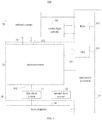
- a system 30 for controlling a laser projector 10 provided in an embodiment of the present disclosure includes a first drive circuit 31, a second drive circuit 32, a microprocessor 35 and an application processor 33.
- the first drive circuit 31 is coupled to the laser projector 10.
- the first drive circuit 31 is configured to output an electrical signal to drive the laser projector 10 to project laser light.
- the second drive circuit 32 is coupled to the first drive circuit 31.
- the second drive circuit 32 is configured to supply power to the first drive circuit 31.
- the microprocessor 35 is coupled to the first drive circuit 31.
- the application processor 33 is coupled to the microprocessor 35 and the second drive circuit 32.
- the application processor 33 is configured to, read a preset signal from the microprocessor 35, and power off the second drive circuit 32 to power off the first drive circuit 31 and the laser projector 10, and/or send a reset signal for restarting the microprocessor 35 to the microprocessor 35, in response to that the application processor 33 cannot read the preset signal.
- a mobile terminal 100 provided in an embodiment of the present disclosure includes a laser projector 10 and a system 30 for controlling the laser projector 10.
- the system 30 includes a first drive circuit 31, a second drive circuit 32, a microprocessor 35 and an application processor 33.
- the first drive circuit 31 is coupled to the laser projector 10.
- the first drive circuit 31 is configured to output an electrical signal to drive the laser projector 10 to project laser light.
- the second drive circuit 32 is coupled to the first drive circuit 31.
- the second drive circuit 32 is configured to supply power to the first drive circuit 31.
- the microprocessor 35 is coupled to the first drive circuit 31.
- the application processor 33 is coupled to the microprocessor 35 and the second drive circuit 32.
- the application processor 33 is configured to, read a preset signal from the microprocessor 35, and power off the second drive circuit 32 to power off the first drive circuit 31 and the laser projector 10, and/or send a reset signal for restarting the microprocessor 35 to the microprocessor 35, in response to that the application processor 33 cannot read the preset signal.
- the application processor 33 may determine that the microprocessor 35 is malfunctioning when the application processor 33 cannot read the preset signal from the microprocessor 35.
- the microprocessor 35 When the microprocessor 35 is malfunctioning, it indicates that the microprocessor 35 cannot control the laser projector 10 through the first drive circuit 31.
- the laser projector 10 may operate normally, which may continuously emit laser light outward to damage the user. Under this case, there may be various ways of controlling the laser projector 10 when the microprocessor 35 is malfunctioning as following.
- the application processor 33 may power off the second drive circuit 32 to power off the first drive circuit 31 and the laser projector 10. In other words, the application processor 33 may control the laser projector 10 to power off directly through the second drive circuit 32.
- the application processor 33 may send the reset signal for restarting the microprocessor 35 to the microprocessor 35.
- the malfunctioning microprocessor 35 may be restarted based on the reset signal, such that the microprocessor 35 operate normally.
- the operating normally microprocessor 35 may control the laser projector 10 through the first drive circuit 31, such that the laser projector 10 may operate normally.
- the application processor 33 may reset the microprocessor 35 to enable the microprocessor 35 to operate normally, so as to control the laser projector 10 to operate normally.
- the application processor 33 may power off the second drive circuit 32 to power off the first drive circuit 31 and the laser projector 10, and then send the reset signal for restarting the microprocessor 35 to the microprocessor 35.
- the application processor 33 may control the laser projector 10 to power off directly through the second drive circuit 32, and then reset the microprocessor 35 to operate normally to control the laser projector 10 to operate normally.
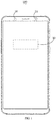
- a mobile terminal 100 provided in an embodiment of the present disclosure includes a laser projector 10, an infrared camera 20 and a system 30 for controlling the laser projector 10.
- the mobile terminal 100 may be a mobile phone, a tablet computer, a smart watch, a smart wristband, a smart wearable device, etc.
- an example of the mobile terminal 100 is the mobile phone, and the specific form of the mobile terminal 100 may be not limited to the mobile phone.
- the laser projector 10 is capable of projecting laser light to a target object.
- the laser light may be infrared light.
- the laser light projected by the laser projector 10 may be a pattern with specific speckles or streaks.
- the infrared camera 20 is capable of collecting an infrared image of the target object, or receiving a laser pattern modulated by the target object.
- it is usually necessary to continuously emit a plurality of frames of laser light to the target object with a certain optical power.
- the laser projector 10 continuously emits laser light outward, the laser light may burn the user, especially to the user's eyes. Therefore, it is necessary to prevent the laser projector 10 from continuously emitting laser light outward.
- the system 30 includes a first drive circuit 31, a second drive circuit 32, an application processor 33 and a microprocessor 35.
- the first drive circuit 31 is coupled to the laser projector 10.
- the first drive circuit 31 is configured to output an electrical signal to the laser projector 10, to drive the laser projector 10 to project laser light.
- the first drive circuit 31 serves as a current source of the laser projector 10. If the first drive circuit 31 is powered off, the laser projector 10 cannot emit laser light outward; or, the first drive circuit 31 stops outputting the electric signal to the laser projector 10, the laser projector 10 cannot emit laser light outward.
- the second drive circuit 32 is coupled to the first drive circuit 31.
- the second drive circuit 32 is configured to supply power to the first drive circuit 31.
- the first drive circuit 31 may be a DC/DC circuit.
- the first drive circuit 31 may be separately packaged as a drive chip, and the second drive circuit 32 may be separately packaged as a drive chip, or the first drive circuit 31 and the second drive circuit 32 may be packaged together in one drive chip.
- the drive chips all may be disposed on a substrate or a circuit board of the laser projector 10.
- the microprocessor 35 is coupled to the first drive circuit 31 and the infrared camera 20.
- the microprocessor 35 may be a processing chip.
- the microprocessor 35 may be coupled to the first drive circuit 31 through a Pulse Width Modulation (PWM) interface 352.
- PWM Pulse Width Modulation
- the microprocessor 35 may be coupled to the infrared camera 20 through an Inter-Integrated Circuit (I2C) bus 70.
- I2C Inter-Integrated Circuit
- the microprocessor 35 may provide the infrared camera 20 with clock information for collecting infrared images and laser patterns.
- the infrared images and laser patterns collected by the infrared camera 20 may be sent to the microprocessor 35 through a Mobile Industry Processor Interface (MIPI) 351.
- MIPI Mobile Industry Processor Interface
- the application processor 33 may server as a system of the mobile terminal 100.
- the application processor 33 is coupled to the microprocessor 35 and the second drive circuit 32.
- the application processor 33 may also be coupled to the infrared camera 20 and a visible light camera 50.
- the microprocessor 35 is coupled to the application processor 33 to enable the application processor 33 to reset the microprocessor 35, wake up the microprocessor 35, debug the microprocessor 35, etc.
- the microprocessor 35 may be coupled to the application processor 33 through the MIPI 351.
- the microprocessor 35 is coupled to a Trusted Execution Environment (TEE) 331 of the application processor 33 through the MIPI 351, to transfer data in the microprocessor 35 directly to the TEE 331.
- TEE Trusted Execution Environment
- the code and the memory area in the TEE 331 are both controlled by an access control unit and cannot be accessed by the program in the Rich Execution Environment (REE) 332.
- the TEE 331 and the REE 332 may all be
- an infrared template and a depth template for verifying an identity may be stored in the TEE 331.
- the infrared template may be a face infrared image input by the user in advance.
- the depth template may be a face depth image input by the user in advance.
- the infrared template and the depth template are stored in the TEE 331, which are not easily falsified and stolen, such that the information in the mobile terminal 100 is relatively secure.
- the microprocessor 35 controls the infrared camera 20 to collect an infrared image of the user, and sends the collected infrared image to the TEE 331 of the application processor 33.
- the collected infrared image is compared with the infrared template in the TEE 331 by the application processor 33. If the two matches, a result that the verification based on the infrared template passes is output. In the process of matching whether the infrared image and the infrared template, the infrared image and the infrared template cannot be obtained, falsified or stolen by other programs, thereby improving the information security of the mobile terminal 100.
- the microprocessor 35 may control the first drive circuit 31 to drive the laser projector 10 to project laser light outward, and control the infrared camera 20 to collect the laser pattern modulated by the target object.
- the microprocessor 35 obtains and processes the laser pattern to get a depth image.
- the depth image is sent to the TEE 331 of the application processor 33.
- the application processor 33 compares the depth image with the depth template in the TEE 331. If the two matches, a result that the verification based on the depth template passes is output. In the process of matching whether the depth image and the depth template, the depth image and the depth template cannot be obtained, falsified or stolen by other programs, thereby improving the information security of the mobile terminal 100.
- the application processor 33 may also be coupled to a plurality of electronic components of the mobile terminal 100 and control the plurality of electronic components to operate in predetermined modes. For example, a display screen of the mobile terminal 100 is controlled to display predetermined frames, an antenna of the mobile terminal 100 is controlled to transmit or receive predetermined data, the visible light camera 50 of the mobile terminal 100 is controlled to obtain a color image and to process the color image, the power of the infrared camera 20 is controlled to power on or off, the infrared camera 20 is controlled to power down or to reset, and the like.
- the first drive circuit 31 may be in a state of continuously driving the laser projector 10 to emit laser light outward, and the laser light emitted continuously outward has the higher danger. Therefore, it is necessary to monitor an operating state of the microprocessor 35.
- system 30 may read the preset signal from the microprocessor 35 through the application processor 33 to determine the operating state of the microprocessor 35.
- the system 30 may periodically read the preset signal from the microprocessor 35 through the application processor 33 to determine the operating state of the microprocessor 35.
- the period of reading the preset signal from the microprocessor 35 through the application processor 33 may be from 1 millisecond to 100 milliseconds.
- the period of reading the preset signal from the microprocessor 35 through the application processor 33 may be 1 millisecond, 5 milliseconds, 10 milliseconds, 15 milliseconds, 20 milliseconds. 25 milliseconds, 30 milliseconds, 40 milliseconds, 50 milliseconds, 60 milliseconds, 70 milliseconds, 80 milliseconds, 90 milliseconds, or 100 milliseconds.
- the application processor 33 is configured to, read the preset signal from the microprocessor periodically, and power off the second drive circuit to power off the first drive circuit and the laser projector, and/or send the reset signal for restarting the microprocessor to the microprocessor, in response to that the application processor cannot read the preset signal continuously for a plurality of times.
- the preset signal includes a flag signal of the microprocessor 35, and a flag signal of the infrared camera 20 and read by the microprocessor 35.
- the flag signal of the microprocessor 35 includes a series of processor-related information, such as a type, a model, manufacturer information, trademark information, a serial number, and cache of the microprocessor 35.
- the flag signal of the infrared camera 20 includes a series of camera-related information, such as a type, a model, manufacturer information, trademark information, a serial number, and cache of the infrared camera 20.
- the application processor 33 may read the preset signal from the microprocessor 35 only when the laser projector 10 is needed. The case where the laser projector 10 is needed includes the user using the laser projector 10 to perform 3D face recognition.
- the application processor 33 When the application processor 33 cannot read (or continuously cannot read for a plurality of times) the preset signal from the microprocessor 35, it indicates that the microprocessor 35 is in a down state. That is, the microprocessor 35 is malfunctioning. When the application processor 33 can read (or continuously cannot read for a plurality of times) the preset signal from the microprocessor 35, it indicates that the microprocessor 35 is in a normal state. That is, the microprocessor 35 may operate normally.
- the number of the plurality of times may be set in advance, which is not limited here.
- the application processor 33 when the application processor 33 cannot continuously read the preset signal for a plurality of times from the microprocessor 35, it indicates that the microprocessor 35 is in the down state (i.e., the microprocessor 35 is malfunctioning). Under this case, there may be various ways of controlling the laser projector 10 when the microprocessor 35 is malfunctioning, which may refer to the embodiments described above, and be not repeated here.
- the application processor 33 periodically reads the preset signal from the microprocessor 35.
- the application processor 33 is configured to detect whether the laser projector 10 is powered on (whether the laser projector 10 is in a state of emitting laser light) in response to that the application processor 33 cannot read the preset signal continuously for a plurality of times.
- the application processor 33 is configured to power off the second drive circuit 32 to power off the first drive circuit 31 and the laser projector 10, and to send the reset signal for restarting the microprocessor 35, in response to that the laser projector 10 is powered on.
- the application processor 33 is configured to send the reset signal for restarting the microprocessor 35 in response to that the laser projector 10 is powered off.
- the laser projector 10 is also directly coupled to the application processor 33 to enable the application processor 33 to detect whether the laser projector 10 is operating (in a state in which laser light is emitted).
- the application processor 33 may determine whether the laser projector 10 is operating by detecting a flag signal of the laser projector 10.
- the flag signal of the laser projector 10 includes information related to the laser projector, such as a type, a model, manufacturer information, trademark information, a serial number, and cache of the laser projector 10.
- the system 30 provided in the present embodiment first powers off the laser projector 10 and then restarts the microprocessor 35 when the microprocessor 35 is malfunctioning and the laser projector 10 is powered on, to prevent the laser projector 10 from being a state of emitting laser light for a long period of time, thereby preventing the laser projector 10 from continuously emitting laser light outward to damage the user.
- the application processor 33 is configured to, after sending the reset signal for restarting the microprocessor 35 to the microprocessor 35, read the preset signal from the microprocessor 35, and power off the second drive circuit 32 to power off the first drive circuit 31 and the laser projector 10 in response to that the application processor 33 cannot read the preset signal.
- the application processor 33 after the application processor 33 sends the reset signal for restarting the microprocessor 35 to the microprocessor 35, the application processor 33 cannot read the preset signal from the microprocessor 35, it indicates that the microprocessor 35 may be damaged. At this time, the microprocessor 35 cannot be restarted to make it operate normally.
- the application processor 33 After the application processor 33 sends the reset signal for restarting the microprocessor 35 to the microprocessor 35, the application processor 33 cannot read the preset signal from the microprocessor 35, the application processor 33 powers off the second drive circuit 32 to power off the first drive circuit 31 and the laser projector 10, thereby preventing the laser projector 10 from continuously emitting laser light outward to damage the user.
- the system 30 further includes a watchdog timer 34 coupled to the first drive circuit 31 and the application processor 33.
- the application processor 33 is further configured to send a predetermined signal to the watchdog timer 34 at a predetermined time interval.
- the watchdog timer 34 is configured to, receive the predetermined signal, and power off the first drive circuit 31 to power off the laser projector 10 in response to that the predetermined signal is not received during a predetermined duration.
- the predetermined signal may include a signal indicating an operating state of the application processor 33.
- the watchdog timer 34 may determine whether the application processor 33 has an operation failure according to the predetermined signal.
- the predetermined signal may further include a signal controlling the first drive circuit 31 and the laser projector 10 to operate.
- the watchdog timer 34 may control the intensity, time, and the like of the laser light emitted from the laser projector 10 in accordance with the predetermined signal. Since the application processor 33 is in an operation failure state, for example, when the application processor 33 is down, if the first drive circuit 31 may be in a state of continuously driving the laser projector 10 to emit laser light, the laser projector 10 may emit laser light to damage the user.
- the watchdog timer 34 may power off the laser projector 10 by powering off the first drive circuit 31.
- the system 30 provided in the present embodiment may send the predetermined signal to the watchdog timer 34 through the application processor 33 at a predetermined time interval, for example, send a clear signal (predetermined signal) to the watchdog timer 34 every 50 milliseconds.
- the application processor 33 cannot run the program for sending the predetermined signal to the watchdog timer 34, such that the predetermined signal cannot be sent to make the failure state of the application processor 33 to be detected.
- the watchdog timer 34 is configured to power off the first drive circuit 31 to power off the laser projector 10 when the predetermined signal is not received within the predetermined duration.
- the predetermined duration may be set when the mobile terminal 100 leaves factory, or may be customized according to the user of the mobile terminal 100.
- a specific form of the watchdog timer 34 may be a counter. After the watchdog timer 34 receives the predetermined signal, the watchdog timer 34 starts counting down from a number at a certain speed. If the application processor 33 is operating normally, the application processor 33 will resend the predetermined signal before the number is counted down to 0. The watchdog timer 34 resets the number for counting down again after receiving the predetermined signal. If the application processor 33 is not operating normally, the watchdog timer 34 count down the number to 0, and is deemed to determine that the application processor 33 is malfunctioning. At the same time, the watchdog timer 34 sends the signal to power off the first drive circuit 31 to power off the laser projector 10.
- the watchdog timer 34 may be external to the application processor 33.
- the watchdog timer 34 may be an external timer chip.
- the watchdog timer 34 may be coupled to an I/O of the application processor 33 to receive the predetermined signal from the application processor 33.
- the reliability of the external watchdog timer 34 is high.
- the watchdog timer 34 may be integrated within the application processor 33, and the functionality of the watchdog timer 34 may be implemented by an internal timer of the application processor 33, which simplifies a hardware circuit design of the system 30.
- the system 30 further includes a watchdog timer 34 coupled to the first drive circuit 31 and the application processor 33.
- the application processor 33 is further configured to send a predetermined signal to the watchdog timer 34 at a predetermined time interval.
- the watchdog timer 34 is configured to, receive the predetermined signal from the application processor 33 and send the reset signal for restarting the application processor 33 in response to that the predetermined signal is not received during a predetermined duration.
- the watchdog timer 34 when the watchdog timer 34 does not receive the predetermined signal within the predetermined duration, the application processor 33 is malfunctioning. At this time the watchdog timer 34 sends the reset signal to cause the application processor 33 to reset and operate normally.
- the reset signal may be directly received by the application processor 33.
- the reset signal has a higher level in the execution program of the application processor 33.
- the application processor 33 may preferentially respond to the reset signal.
- the reset signal may also be sent to a reset chip external to the application processor 33. The reset chip responds to the reset signal to force the application processor 33 to reset.
- the system 30 further includes a watchdog timer 34 coupled to the first drive circuit 31 and the application processor 33.
- the application processor 33 is further configured to send a predetermined signal to the watchdog timer 34 at a predetermined time interval.
- the watchdog timer 34 is configured to, receive the predetermined signal from the application processor 33, power off the first drive circuit 31 to power off the laser projector 10 and send the reset signal for restarting the application processor 33 in response to that the predetermined signal is not received during a predetermined duration.
- the watchdog timer 34 may first power off the first drive circuit 31 to power off the laser projector 10, and then send the reset signal to cause the application processor 33 to reset and operate normally.
- the system 30 further includes a watchdog timer 34 coupled to the first drive circuit 31 and the application processor 33.
- the application processor 33 is further configured to send a predetermined signal to the watchdog timer 34 at a predetermined time interval.
- the watchdog timer 34 is configured to, receive the predetermined signal from the application processor 33.
- the first drive circuit 31 is further configured to send a timeout signal to the application processor 33 (at this time, the application processor 33 is also directly coupled to the first drive circuit 31) in response to that a duration of outputting the electrical signal is greater than or equal to a predetermined threshold.
- the application processor 33 is configured to stop sending the predetermined signal to the watchdog timer 34 upon receiving the timeout signal.
- the watchdog timer 34 is also configured to power off the first drive circuit 31 to power off the laser projector 10 when the predetermined signal is not received within the predetermined duration.
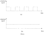
- the first drive circuit 31 when the first drive circuit 31 operates normally, the first drive circuit 31 outputs a pulse wave signal (for example, a square wave signal), such that the laser projector 10 continuously emits a plurality of frames of laser light.
- a pulse wave signal for example, a square wave signal
- the first drive circuit 31 when the first drive circuit 31 is malfunctioning, the first drive circuit 31 will keep outputting a high-level signal, such that the laser projector 10 continuously emits laser light outward.
- the laser projector 10 may be powered off by powering off the first drive circuit 31.
- the first drive circuit 31 may be integrated with a timing function.
- the first drive circuit 31 may detect itself whether a duration of outputting the electrical signal is greater than or equal to a predetermined threshold.
- the first drive circuit 31 stops outputting the electrical signal to power off the laser projector 10.
- the predetermined threshold may be within a range of [3, 10] milliseconds.
- the predetermined threshold may be set to 3 milliseconds, 4 milliseconds, 5 milliseconds, 6 milliseconds, 7 milliseconds, 8 milliseconds, 9 milliseconds, 10 milliseconds and any milliseconds within the above range.
- the first drive circuit 31 may send the timeout signal to the application processor 33.
- the application processor 33 receives the timeout signal from the first drive circuit 31, the application processor 33 stops sending the predetermined signal to the watchdog timer 34.
- the watchdog timer 34 is coupled to the first drive circuit 31.
- the watchdog timer 34 is coupled to the application processor 33.
- the watchdog timer 34 is configured to power off the first drive circuit 31 to power off the laser projector 10 when the predetermined signal is not received within the predetermined duration.
- the predetermined duration may be set when the mobile terminal 100 leaves factory, or may be customized according to the user of the mobile terminal 100.
- the specific form of the watchdog timer 34 may be a counter. After the watchdog timer 34 receives the predetermined signal, the watchdog timer 34 starts counting down at a certain speed from a number. If the first drive circuit 31 normally outputs the pulse wave signal, the application processor 33 resends the predetermined signal before the number is counted down to reach 0, and the watchdog timer 34 resets the number after receiving the predetermined signal. If the duration of outputting the electrical signal by the first drive circuit 31 is greater than or equal to the predetermined threshold, and the watchdog timer 34 counts to 0, the application processor 33 does not send the predetermined signal, and the watchdog timer 34 is deemed to determine that the first drive circuit 31 is malfunctioning. A signal is sent by the watchdog timer 34 to power off the first drive circuit 31 to power off the laser projector 10.
- the predetermined duration of the above embodiment is within a range of [50, 150] milliseconds.
- the predetermined duration may be set to 50 milliseconds, 62 milliseconds, 75 milliseconds, 97 milliseconds, 125 milliseconds, 150 milliseconds and any duration within the above range. It should be understood that if the predetermined duration is set too short, the application processor 33 is required to send the predetermined signal too frequently, which may occupy too much processing space of the application processor 33 and cause the mobile terminal 100 to jam easily. If the predetermined duration is set too long, the failure of the application processor 33 cannot be detected in time, that is, the laser projector 10 cannot be powered off in time, which is disadvantageous for the safe use of the laser projector 10. By setting the predetermined duration within a range of [50, 150] milliseconds, it is possible to better balance the fluency and security of the mobile terminal 100.
- the system 30 further includes a watchdog timer 34 coupled to the first drive circuit 31 and the microprocessor 33.
- the microprocessor 33 is configured to send a predetermined signal to the watchdog timer 34 at a predetermined time interval.
- the microprocessor 35 may send a clear signal (the predetermined signal) to the watchdog timer 34 every 50 milliseconds.
- the watchdog timer 34 is configured to receive the predetermined signal from the microprocessor 35 and power off the first drive circuit 31 to power off the laser projector 10 in response to that the predetermined signal is not received during a predetermined duration.
- the predetermined signal may include a signal indicating an operating state of the microprocessor 35.
- the watchdog timer 34 may determine whether the microprocessor 35 has an operation failure according to the predetermined signal.
- the predetermined signal may further include a signal for controlling the first drive circuit 31 and the laser projector 10 to operate.
- the watchdog timer 34 may control the intensity, time, and the like of the laser light emitted by the laser projector 10 in accordance with the predetermined signal.
- the first drive circuit 31 sends a timeout signal to the microprocessor 35.
- the microprocessor 35 When the microprocessor 35 receives the timeout signal from the first drive circuit 31, the microprocessor 35 stops sending the predetermined signal.
- the watchdog timer 34 is coupled to the first drive circuit 31.
- the watchdog timer 34 is coupled to the microprocessor 35.
- the watchdog timer 34 is configured to power off the first drive circuit 31 to power off the laser projector 10 when the predetermined signal is not received within the predetermined duration.
- the first drive circuit 31 stops outputting the electrical signal to the laser projector 10 to power off the laser projector 10.
- the predetermined duration may be set when the mobile terminal 100 leaves factory, or may be customized according to the user of the mobile terminal 100.
- the specific form of the watchdog timer 34 may be a counter. After the watchdog timer 34 receives the predetermined signal, the watchdog timer 34 starts counting down at a certain speed from a number. If the first drive circuit 31 normally outputs the pulse wave signal, the microprocessor 35 resend the predetermined signal before the number is counted down to reach 0, the watchdog timer 34 resets the number upon receiving the predetermined signal. If the duration of outputting the electrical signal by the first drive circuit 31 is greater than or equal to a predetermined threshold, and the watchdog timer 34 count the number down to 0, the microprocessor 35 does not send the predetermined signal, the watchdog timer 34 determined that the first drive circuit 31 is malfunctioning. A signal is sent by the watchdog timer 34 to power off the first drive circuit 31 to power off the laser projector 10.
- the watchdog timer 34 may be external to the microprocessor 35.
- the watchdog timer 34 may be an external timer chip.
- the watchdog timer 34 may be coupled to an I/O of the microprocessor 35 to receive the predetermined signal from the microprocessor 35.
- the reliability of the external watchdog timer 34 is high.
- the watchdog timer 34 may be integrated into the microprocessor 35.
- the function of the watchdog timer 34 may be implemented by an internal timer of the microprocessor 35, which simplifies a hardware circuit design of the system 30.
- the system 30 further includes a watchdog timer 34 coupled to the first drive circuit 31 and the microprocessor 33.
- the microprocessor 33 is configured to send a predetermined signal to the watchdog timer 34 at a predetermined time interval.
- the watchdog timer 34 is configured to receive the predetermined signal from the microprocessor 35.
- the first drive circuit 31 is configured to send a timeout signal to the microprocessor 35 in response to that a duration of outputting the electrical signal is greater than or equal to a predetermined threshold.
- the microprocessor 35 is configured to stop sending the predetermined signal to the watchdog timer 34 upon receiving the timeout signal.
- the watchdog timer 34 is configured to power off the laser projector 10 in response to that the predetermined signal is not received during a predetermined duration.
- the first drive circuit 31 may send the timeout signal to the microprocessor 35.
- the microprocessor 35 receives the timeout signal from the first drive circuit 31, the microprocessor 35 stops sending the predetermined signal to the watchdog timer 34.
- the watchdog timer 34 is coupled to the first drive circuit 31.
- the watchdog timer 34 is coupled to the microprocessor 35.
- the watchdog timer 34 is configured to power off the first drive circuit 31 to power off the laser projector 10 when the predetermined signal is not received within the predetermined duration.
- the specific form of the watchdog timer 34 may be a counter. After the watchdog timer 34 receives the predetermined signal, the watchdog timer 34 starts counting down at a certain speed from a number. If the first drive circuit 31 normally outputs the pulse wave signal, the microprocessor 35 resends the predetermined signal before the number is counted down to reach 0, and the watchdog timer 34 resets the number after receiving the predetermined signal. If the duration of outputting the electrical signal by the first drive circuit 31 is greater than or equal to the predetermined threshold, and the watchdog timer 34 counts to 0, the microprocessor 35 does not send the predetermined signal, and the watchdog timer 34 is deemed to determine that the first drive circuit 31 is malfunctioning. A signal is sent by the watchdog timer 34 to power off the first drive circuit 31 to power off the laser projector 10.
- the predetermined duration of the above embodiment is within a range of [50, 150] milliseconds.
- the predetermined duration may be set to 50 milliseconds, 62 milliseconds, 75 milliseconds, 97 milliseconds, 125 milliseconds, 150 milliseconds and any duration within the above range. It should be understood that if the predetermined duration is set too short, the microprocessor 35 is required to send the predetermined signal too frequently, which may occupy too much processing space of the microprocessor 35 and cause the mobile terminal 100 to jam easily.
- the predetermined duration is set too long, the failure of the microprocessor 35 cannot be detected in time, that is, the laser projector 10 cannot be powered off in time, which is disadvantageous for the safe use of the laser projector 10.
- the predetermined duration within a range of [50, 150] milliseconds, it is possible to better balance the fluency and security of the mobile terminal 100.
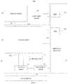
- the system 30 further includes a control circuit 36.
- the control circuit 36 is coupled to the first drive circuit 31 and the laser projector 10.
- the control circuit 36 includes a resistance element 361, a detecting element 362 and a switching element 363.
- the detecting element 362 may be an ammeter.
- the detecting element 362 is coupled with the resistance element 361 and the first drive circuit 31 in series.
- the detecting element 362 is configured to detect a current flowing through the resistance element 361.
- the switching element 363 is coupled to the laser projector 10.
- the switching element 363 is configured to switch off the laser projector 10 when the current flowing through the resistance element 361 is greater than a preset current value.
- the first drive circuit 31 when the first drive circuit 31 outputs an electrical signal to drive the laser projector 10 to project each frame of laser light, and the current output by the first drive circuit 31 is sequentially increased. For example, the current output by the first drive circuit 31 is increased from 100 mAto 200 mA.
- the first drive circuit 31 keeps outputting a high-level signal, and the current may be increased continuously after increasing from 100 mA to 200 mA.
- the preset current value may be set to 220mA Since the resistance element 361 is coupled in series with the first drive circuit 31, the current flowing through the first drive circuit 31 is the current flowing through the resistance element 361.
- the switching element 363 is switched off when the current flowing through the resistance element 361 is greater than 220 mA to power off the laser projector 10.
- the detecting element 362 may be a voltmeter.
- the detecting element 362 may be coupled to the resistance element 361 in parallel.
- the detecting element 362 is configured to detect a voltage across the resistance element 361.
- the switching element 363 is switched off to power off the laser projector 10 when the voltage across the resistance element 361 is greater than a preset voltage value, which is not described in detail here.
- a laser projection assembly 60 is provided.
- the laser projection assembly 60 includes a laser projector 10, a first drive circuit 31, and a second drive circuit 32.
- the first drive circuit 31 and the second drive circuit 32 both may be integrated into a substrate assembly 11 of the laser projector 10.
- the laser projector 10 includes a substrate assembly 11, a lens barrel 12, a light source 13, a collimating element 14, a diffractive optical element (DOE) 15, and a protective cover 16.
- DOE diffractive optical element
- the substrate assembly 11 includes a substrate 111 and a circuit board 112.
- the circuit board 112 is disposed on the substrate 111.
- the circuit board 112 is configured to couple the e light source 13 and a main board of the mobile terminal 100.
- the circuit board 112 may be a hard board, a soft board or a soft and hard board.
- a through hole 1121 is formed in the circuit board 112.
- the light source 13 is fixed on the substrate 111 and electrically coupled to the circuit board 112.
- a heat dissipation hole 1111 may be formed on the substrate 111.
- the heat generated by the operation of the light source 13 or the circuit board 112 may be dissipated by the heat dissipation hole 1111.
- the heat dissipation hole 111 may be filled with a thermal adhesive, to further improve the heat dissipation performance of the substrate assembly 11.
- the lens barrel 12 is fixedly coupled to the substrate assembly 11.
- the lens barrel 12 is formed with an accommodating cavity 121.
- the lens barrel 12 includes a top wall 122 and an annular peripheral wall 124 extending from the top wall 122.
- the peripheral wall 124 is disposed on the substrate assembly 11.
- the top wall 122 defines a light-passing hole 1212 communicating with the accommodating cavity 121.
- the peripheral wall 124 may be coupled to the circuit board 112 by glue.
- the protective cover 16 is disposed on the top wall 122.
- the protective cover 16 includes a baffle 162 having a light-passing hole 160 and an annular side wall 164 extending from the baffle 162.
- the light source 13 and the collimating element 14 are both disposed in the accommodating cavity 121.
- the diffractive optical element 15 is mounted on the lens barrel 12.
- the collimating element 14 and the diffractive optical element 15 are sequentially disposed on a light-emitting path of the light source 13.
- the collimating element 14 collimates the laser light emitted by the light source 13, and the laser light passes through the collimating element 14 and then passes through the diffractive optical element 15 to form a laser pattern.
- the light source 13 may be a Vertical Cavity Surface Emitting Laser (VCSEL) or an edge-emitting laser (EEL). In the embodiment illustrated in FIG. 9 , the light source 13 is an edge-emitting laser. In detail, the light source 13 may be a Distributed Feedback Laser (DFB).
- the light source 13 is configured to emit laser light into the accommodating cavity 112. Referring to FIG. 10 , the light source 13 is a columnar as a whole. One end surface of the light source 13, which is away from the substrate assembly 11, form a light-emitting surface 131. The laser light is emitted from the light-emitting surface 131. The light-emitting surface 131 faces the collimating element 14.
- the light source 13 is fixed on the substrate assembly 11.
- the light source 13 may be adhered to the substrate assembly 11 by a sealant 17.
- a surface of the light source 13 opposite to the light-emitting surface 131 is attached to the substrate assembly 11.
- one or more side surfaces 132 of the light source 13 may also be adhered to the substrate assembly 11.
- the sealing 17 encloses the surrounding side surfaces 132, or may only attach one side surface 132 to the substrate assembly 11, or a few side surfaces 132 to the substrate assembly 11.
- the sealant 17 may be a thermal conductive adhesive to conduct heat generated by the operation of the light source 13 into the substrate assembly 11.
- the diffractive optical element 15 is carried on the top wall 122 and housed in the protective cover 16. The opposite sides of the diffractive optical element 15 are respectively in contact with the protective cover 16 and the top wall 122.
- the baffle 162 includes an abutting surface 1622 adjacent to the light-passing hole 1212, and the diffractive optical element 15 is in contact with the abutting surface 1622.
- the diffractive optical element 15 includes a diffraction incident surface 152 and a diffraction exit surface 154 which are opposite.
- the diffractive optical element 15 is carried on the top wall 122.
- the diffractive exit surface 154 is in contact with the surface (the abutting surface 1622) of the baffle 162 near the light-passing hole 1212, and the diffractive incident surface 152 is in contact with the top wall 162.
- the light-passing hole 1212 is aligned with the accommodating cavity 121.
- the light-emitting through-hole 160 is aligned with the light-passing hole 1212.
- the top wall 122, the annular side wall 164, and the baffle 162 are in contact with the diffractive optical element 15, thereby preventing the diffractive optical element 15 from falling out of the protective cover 16 in the light emission direction.
- the protective cover 16 is adhered to the top wall 162 by glue.
- the light source 13 of the laser projector 10 described above employs an edge-emitting laser.
- the temperature drift of the edge-emitting laser is smaller than that of the VCSEL array.
- the edge-emitting laser is a single-point emitting structure, it is not necessary to design an array structure. The manufacturing is simple, and the light source of the laser projector 10 is low in cost.
- the distributed feedback laser When the laser light of the distributed feedback laser propagates, the gain of the power is obtained through the feedback of the grating structure.
- the light-emitting surface 131 of the edge-emitting laser faces the collimating element 14, the edge-emitting laser is placed vertically.
- the edge-emitting laser Due to the structure of elongate strip of the edge-emitting laser, the edge-emitting laser is prone to accidents such as dropping, shifting or shaking. Therefore, by providing the sealant 17, the edge-emitting laser may be fixed to prevent accidents such as dropping, displacement or shaking of the edge-emitting laser.
- the light source 13 may also be fixed to the substrate assembly 11 in a fixed manner as illustrated in FIG. 12 .
- the laser projector 10 includes a plurality of support members 18.
- the plurality of support members 18 may be fixed to the substrate assembly 11.
- the plurality of support members 18 collectively surround the light source 13.
- the light source 13 may be directly mounted among the plurality of support members 18.
- the plurality of support members 18 collectively clamp the light source 13 to further prevent the light source 13 from shaking.
- the protective cover 16 may be omitted.
- the diffractive optical element 15 may be disposed in the accommodating cavity 121.
- the diffraction exit surface 154 of the diffractive optical element 15 may be opposed to the top wall 122, and the laser light passes through the diffractive optical element 15 and then passes through the light-passing hole 1212. Thus, the diffractive optical element 15 is less likely to fall off.
- the substrate 111 may also be omitted.
- the light source 13 may be directly fixed to the circuit board 112 to reduce the thickness of the laser projector 10.
- first and second are used herein for purposes of description and are not intended to indicate or imply relative importance or significance.
- the feature defined with “first” and “second” may comprise one or more this feature.
- a plurality of' means two or more than two, unless specified otherwise.
Landscapes
- Physics & Mathematics (AREA)
- Engineering & Computer Science (AREA)
- General Physics & Mathematics (AREA)
- Theoretical Computer Science (AREA)
- Optics & Photonics (AREA)
- Signal Processing (AREA)
- Computer Hardware Design (AREA)
- Electromagnetism (AREA)
- General Engineering & Computer Science (AREA)
- Condensed Matter Physics & Semiconductors (AREA)
- Multimedia (AREA)
- Automation & Control Theory (AREA)
- Human Computer Interaction (AREA)
- Semiconductor Lasers (AREA)
- Projection Apparatus (AREA)
Applications Claiming Priority (2)
| Application Number | Priority Date | Filing Date | Title |
|---|---|---|---|
| CN201810539478.XA CN108717280B (zh) | 2018-05-30 | 2018-05-30 | 激光投射器的控制系统和移动终端 |
| CN201810539345.2A CN108539575B (zh) | 2018-05-30 | 2018-05-30 | 激光投射器的控制系统和移动终端 |
Publications (3)
| Publication Number | Publication Date |
|---|---|
| EP3584672A2 true EP3584672A2 (de) | 2019-12-25 |
| EP3584672A3 EP3584672A3 (de) | 2020-03-04 |
| EP3584672B1 EP3584672B1 (de) | 2022-02-09 |
Family
ID=66676316
Family Applications (1)
| Application Number | Title | Priority Date | Filing Date |
|---|---|---|---|
| EP19177180.7A Active EP3584672B1 (de) | 2018-05-30 | 2019-05-29 | Systeme zur steuerung eines laserprojektors und von mobilen endgeräten |
Country Status (3)
| Country | Link |
|---|---|
| US (1) | US11300865B2 (de) |
| EP (1) | EP3584672B1 (de) |
| WO (1) | WO2019228020A1 (de) |
Families Citing this family (2)
| Publication number | Priority date | Publication date | Assignee | Title |
|---|---|---|---|---|
| EP3633546A4 (de) * | 2018-04-12 | 2020-10-21 | Guangdong Oppo Mobile Telecommunications Corp., Ltd. | Bildverarbeitungsverfahren und -vorrichtung sowie elektronische vorrichtung und computerlesbares speichermedium |
| EP3611810B1 (de) * | 2018-04-28 | 2021-06-02 | Guangdong Oppo Mobile Telecommunications Corp., Ltd. | Steuerungssystem und steuerungsverfahren für laserprojektor, laserprojektionsanordnung und endgerät |
Family Cites Families (26)
| Publication number | Priority date | Publication date | Assignee | Title |
|---|---|---|---|---|
| US5298750A (en) | 1992-01-15 | 1994-03-29 | Rericha Frank M | Laser precipitation sensor |
| WO2001015289A2 (en) | 1999-08-09 | 2001-03-01 | Perceptron, Inc. | Method and system for maximizing safe laser power of structured laser light projectors |
| JP3616367B2 (ja) * | 2001-10-24 | 2005-02-02 | 三菱電機株式会社 | 電子制御装置 |
| CN2537509Y (zh) | 2002-05-14 | 2003-02-26 | 湖北光通光电系统有限公司 | 具有防爆保护功能的激光标记机 |
| US7515619B2 (en) | 2005-06-22 | 2009-04-07 | Intel Corporation | Laser control circuit |
| JP2010510766A (ja) | 2006-11-21 | 2010-04-02 | パワービーム インコーポレイテッド | 電気的にパワー供給される装置への光学的パワービーミング |
| US7774648B2 (en) | 2007-05-02 | 2010-08-10 | Honeywell International Inc. | Microprocessor supervision in a special purpose computer system |
| CN101409589B (zh) * | 2007-10-08 | 2011-04-20 | 深圳新飞通光电子技术有限公司 | 一种激光器驱动电路 |
| CN101650520A (zh) | 2008-08-15 | 2010-02-17 | 索尼爱立信移动通讯有限公司 | 移动电话的可视激光触摸板和方法 |
| US9265576B2 (en) * | 2010-02-21 | 2016-02-23 | C Laser, Inc. | Laser generator for medical treatment |
| JP5073796B2 (ja) | 2010-08-23 | 2012-11-14 | ファナック株式会社 | レーザ発振器制御装置 |
| US8634848B1 (en) | 2010-09-29 | 2014-01-21 | Amazon Technologies, Inc. | Inter-device location determinations |
| JP2013250407A (ja) | 2012-05-31 | 2013-12-12 | Panasonic Corp | 照射制御装置および照射制御方法 |
| CN106452599B (zh) * | 2013-05-08 | 2019-01-29 | 青岛海信宽带多媒体技术有限公司 | 一种光模块及光模块的控制方法 |
| CN203366017U (zh) | 2013-05-24 | 2013-12-25 | 海尔集团公司 | 一种楼宇对讲智能终端及其死机重启系统 |
| US20160125180A1 (en) | 2013-12-12 | 2016-05-05 | Intel Corporation | Near Field Communication Authentication Mechanism |
| US9753060B2 (en) | 2015-08-28 | 2017-09-05 | Stmicroelectronics (Research & Development) Limited | Apparatus with device with fault detection protection |
| CN105425661A (zh) | 2015-11-06 | 2016-03-23 | 厦门市智联信通物联网科技有限公司 | 激光定位灯的智能驱动控制方法、装置及补光灯控制器 |
| CN105786657A (zh) | 2016-03-25 | 2016-07-20 | 宇龙计算机通信科技(深圳)有限公司 | 一种终端死机处理方法及终端 |
| US10963044B2 (en) | 2016-09-30 | 2021-03-30 | Intel Corporation | Apparatus, system and method for dynamic modification of a graphical user interface |
| CN106454287B (zh) * | 2016-10-27 | 2018-10-23 | 深圳奥比中光科技有限公司 | 组合摄像系统、移动终端及图像处理方法 |
| US10355450B2 (en) * | 2016-11-10 | 2019-07-16 | Intel Corporation | System and method of reducing speckle for an illuminator |
| CN206832993U (zh) | 2017-04-10 | 2018-01-02 | 侯博超 | 便携式激光测高仪 |
| CN107424187B (zh) | 2017-04-17 | 2023-10-24 | 奥比中光科技集团股份有限公司 | 深度计算处理器、数据处理方法以及3d图像设备 |
| CN108717280B (zh) * | 2018-05-30 | 2021-04-02 | Oppo广东移动通信有限公司 | 激光投射器的控制系统和移动终端 |
| CN108539575B (zh) * | 2018-05-30 | 2021-04-02 | Oppo广东移动通信有限公司 | 激光投射器的控制系统和移动终端 |
-
2019
- 2019-03-11 WO PCT/CN2019/077705 patent/WO2019228020A1/zh not_active Ceased
- 2019-05-23 US US16/421,043 patent/US11300865B2/en active Active
- 2019-05-29 EP EP19177180.7A patent/EP3584672B1/de active Active
Also Published As
| Publication number | Publication date |
|---|---|
| US11300865B2 (en) | 2022-04-12 |
| US20190369474A1 (en) | 2019-12-05 |
| EP3584672B1 (de) | 2022-02-09 |
| WO2019228020A1 (zh) | 2019-12-05 |
| EP3584672A3 (de) | 2020-03-04 |
Similar Documents
| Publication | Publication Date | Title |
|---|---|---|
| US11506963B2 (en) | Systems for controlling laser projector and mobile terminals | |
| CN108767654A (zh) | 激光投射器的控制系统及控制方法、激光投射组件和终端 | |
| CN108539575B (zh) | 激光投射器的控制系统和移动终端 | |
| US11580779B2 (en) | Verification system, electronic device, and verification method | |
| US11184513B2 (en) | System, method and device for controlling electronic device and its target camera and laser projector | |
| TWI708451B (zh) | 雷射投射器的控制系統、終端和雷射投射器的控制方法 | |
| CN108711734A (zh) | 激光投射器的控制系统及控制方法、激光投射组件和终端 | |
| US11300865B2 (en) | Systems for controlling laser projector and mobile terminals | |
| CN108767653A (zh) | 激光投射器的控制系统、终端和激光投射器的控制方法 | |
| CN108717280B (zh) | 激光投射器的控制系统和移动终端 | |
| CN108848207B (zh) | 光电投射模组的控制系统及控制方法和终端 | |
| CN108736312B (zh) | 结构光投射器的控制系统、结构光投射组件和电子装置 | |
| HK40018155A (en) | Systems for controlling laser projector and mobile terminals | |
| HK40018155B (en) | Systems for controlling laser projector and mobile terminals | |
| CN108762147A (zh) | 激光投射器的控制系统及控制方法和电子装置 | |
| CN108736313A (zh) | 激光投射模组的控制系统及控制方法和电子设备 | |
| CN108769413A (zh) | 激光投射器的控制系统及控制方法、和电子设备 | |
| HK40017653A (en) | Systems for controlling laser projector and mobile terminals | |
| HK40017653B (en) | Systems for controlling laser projector and mobile terminals | |
| HK40029105A (en) | Control system, control method and control device for camera module, electronic device and computer readable storage medium | |
| HK40029105B (en) | Control system, control method and control device for camera module, electronic device and computer readable storage medium | |
| EP3611810A1 (de) | Steuerungssystem und steuerungsverfahren für laserprojektor, laserprojektionsanordnung und endgerät | |
| HK40022362A (en) | Verification system and verification method | |
| HK40022362B (en) | Verification system and verification method |
Legal Events
| Date | Code | Title | Description |
|---|---|---|---|
| PUAI | Public reference made under article 153(3) epc to a published international application that has entered the european phase |
Free format text: ORIGINAL CODE: 0009012 |
|
| STAA | Information on the status of an ep patent application or granted ep patent |
Free format text: STATUS: THE APPLICATION HAS BEEN PUBLISHED |
|
| AK | Designated contracting states |
Kind code of ref document: A2 Designated state(s): AL AT BE BG CH CY CZ DE DK EE ES FI FR GB GR HR HU IE IS IT LI LT LU LV MC MK MT NL NO PL PT RO RS SE SI SK SM TR |
|
| AX | Request for extension of the european patent |
Extension state: BA ME |
|
| PUAL | Search report despatched |
Free format text: ORIGINAL CODE: 0009013 |
|
| AK | Designated contracting states |
Kind code of ref document: A3 Designated state(s): AL AT BE BG CH CY CZ DE DK EE ES FI FR GB GR HR HU IE IS IT LI LT LU LV MC MK MT NL NO PL PT RO RS SE SI SK SM TR |
|
| AX | Request for extension of the european patent |
Extension state: BA ME |
|
| RIC1 | Information provided on ipc code assigned before grant |
Ipc: G06F 1/16 20060101ALI20200124BHEP Ipc: H04M 1/02 20060101ALI20200124BHEP Ipc: G06F 1/24 20060101AFI20200124BHEP Ipc: H01S 5/068 20060101ALI20200124BHEP |
|
| STAA | Information on the status of an ep patent application or granted ep patent |
Free format text: STATUS: REQUEST FOR EXAMINATION WAS MADE |
|
| 17P | Request for examination filed |
Effective date: 20200616 |
|
| RBV | Designated contracting states (corrected) |
Designated state(s): AL AT BE BG CH CY CZ DE DK EE ES FI FR GB GR HR HU IE IS IT LI LT LU LV MC MK MT NL NO PL PT RO RS SE SI SK SM TR |
|
| REG | Reference to a national code |
Ref country code: HK Ref legal event code: DE Ref document number: 40017653 Country of ref document: HK |
|
| STAA | Information on the status of an ep patent application or granted ep patent |
Free format text: STATUS: EXAMINATION IS IN PROGRESS |
|
| 17Q | First examination report despatched |
Effective date: 20201112 |
|
| GRAP | Despatch of communication of intention to grant a patent |
Free format text: ORIGINAL CODE: EPIDOSNIGR1 |
|
| STAA | Information on the status of an ep patent application or granted ep patent |
Free format text: STATUS: GRANT OF PATENT IS INTENDED |
|
| INTG | Intention to grant announced |
Effective date: 20211110 |
|
| GRAS | Grant fee paid |
Free format text: ORIGINAL CODE: EPIDOSNIGR3 |
|
| GRAA | (expected) grant |
Free format text: ORIGINAL CODE: 0009210 |
|
| STAA | Information on the status of an ep patent application or granted ep patent |
Free format text: STATUS: THE PATENT HAS BEEN GRANTED |
|
| AK | Designated contracting states |
Kind code of ref document: B1 Designated state(s): AL AT BE BG CH CY CZ DE DK EE ES FI FR GB GR HR HU IE IS IT LI LT LU LV MC MK MT NL NO PL PT RO RS SE SI SK SM TR |
|
| REG | Reference to a national code |
Ref country code: GB Ref legal event code: FG4D |
|
| REG | Reference to a national code |
Ref country code: CH Ref legal event code: EP Ref country code: AT Ref legal event code: REF Ref document number: 1467906 Country of ref document: AT Kind code of ref document: T Effective date: 20220215 |
|
| REG | Reference to a national code |
Ref country code: IE Ref legal event code: FG4D |
|
| REG | Reference to a national code |
Ref country code: DE Ref legal event code: R096 Ref document number: 602019011411 Country of ref document: DE |
|
| REG | Reference to a national code |
Ref country code: LT Ref legal event code: MG9D |
|
| REG | Reference to a national code |
Ref country code: NL Ref legal event code: MP Effective date: 20220209 |
|
| REG | Reference to a national code |
Ref country code: AT Ref legal event code: MK05 Ref document number: 1467906 Country of ref document: AT Kind code of ref document: T Effective date: 20220209 |
|
| PG25 | Lapsed in a contracting state [announced via postgrant information from national office to epo] |
Ref country code: SE Free format text: LAPSE BECAUSE OF FAILURE TO SUBMIT A TRANSLATION OF THE DESCRIPTION OR TO PAY THE FEE WITHIN THE PRESCRIBED TIME-LIMIT Effective date: 20220209 Ref country code: RS Free format text: LAPSE BECAUSE OF FAILURE TO SUBMIT A TRANSLATION OF THE DESCRIPTION OR TO PAY THE FEE WITHIN THE PRESCRIBED TIME-LIMIT Effective date: 20220209 Ref country code: PT Free format text: LAPSE BECAUSE OF FAILURE TO SUBMIT A TRANSLATION OF THE DESCRIPTION OR TO PAY THE FEE WITHIN THE PRESCRIBED TIME-LIMIT Effective date: 20220609 Ref country code: NO Free format text: LAPSE BECAUSE OF FAILURE TO SUBMIT A TRANSLATION OF THE DESCRIPTION OR TO PAY THE FEE WITHIN THE PRESCRIBED TIME-LIMIT Effective date: 20220509 Ref country code: NL Free format text: LAPSE BECAUSE OF FAILURE TO SUBMIT A TRANSLATION OF THE DESCRIPTION OR TO PAY THE FEE WITHIN THE PRESCRIBED TIME-LIMIT Effective date: 20220209 Ref country code: LT Free format text: LAPSE BECAUSE OF FAILURE TO SUBMIT A TRANSLATION OF THE DESCRIPTION OR TO PAY THE FEE WITHIN THE PRESCRIBED TIME-LIMIT Effective date: 20220209 Ref country code: HR Free format text: LAPSE BECAUSE OF FAILURE TO SUBMIT A TRANSLATION OF THE DESCRIPTION OR TO PAY THE FEE WITHIN THE PRESCRIBED TIME-LIMIT Effective date: 20220209 Ref country code: ES Free format text: LAPSE BECAUSE OF FAILURE TO SUBMIT A TRANSLATION OF THE DESCRIPTION OR TO PAY THE FEE WITHIN THE PRESCRIBED TIME-LIMIT Effective date: 20220209 Ref country code: BG Free format text: LAPSE BECAUSE OF FAILURE TO SUBMIT A TRANSLATION OF THE DESCRIPTION OR TO PAY THE FEE WITHIN THE PRESCRIBED TIME-LIMIT Effective date: 20220509 |
|
| PG25 | Lapsed in a contracting state [announced via postgrant information from national office to epo] |
Ref country code: PL Free format text: LAPSE BECAUSE OF FAILURE TO SUBMIT A TRANSLATION OF THE DESCRIPTION OR TO PAY THE FEE WITHIN THE PRESCRIBED TIME-LIMIT Effective date: 20220209 Ref country code: LV Free format text: LAPSE BECAUSE OF FAILURE TO SUBMIT A TRANSLATION OF THE DESCRIPTION OR TO PAY THE FEE WITHIN THE PRESCRIBED TIME-LIMIT Effective date: 20220209 Ref country code: GR Free format text: LAPSE BECAUSE OF FAILURE TO SUBMIT A TRANSLATION OF THE DESCRIPTION OR TO PAY THE FEE WITHIN THE PRESCRIBED TIME-LIMIT Effective date: 20220510 Ref country code: FI Free format text: LAPSE BECAUSE OF FAILURE TO SUBMIT A TRANSLATION OF THE DESCRIPTION OR TO PAY THE FEE WITHIN THE PRESCRIBED TIME-LIMIT Effective date: 20220209 Ref country code: AT Free format text: LAPSE BECAUSE OF FAILURE TO SUBMIT A TRANSLATION OF THE DESCRIPTION OR TO PAY THE FEE WITHIN THE PRESCRIBED TIME-LIMIT Effective date: 20220209 |
|
| PG25 | Lapsed in a contracting state [announced via postgrant information from national office to epo] |
Ref country code: IS Free format text: LAPSE BECAUSE OF FAILURE TO SUBMIT A TRANSLATION OF THE DESCRIPTION OR TO PAY THE FEE WITHIN THE PRESCRIBED TIME-LIMIT Effective date: 20220609 |
|
| PG25 | Lapsed in a contracting state [announced via postgrant information from national office to epo] |
Ref country code: SM Free format text: LAPSE BECAUSE OF FAILURE TO SUBMIT A TRANSLATION OF THE DESCRIPTION OR TO PAY THE FEE WITHIN THE PRESCRIBED TIME-LIMIT Effective date: 20220209 Ref country code: SK Free format text: LAPSE BECAUSE OF FAILURE TO SUBMIT A TRANSLATION OF THE DESCRIPTION OR TO PAY THE FEE WITHIN THE PRESCRIBED TIME-LIMIT Effective date: 20220209 Ref country code: RO Free format text: LAPSE BECAUSE OF FAILURE TO SUBMIT A TRANSLATION OF THE DESCRIPTION OR TO PAY THE FEE WITHIN THE PRESCRIBED TIME-LIMIT Effective date: 20220209 Ref country code: EE Free format text: LAPSE BECAUSE OF FAILURE TO SUBMIT A TRANSLATION OF THE DESCRIPTION OR TO PAY THE FEE WITHIN THE PRESCRIBED TIME-LIMIT Effective date: 20220209 Ref country code: DK Free format text: LAPSE BECAUSE OF FAILURE TO SUBMIT A TRANSLATION OF THE DESCRIPTION OR TO PAY THE FEE WITHIN THE PRESCRIBED TIME-LIMIT Effective date: 20220209 Ref country code: CZ Free format text: LAPSE BECAUSE OF FAILURE TO SUBMIT A TRANSLATION OF THE DESCRIPTION OR TO PAY THE FEE WITHIN THE PRESCRIBED TIME-LIMIT Effective date: 20220209 |
|
| REG | Reference to a national code |
Ref country code: DE Ref legal event code: R097 Ref document number: 602019011411 Country of ref document: DE |
|
| PG25 | Lapsed in a contracting state [announced via postgrant information from national office to epo] |
Ref country code: AL Free format text: LAPSE BECAUSE OF FAILURE TO SUBMIT A TRANSLATION OF THE DESCRIPTION OR TO PAY THE FEE WITHIN THE PRESCRIBED TIME-LIMIT Effective date: 20220209 |
|
| PLBE | No opposition filed within time limit |
Free format text: ORIGINAL CODE: 0009261 |
|
| STAA | Information on the status of an ep patent application or granted ep patent |
Free format text: STATUS: NO OPPOSITION FILED WITHIN TIME LIMIT |
|
| REG | Reference to a national code |
Ref country code: CH Ref legal event code: PL |
|
| 26N | No opposition filed |
Effective date: 20221110 |
|
| REG | Reference to a national code |
Ref country code: BE Ref legal event code: MM Effective date: 20220531 |
|
| PG25 | Lapsed in a contracting state [announced via postgrant information from national office to epo] |
Ref country code: MC Free format text: LAPSE BECAUSE OF FAILURE TO SUBMIT A TRANSLATION OF THE DESCRIPTION OR TO PAY THE FEE WITHIN THE PRESCRIBED TIME-LIMIT Effective date: 20220209 Ref country code: LU Free format text: LAPSE BECAUSE OF NON-PAYMENT OF DUE FEES Effective date: 20220529 Ref country code: LI Free format text: LAPSE BECAUSE OF NON-PAYMENT OF DUE FEES Effective date: 20220531 Ref country code: CH Free format text: LAPSE BECAUSE OF NON-PAYMENT OF DUE FEES Effective date: 20220531 |
|
| PG25 | Lapsed in a contracting state [announced via postgrant information from national office to epo] |
Ref country code: SI Free format text: LAPSE BECAUSE OF FAILURE TO SUBMIT A TRANSLATION OF THE DESCRIPTION OR TO PAY THE FEE WITHIN THE PRESCRIBED TIME-LIMIT Effective date: 20220209 |
|
| PG25 | Lapsed in a contracting state [announced via postgrant information from national office to epo] |
Ref country code: IE Free format text: LAPSE BECAUSE OF NON-PAYMENT OF DUE FEES Effective date: 20220529 |
|
| PG25 | Lapsed in a contracting state [announced via postgrant information from national office to epo] |
Ref country code: BE Free format text: LAPSE BECAUSE OF NON-PAYMENT OF DUE FEES Effective date: 20220531 |
|
| P01 | Opt-out of the competence of the unified patent court (upc) registered |
Effective date: 20230412 |
|
| PG25 | Lapsed in a contracting state [announced via postgrant information from national office to epo] |
Ref country code: IT Free format text: LAPSE BECAUSE OF FAILURE TO SUBMIT A TRANSLATION OF THE DESCRIPTION OR TO PAY THE FEE WITHIN THE PRESCRIBED TIME-LIMIT Effective date: 20220209 |
|
| PG25 | Lapsed in a contracting state [announced via postgrant information from national office to epo] |
Ref country code: MK Free format text: LAPSE BECAUSE OF FAILURE TO SUBMIT A TRANSLATION OF THE DESCRIPTION OR TO PAY THE FEE WITHIN THE PRESCRIBED TIME-LIMIT Effective date: 20220209 Ref country code: CY Free format text: LAPSE BECAUSE OF FAILURE TO SUBMIT A TRANSLATION OF THE DESCRIPTION OR TO PAY THE FEE WITHIN THE PRESCRIBED TIME-LIMIT Effective date: 20220209 |
|
| PG25 | Lapsed in a contracting state [announced via postgrant information from national office to epo] |
Ref country code: HU Free format text: LAPSE BECAUSE OF FAILURE TO SUBMIT A TRANSLATION OF THE DESCRIPTION OR TO PAY THE FEE WITHIN THE PRESCRIBED TIME-LIMIT; INVALID AB INITIO Effective date: 20190529 |
|
| PG25 | Lapsed in a contracting state [announced via postgrant information from national office to epo] |
Ref country code: MT Free format text: LAPSE BECAUSE OF FAILURE TO SUBMIT A TRANSLATION OF THE DESCRIPTION OR TO PAY THE FEE WITHIN THE PRESCRIBED TIME-LIMIT Effective date: 20220209 |
|
| PGFP | Annual fee paid to national office [announced via postgrant information from national office to epo] |
Ref country code: DE Payment date: 20250516 Year of fee payment: 7 |
|
| PGFP | Annual fee paid to national office [announced via postgrant information from national office to epo] |
Ref country code: FR Payment date: 20250519 Year of fee payment: 7 |
|
| PG25 | Lapsed in a contracting state [announced via postgrant information from national office to epo] |
Ref country code: TR Free format text: LAPSE BECAUSE OF FAILURE TO SUBMIT A TRANSLATION OF THE DESCRIPTION OR TO PAY THE FEE WITHIN THE PRESCRIBED TIME-LIMIT Effective date: 20220209 |
|
| PGFP | Annual fee paid to national office [announced via postgrant information from national office to epo] |
Ref country code: GB Payment date: 20260331 Year of fee payment: 8 |