EP3584586A2 - Speed detecting device and speed detecting method - Google Patents
Speed detecting device and speed detecting method Download PDFInfo
- Publication number
- EP3584586A2 EP3584586A2 EP19176947.0A EP19176947A EP3584586A2 EP 3584586 A2 EP3584586 A2 EP 3584586A2 EP 19176947 A EP19176947 A EP 19176947A EP 3584586 A2 EP3584586 A2 EP 3584586A2
- Authority
- EP
- European Patent Office
- Prior art keywords
- stress
- moving body
- magnetic flux
- relative moving
- unit
- Prior art date
- Legal status (The legal status is an assumption and is not a legal conclusion. Google has not performed a legal analysis and makes no representation as to the accuracy of the status listed.)
- Granted
Links
Images





Classifications
-
- G—PHYSICS
- G01—MEASURING; TESTING
- G01P—MEASURING LINEAR OR ANGULAR SPEED, ACCELERATION, DECELERATION, OR SHOCK; INDICATING PRESENCE, ABSENCE, OR DIRECTION, OF MOVEMENT
- G01P3/00—Measuring linear or angular speed; Measuring differences of linear or angular speeds
- G01P3/42—Devices characterised by the use of electric or magnetic means
- G01P3/44—Devices characterised by the use of electric or magnetic means for measuring angular speed
- G01P3/49—Devices characterised by the use of electric or magnetic means for measuring angular speed using eddy currents
-
- G—PHYSICS
- G01—MEASURING; TESTING
- G01P—MEASURING LINEAR OR ANGULAR SPEED, ACCELERATION, DECELERATION, OR SHOCK; INDICATING PRESENCE, ABSENCE, OR DIRECTION, OF MOVEMENT
- G01P3/00—Measuring linear or angular speed; Measuring differences of linear or angular speeds
- G01P3/42—Devices characterised by the use of electric or magnetic means
- G01P3/50—Devices characterised by the use of electric or magnetic means for measuring linear speed
- G01P3/505—Devices characterised by the use of electric or magnetic means for measuring linear speed by using eddy currents
-
- G—PHYSICS
- G01—MEASURING; TESTING
- G01P—MEASURING LINEAR OR ANGULAR SPEED, ACCELERATION, DECELERATION, OR SHOCK; INDICATING PRESENCE, ABSENCE, OR DIRECTION, OF MOVEMENT
- G01P3/00—Measuring linear or angular speed; Measuring differences of linear or angular speeds
- G01P3/42—Devices characterised by the use of electric or magnetic means
- G01P3/50—Devices characterised by the use of electric or magnetic means for measuring linear speed
- G01P3/52—Devices characterised by the use of electric or magnetic means for measuring linear speed by measuring amplitude of generated current or voltage
Definitions
- Patent Literature 1 a vehicle speed sensor for detecting a traveling speed of a vehicle in a non-contact manner.
- an absolute speed of a vehicle is sensed using an electromagnetic force acting between a magnet provided on the vehicle and moving in a traveling direction and a track. More specifically, a traveling speed is detected by detecting an electromagnetic force in the traveling direction and an electromagnetic force in the vertical direction and tabulating an arithmetic expression for converting the detected electromagnetic forces into a traveling speed.
- the moving or rotating speed of the relative moving body 7 can be estimated by detecting the Lorentz force of Part (b) of Fig. 3 .
- the Lorentz force produced in the magnetic flux producing unit 2 is transmitted to the stress detecting unit 3 through the stress transmitting member 4, and the stress detecting unit 3 detects an electric signal in accordance with the Lorentz force.
Landscapes
- Physics & Mathematics (AREA)
- General Physics & Mathematics (AREA)
- Force Measurement Appropriate To Specific Purposes (AREA)
- Micromachines (AREA)
- Transmission And Conversion Of Sensor Element Output (AREA)
Abstract
Description
- Embodiments of the present invention relate to a speed detecting device and a speed detecting method for detecting a speed of a moving body in a non-contact manner.
- There has been provided a vehicle speed sensor for detecting a traveling speed of a vehicle in a non-contact manner (see Patent Literature 1). In
Patent Literature 1, an absolute speed of a vehicle is sensed using an electromagnetic force acting between a magnet provided on the vehicle and moving in a traveling direction and a track. More specifically, a traveling speed is detected by detecting an electromagnetic force in the traveling direction and an electromagnetic force in the vertical direction and tabulating an arithmetic expression for converting the detected electromagnetic forces into a traveling speed. - Since a vehicle traveling is continually vibrating, the detected electromagnetic forces contain noise components produced by vibration of the vehicle.
Patent Literature 1 does not disclose a method of reducing the effect of the noise such as produced by vibration of the vehicle, and therefore, the method ofPatent Literature 1 may fail to detect the traveling speed of the vehicle accurately. - According to the embodiments of the present invention, a speed detecting device comprises: a magnetic flux producing unit spaced apart from a principal surface of a relative moving body and configured to change, at a predetermined frequency, magnetic flux passing over the principal surface of the relative moving body; a stress detecting unit for detecting a stress and outputting an electric signal corresponding to the stress; a stress transmitting member for transmitting to the stress detecting unit a Lorentz force produced in the magnetic flux producing unit in accordance with magnetic flux produced by eddy currents, the eddy currents occurring on the relative moving body in accordance with a moving or rotating speed of the relative moving body; a frequency band extracting unit for extracting a frequency component related to the Lorentz force from the electric signal; and a speed estimating unit for estimating the moving or rotating speed of the relative moving body based on the frequency component extracted by the frequency band extracting unit.
-
-
Fig. 1 schematically shows a speed detecting device according to a first embodiment of the present invention. -
Fig. 2 explains a Lorentz force produced in a magnetic flux producing unit. -
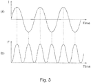
Fig. 3 shows in Part (a) a waveform of an electric current flowing through an excitation coil in the magnetic flux producing unit, andFig. 3 also shows in Part (b) a waveform of the Lorentz force produced in the magnetic flux producing unit. -
Fig. 4 is a block diagram showing a speed detecting device according to a variation. -
Fig. 5A shows an example of the magnetic flux producing unit having a yoke and an excitation coil wound thereon. -
Fig. 5B shows another example of the magnetic flux producing unit having a yoke and an excitation coil wound thereon. -
Fig. 5C shows another example of the magnetic flux producing unit having a yoke and an excitation coil wound thereon. -
Fig. 6 schematically shows a speed detecting device according to a second embodiment of the present invention. -
Fig. 7A schematically shows a speed detecting device according to a third embodiment of the present invention. -
Fig. 7B schematically shows a variation ofFig. 7A . - With reference to the appended drawings, the following describes one embodiment of the present disclosure. For convenience of illustration and ease of understanding, each of the drawings appended hereto appears in a scale size, an aspect ratio, and the like altered as appropriate from actual ones for emphasis.
- Moreover, terms, values, and so on used herein to specify a shape, a geometric condition, and an extent thereof, such as, for example, terms including "parallel," "orthogonal," and "equal" and values of a length and an angle, are not bound to a strict meaning thereof but should be interpreted as covering a range that can be expected to achieve similar functionality.
-
Fig. 1 schematically shows aspeed detecting device 1 according to a first embodiment of the present invention. Thespeed detecting device 1 inFig. 1 is provided with a magneticflux producing unit 2, astress detecting unit 3, astress transmitting member 4, a frequencyband extracting unit 5, and aspeed estimating unit 6. - The magnetic
flux producing unit 2 is spaced apart from aprincipal surface 7a of the relative movingbody 7 and configured to change at a predetermined frequency the magnetic flux passing over theprincipal surface 7a of the relative movingbody 7. The predetermined frequency is, for example, a frequency different from the frequency band related to the inertial force acting on thestress detecting unit 3 in accordance with the acceleration or deceleration of the relative movingbody 7. Alternatively, the predetermined frequency may be a frequency different from the frequency bands of disturbance noise detected by thestress detecting unit 3 in accordance with the acceleration or deceleration of the relative movingbody 7. The magneticflux producing unit 2 includes anexcitation coil 8 configured to change at a predetermined frequency the magnetic flux passing over theprincipal surface 7a of the relative movingbody 7. Theexcitation coil 8 is connected at both ends thereof to, for example, an alternating-current source 9, and the electric current flowing to theexcitation coil 8 alternates at a predetermined frequency. It is also possible to replace the alternating-current source 9 with, for example, a direct-current source and a switch and connect a capacitor to theexcitation coil 8 in series thereby to form a resonance circuit. Theexcitation coil 8 is wound along the surface of amagnetic member 10. When an alternating current flows through theexcitation coil 8 and the relative movingbody 7 is moved or rotated, themagnetic member 10 produces a Lorentz force in a direction according to the movement or rotation of the relative movingbody 7. - The
stress detecting unit 3 detects a stress and outputs an electric signal corresponding to the stress. Thestress detecting unit 3 is constituted by, for example, a force sensor, a strain sensor, a piezoelectric sensor, an air pressure sensor, or the like. - The
stress transmitting member 4 transmits to thestress detecting unit 3 the Lorentz force produced in the magneticflux producing unit 2 in accordance with the magnetic flux produced by the eddy currents occurring on the relative movingbody 7 in accordance with the moving or rotating speed of the relative movingbody 7. Thestress transmitting member 4 is, for example, a rigid member. The rigid member may be made of any material that preferably has such a rigidity capable of transmitting the Lorentz force produced in the magneticflux producing unit 2 to thestress detecting unit 3 without loss. More specifically, the rigid member is preferably made of a less deformable material such as a metal or a resin. Thestress transmitting member 4 may be an air pressure transmitting member such as a piston configured to compress the air with a compressive force in accordance with the stress. - The frequency
band extracting unit 5 extracts a frequency component related to the Lorentz force from the electric signal. The frequencyband extracting unit 5 includes, for example, a band-pass filter 11. The band-pass filter 11 has such a frequency characteristics as to pass mainly the frequency components related to the Lorentz force. - The
speed estimating unit 6 estimates the moving or rotating speed of the relative movingbody 7 based on the frequency component extracted by the frequencyband extracting unit 5. - The relative moving
body 7 is a conductor that can produce an eddy current on theprincipal surface 7a thereof. The relative movingbody 7 is spaced by a gap from one end portion of the magneticflux producing unit 2. Hereinafter, a description will be first given of the principle of the Lorentz force produced in the magneticflux producing unit 2 when the relative movingbody 7 moves in a predetermined direction in a state where the magneticflux producing unit 2 changes the magnetic flux at a predetermined frequency. -
Eddy currents principal surface 7a of the relative movingbody 7 in accordance with the moving speed of the relative movingbody 7. The direction of theeddy currents body 7. Since the magnetic flux produced in the magneticflux producing unit 2 changes periodically, the magnitude of theeddy currents body 7 moves, but the movement of the relative movingbody 7 may also refer to the case where the relative movingbody 7 is stationary and the magneticflux producing unit 2 moves. That is, the movement of the relative movingbody 7 refers to relative movement between the relative movingbody 7 and the magneticflux producing unit 2. The gap between theprincipal surface 7a of the relative movingbody 7 and the magneticflux producing unit 2 is limited within a range where the magnetic flux from the magneticflux producing unit 2 can reach theprincipal surface 7a of the relative movingbody 7. In addition, the term "movement" used herein may include "rotation." The relative movingbody 7 described herein may either move in a predetermined direction or rotate about a predetermined rotation axis. - As shown in
Fig. 2 , theeddy currents principal surface 7a of the relative movingbody 7 in accordance with the direction of the magnetic flux produced in the magneticflux producing unit 2, opposed to theprincipal surface 7a of the relative movingbody 7, and the moving direction of the relative movingbody 7. InFig. 1 , theeddy currents eddy currents body 7, eddy currents other than theeddy currents flux producing unit 2, but such eddy currents are not shown inFigs. 1 and2 . - When the relative moving
body 7 moves or rotates, theeddy currents principal surface 7a of the relative movingbody 7 in such a direction as to hinder a change of the magnetic flux from the magneticflux producing unit 2. The Lorentz force is produced in the magneticflux producing unit 2 by the interaction (the repulsive force and the attractive force) between the magnetic flux produced by theeddy currents flux producing unit 2. - For example, when a magnetic flux in a direction toward the
principal surface 7a of the relative movingbody 7 is produced in the magneticflux producing unit 2, the direction of the eddy current 12a occurring on theprincipal surface 7a of the relative movingbody 7 at a portion reached by the magnetic flux from an edge e1 of the magneticflux producing unit 2 at the front in the moving direction of the relative movingbody 7 is different from the direction of the eddy current 12b occurring on theprincipal surface 7a of the relative movingbody 7 at a portion reached by the magnetic flux from an edge e2 of the magneticflux producing unit 2 at the rear in the moving direction of the relative movingbody 7. The eddy current 12b generated by the magnetic flux from the edge e2 flows in such a direction as to generate magnetic flux in an opposite direction than the magnetic flux from the magneticflux producing unit 2. On the other hand, the eddy current 12a generated on theprincipal surface 7a of the relative movingbody 7 at a portion reached by the magnetic flux from the edge e1 flows in such a direction as to produce magnetic flux in the same direction as the magnetic flux from the magneticflux producing unit 2. Both theeddy currents flux producing unit 2 caused by rotation of the relative movingbody 7. - As described above, on the edge e1 side of the magnetic
flux producing unit 2 at the front in the moving direction of the relative movingbody 7, the direction of the magnetic flux caused by theeddy current 12a is the same as the direction of the magnetic flux from the magneticflux producing unit 2. Therefore, an attractive force acts between these magnetic fluxes. On the other hand, on the edge e2 side of the magneticflux producing unit 2 at the rear in the moving direction of the relative movingbody 7, the direction of the magnetic flux caused by the eddy current 12b is opposite to the direction of the magnetic flux from the magneticflux producing unit 2. Therefore, a repulsive force acts between these magnetic fluxes. The attractive force and the repulsive force impart a stress, or the Lorentz force, to the magneticflux producing unit 2 in a direction along the moving direction of the relative movingbody 7. - The Lorentz force produced in the magnetic
flux producing unit 2 may also be described as follows. The direction of theeddy current 12a produced by the magnetic flux from the edge e1 of the magneticflux producing unit 2 at the front in the moving direction of the relative movingbody 7 is opposite to the direction of the eddy current 12b produced by the magnetic flux from the edge e2 of the magneticflux producing unit 2 at the rear in the moving direction of the relative movingbody 7, and therefore, a current flows in a constant direction under the magneticflux producing unit 2 at all time. When the relative movingbody 7 rotates in the direction indicated by the arrow shown inFig. 2 , the currents generated by theeddy currents body 7. Therefore, the magneticflux producing unit 2 that receives the magnetic flux generated by theeddy currents body 7. This reaction force is the stress, or the Lorentz force, produced in the magneticflux producing unit 2. -
Fig. 3 shows in Part (a) a waveform of an electric current flowing through theexcitation coil 8 in the magneticflux producing unit 2, andFig. 3 also shows in Part (b) a waveform of the Lorentz force F produced in the magneticflux producing unit 2. As shown in Part (a) ofFig. 3 , the electric current flowing through theexcitation coil 8 has a sinusoidal waveform that changes at a predetermined frequency. On the other hand, the Lorentz force F produced in the magneticflux producing unit 2 has a frequency twice as high as the frequency of the electric current flowing through theexcitation coil 8, as shown in Part (b) ofFig. 3 . That is, when the electric current flowing through theexcitation coil 8 is the maximum or the minimum, the Lorentz force produced in the magneticflux producing unit 2 is the maximum. The Lorentz force F has a sinusoidal waveform with an amplitude varying in accordance with the moving or rotating speed of the relative movingbody 7. Part (b) ofFig. 3 shows an ideal sinusoidal waveform. When the moving or rotating speed of the relative movingbody 7 changes, the waveform of the Lorentz force combines the basic frequency component twice as high as the excitation current and the frequency component produced by acceleration or deceleration of the relative movingbody 7. As shown in Part (b) ofFig. 3 , the timing at which the electric current flowing through theexcitation coil 8 is the maximum or the minimum ideally corresponds to the timing at which the Lorentz force produced in the magneticflux producing unit 2 is the maximum, but actually, these timings may be different due to the hysteresis in the magnetic material of the core of theexcitation coil 8. - Accordingly, the moving or rotating speed of the relative moving
body 7 can be estimated by detecting the Lorentz force of Part (b) ofFig. 3 . Thus, in the embodiment, the Lorentz force produced in the magneticflux producing unit 2 is transmitted to thestress detecting unit 3 through thestress transmitting member 4, and thestress detecting unit 3 detects an electric signal in accordance with the Lorentz force. - However, the inertial force occurs upon acceleration or deceleration of the relative moving
body 7. When the inertial force occurs, the stress acting on the magneticflux producing unit 2 is changed. Therefore, upon acceleration or deceleration of the relative movingbody 7, the stress detected by thestress detecting unit 3 is changed by the amount of the inertial force, and the stress detected by thestress detecting unit 3 fails to indicate the Lorentz force produced in the magneticflux producing unit 2. - The inertial force acting on the magnetic
flux producing unit 2 can be expressed by a periodic function. The periodic function can be expressed as a sum of a plurality of sinusoidal waves having different frequencies by Fourier series expansion. Similarly, signals of the disturbance noise other than the inertial force (for example, vibration of the relative moving body 7) can all be subjected to frequency analysis. - In the embodiment, signal analysis of the disturbance noise including the inertial force is performed to set the frequency of the electric current flowing through the
excitation coil 8 in a frequency band not overlapping the frequency bands of the disturbance noise and set the passing frequency characteristics of the band-pass filter 11. - The inertial force changes in accordance with the acceleration of the relative moving
body 7. In addition, the disturbance noise other than the inertial force may be different occasionally. Therefore, it is desirable to previously detect the disturbance noise including the inertial force by simulation or experiments to grasp the frequency bands of the disturbance noise. - The band-
pass filter 11 has such a frequency characteristic as to cut off the frequency bands of the disturbance noise. Thus, the frequency components originated from the disturbance noise can be removed from the frequency components included in the electric signals that are output by thestress detecting unit 3 in accordance with the stress. - The electric signals that are output by the
stress detecting unit 3 in accordance with the stress have an amplitude changing in accordance with the stress, for example. Thus, assuming that the stress produced in the magneticflux producing unit 2 is the Lorentz force and is free of the disturbance noise, the amplitude of the electric signal output from thestress detecting unit 3 corresponds to the moving or rotating speed of the relative movingbody 7. Therefore, the correspondence between the amplitude of the electric signal from thestress detecting unit 3 and the moving or rotating speed of the relative movingbody 7 can be previously tabulated or expressed in a formula, such that thespeed estimating unit 6 can refer to the table or enter the electric signal of thestress detecting unit 3 to the formula to estimate the moving or rotating speed of the relative movingbody 7. -
Fig. 4 is a block diagram of thespeed detecting device 1 according to a variation, thespeed detecting device 1 additionally including a disturbancenoise detecting unit 13 and afrequency adjusting unit 14. The disturbancenoise detecting unit 13 detects disturbance noise in a vicinity of thespeed detecting device 1 by a piezoelectric element, an acceleration sensor, or the like. Various techniques are available for detecting disturbance noise, and any of such techniques may be employed. For example, the vibration of the relative movingbody 7 may be detected. The disturbancenoise detecting unit 13 may or may not detect the inertial force. The following description is based on an example in which the disturbancenoise detecting unit 13 does not detect the inertial force but previously detects the frequency band of the inertial force. - The
frequency adjusting unit 14 adjusts the excitation frequency of theexcitation coil 8 so as to differentiate the excitation frequency from the frequency band of the inertial force and the frequency bands of the disturbance noise detected by the disturbancenoise detecting unit 13, and thefrequency adjusting unit 14 also adjusts the frequency characteristics of the band-pass filter 11 so as to differentiate the passing frequency characteristics of the band-pass filter 11 from the frequency band of the inertial force and the frequency bands of the disturbance noise. - In the
speed detecting device 1 ofFigs. 1 and4 , it is assumed that the time average of the gap between theprincipal surface 7a of the relative movingbody 7 and the magneticflux producing unit 2 is constant. If the gap changes, the Lorentz force produced in the magneticflux producing unit 2 is changed, and the electric signal output from thestress detecting unit 3 is also changed. Therefore, when there is possibility that the time average of the gap is varied during movement or rotation of the relative movingbody 7, it is desirable to add a gap estimating unit for estimating the gap such that thespeed estimating unit 6 takes the estimated gap into account for estimating the moving or rotating speed of the relative movingbody 7. - The magnetic
flux producing unit 2 inFigs. 1 and4 includes themagnetic member 10 and theexcitation coil 8 wound on the surface of themagnetic member 10. It is also possible that the magneticflux producing unit 2 includes ayoke 20 of various shapes and theexcitation coil 8 wound thereon. InFig. 5A , the magneticflux producing unit 2 includes ayoke 20 of a U-shape and theexcitation coil 8 wound on the middle portion of theyoke 20. InFig. 5B , the magneticflux producing unit 2 includes ayoke 20 of an E-shape and theexcitation coil 8 wound on the middle branch portion of theyoke 20. InFig. 5C , the magneticflux producing unit 2 includes ayoke 20 of a U-shape and theexcitation coil 8 wound on both the branch portions of theyoke 20. The shape of theyoke 20 and the way of winding theexcitation coil 8 are not limited to those shown inFigs. 5A to 5C . Theyoke 20 makes it possible to produce a larger magnetic field with a smaller power consumption, resulting in a higher magnetic efficiency. - Thus, in the first embodiment, the Lorentz force produced in the magnetic
flux producing unit 2 by the magnetic flux caused by theeddy currents principal surface 7a of the relative movingbody 7 is transmitted to thestress detecting unit 3 through thestress transmitting member 4, and the disturbance noise including the inertial force is removed by the band-pass filter 11 from the electric signal output from thestress detecting unit 3 in accordance with the stress, before the speed of the relative movingbody 7 is estimated. Therefore, the speed of the relative movingbody 7 can be detected accurately without depending on the disturbance noise such as the inertial force. -
Fig. 6 schematically shows aspeed detecting device 1 according to a second embodiment of the present invention. Thespeed detecting device 1 ofFig. 6 is the same as inFig. 1 except that the magneticflux producing unit 2 is different from that inFig. 1 . - The magnetic
flux producing unit 2 inFig. 6 includes apermanent magnet 15, avoice coil 16 wound on the surface of thepermanent magnet 15, and aspring member 17 connected to one end side of thepermanent magnet 15. When an alternating current flows through the voice coil, thepermanent magnet 15 receives a force and thespring member 17 is compressed or expanded, which changes the gap between the magnetic pole on the other end side of thepermanent magnet 15 and theprincipal surface 7a of the relative movingbody 7. - As the gap is smaller, the magnetic field intensity on the
principal surface 7a of the relative movingbody 7 is higher, and as the gap is larger, the magnetic field intensity on theprincipal surface 7a of the relative movingbody 7 is lower. Therefore, the magnetic field intensity on theprincipal surface 7a of the relative movingbody 7 changes periodically. The change in the magnetic field intensity produces theeddy currents principal surface 7a of the relative movingbody 7 with a magnitude thereof changing periodically. Since the magnitude of theeddy currents flux producing unit 2 also changes periodically. The passing frequency characteristics of the band-pass filter 11 may be set in accordance with the frequency of the Lorentz force, so as to remove the noise components detected by thestress detecting unit 3. The frequency components of the Lorentz force having passed through the band-pass filter 11 are input to thespeed estimating unit 6 to estimate the moving or rotating speed of the relative movingbody 7. - When the relative moving
body 7 moves or rotates, theeddy currents principal surface 7a of the relative movingbody 7 under the edges of thepermanent magnet 15. As inFig. 2 , the direction of theeddy current 12a produced by the magnetic flux from the edge at the front in the moving direction of the relative movingbody 7 is opposite to the direction of the eddy current 12b produced by the magnetic flux from the edge at the rear in the moving direction of the relative movingbody 7. Thus, the Lorentz force is produced in thepermanent magnet 15 in a direction according to the moving or rotating direction of the relative movingbody 7. - In
Fig. 6 , thepermanent magnet 15 and thestress detecting unit 3 are connected to each other through thestress transmitting member 4. Therefore, the Lorentz force produced in thepermanent magnet 15 is transmitted to thestress detecting unit 3 through thestress transmitting member 4. Thestress detecting unit 3 outputs an electric signal corresponding to the stress. The electric signal is filtered by the band-pass filter 11. As described above, the passing frequency characteristics of the band-pass filter 11 are set in accordance with the frequency at which the magnitude of theeddy currents principal surface 7a of the relative movingbody 7 changes. - The
speed detecting device 1 ofFig. 6 is also configured such that the frequency bands of the disturbance noise are previously detected, and the alternating current source 9 supplies to thevoice coil 16 an electric current having a frequency different from the frequency bands of the disturbance noise, so as to avoid an effect of the disturbance noise including the inertial force. In addition, the passing frequency characteristics of the band-pass filter 11 are adjusted in accordance with the frequency bands of the disturbance noise, so as to remove the frequency components of the disturbance noise by the band-pass filter 11. - Thus, the
speed estimating unit 6 ofFig. 6 can estimate the moving or rotating speed of the relative movingbody 7 accurately without an effect of the disturbance noise such as the inertial force As inFig. 4 , thespeed detecting device 1 ofFig. 6 may include the disturbancenoise detecting unit 13 and thefrequency adjusting unit 14. - As described above, in the second embodiment, the magnetic
flux producing unit 2 includes thepermanent magnet 15 and thevoice coil 16, and therefore, the speed of the relative movingbody 7 can be detected accurately without depending on the disturbance noise such as the inertial force, as in the first embodiment. Since the second embodiment uses thepermanent magnet 15, the magnetic field intensity on theprincipal surface 7a of the relative movingbody 7 can be increased even with a large gap between thepermanent magnet 15 and the relative movingbody 7. Further, even when a small electric current is supplied to thevoice coil 16, the magnetic field intensity on theprincipal surface 7a of the relative movingbody 7 can be changed sufficiently to produce theeddy currents -
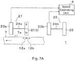
Figs. 7A and7B schematically show aspeed detecting device 1 according to a third embodiment of the present invention. Thespeed detecting device 1 ofFigs. 7A and7B includes afirst stress detector 21 and asecond stress detector 22 each outputting an electric signal corresponding to the stress, and thespeed estimating unit 6. The difference betweenFigs. 7A and7B is that thespeed detecting device 1 ofFig. 7A does not include a band-pass filter, whereas that ofFig. 7B includes the band-pass filter 11. - The
first stress detector 21 includes the magneticflux producing unit 2, a firststress detecting unit 23a, and a firststress transmitting member 24a. The magneticflux producing unit 2 is spaced apart from theprincipal surface 7a of the relative movingbody 7 and configured to produce magnetic flux passing theprincipal surface 7a of the relative moving body. The firststress detecting unit 23a detects a stress and outputs an electric signal corresponding to the stress. The firststress transmitting member 24a transmits to the firststress detecting unit 23a the Lorentz force produced in the magneticflux producing unit 2 in accordance with the magnetic flux produced by theeddy currents body 7 in accordance with the moving or rotating speed of the relative movingbody 7. - The
second stress detector 22 includes anon-magnetized member 25, a secondstress detecting unit 23b, and a secondstress transmitting member 24b. Thenon-magnetized member 25 is spaced apart from theprincipal surface 7a of the relative movingbody 7. The secondstress detecting unit 23b detects a stress and outputs an electric signal corresponding to the stress. The secondstress transmitting member 24b transmits to the secondstress detecting unit 23b the stress caused by the disturbance noise around the relative movingbody 7 including the inertial force corresponding to the movement or the rotation of the relative movingbody 7. - The magnetic
flux producing unit 2 may be, for example, apermanent magnet 15. Thepermanent magnet 15 is formed by applying an intensive magnetic field to a magnetizable substance for magnetization. Thenon-magnetized member 25 is made of the same magnetizable substance that forms a base for preparing thepermanent magnet 15 and is not magnetized. Thenon-magnetized member 25 is provided mainly to detect the inertial force, and thus may be referred to also as an inertial member. - The magnetic
flux producing unit 2 in thefirst stress detector 21 includes thepermanent magnet 15 and produces the Lorentz force in accordance with the moving or rotating speed of the relative movingbody 7. The stress produced in the magneticflux producing unit 2 includes the stress caused by the disturbance noise such as the inertial force, in addition to the Lorentz force. - On the other hand, the
non-magnetized member 25 in thesecond stress detector 22 is not magnetized, and therefore, theeddy currents principal surface 7a of the relative movingbody 7, and the Lorentz force is not produced in thenon-magnetized member 25 in accordance with the moving or rotating speed of the relative movingbody 7. Thenon-magnetized member 25 may be acted on by the stress caused by the disturbance noise such as the inertial force. - The
speed estimating unit 6 estimates the moving or rotating speed of the relative movingbody 7 based on a difference signal between the electric signal corresponding to the stress detected by thefirst stress detector 21 and the electric signal corresponding to the stress detected by thesecond stress detector 22. - The stress detected by the
first stress detector 21 includes both the Lorentz force produced in the magneticflux producing unit 2 in accordance with the moving or rotating speed of the relative movingbody 7 and the stress caused by the disturbance noise including the inertial force, whereas the stress detected by thesecond stress detector 22 does not include the Lorentz force and includes the stress caused by the disturbance noise including the inertial force. Therefore, taking the difference between the electric signals output from thefirst stress detector 21 and thesecond stress detector 22 makes it possible to cancel the stress caused by the disturbance noise including the inertial force and extract the Lorentz force only. Thus, thespeed detecting device 1 of the embodiment, which does not include the band-pass filter 11 as inFig. 7A , can detect the moving or rotating speed of the relative movingbody 7 accurately. Thespeed detecting device 1 ofFig. 7B includes the band-pass filter 11 for the purpose of canceling the disturbance noise other than the inertial force. - As described above, the third embodiment includes the
first stress detector 21 and thesecond stress detector 22, and the difference between the electric signals output from thefirst stress detector 21 and thesecond stress detector 22 is taken to cancel the disturbance noise. Therefore, the band-pass filter 11 is not necessary, resulting in a simple arrangement for detecting the moving or rotating speed of the relative movingbody 7 accurately. - The concept of the relative moving
body 7 in the first to third embodiments described above includes not only a relative moving body that itself moves or rotates but also a relative moving body that moves relative to thespeed detecting device 1. Therefore, in the first to third embodiments, in a case where thespeed detecting device 1 is installed in a train or the like, a fixture such as a rail that moves relative to the train or the like is also construed as being included in the concept of the relative movingbody 7. The relative movingbody 7 in the first to third embodiment is a conductor. - Aspects of the invention are not limited to the foregoing embodiments and embrace various modifications conceivable by those skilled in the art. Advantageous effects of the invention are also not limited to those described above. That is, various additions, changes, and partial deletions are possible in a range not departing from the conceptual ideas and spirit of the present invention derived from contents defined in the claims and equivalents thereof.
Claims (12)
- A speed detecting device (1), comprising:a magnetic flux producing unit (2) spaced apart from a principal surface of a relative moving body (7) and configured to change, at a predetermined frequency, magnetic flux passing over the principal surface of the relative moving body (7);a stress detecting unit (3) for detecting a stress and outputting an electric signal corresponding to the stress;a stress transmitting member (4) for transmitting to the stress detecting unit (3) a Lorentz force produced in the magnetic flux producing unit (2) in accordance with magnetic flux produced by eddy currents, the eddy currents occurring on the relative moving body (7) in accordance with a moving or rotating speed of the relative moving body (7);a frequency band extracting unit (5) for extracting a frequency component related to the Lorentz force from the electric signal; anda speed estimating unit (6) for estimating the moving or rotating speed of the relative moving body (7) based on the frequency component extracted by the frequency band extracting unit (5).
- The speed detecting device (1) according to claim 1, wherein the magnetic flux producing unit (2) sets the predetermined frequency at a frequency different from a frequency band related to an inertial force, the inertial force acting on the stress detecting unit (3) in accordance with acceleration or deceleration of the relative moving body (7).
- The speed detecting device (1) according to claim 1, wherein the magnetic flux producing unit (2) sets the predetermined frequency at a frequency different from a frequency band of disturbance noise detected by the stress detecting unit (3).
- The speed detecting device (1) according to any one of claims 1 to 3, wherein the magnetic flux producing unit (2) includes an excitation coil (8) configured to change at a predetermined frequency the magnetic flux passing over the principal surface of the relative moving body (7).
- The speed detecting device (1) according to any one of claims 1 to 3, wherein the magnetic flux producing unit (2) includes:a permanent magnet (15) spaced apart from and opposed to the principal surface of the relative moving body (7); anda voice coil (16) configured to change at the predetermined frequency a gap between the principal surface of the relative moving body (7) and the permanent magnet (15).
- The speed detecting device (1) according to any one of claims 1 to 5, further comprising:a disturbance noise detecting unit (13) for detecting disturbance noise around the relative moving body (7),wherein the magnetic flux producing unit (2) sets the predetermined frequency at a frequency different from a frequency band of the disturbance noise.
- The speed detecting device (1) according to any one of claims 1 to 6, wherein the stress transmitting member (4) is a rigid member that transmits the Lorentz force to the stress detecting unit (3).
- The speed detecting device (1) according to any one of claims 1 to 6, wherein the stress transmitting member (4) transmits an air pressure corresponding to the Lorentz force to the stress detecting unit (3).
- The speed detecting device (1) according to any one of claims 1 to 8, wherein the stress detecting unit (3) is a force sensor, a strain sensor, or an air pressure sensor.
- A speed detecting device (1), comprising:a first stress detector (21) and a second stress detector (22) each outputting an electric signal corresponding to a stress; anda speed estimating unit (6) for estimating a moving or rotating speed of a relative moving body (7) based on a difference signal between an electric signal output from the first stress detector (21) and the electric signal output from the second stress detector (22),wherein the first stress detector (21) includes:a magnetic flux producing unit (2) spaced apart from a principal surface of the relative moving body (7) and configured to change, at a predetermined frequency, magnetic flux passing over the principal surface of the relative moving body (7);a first stress detecting unit (3) for detecting the stress and outputting an electric signal corresponding to the stress; anda first stress transmitting member (4) for transmitting to the first stress detecting unit (3) a Lorentz force produced in the magnetic flux producing unit (2) in accordance with magnetic flux produced by eddy currents, the eddy currents occurring on the relative moving body (7) in accordance with a moving or rotating speed of the relative moving body (7), wherein the second stress detector (22) includes:a non-magnetized member (25) spaced apart from the principal surface of the relative moving body (7); anda second stress detecting unit (3) for detecting the stress and outputting an electric signal corresponding to the stress; anda second stress transmitting member (4) for transmitting to the second stress detecting unit (3) a stress caused by disturbance noise around the relative moving body (7) including an inertial force corresponding to movement or rotation of the relative moving body (7).
- The speed detecting device (1) according to any one of claims 1 to 10, wherein the relative moving body (7) is a wheel of a train or a rail, and wherein the magnetic flux producing unit (2) sets the predetermined frequency at a frequency different from a vibration frequency band of the train.
- A speed detecting method, comprising steps of:changing, at a predetermined frequency, magnetic flux passing over a principal surface of a relative moving body (7), by means of a magnetic flux producing unit (2) spaced apart from the principal surface of the relative moving body (7);detecting a stress and outputting an electric signal corresponding to the stress, by means of a stress detecting unit (3);transmitting to the stress detecting unit (3) a Lorentz force produced in the magnetic flux producing unit (2) in accordance with magnetic flux produced by eddy currents, the eddy currents occurring on the relative moving body (7) in accordance with a moving or rotating speed of the relative moving body (7);extracting a frequency component related to the Lorentz force from the electric signal; andestimating the moving or rotating speed of the relative moving body (7) based on the extracted frequency component.
Applications Claiming Priority (1)
| Application Number | Priority Date | Filing Date | Title |
|---|---|---|---|
| JP2018102399A JP7046720B2 (en) | 2018-05-29 | 2018-05-29 | Speed detection device and speed detection method |
Publications (3)
| Publication Number | Publication Date |
|---|---|
| EP3584586A2 true EP3584586A2 (en) | 2019-12-25 |
| EP3584586A3 EP3584586A3 (en) | 2020-04-08 |
| EP3584586B1 EP3584586B1 (en) | 2022-02-09 |
Family
ID=66668802
Family Applications (1)
| Application Number | Title | Priority Date | Filing Date |
|---|---|---|---|
| EP19176947.0A Active EP3584586B1 (en) | 2018-05-29 | 2019-05-28 | Speed detecting device and speed detecting method |
Country Status (3)
| Country | Link |
|---|---|
| EP (1) | EP3584586B1 (en) |
| JP (1) | JP7046720B2 (en) |
| CN (1) | CN110542765B (en) |
Families Citing this family (1)
| Publication number | Priority date | Publication date | Assignee | Title |
|---|---|---|---|---|
| CN113253282A (en) * | 2021-06-02 | 2021-08-13 | 爱德森(厦门)电子有限公司 | Moving speed detection method of nondestructive detection device and system device thereof |
Family Cites Families (15)
| Publication number | Priority date | Publication date | Assignee | Title |
|---|---|---|---|---|
| JP2653671B2 (en) | 1988-05-31 | 1997-09-17 | 財団法人鉄道総合技術研究所 | Vehicle speed detection device |
| JPH08211085A (en) * | 1994-07-01 | 1996-08-20 | Nkk Corp | Flow velocity measuring device |
| JPH1016761A (en) * | 1996-04-30 | 1998-01-20 | Nippon Soken Inc | Dragging torque measuring device of disk brake |
| GB9712750D0 (en) * | 1997-06-17 | 1997-08-20 | Penny & Giles International Pl | Improvements relating to velocity sensors |
| SE520648C2 (en) | 1999-03-25 | 2003-08-05 | Mpc Metal Process Control Ab | Method and apparatus for measuring a parameter of a metal web |
| DE102005046910B4 (en) * | 2005-09-21 | 2009-03-19 | Technische Universität Ilmenau | Method and arrangement for non-contact inspection of moving electrically conductive substances |
| DE102012017871A1 (en) * | 2012-09-06 | 2014-03-06 | Institut Dr. Foerster Gmbh & Co. Kg | Differential sensor and method for detecting anomalies in electrically conductive materials |
| WO2015059911A1 (en) * | 2013-10-21 | 2015-04-30 | パナソニックIpマネジメント株式会社 | Rotation speed detection device |
| CN103575803A (en) * | 2013-11-19 | 2014-02-12 | 南昌航空大学 | Lorentz force eddy current testing method and device for detecting defects of nonferromagnetic metal material |
| JP2015152473A (en) * | 2014-02-17 | 2015-08-24 | 株式会社デンソー | Detector |
| JP6206352B2 (en) * | 2014-07-17 | 2017-10-04 | Jfeスチール株式会社 | Molten steel flow velocity measuring method and molten steel flow velocity measuring apparatus |
| US11226211B2 (en) * | 2014-09-08 | 2022-01-18 | Texas Instruments Incorporated | Inductive position detection |
| JP6639810B2 (en) * | 2015-06-10 | 2020-02-05 | ナブテスコ株式会社 | Rotating electric machines and non-contact generators |
| CN105116049B (en) * | 2015-08-17 | 2018-02-06 | 中国科学院大学 | Vortex flow detection method |
| CN105510433B (en) * | 2016-02-05 | 2018-12-25 | 四川大学 | A kind of metal tube electromagnetic nondestructive device based on dynamic raw eddy current |
-
2018
- 2018-05-29 JP JP2018102399A patent/JP7046720B2/en active Active
-
2019
- 2019-05-28 EP EP19176947.0A patent/EP3584586B1/en active Active
- 2019-05-29 CN CN201910458617.0A patent/CN110542765B/en active Active
Also Published As
| Publication number | Publication date |
|---|---|
| EP3584586A3 (en) | 2020-04-08 |
| CN110542765B (en) | 2023-04-07 |
| CN110542765A (en) | 2019-12-06 |
| EP3584586B1 (en) | 2022-02-09 |
| JP7046720B2 (en) | 2022-04-04 |
| JP2019207149A (en) | 2019-12-05 |
Similar Documents
| Publication | Publication Date | Title |
|---|---|---|
| CN103782134B (en) | Enter line amplitude estimation in differential transformer displacement sensor using Goerzel algorithm | |
| US9983073B2 (en) | Solid borne sound wave phase delay comparison | |
| DE60034001D1 (en) | Vibratory type linear actuator and method of operating the same | |
| JP7001386B2 (en) | Speed detection device and speed detection method | |
| CN104295657B (en) | Damper and vibration damper complement | |
| EP3584586B1 (en) | Speed detecting device and speed detecting method | |
| EP2620670A1 (en) | Active damping device, vehicle, method for controlling active damping device | |
| CN110542764B (en) | Speed detection device and speed detection method | |
| Matsuda et al. | Self-sensing active suppression of vibration of flexible steel sheet | |
| JP2009293800A6 (en) | Method for supporting an object | |
| CN105605142A (en) | Method for automatically sensing displacement of magnetic suspension actuators in active-passive hybrid vibration isolating system | |
| SE0002796L (en) | Method for driving and position measurement of an actuator | |
| EP2433029B1 (en) | Device, method and program for automatic control computers for electromagnetic dampers | |
| JP6149593B2 (en) | Vibration generator | |
| JP3895479B2 (en) | Vibration test apparatus and vibration test apparatus control method | |
| CN208847440U (en) | A kind of adjustable non-contacting type electromagnetic excitation system of exciting point of force application | |
| CN108344494A (en) | Low frequency electromagnetic shake table movement velocity detection device based on induction coil | |
| JP2017139964A (en) | Oscillatory generator | |
| RU2038679C1 (en) | Electrodynamic transducer | |
| CN212391192U (en) | Magnetic circuit structure and magnetoelectric vibration table with same | |
| SU1629642A1 (en) | Liquid damper | |
| SU1500389A1 (en) | Electromagnetic vibration exciter | |
| KR101751485B1 (en) | Inductive Displacement Sensor Using Amplitude Modulation | |
| JP2019207150A (en) | Speed detector | |
| RU2009107451A (en) | METHOD FOR DETECTING THE INERT MASS OF THE MAGNION FIELD AND A DEVICE FOR ITS IMPLEMENTATION |
Legal Events
| Date | Code | Title | Description |
|---|---|---|---|
| PUAI | Public reference made under article 153(3) epc to a published international application that has entered the european phase |
Free format text: ORIGINAL CODE: 0009012 |
|
| STAA | Information on the status of an ep patent application or granted ep patent |
Free format text: STATUS: THE APPLICATION HAS BEEN PUBLISHED |
|
| AK | Designated contracting states |
Kind code of ref document: A2 Designated state(s): AL AT BE BG CH CY CZ DE DK EE ES FI FR GB GR HR HU IE IS IT LI LT LU LV MC MK MT NL NO PL PT RO RS SE SI SK SM TR |
|
| AX | Request for extension of the european patent |
Extension state: BA ME |
|
| PUAL | Search report despatched |
Free format text: ORIGINAL CODE: 0009013 |
|
| AK | Designated contracting states |
Kind code of ref document: A3 Designated state(s): AL AT BE BG CH CY CZ DE DK EE ES FI FR GB GR HR HU IE IS IT LI LT LU LV MC MK MT NL NO PL PT RO RS SE SI SK SM TR |
|
| AX | Request for extension of the european patent |
Extension state: BA ME |
|
| RIC1 | Information provided on ipc code assigned before grant |
Ipc: G01P 3/49 20060101AFI20200305BHEP Ipc: G01P 3/52 20060101ALI20200305BHEP Ipc: G01P 3/50 20060101ALI20200305BHEP |
|
| STAA | Information on the status of an ep patent application or granted ep patent |
Free format text: STATUS: REQUEST FOR EXAMINATION WAS MADE |
|
| 17P | Request for examination filed |
Effective date: 20201008 |
|
| RBV | Designated contracting states (corrected) |
Designated state(s): AL AT BE BG CH CY CZ DE DK EE ES FI FR GB GR HR HU IE IS IT LI LT LU LV MC MK MT NL NO PL PT RO RS SE SI SK SM TR |
|
| GRAP | Despatch of communication of intention to grant a patent |
Free format text: ORIGINAL CODE: EPIDOSNIGR1 |
|
| STAA | Information on the status of an ep patent application or granted ep patent |
Free format text: STATUS: GRANT OF PATENT IS INTENDED |
|
| INTG | Intention to grant announced |
Effective date: 20210906 |
|
| GRAS | Grant fee paid |
Free format text: ORIGINAL CODE: EPIDOSNIGR3 |
|
| GRAA | (expected) grant |
Free format text: ORIGINAL CODE: 0009210 |
|
| STAA | Information on the status of an ep patent application or granted ep patent |
Free format text: STATUS: THE PATENT HAS BEEN GRANTED |
|
| AK | Designated contracting states |
Kind code of ref document: B1 Designated state(s): AL AT BE BG CH CY CZ DE DK EE ES FI FR GB GR HR HU IE IS IT LI LT LU LV MC MK MT NL NO PL PT RO RS SE SI SK SM TR |
|
| REG | Reference to a national code |
Ref country code: GB Ref legal event code: FG4D |
|
| REG | Reference to a national code |
Ref country code: CH Ref legal event code: EP Ref country code: AT Ref legal event code: REF Ref document number: 1467829 Country of ref document: AT Kind code of ref document: T Effective date: 20220215 |
|
| REG | Reference to a national code |
Ref country code: IE Ref legal event code: FG4D |
|
| REG | Reference to a national code |
Ref country code: DE Ref legal event code: R096 Ref document number: 602019011410 Country of ref document: DE |
|
| REG | Reference to a national code |
Ref country code: LT Ref legal event code: MG9D |
|
| REG | Reference to a national code |
Ref country code: NL Ref legal event code: MP Effective date: 20220209 |
|
| REG | Reference to a national code |
Ref country code: AT Ref legal event code: MK05 Ref document number: 1467829 Country of ref document: AT Kind code of ref document: T Effective date: 20220209 |
|
| PG25 | Lapsed in a contracting state [announced via postgrant information from national office to epo] |
Ref country code: SE Free format text: LAPSE BECAUSE OF FAILURE TO SUBMIT A TRANSLATION OF THE DESCRIPTION OR TO PAY THE FEE WITHIN THE PRESCRIBED TIME-LIMIT Effective date: 20220209 Ref country code: RS Free format text: LAPSE BECAUSE OF FAILURE TO SUBMIT A TRANSLATION OF THE DESCRIPTION OR TO PAY THE FEE WITHIN THE PRESCRIBED TIME-LIMIT Effective date: 20220209 Ref country code: PT Free format text: LAPSE BECAUSE OF FAILURE TO SUBMIT A TRANSLATION OF THE DESCRIPTION OR TO PAY THE FEE WITHIN THE PRESCRIBED TIME-LIMIT Effective date: 20220609 Ref country code: NO Free format text: LAPSE BECAUSE OF FAILURE TO SUBMIT A TRANSLATION OF THE DESCRIPTION OR TO PAY THE FEE WITHIN THE PRESCRIBED TIME-LIMIT Effective date: 20220509 Ref country code: NL Free format text: LAPSE BECAUSE OF FAILURE TO SUBMIT A TRANSLATION OF THE DESCRIPTION OR TO PAY THE FEE WITHIN THE PRESCRIBED TIME-LIMIT Effective date: 20220209 Ref country code: LT Free format text: LAPSE BECAUSE OF FAILURE TO SUBMIT A TRANSLATION OF THE DESCRIPTION OR TO PAY THE FEE WITHIN THE PRESCRIBED TIME-LIMIT Effective date: 20220209 Ref country code: HR Free format text: LAPSE BECAUSE OF FAILURE TO SUBMIT A TRANSLATION OF THE DESCRIPTION OR TO PAY THE FEE WITHIN THE PRESCRIBED TIME-LIMIT Effective date: 20220209 Ref country code: ES Free format text: LAPSE BECAUSE OF FAILURE TO SUBMIT A TRANSLATION OF THE DESCRIPTION OR TO PAY THE FEE WITHIN THE PRESCRIBED TIME-LIMIT Effective date: 20220209 Ref country code: BG Free format text: LAPSE BECAUSE OF FAILURE TO SUBMIT A TRANSLATION OF THE DESCRIPTION OR TO PAY THE FEE WITHIN THE PRESCRIBED TIME-LIMIT Effective date: 20220509 |
|
| PG25 | Lapsed in a contracting state [announced via postgrant information from national office to epo] |
Ref country code: PL Free format text: LAPSE BECAUSE OF FAILURE TO SUBMIT A TRANSLATION OF THE DESCRIPTION OR TO PAY THE FEE WITHIN THE PRESCRIBED TIME-LIMIT Effective date: 20220209 Ref country code: LV Free format text: LAPSE BECAUSE OF FAILURE TO SUBMIT A TRANSLATION OF THE DESCRIPTION OR TO PAY THE FEE WITHIN THE PRESCRIBED TIME-LIMIT Effective date: 20220209 Ref country code: GR Free format text: LAPSE BECAUSE OF FAILURE TO SUBMIT A TRANSLATION OF THE DESCRIPTION OR TO PAY THE FEE WITHIN THE PRESCRIBED TIME-LIMIT Effective date: 20220510 Ref country code: FI Free format text: LAPSE BECAUSE OF FAILURE TO SUBMIT A TRANSLATION OF THE DESCRIPTION OR TO PAY THE FEE WITHIN THE PRESCRIBED TIME-LIMIT Effective date: 20220209 Ref country code: AT Free format text: LAPSE BECAUSE OF FAILURE TO SUBMIT A TRANSLATION OF THE DESCRIPTION OR TO PAY THE FEE WITHIN THE PRESCRIBED TIME-LIMIT Effective date: 20220209 |
|
| PG25 | Lapsed in a contracting state [announced via postgrant information from national office to epo] |
Ref country code: IS Free format text: LAPSE BECAUSE OF FAILURE TO SUBMIT A TRANSLATION OF THE DESCRIPTION OR TO PAY THE FEE WITHIN THE PRESCRIBED TIME-LIMIT Effective date: 20220609 |
|
| PG25 | Lapsed in a contracting state [announced via postgrant information from national office to epo] |
Ref country code: SM Free format text: LAPSE BECAUSE OF FAILURE TO SUBMIT A TRANSLATION OF THE DESCRIPTION OR TO PAY THE FEE WITHIN THE PRESCRIBED TIME-LIMIT Effective date: 20220209 Ref country code: SK Free format text: LAPSE BECAUSE OF FAILURE TO SUBMIT A TRANSLATION OF THE DESCRIPTION OR TO PAY THE FEE WITHIN THE PRESCRIBED TIME-LIMIT Effective date: 20220209 Ref country code: RO Free format text: LAPSE BECAUSE OF FAILURE TO SUBMIT A TRANSLATION OF THE DESCRIPTION OR TO PAY THE FEE WITHIN THE PRESCRIBED TIME-LIMIT Effective date: 20220209 Ref country code: EE Free format text: LAPSE BECAUSE OF FAILURE TO SUBMIT A TRANSLATION OF THE DESCRIPTION OR TO PAY THE FEE WITHIN THE PRESCRIBED TIME-LIMIT Effective date: 20220209 Ref country code: DK Free format text: LAPSE BECAUSE OF FAILURE TO SUBMIT A TRANSLATION OF THE DESCRIPTION OR TO PAY THE FEE WITHIN THE PRESCRIBED TIME-LIMIT Effective date: 20220209 Ref country code: CZ Free format text: LAPSE BECAUSE OF FAILURE TO SUBMIT A TRANSLATION OF THE DESCRIPTION OR TO PAY THE FEE WITHIN THE PRESCRIBED TIME-LIMIT Effective date: 20220209 |
|
| REG | Reference to a national code |
Ref country code: DE Ref legal event code: R097 Ref document number: 602019011410 Country of ref document: DE |
|
| PG25 | Lapsed in a contracting state [announced via postgrant information from national office to epo] |
Ref country code: AL Free format text: LAPSE BECAUSE OF FAILURE TO SUBMIT A TRANSLATION OF THE DESCRIPTION OR TO PAY THE FEE WITHIN THE PRESCRIBED TIME-LIMIT Effective date: 20220209 |
|
| PLBE | No opposition filed within time limit |
Free format text: ORIGINAL CODE: 0009261 |
|
| STAA | Information on the status of an ep patent application or granted ep patent |
Free format text: STATUS: NO OPPOSITION FILED WITHIN TIME LIMIT |
|
| REG | Reference to a national code |
Ref country code: CH Ref legal event code: PL |
|
| 26N | No opposition filed |
Effective date: 20221110 |
|
| REG | Reference to a national code |
Ref country code: BE Ref legal event code: MM Effective date: 20220531 |
|
| PG25 | Lapsed in a contracting state [announced via postgrant information from national office to epo] |
Ref country code: MC Free format text: LAPSE BECAUSE OF FAILURE TO SUBMIT A TRANSLATION OF THE DESCRIPTION OR TO PAY THE FEE WITHIN THE PRESCRIBED TIME-LIMIT Effective date: 20220209 Ref country code: LU Free format text: LAPSE BECAUSE OF NON-PAYMENT OF DUE FEES Effective date: 20220528 Ref country code: LI Free format text: LAPSE BECAUSE OF NON-PAYMENT OF DUE FEES Effective date: 20220531 Ref country code: CH Free format text: LAPSE BECAUSE OF NON-PAYMENT OF DUE FEES Effective date: 20220531 |
|
| PG25 | Lapsed in a contracting state [announced via postgrant information from national office to epo] |
Ref country code: SI Free format text: LAPSE BECAUSE OF FAILURE TO SUBMIT A TRANSLATION OF THE DESCRIPTION OR TO PAY THE FEE WITHIN THE PRESCRIBED TIME-LIMIT Effective date: 20220209 |
|
| PG25 | Lapsed in a contracting state [announced via postgrant information from national office to epo] |
Ref country code: IE Free format text: LAPSE BECAUSE OF NON-PAYMENT OF DUE FEES Effective date: 20220528 |
|
| PG25 | Lapsed in a contracting state [announced via postgrant information from national office to epo] |
Ref country code: BE Free format text: LAPSE BECAUSE OF NON-PAYMENT OF DUE FEES Effective date: 20220531 |
|
| P01 | Opt-out of the competence of the unified patent court (upc) registered |
Effective date: 20230523 |
|
| PG25 | Lapsed in a contracting state [announced via postgrant information from national office to epo] |
Ref country code: IT Free format text: LAPSE BECAUSE OF FAILURE TO SUBMIT A TRANSLATION OF THE DESCRIPTION OR TO PAY THE FEE WITHIN THE PRESCRIBED TIME-LIMIT Effective date: 20220209 |
|
| PG25 | Lapsed in a contracting state [announced via postgrant information from national office to epo] |
Ref country code: MK Free format text: LAPSE BECAUSE OF FAILURE TO SUBMIT A TRANSLATION OF THE DESCRIPTION OR TO PAY THE FEE WITHIN THE PRESCRIBED TIME-LIMIT Effective date: 20220209 Ref country code: CY Free format text: LAPSE BECAUSE OF FAILURE TO SUBMIT A TRANSLATION OF THE DESCRIPTION OR TO PAY THE FEE WITHIN THE PRESCRIBED TIME-LIMIT Effective date: 20220209 |
|
| PG25 | Lapsed in a contracting state [announced via postgrant information from national office to epo] |
Ref country code: HU Free format text: LAPSE BECAUSE OF FAILURE TO SUBMIT A TRANSLATION OF THE DESCRIPTION OR TO PAY THE FEE WITHIN THE PRESCRIBED TIME-LIMIT; INVALID AB INITIO Effective date: 20190528 |
|
| PG25 | Lapsed in a contracting state [announced via postgrant information from national office to epo] |
Ref country code: MT Free format text: LAPSE BECAUSE OF FAILURE TO SUBMIT A TRANSLATION OF THE DESCRIPTION OR TO PAY THE FEE WITHIN THE PRESCRIBED TIME-LIMIT Effective date: 20220209 |
|
| PGFP | Annual fee paid to national office [announced via postgrant information from national office to epo] |
Ref country code: DE Payment date: 20250521 Year of fee payment: 7 |
|
| PGFP | Annual fee paid to national office [announced via postgrant information from national office to epo] |
Ref country code: GB Payment date: 20250527 Year of fee payment: 7 |
|
| PGFP | Annual fee paid to national office [announced via postgrant information from national office to epo] |
Ref country code: FR Payment date: 20250528 Year of fee payment: 7 |
|
| PG25 | Lapsed in a contracting state [announced via postgrant information from national office to epo] |
Ref country code: TR Free format text: LAPSE BECAUSE OF FAILURE TO SUBMIT A TRANSLATION OF THE DESCRIPTION OR TO PAY THE FEE WITHIN THE PRESCRIBED TIME-LIMIT Effective date: 20220209 |