JP2015152473A - Detector - Google Patents
Detector Download PDFInfo
- Publication number
- JP2015152473A JP2015152473A JP2014027401A JP2014027401A JP2015152473A JP 2015152473 A JP2015152473 A JP 2015152473A JP 2014027401 A JP2014027401 A JP 2014027401A JP 2014027401 A JP2014027401 A JP 2014027401A JP 2015152473 A JP2015152473 A JP 2015152473A
- Authority
- JP
- Japan
- Prior art keywords
- coil
- magnet
- output
- detection
- detection unit
- Prior art date
- Legal status (The legal status is an assumption and is not a legal conclusion. Google has not performed a legal analysis and makes no representation as to the accuracy of the status listed.)
- Pending
Links
Images




Landscapes
- Transmission And Conversion Of Sensor Element Output (AREA)
Abstract
Description
本発明は、被検体の移動を検出する検出装置に関する。 The present invention relates to a detection apparatus that detects movement of a subject.
従来より、非磁性体から形成された被検体の移動を、その被検体に非接触で検出する検出装置が知られている。
特許文献1に記載の検出装置は、被検体としてのタービンエンジンのファンブレードの回転方向に並べて配置した第1の足部、磁石及び第2の足部を背板によって接続している。足部と背板は磁性体であり、2本の足部にはそれぞれ逆向きにコイルが巻き回されている。2個のコイルは、反ファンブレード側から取り出された配線同士が直列接続され、ファンブレード側から取り出された配線がそれぞれ検出回路に接続されている。
この検出装置は、ファンブレードが回転する際、ファンブレードに生じた渦電流の磁界により2個のコイルに生じる誘導起電力を検出回路が検出する。一方、検出装置に外乱磁界が印加された際、2個のコイルに生じた起電力は打ち消される。
2. Description of the Related Art Conventionally, a detection apparatus that detects the movement of a subject formed from a nonmagnetic material without contacting the subject is known.
In the detection apparatus described in
In this detection device, when the fan blade rotates, the detection circuit detects the induced electromotive force generated in the two coils by the magnetic field of the eddy current generated in the fan blade. On the other hand, when a disturbance magnetic field is applied to the detection device, the electromotive forces generated in the two coils are canceled out.
しかしながら、特許文献1に記載の検出装置は、ファンブレードの回転方向に第1の足部と磁石と第2の足部とを並べて配置しているので、その体格が大きくなり、搭載性が悪化する。
また、この検出装置は、複数枚のファンブレードの間隔が狭い場合、一枚のファンブレードの渦電流の磁界が第1の足部に影響を与えると同時に、その前又は後に位置するファンブレードの渦電流の磁界が第2の足部に影響を与えるおそれがある。これにより、検出装置の検出精度が悪化することが懸念される。
本発明は上記問題に鑑みてなされたものであり、体格を小型化すると共に、非磁性の導体から形成された被検体を高精度に検出することの可能な検出装置を提供することを目的とする。
However, since the detection device described in
In addition, when the interval between the plurality of fan blades is narrow, this detection device affects the first foot part at the same time that the eddy current magnetic field of one fan blade affects the first foot part, and at the same time, The eddy current magnetic field may affect the second foot. Thereby, there is a concern that the detection accuracy of the detection device deteriorates.
The present invention has been made in view of the above problems, and an object thereof is to provide a detection device capable of detecting a subject formed from a nonmagnetic conductor with high accuracy while reducing the size of the physique. To do.
本発明は、被検体の移動を検出する検出装置において、磁石の一方の磁極側に設けた第1検出部と磁石の他方の磁極側に設けた第2検出部により、外乱磁界による両検出部の出力を打ち消し、被検体の渦電流の磁界による第1検出部の出力を検出することを特徴とする。 The present invention provides a detection apparatus for detecting movement of an object, wherein both detection units using a disturbance magnetic field are provided by a first detection unit provided on one magnetic pole side of a magnet and a second detection unit provided on the other magnetic pole side of the magnet. The output of the first detector is detected by the magnetic field of the eddy current of the subject.
これにより、第1検出部の反磁石側を被検体が移動すると、被検体には、被検体を貫く磁石の磁界を打ち消す向きに磁界を生じる起電力が生じ、そこに渦電流が流れる。この渦電流によって生じた磁界により、第1検出部の第1コアに流れる磁束が変化する。ここで、磁界の強さは距離の2乗に反比例するので、磁石を挟んで第1検出部の反対側に設けられた第2検出部の第2コアに流れる磁束は殆ど変化しない。そのため、検出装置は、第1コイルに生じる誘導起電力を検出することにより、被検体の移動を検出可能である。 As a result, when the subject moves on the counter magnet side of the first detection unit, an electromotive force is generated in the subject in a direction that cancels the magnetic field of the magnet penetrating the subject, and an eddy current flows there. The magnetic field generated by this eddy current changes the magnetic flux flowing through the first core of the first detection unit. Here, since the strength of the magnetic field is inversely proportional to the square of the distance, the magnetic flux flowing through the second core of the second detection unit provided on the opposite side of the first detection unit across the magnet hardly changes. Therefore, the detection apparatus can detect the movement of the subject by detecting the induced electromotive force generated in the first coil.
一方、第1検出部と第2検出部に対し同時に外乱磁界が印加される場合、検出装置は、第1コイルと第2コイルに同時に発生する誘導起電力を打ち消す。これにより、検出装置は、外乱磁界の影響を受けることなく、被検体の移動を高精度に検出することができる。 On the other hand, when a disturbance magnetic field is simultaneously applied to the first detection unit and the second detection unit, the detection device cancels the induced electromotive force generated simultaneously in the first coil and the second coil. Thereby, the detection apparatus can detect the movement of the subject with high accuracy without being affected by the disturbance magnetic field.
また、検出装置は、磁石の一方の磁極側に第1検出部を配置し、他方の磁極側に第2検出部を配置することで、その体格を小型化することが可能である。これにより、検出装置の搭載性を高めることができる。 Further, the detection device can be downsized by arranging the first detection unit on one magnetic pole side of the magnet and the second detection unit on the other magnetic pole side. Thereby, the mounting property of a detection apparatus can be improved.
さらに、検出装置は、被検体の移動方向に対して第1検出部と磁石と第2検出部とを垂直に配置することで、被検体が移動方向に複数個並んでいる場合、1個の被検体の移動を検出する際に、その前後に位置する他の被検体による影響を低減することができる。 Furthermore, the detection apparatus arranges the first detection unit, the magnet, and the second detection unit perpendicularly to the moving direction of the subject, so that when a plurality of subjects are arranged in the moving direction, When detecting the movement of the subject, it is possible to reduce the influence of other subjects located before and after that.
以下、本発明による実施形態を図面に基づいて説明する。
(第1実施形態)
本発明の第1実施形態を図1から図4に示す。第1実施形態の検出装置1は、例えばエンジンの過給機を構成するタービンブレード(以下「ブレード」という)2の回転数を検出するものである。本実施形態のブレード2が特許請求の範囲に記載の「被検体」の一例に相当する。
このブレード2は、例えばアルミ又はチタンなどの非磁性の導体から薄板状に形成されたものである。ブレード2は、図1の矢印Aで示す方向に、検出装置1と非接触で回転する。
Hereinafter, embodiments of the present invention will be described with reference to the drawings.
(First embodiment)
A first embodiment of the present invention is shown in FIGS. The
The
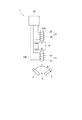
検出装置1は、磁石10、第1検出部11、第2検出部21及びケース30などを備えている。
磁石10は、ブレード側にN極、反ブレード側にS極が着磁されている。なお、磁石10は、N極とS極が逆向きに着磁されていてもよい。磁石10は、第1検出部11の第1コア12を通じて、ブレード2が通過する箇所に静磁界を形成する。
The
The
磁石10のN極側に第1検出部11が設けられ、S極側に第2検出部21が設けられる。
第1検出部11は、例えば鉄などの磁性体から形成された第1コア12と、その第1コア12の径外側に設けられた第1ボビン13と、その第1ボビン13に巻き回された第1コイル14を有する。
第2検出部21は、例えば鉄などの磁性体から形成された第2コア22と、その第2コア22の径外側に設けられた第2ボビン23と、その第2ボビン23に巻き回された第2コイル24を有する。
The
The
The
磁石10と第1コア12と第2コア22は、いずれも円柱状または角柱状に形成され、同軸に配置される。即ち、磁石10と第1コア12と第2コア22の中心軸Oは、同一である。
また、磁石10と第1検出部11の隙間の距離αと、磁石10と第2検出部21の隙間の距離βは同一である。
第1検出部11と第2検出部21とは同一の諸元である。即ち、第1コア12の径、長さ及び材質等と、第1コア12の径、長さ及び材質等は同一である。また、第1ボビン13の形状等と、第2ボビン23の形状等は同一である。また、第1コイル14の材質及び巻き数等と、第2コイル24の材質及び巻き数等は同一である。
The
Further, the distance α between the
The
図2に示すように、本実施形態では、第1コイル14の巻き方向と、第2コイル24の巻き方向とが反対向きである。軸方向から見て、第1コイル14は左巻きであり、第2コイル24は右巻きである。なお、軸方向から見て、第1コイル14を右巻きとして、第2コイル24を左巻きとしてもよい。
第1コイル14の磁石側から取り出された配線141は、第2コイル24の磁石側から取り出された配線241に直列接続されている。
As shown in FIG. 2, in the present embodiment, the winding direction of the
The
一方、第1コイル14の反磁石側から取り出された配線142と、第2コイル24の反磁石側から取り出された配線242は、図1に示す2本のワイヤケーブル31,32に電気的に接続される。2本のワイヤケーブル31,32は、コネクタ33に設けられた図示しない2本の端子に電気的に接続される。
本実施形態において、第1コイル14と第2コイル24の巻き方向を逆向きとして、第1コイル14の磁石側から取り出された配線141と第2コイル24の磁石側から取り出された配線241とを直列接続した構成が、特許請求の範囲に記載の「出力検出手段」の一例に相当する。
On the other hand, the
In this embodiment, the winding direction of the
ケース30は、非磁性体の金属又は樹脂などから形成され、上述した磁石10、第1検出部11、第2検出部21などを収容する。
The
次に、検出装置1がブレード2の回転数を検出する方法について説明する。
図3では、磁石10の磁界を鎖線B1で示し、ブレード2に流れる渦電流を一点鎖線Iで示し、その渦電流による磁界を2点鎖線B2で示している。ブレード2は、矢印Aで示す方向に回転する。
ブレード2が磁石10の磁界B1の範囲内を移動すると、ブレード2を貫く磁界B1の変化を打ち消す向きに磁界B2を生じるような起電力がブレード2に生じるため、そこに渦電流Iが流れる。この渦電流Iによって生じた磁界B2により、第1コア12を流れる磁束が変化する。これにより、第1コイル14に誘導起電力が生じる。
ここで、磁界の強さは距離の2乗に反比例するので、磁石10を挟んで第1コア12と反対側に設けられた第2コア22に流れる磁束は殆ど変化しない。そのため、第1コイル14と第2コイル24に直列接続されたコネクタ33の端子の電圧を検出することにより、検出装置1はブレード2の回転を検出することが可能である。
Next, a method in which the
In FIG. 3, the magnetic field of the
When the
Here, since the strength of the magnetic field is inversely proportional to the square of the distance, the magnetic flux flowing through the
続いて、検出装置1に対し、例えばロードヒーターや送電線などから外乱磁界が印加された場合について説明する。
第1検出部11と第2検出部21に対し同時に外乱磁界が印加されると、磁石10の磁界B1の変化に応じて第1コア12と第2コア22に流れる磁束が同時に変化し、第1コイル14と第2コイル24に起電力が生じる。第1コイル14と第2コイル24の巻き方向は逆向きであるので、第1コイル14に生じる起電力の方向と、第2コイル24に生じる起電力の方向とは逆向きである。そのため、第1コイル14の出力と第2コイル24の出力は打ち消される。これにより、検出装置1は、外乱磁界の影響を受けることなく、ブレード2の移動を高精度に検出することができる。
Then, the case where a disturbance magnetic field is applied with respect to the
When a disturbance magnetic field is applied to the
図4(A)は、検出装置1がブレード2の移動を検出する場合の第1コイル14の出力電圧と、第2コイル24の出力電圧と、検出装置1の出力電圧を示したものである。
図4(B)は、検出装置1に外乱磁界(ノイズ)を印加した場合の第1コイル14の出力電圧と、第2コイル24の出力電圧と、検出装置1の出力電圧を示したものである。
図4(A)に示すように、検出装置1がブレード2の移動を検出する場合、検出装置1をブレード2が横切るごとに、第1コイル14の出力電圧が大きく変化する。一方、第2コイル24の出力電圧は僅かに変化するものの、その出力電圧の変化は無視できる程度に小さい。したがって、第1コイル14と第2コイル24を直列接続した検出装置1の出力により、ブレード2の移動を正確に検出することが可能である。
FIG. 4A shows the output voltage of the
FIG. 4B shows the output voltage of the
As shown in FIG. 4A, when the
図4(B)に示すように、検出装置1に外乱磁界を印加した場合、第1コイル14の出力電圧と第2コイル24の出力電圧は同一の振高、波長で逆位相となる。そのため、第1コイル14と第2コイル24を直列接続した検出装置1の出力は0になる。したがって、検出装置1は、外乱磁界の影響を受けることなく、ブレード2の移動を正確に検出することが可能である。
As shown in FIG. 4B, when a disturbance magnetic field is applied to the
第1実施形態の検出装置1は、次の作用効果を奏する。
(1)第1実施形態では、検出装置1は、磁石10の一方の磁極側に第1検出部11を配置し、他方の磁極側に第2検出部21を配置している。これにより、検出装置1は、その体格を小型化することが可能である。したがって、検出装置1は、例えばエンジンの過給機等の搭載スペースが狭い場合でも容易に搭載することができる。
さらに、検出装置1は、第1検出部11、磁石10及び第2検出部21をブレード2の回転方向に対して垂直に配置することで、回転方向に複数枚のブレード2が並んでいる場合でも、検出目標のブレード2の前後に位置する他のブレード2の影響を受けず、ブレード2の回転数を正確に検出することができる。
The
(1) In 1st Embodiment, the
Furthermore, the
(2)第1実施形態では、検出装置1は、磁石10の磁極が並ぶ中心軸Oと、第1検出部11の中心軸Oと、第2検出部21の中心軸Oとが同一である。
これにより、検出装置1の体格を小型化し、その搭載性を高めることができる。
また、外乱磁界によって発生する第1コイル14の出力と第2コイル24の出力とが同等の大きさになるので、外乱磁界による影響を確実に打ち消すことができる。
(2) In the first embodiment, in the
Thereby, the physique of the
Further, since the output of the
(3)第1実施形態では、出力検出手段として、第1コイル14と第2コイル24の巻き方向を逆向きとし、第1コイル14の磁石側から取り出された配線141と第2コイル24の磁石側から取り出された配線241とを直列接続する。
これにより、外乱磁界が印加された場合に発生する第1コイル14の出力と第2コイル24の出力を打ち消すことが可能である。
また、第1コイル14と第2コイル24とを接続する配線141,241を短くすることが可能である。
(3) In the first embodiment, as the output detection means, the winding direction of the
Thereby, it is possible to cancel the output of the
In addition, the
(4)第1実施形態では、第1検出部11と第2検出部21とは同一の諸元である。
これにより、外乱磁界が印加された際に発生する第1コイル14の出力と第2コイル24の出力とが略同じ大きさになるので、外乱磁界の影響を確実に打ち消すことができる。
(4) In the first embodiment, the
Thereby, since the output of the
(5)第1実施形態では、磁石10と第1検出部11との隙間の距離αと、磁石10と第2検出部21との隙間の距離βとは同一である。
これにより、磁石10に対して第1検出部11と第2検出部21とが同じ距離で配置されるので、第1検出部11と第2検出部21に対する磁石10の磁界の強さが同じになる。そのため、外乱磁界が印加された際、磁石10の磁界の変化に応じた第1コア12の磁束の変化量と第2コア22の磁束の変化量とが同じになる。したがって、その際の第1コイル14の出力と第2コイル24の出力とが略同じ大きさになるので、検出装置1は、外乱磁界の影響を確実に打ち消すことができる。
(5) In the first embodiment, the gap distance α between the
Thereby, since the
(6)第1実施形態では、磁石10と第1検出部11との間に隙間が設けられ、磁石10と第2検出部21との間に隙間が設けられる。
これにより、第1コア12と第2コア22と磁石10を組付ける際、これらが衝突して磁石10が割れることを防ぐことができる。
(6) In the first embodiment, a gap is provided between the
Thereby, when assembling the
(第2実施形態)
本発明の第2実施形態の検出装置1を図5に示す。以下、複数の実施形態において上述した第1実施形態と実質的に同一の構成には同一の符号を付して説明を省略する。
第2実施形態では、磁石10と第1検出部11とが当接し、磁石10と第2検出部21とが当接している。
これにより、第2実施形態では、磁石10と第1検出部11とのエアギャップによる磁力の損失が小さくなるので、磁石10からブレード2に与える磁界が強くなる。そのため、ブレード2に生じる渦電流の磁界が強くなる。したがって、検出装置1は、感度が向上するので、ブレード2の回転を高精度に検出することができる。
(Second Embodiment)
A
In the second embodiment, the
Thereby, in 2nd Embodiment, since the loss of the magnetic force by the air gap of the
(第3実施形態)
本発明の第3実施形態の検出装置1を図6に示す。第3実施形態では、第1コイル14の両端の配線143,144と、第2コイル24の両端の配線243,244とが別々に電子回路40に接続されている。第1コイル14と第2コイル24の巻き方向は逆向きである。電子回路40は、第1コイル14の出力と第2コイル24の出力とを加算するものである。これにより、電子回路40は、外乱磁界の影響を打ち消し、ブレード2の移動を高精度に検出することができる。
第3実施形態の電子回路40は、特許請求の範囲に記載の「出力検出手段」の一例に相当する。
(Third embodiment)
A
The
(第4実施形態)
本発明の第4実施形態の検出装置1を図7及び図8に示す。図7に示すように、第4実施形態では、第1コイル14と第2コイル24の巻き方向が同じ向きである。第1コイル14の両端の配線143,144と、第2コイル24の両端の配線243,244とは、別々に電子回路40に接続されている。電子回路40は、第1コイル14の出力と第2コイル24の出力とを減算するものである。
(Fourth embodiment)
A
第4実施形態の検出装置1による電圧検出の解析図を図8に示す。
図8(A)は、検出装置1がブレード2の移動を検出する場合の第1コイル14の出力電圧と、第2コイル24の出力電圧と、電子回路40の出力電圧を示したものである。
図8(B)は、検出装置1に外乱磁界(ノイズ)を印加した場合の第1コイル14の出力電圧と、第2コイル24の出力電圧と、電子回路40の出力電圧を示したものである。
FIG. 8 shows an analysis diagram of voltage detection by the
FIG. 8A shows the output voltage of the
FIG. 8B shows the output voltage of the
図8(A)に示すように、検出装置1がブレード2の移動を検出する場合、第1コイル14の出力電圧が大きく変化する。一方、第2コイル24の出力電圧は無視できる程度に僅かに変化する。したがって、電子回路40は、第1コイル14の出力と第2コイル24の出力とを減算することにより、ブレード2の移動を正確に検出することが可能である。
As shown in FIG. 8A, when the
図8(B)に示すように、検出装置1に外乱磁界を印加した場合、第1コイル14の出力電圧と第2コイル24の出力電圧は同一の振高、波長で同位相となる。そのため、電子回路40は、第1コイル14の出力と第2コイル24の出力とを減算することにより、その出力は0になる。
したがって、検出装置1の電子回路40は、外乱磁界の影響を打ち消し、ブレード2の移動を正確に検出することができる。
As shown in FIG. 8B, when a disturbance magnetic field is applied to the
Therefore, the
(第5実施形態)
本発明の第5実施形態の検出装置1を図9に示す。第5実施形態では、第1コイル14と第2コイル24の巻き方向が同一である。第1コイル14の磁石側から取り出された配線145と第2コイル24の反磁石側から取り出された配線245とが直列接続されている。
これにより、外乱磁界が印加されると、第1コイル14に生じる起電力の方向と、第2コイル24に生じる起電力の方向とは同じ向きとなる。そのため、第1コイル14の磁石側の配線145と第2コイル24の反磁石側の配線245とが直列接続されていることから、第1コイル14の出力と第2コイル24の出力は打ち消される。これにより、検出装置1は、外乱磁界の影響を受けることなく、ブレード2の移動を高精度に検出することができる。
(Fifth embodiment)
A
Thereby, when a disturbance magnetic field is applied, the direction of the electromotive force generated in the
(他の実施形態)
(1)上述した実施形態では、ブレードの回転数を検出する検出装置について説明した。これに対し、他の実施形態では、検出装置は、非磁性の導体から形成された種々の被検体の移動を検出することが可能である。
(2)第1実施形態では、第1コイルと第2コイルの巻き方向を逆向きとして、第1コイルの磁石側から取り出された配線と、第2コイルの磁石側から取り出された配線とを直列接続した。
これに対し、他の実施形態では、第1コイルと第2コイルの巻き方向を逆向きとして、第1コイルの反磁石側から取り出された配線と、第2コイルの反磁石側から取り出された配線とを直列接続してもよい。この構成によっても、検出装置は、外乱磁界による影響を打ち消すことができる。
(3)また、第5実施形態では、第1コイルと第2コイルの巻き方向を同じ向きとして、第1コイルの反磁石側から取り出された配線と、第2コイルの磁石側から取り出された配線とを直列接続した。
これに対し、他の実施形態では、第1コイルと第2コイルの巻き方向を同じ向きとして、第1コイルの磁石側から取り出された配線と、第2コイルの反磁石側から取り出された配線とを直列接続してもよい。この構成によっても、検出装置は、外乱磁界による影響を打ち消すことができる。
本発明は、上記複数の実施形態に限定されるものではなく、発明の趣旨を逸脱しない範囲において、種々の形態で実施することができる。
(Other embodiments)
(1) In the above-described embodiment, the detection device that detects the rotation speed of the blade has been described. On the other hand, in other embodiments, the detection device can detect the movement of various subjects formed from nonmagnetic conductors.
(2) In the first embodiment, with the winding direction of the first coil and the second coil reversed, the wiring taken out from the magnet side of the first coil and the wiring taken out from the magnet side of the second coil Connected in series.
On the other hand, in other embodiments, the winding direction of the first coil and the second coil was reversed, and the wiring taken out from the antimagnet side of the first coil and the antimagnet side of the second coil were taken out. The wiring may be connected in series. Even with this configuration, the detection apparatus can cancel the influence of the disturbance magnetic field.
(3) Moreover, in 5th Embodiment, the winding direction of the 1st coil and the 2nd coil was made into the same direction, the wiring taken out from the antimagnet side of the 1st coil, and the magnet side of the 2nd coil were taken out. The wiring was connected in series.
On the other hand, in other embodiments, the winding direction of the first coil and the second coil is the same direction, the wiring taken out from the magnet side of the first coil, and the wiring taken out from the anti-magnet side of the second coil May be connected in series. Even with this configuration, the detection apparatus can cancel the influence of the disturbance magnetic field.
The present invention is not limited to the above-described embodiments, and can be implemented in various forms without departing from the spirit of the invention.
1 ・・・検出装置
2 ・・・ブレード(被検体)
10・・・磁石
11・・・第1検出部
12・・・第1コア
14・・・第1コイル
21・・・第2検出部
22・・・第2コア
24・・・第2コイル
DESCRIPTION OF
DESCRIPTION OF
Claims (9)
前記被検体が通過する箇所に磁界を生じる磁石(10)と、
磁性体の第1コア(12)、及びその第1コアの径外側に巻き回された第1コイル(14)を有し、前記磁石の一方の磁極側に設けられた第1検出部(11)と、
磁性体の第2コア(22)、及びその第2コアの径外側に巻き回された第2コイル(24)を有し、前記磁石の他方の磁極側に設けられた第2検出部(21)と、
外乱磁界による前記第1コイルの出力と前記第2コイルの出力を打ち消し、前記第1検出部の反磁石側を移動する前記被検体の渦電流の磁界による前記第1コイルの出力を検出する出力検出手段(14,141−145,24,241−245,40)と、を備えることを特徴とする検出装置。 A detection device (1) for detecting movement of a subject (2) formed from a non-magnetic conductor,
A magnet (10) that generates a magnetic field at a location where the subject passes;
A first detection unit (11) having a first core (12) of magnetic material and a first coil (14) wound around the outer diameter of the first core and provided on one magnetic pole side of the magnet. )When,
A second detector (21) having a second core (22) of magnetic material and a second coil (24) wound around the outer diameter of the second core and provided on the other magnetic pole side of the magnet. )When,
Output for detecting the output of the first coil due to the magnetic field of the eddy current of the subject moving on the side opposite to the magnet of the first detection unit by canceling the output of the first coil and the output of the second coil due to the disturbance magnetic field And a detecting means (14, 141-145, 24, 241-245, 40).
前記第1コイルと前記第2コイルの巻き方向が逆向きの場合、前記第1コイルの出力と前記第2コイルの出力とを加算する電子回路(40)であり、
前記第1コイルと前記第2コイルの巻き方向が同一の場合、前記第1コイルの出力と前記第2コイルの出力とを減算する電子回路であることを特徴とする請求項1または2に記載の検出装置。 The output detection means includes
An electronic circuit (40) for adding the output of the first coil and the output of the second coil when the winding direction of the first coil and the second coil is opposite;
3. The electronic circuit according to claim 1, wherein when the winding directions of the first coil and the second coil are the same, the electronic circuit subtracts the output of the first coil and the output of the second coil. Detection device.
前記第1コイルの材質及び巻き数と、前記第2コイルの材質及び巻き数とは同一であることを特徴とする請求項1から5のいずれか一項に記載の検出装置。 The diameter, length and material of the first core are the same as the diameter, length and material of the second core,
6. The detection device according to claim 1, wherein the material and the number of turns of the first coil are the same as the material and the number of turns of the second coil.
前記磁石と前記第2検出部との間に隙間が設けられることを特徴とする請求項1から7のいずれか一項に記載の検出装置。 A gap is provided between the magnet and the first detection unit,
The detection device according to claim 1, wherein a gap is provided between the magnet and the second detection unit.
Priority Applications (1)
| Application Number | Priority Date | Filing Date | Title |
|---|---|---|---|
| JP2014027401A JP2015152473A (en) | 2014-02-17 | 2014-02-17 | Detector |
Applications Claiming Priority (1)
| Application Number | Priority Date | Filing Date | Title |
|---|---|---|---|
| JP2014027401A JP2015152473A (en) | 2014-02-17 | 2014-02-17 | Detector |
Publications (1)
| Publication Number | Publication Date |
|---|---|
| JP2015152473A true JP2015152473A (en) | 2015-08-24 |
Family
ID=53894883
Family Applications (1)
| Application Number | Title | Priority Date | Filing Date |
|---|---|---|---|
| JP2014027401A Pending JP2015152473A (en) | 2014-02-17 | 2014-02-17 | Detector |
Country Status (1)
| Country | Link |
|---|---|
| JP (1) | JP2015152473A (en) |
Cited By (3)
| Publication number | Priority date | Publication date | Assignee | Title |
|---|---|---|---|---|
| JP2018179976A (en) * | 2017-04-17 | 2018-11-15 | 株式会社神戸製鋼所 | Moving speed detection device |
| US10139457B2 (en) | 2014-09-02 | 2018-11-27 | Denso Corporation | Detection device and manufacturing method thereof |
| CN110542765A (en) * | 2018-05-29 | 2019-12-06 | 纳博特斯克有限公司 | Speed detection device and speed detection method |
-
2014
- 2014-02-17 JP JP2014027401A patent/JP2015152473A/en active Pending
Cited By (5)
| Publication number | Priority date | Publication date | Assignee | Title |
|---|---|---|---|---|
| US10139457B2 (en) | 2014-09-02 | 2018-11-27 | Denso Corporation | Detection device and manufacturing method thereof |
| JP2018179976A (en) * | 2017-04-17 | 2018-11-15 | 株式会社神戸製鋼所 | Moving speed detection device |
| JP7025260B2 (en) | 2017-04-17 | 2022-02-24 | 株式会社神戸製鋼所 | Movement speed detector |
| CN110542765A (en) * | 2018-05-29 | 2019-12-06 | 纳博特斯克有限公司 | Speed detection device and speed detection method |
| EP3584586A3 (en) * | 2018-05-29 | 2020-04-08 | Nabtesco Corporation | Speed detecting device and speed detecting method |
Similar Documents
| Publication | Publication Date | Title |
|---|---|---|
| CN103733060B (en) | Magnetic method of detection and magnetic fault detector | |
| CN105471211B (en) | A kind of generator that can measure angular velocity of rotation, angular acceleration simultaneously | |
| JP7736468B2 (en) | Encoder systems for drives | |
| US8664962B2 (en) | Winding method and winding structure of stator for rotation detector, and electric motor comprising rotation detector | |
| CN105634235B (en) | Axle sleeve generator that is a kind of while measuring angular velocity of rotation, angular acceleration | |
| JP5927891B2 (en) | Rotation angle detector | |
| CN101793492B (en) | Low-noise magnetostrictive displacement sensor | |
| CN104034917A (en) | Shaft sleeve type permanent magnet rotation angle acceleration sensor | |
| US20130009523A1 (en) | Electromechanical device, robot, and mobile unit | |
| TWI921548B (en) | motion detector | |
| EP2941816A2 (en) | Position sensing system | |
| CN104483510B (en) | A kind of measuring method for measuring rotary acceleration sensors | |
| CN105467150B (en) | Portable electric generator that is a kind of while measuring angular velocity of rotation, angular acceleration | |
| JP2012501445A (en) | System and method for detecting the periodic position of an object | |
| JP6840970B2 (en) | Turbocharger with rotation speed detector | |
| JP7584336B2 (en) | Linear Variable Differential Transformer | |
| JP2011099837A (en) | Rotation angle sensor | |
| Niguchi et al. | Power generation performance analysis of a hub dynamo considering a magnetic hysteresis | |
| JP2015102366A (en) | Detection device | |
| Abdellatif et al. | Dynamic analysis of the simultaneous mixed eccentricity and broken rotor bars in induction machine based on magnetic field diagnosis | |
| JP2015211549A (en) | Motor generator | |
| WO2013018458A1 (en) | Surface current probe | |
| JP2015068757A (en) | Rotation sensor, motor equipped with the rotation sensor, and rotation detection method | |
| Lecointe et al. | Effects of external yoke and clamping-plates on AC motor external field | |
| CN204065130U (en) | D-axis and quadrature-axis reluctance permanent magnetism rotating angular acceleration sensor not etc. |