EP3584530A1 - Reifenlaufflächendetektionsvorrichtung und reifendruckdetektoreinstellvorrichtung mit reifenlaufflächendetektionsfunktion - Google Patents
Reifenlaufflächendetektionsvorrichtung und reifendruckdetektoreinstellvorrichtung mit reifenlaufflächendetektionsfunktion Download PDFInfo
- Publication number
- EP3584530A1 EP3584530A1 EP18189130.0A EP18189130A EP3584530A1 EP 3584530 A1 EP3584530 A1 EP 3584530A1 EP 18189130 A EP18189130 A EP 18189130A EP 3584530 A1 EP3584530 A1 EP 3584530A1
- Authority
- EP
- European Patent Office
- Prior art keywords
- tire
- sense
- driving unit
- tread
- pressure detector
- Prior art date
- Legal status (The legal status is an assumption and is not a legal conclusion. Google has not performed a legal analysis and makes no representation as to the accuracy of the status listed.)
- Pending
Links
Images


Classifications
-
- G—PHYSICS
- G01—MEASURING; TESTING
- G01B—MEASURING LENGTH, THICKNESS OR SIMILAR LINEAR DIMENSIONS; MEASURING ANGLES; MEASURING AREAS; MEASURING IRREGULARITIES OF SURFACES OR CONTOURS
- G01B7/00—Measuring arrangements characterised by the use of electric or magnetic techniques
- G01B7/26—Measuring arrangements characterised by the use of electric or magnetic techniques for measuring depth
-
- B—PERFORMING OPERATIONS; TRANSPORTING
- B60—VEHICLES IN GENERAL
- B60C—VEHICLE TYRES; TYRE INFLATION; TYRE CHANGING; CONNECTING VALVES TO INFLATABLE ELASTIC BODIES IN GENERAL; DEVICES OR ARRANGEMENTS RELATED TO TYRES
- B60C11/00—Tyre tread bands; Tread patterns; Anti-skid inserts
- B60C11/24—Wear-indicating arrangements
- B60C11/243—Tread wear sensors, e.g. electronic sensors
-
- G—PHYSICS
- G01—MEASURING; TESTING
- G01L—MEASURING FORCE, STRESS, TORQUE, WORK, MECHANICAL POWER, MECHANICAL EFFICIENCY, OR FLUID PRESSURE
- G01L17/00—Devices or apparatus for measuring tyre pressure or the pressure in other inflated bodies
- G01L17/005—Devices or apparatus for measuring tyre pressure or the pressure in other inflated bodies using a sensor contacting the exterior surface, e.g. for measuring deformation
Definitions
- the present invention relates to tire detection fields, and more particularly, to a tire pressure detector setting apparatus with tire tread detection function.
- Vehicle is a commonly used transportation for movement.
- tread depth of the tire is a key element for the vehicle driving safety.
- the tire tread depth determines the shock absorbing and water discharging performance of a tire.
- the frictional force of the tire When the tire tread depth becomes shallower due to the abrasion after usage, the frictional force of the tire also becomes lower, preventing the tire from efficiently gripping the road and possibly causing the vehicle to slip during a high-speed driving or emergency brake. Further, a flat tire may occurs, so as to affect the vehicle driving safety. Therefore, for securing the vehicle driving safety, the tire tread depth shall be examined before the vehicle getting on the road.
- the tire tread depth is able to be examined by use of a detection tool.
- the US patent US20140139332A1 discloses a vehicle tire inspection tool. With the head portion of the tread depth device provided with a pin, and by use of the pin end being inserted in the tire tread, the resistance variation is detected based on the variation of the strain gauge, such that the tire tread depth of the tire is acquired.
- the bonding quality will affect the inspection accuracy. Based on the reason that the resistance value of a metal wire is applied for inspecting the variation, the strain gauge has to be stably and accurately bonded to the inspection point for achieving the most accurate inspection result. If the bonding of the strain gauge is not properly carried out, the inspection accuracy will be affected, failing to acquire an accurate tire tread depth by use of the strain gauge.
- the pin permanently protrudes from the head portion.
- the portion of the pin will retract into the head portion, except for the portion inserted in the tire tread. Therefore, the strain gauge generates a variation amount according to the retraction of the pin into the head portion, so as to acquire a tire tread depth.
- the pin due to the pin permanently protruding from the head portion, the pin is easily bent or broken under an external force imposed thereon, causing the damage of the inspection tool.
- the present invention discloses a tire tread detection apparatus and a tire pressure detector with tire tread detection function for efficiently and accurately acquiring the tire tread depth, so as to improve the inaccuracy issue of detection and prevent possible damage.
- the driving unit drives the measuring member to protrude out from the body casing for measuring the tire tread depth. Therefore, the detection tool does not permanently protrude, thus preventing the detection tool from possible damage.
- the measuring member protrudes out from the body casing for measuring the tire tread depth
- a measurement signal is generated by the sense member and the positioning member that are corresponding with each other, such that the measurement signal is interpreted as the tread depth value of the tire tread. Therefore, by acquiring the tread depth value in a sensing manner, the tire tread depth is efficiently and accurately detected, thus improving the detection inaccuracy caused by the variation of the traditional strain gauge.
- a tire pressure detector setting apparatus with tire tread detection function which is coupled with a tire pressure detector, comprises:
- the tire pressure detector with tire tread detection function is allowed to set up the communication protocol of the tire pressure detector through the setting module. Therefore, the user is able to detect the tire tread depth by use of the tire tread detection module when installing the tire pressure detector or carrying out the tire pressure detection process.
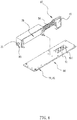
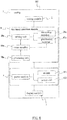
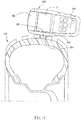
- a tire tread detection apparatus 100 for detecting the tire tread depth of a tire 200 in accordance with an embodiment of the present invention comprises a body casing 10, a driving unit 20, a measuring member 30, a positioning member 40, a sense member 60, a processing unit 70, a power module 80, and a display module 90 .
- the driving unit 20, the sense member 60, the processing unit 70, and the display module 90 are coupled with the power module 80, such that the power module 80 supplies power to the driving unit 20, the sense member 60, the processing unit 70, and the display module 90.
- the driving unit 20 is connected with the measuring member 30 and the positioning member 40.
- the driving unit 20 is applied for driving the measuring member 30 to move for measuring the tread depth of the tire 200.
- a sensing connection is established between the positioning member 40 and the sense member 60, so as to generate a measuring signal.
- the processing unit 70 receives the measuring signal and produces a tread depth value, which is displayed on the display module 90.
- the body casing 10 has a housing space 11 therein, and further has an opening 12 disposed at one lateral of the body casing 10.
- the opening 12 is connected with the housing space 11.
- the driving unit 20 is disposed in the housing space 11 of the body casing 10.
- the driving unit 20 is a solenoid valve.
- the power module 80 supplies power to the driving unit 20, the power energizes the electromagnetic coil of the driving unit 20 , such that the measuring member 30 and the positioning member 40 are driven to linearly move with respect to the body casing 10.
- the measuring member 30 is disposed in the housing space 11 of the body casing 10.
- the measuring member 30 is formed in a rod shape and comprises a detection end 31 disposed in adjacent to the opening 12.
- the detection end 31 is applied for being inserted in the tread groove 201 of the tire 200.
- the detection end 31 has an outer diameter preferably not larger than 6mm, so as to be applied for various models of tire 200.
- the driving unit 20 is allowed to drive the measuring member 30 to move between a retract position and a protrude position. When the measuring member 30 is at the retract position, the detection end 31 of the measuring member 30 is placed between the opening 12 and the housing space 11.
- the detection end 31 of the measuring member 30 protrudes out from the body casing 10 via the opening 12, so as to protrude into the tread groove 201 of the tire 200 for measuring the tread depth of the tire 200.
- the distance between the retract position and the protrude position is defined as the tread depth of the tire 200.
- the positioning member 40 is disposed in the housing space 11 of the body casing 10.
- the positioning member 40 has a sensing portion 41 for establishing a sense connection with the sense member 60. Therein, the sensing portion 41 is allowed to be formed in a metal material.
- the positioning member 40 has a spring 50 disposed at an outer periphery of thereof, with two ends of the spring 50 resting against the driving unit 20 and the sensing portion 41. Therein, when the driving unit 20 drives the measuring member 30 to move from the retract position to the protrude position, the spring 50 is compressed.
- the sense member 60 is fixed in the housing space 11 of the body casing 10. In an embodiment of the present invention, the sense member 60 is disposed at one end of the measuring member 30 away from the detection end 31.
- the sense member 60 is approximately formed in a plate shape, with a sense area 61 disposed at one lateral of the sense member 60 facing the positioning member 40.
- the sense area 61 corresponds to a movement range of the positioning member 40.
- the sense area 61 has a detection pattern 611, such that the power supplied by the power module 80 is conducted to the detection pattern 611.
- the detection pattern 611 is formed of a magnetic or metal material. When the sensing portion 41 of the positioning member 40 covers a portion of the detection pattern 611, the measurement signal generated by the sense member 60 varies according to the covered portion of the detection pattern 611.
- the portion of the detection pattern 611 of the sense area 61 covered by the sensing portion 41 formed of metal material produces a magnetic field. Therefore, the measurement signal generated by the sense member 60 is defined as the area range of the magnetic field. Also, the minimum detection unit is improved to reach a precision of 0.1mm.
- the processing unit 70 is disposed in the housing space 11 of the body casing 10 and coupled with the sense member 60.
- the sense member 60 transmits the measurement signal to the processing unit 70.
- the processing unit 70 performs a calculation with the measurement signal to acquire the tread depth value.
- the tread depth value is a character string formed of a numerical value.
- the power module 80 is disposed at the body casing 10 and comprises a switch 81 and a power unit 82.
- the switch 81 is applied for controlling the power unit 82 to provide the power to the driving unit 20, the sense member 60, the processing unit 70, and the display module 90.
- the switch 81 is disposed at an outer lateral of the body casing 10 away from the opening 12.
- the switch 81 is allowed to be chosen from a normal open or normal close switch, which is not limited in the embodiment of the present invention.
- the power unit 82 is disposed in the housing space 11 of the body casing 10.
- the power unit 82 is allowed to be chosen from a rechargeable form or battery form, which is not limited in the embodiment of the present invention.
- the display module 90 is disposed at the outer lateral of the body casing 10. In an embodiment of the present invention, the display module 90 is disposed at the outer lateral of the body casing 10 away from the opening 12, wherein the display module 90 and the switch 81 are disposed at the same lateral of the body casing 10.
- the user when measuring the tread depth of the tire 200, the user rests one lateral of the body casing 10 of the tire tread detection apparatus 100 provided with the opening 12 against the tread face of the tire 200, and aligns the opening 12 with the tread groove 201 of the tire 200.
- the user presses the switch 81, so that the power unit 82 supplies the power to the driving unit 20 and the driving unit 20 drives the measuring member 30 to move from the retract position to the protrude position, whereby the detection end 31 of the measuring member 30 rests against the bottom of the tread groove 201.
- the positioning member 40 moves together with the measuring member 30 until the detection end 31 reaches the bottom of the tread groove 201, so that the sensing portion 41 covers a portion of the detection pattern 611, such that the sense member 60 generates the measurement signal according to the covered portion of the detection pattern 611, and the processing unit 70 transforms the measurement signal to a tread depth value. Then, the processing unit 70 transmits the tread depth value to the display module 90, such that the display module 90 displays the tread depth value to inform the user about the current tread depth of the tire 200.
- the power module 80 stops supplying the power to the electromagnetic coil of the driving unit 20.
- the measuring member 30 With the resilient force of the spring 50, the measuring member 30 will move from the protrude position back to the retract position, such that the detection end 31 of the measuring member 30 completely retracts into the opening 12, completing the tread depth detection of the tire 200.
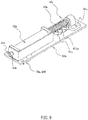
- a tire pressure detector setting apparatus 300 with tire tread detection function is provided for being coupled with the tire pressure detector.
- the tire pressure detector setting apparatus 300 comprises a casing 1, a setting module 2, a tire tread detection module 3, a power module 4, and a display module 5.
- the setting module 2, the tire tread detection module 3, and the power module 4 are disposed inside the casing 1, and the display module 5 is disposed at an outer lateral of the casing 1.
- the power module 4 supplies the power to the setting module 2, the tire tread detection module 3, and the display module 5.
- the casing 1 has a housing recess 101 disposed at a lateral thereof, with the housing recess 101 connected with the inside of the casing 1.
- the housing recess 101 houses the tire tread detection module 3, wherein the casing 1 has a cover 102 corresponding to the housing recess 101 for sealing tire tread detection module 3 in the housing recess 101.
- the cover 102 is provided with an opening 103.
- a connection seat 104 is disposed at an outer lateral of the casing 1, such that the tire pressure detector (not shown) is placed at the connection seat 104.
- the setting module 2 is disposed in the casing 1 and comprises a plurality of communication protocol information.
- the setting module 2 is electrically connected with the tire pressure detector through the connection seat 104, such that one of the communication protocol information is able to be written into the tire pressure detector.
- the casing 1 does not has the connection seat 104, and the setting module 2 writes one of the communication protocol information into the tire pressure detector through a wireless connection.
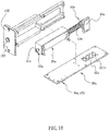
- the tire tread detection module 3 comprises a driving unit 20a, a measuring member 30a, a positioning member 40a, a sense member 60a, and a processing unit 70a.
- the driving unit 20a is connected with the measuring member 30a and the positioning member 40a.
- the driving unit 20a drives the measuring member 30 to move for measuring the tread depth of the tire 200.
- the positioning member 40a senses the sense member 60 during the movement of the measuring member 30a, such that a measurement signal is generated.
- the processing unit 70a receives the measurement signal and produces a corresponding tread depth value.
- the driving unit 20a is a solenoid valve.
- the power module 80a supplies the power to the driving unit 20a, the power is conducted to the electromagnetic coil of the driving unit 20a, so as to drive the measuring member 30a and the positioning member 40a to linearly move with respect to the casing 1.
- the measuring member 30a is formed in a rod shape and comprises a detection end 31a disposed in adjacent to the opening 103. Therein, the detection end 31a is applied for being inserted in the tread groove 201 of the tire 200.
- the detection end 31a has an outer diameter preferably not larger than 6mm, so as to be applied for various models of tire 200.
- the driving unit 20a is allowed to drive the measuring member 30a to move between a retract position and a protrude position. When the measuring member 30a is at the retract position, the detection end 31a of the measuring member 30a is placed between the opening 103 and the housing recess 101.
- the detection end 31a of the measuring member 30a protrudes out from the cover 102 of the casing 1 via the opening 103, so as to protrude into the tread groove 201 of the tire 200 for measuring the tread depth of the tire 200.
- the distance between the retract position and the protrude position is defined as the tread depth of the tire 200.
- the positioning member 40a is disposed in the casing 1.
- the positioning member 40a has a sensing portion 41a for establishing a sense connection with the sense member 60a. Therein, the sensing portion 41a is allowed to be formed in a metal material.
- the positioning member 40a has a spring 50a disposed at an outer periphery of thereof, with two ends of the spring 50a resting against the driving unit 20a and the sensing portion 41a. Therein, when the driving unit 20a drives the measuring member 30a to move from the retract position to the protrude position, the spring 50a is compressed.
- the sense member 60a is fixed in the casing 1.
- the sense member 60a is approximately formed in a plate shape, with a sense area 61a disposed at one lateral of the sense member 60a facing the positioning member 40a.
- the sense area 61a corresponds to a movement range of the positioning member 40a.
- the sense area 61a has a detection pattern 611a, such that the power supplied by the power module 80a is conducted to the detection pattern 611a.
- the detection pattern 611a is formed of a magnetic or metal material.
- the portion of the detection pattern 611a of the sense area 61a covered by the sensing portion 41a formed of metal material produces a magnetic field. Therefore, the measurement signal generated by the sense member 60a is defined as the area range of the magnetic field. Also, the minimum detection precision unit is improved to approximate 0.1mm.
- the processing unit 70a is disposed in the casing 1 and coupled with the sense member 60a.
- the sense member 60a transmits the measurement signal to the processing unit 70a.
- the processing unit 70a performs a calculation with the measurement signal to acquire the tread depth value.
- the tread depth value is a character string formed of a numerical value.
- the power module 4 is disposed at the body casing 10a and comprises a switch 401 and a power unit 402.
- the switch 401 is applied for controlling the power unit 402 to provide the power to the driving unit 20a, the sense member 60a, the processing unit 70a, and the display module 90a.
- the switch 401 is disposed at an outer lateral of the casing 1 away from the opening 103.
- the switch 401 is allowed to be chosen from a normal open or normal close switch, which is not limited in the embodiment of the present invention.
- the power unit 402 is disposed in the casing 1.
- the power unit 402 is allowed to be chosen from a rechargeable form or battery form, which is not limited in the embodiment of the present invention.
- the display module 5 is disposed at the outer lateral of the casing 1. In an embodiment of the present invention, the display module 5 is disposed at the outer lateral of the casing 1 away from the opening 103, wherein the display module 5 and the switch 401 are disposed at the same lateral of the casing 1.
- the user when measuring the tread depth of the tire 200, the user rests the cover 102 of the tire pressure detector setting apparatus 300 against the tread face of the tire 200, and aligns the opening 103 with the tread groove 201 of the tire 200.
- the user presses the switch 401, so that the power unit 402 supplies the power to the driving unit 20a, and the driving unit 20a drives the measuring member 30a to move from the retract position to the protrude position, whereby the detection end 31a of the measuring member 30a rests against the bottom of the tread groove 201.
- the positioning member 40a moves together with the measuring member 30a until the detection end 31a reaches the bottom of the tread groove 201, so that the sensing portion 41a covers a portion of the detection pattern 611a, such that the sense member 60a generates the measurement signal according to the covered portion of the detection pattern 611a, and the processing unit 70a transforms the measurement signal to a tread depth value. Then, the processing unit 70a transmits the tread depth value to the display module 5, such that the display module 5 displays the tread depth value to inform the user about the current tread depth of the tire 200.
- the power stops to be supplied to the electromagnetic coil of the driving unit 20a.
- the measuring member 30a With the resilient force of the spring 50a, the measuring member 30a will move from the protrude position back to the retract position, such that the detection end 31a of the measuring member 30a completely retracts into the opening 103, completing the tread depth detection of the tire 200.
- the present invention achieves following effects.
- the measuring member 30 of the tire tread detection apparatus 100 is normally placed at the retract position, such that the detection end 31 of the measuring member 30 is prevented from being exposed from the body casing 10, preventing possible damage of the measuring member 30 from happening and increasing the service life of the tire tread detection apparatus 100.
- the driving unit 20 is a solenoid valve. Upon activating the driving unit 20, the measuring member 30 protrudes to the tread groove 201 of the tire 200 with a high speed. After the detection end 31 reaching the bottom of the tread groove 201, the power stops to be supplied to the driving unit 20. Then, with the resilient force of the spring 50, the measuring member 30 fast retracts into the body casing 10. Therefore, an easy and efficient tire tread depth detection is achieved.
- the tread depth value is efficiently and accurately acquired, thus solving the inaccuracy issue of the traditional strain gauge applying tread depth inspection method.
- the tire pressure detector setting apparatus 300 provided by the present invention is allowed to achieves an identical function with the aforementioned tire tread detection apparatus 100.
- the tire pressure detector setting apparatus 300 is able to write the communication protocol into the tire pressure detector via the setting module 2, and also allows the user to carry out the tire tread depth detection process by use of the tire tread detection module 3 when installing the tire pressure detector or detecting the pressure of the tire 200.
Landscapes
- Physics & Mathematics (AREA)
- General Physics & Mathematics (AREA)
- Chemical & Material Sciences (AREA)
- Analytical Chemistry (AREA)
- Engineering & Computer Science (AREA)
- Mechanical Engineering (AREA)
- Tires In General (AREA)
- A Measuring Device Byusing Mechanical Method (AREA)
- Measuring Fluid Pressure (AREA)
Applications Claiming Priority (1)
| Application Number | Priority Date | Filing Date | Title |
|---|---|---|---|
| TW107121090A TWI703058B (zh) | 2018-06-20 | 2018-06-20 | 胎紋檢測工具及具有胎紋檢測功能之胎壓偵測器設定工具 |
Publications (1)
| Publication Number | Publication Date |
|---|---|
| EP3584530A1 true EP3584530A1 (de) | 2019-12-25 |
Family
ID=63293979
Family Applications (1)
| Application Number | Title | Priority Date | Filing Date |
|---|---|---|---|
| EP18189130.0A Pending EP3584530A1 (de) | 2018-06-20 | 2018-08-15 | Reifenlaufflächendetektionsvorrichtung und reifendruckdetektoreinstellvorrichtung mit reifenlaufflächendetektionsfunktion |
Country Status (3)
| Country | Link |
|---|---|
| US (1) | US11181358B2 (de) |
| EP (1) | EP3584530A1 (de) |
| TW (1) | TWI703058B (de) |
Cited By (1)
| Publication number | Priority date | Publication date | Assignee | Title |
|---|---|---|---|---|
| US20210237896A1 (en) * | 2020-02-04 | 2021-08-05 | Airbus Operations Limited | Internal tire and/or wheel monitoring device and method |
Citations (3)
| Publication number | Priority date | Publication date | Assignee | Title |
|---|---|---|---|---|
| US4631831A (en) * | 1986-01-31 | 1986-12-30 | Bandag Licensing Corporation | Tread depth probe and computer |
| GB2460115A (en) * | 2008-05-20 | 2009-11-25 | Pneu Logic Corp Ltd | Tyre probe arrangement |
| US20140139332A1 (en) | 2012-11-19 | 2014-05-22 | Ateq Corporation | Vehicle tire and brake inspection tool |
Family Cites Families (15)
| Publication number | Priority date | Publication date | Assignee | Title |
|---|---|---|---|---|
| JPS58106405A (ja) * | 1981-12-21 | 1983-06-24 | Sumitomo Rubber Ind Ltd | タイヤトレツドの溝深さ測定方法およびその装置 |
| US5883306A (en) * | 1998-01-29 | 1999-03-16 | Hwang; Raymond | Multi-purpose tool with display unit for showing tire pressure and tire tread depth thereon |
| US7010969B1 (en) * | 2005-04-26 | 2006-03-14 | Wei-Meng Huang | Electronic measuring device for measuring the pressure and tread depth of a tire |
| JP2007024724A (ja) * | 2005-07-19 | 2007-02-01 | Bridgestone Corp | タイヤ点検装置 |
| JP4812432B2 (ja) * | 2006-01-10 | 2011-11-09 | 株式会社ブリヂストン | タイヤ点検装置、タイヤ点検システム及びタイヤ点検方法 |
| CN201688938U (zh) * | 2010-05-21 | 2010-12-29 | 精亮科技(深圳)有限公司 | 轮胎压力深度测试仪 |
| CN202216796U (zh) * | 2011-07-25 | 2012-05-09 | 精亮科技(深圳)有限公司 | 一种轮胎压力深度测试仪 |
| DE112012004555T5 (de) * | 2011-10-31 | 2014-08-07 | Mark Kuskovsky | Kombinierte Messvorrichtung für Reifentemperatur, -druck und -tiefe |
| WO2013090008A1 (en) * | 2011-12-13 | 2013-06-20 | Ateq Corporation | Tire pressure monitoring system (tpms) tool with absolute pressure and temperature compensation |
| US9347760B2 (en) * | 2013-03-15 | 2016-05-24 | Bosch Automotive Service Solutions Llc | Combination gauge tool |
| WO2014153422A1 (en) * | 2013-03-19 | 2014-09-25 | Regents Of The University Of Minnesota | Position sensing system |
| US9541368B2 (en) * | 2015-03-04 | 2017-01-10 | Chin Ray Industrial Ltd. | Tire pressure gauge |
| TWM547100U (zh) * | 2016-11-16 | 2017-08-11 | Lematec Co Ltd | 兩用輪胎檢測裝置 |
| US10495537B2 (en) * | 2017-02-23 | 2019-12-03 | Dana Heavy Vehicle Systems Group, Llc | Case for a portable electronic device with an integrated tire pressure sensor, tread depth meter, and transceiver |
| CN107917689B (zh) * | 2017-11-13 | 2020-09-04 | 上海海洋大学 | 一种轮胎花纹深度智能检测系统以及花纹尺电路 |
-
2018
- 2018-06-20 TW TW107121090A patent/TWI703058B/zh active
- 2018-08-07 US US16/056,956 patent/US11181358B2/en active Active
- 2018-08-15 EP EP18189130.0A patent/EP3584530A1/de active Pending
Patent Citations (3)
| Publication number | Priority date | Publication date | Assignee | Title |
|---|---|---|---|---|
| US4631831A (en) * | 1986-01-31 | 1986-12-30 | Bandag Licensing Corporation | Tread depth probe and computer |
| GB2460115A (en) * | 2008-05-20 | 2009-11-25 | Pneu Logic Corp Ltd | Tyre probe arrangement |
| US20140139332A1 (en) | 2012-11-19 | 2014-05-22 | Ateq Corporation | Vehicle tire and brake inspection tool |
Cited By (2)
| Publication number | Priority date | Publication date | Assignee | Title |
|---|---|---|---|---|
| US20210237896A1 (en) * | 2020-02-04 | 2021-08-05 | Airbus Operations Limited | Internal tire and/or wheel monitoring device and method |
| US11814189B2 (en) * | 2020-02-04 | 2023-11-14 | Airbus Operations Limited | Internal tire and/or wheel monitoring device and method |
Also Published As
| Publication number | Publication date |
|---|---|
| US11181358B2 (en) | 2021-11-23 |
| TW202000491A (zh) | 2020-01-01 |
| US20190390951A1 (en) | 2019-12-26 |
| TWI703058B (zh) | 2020-09-01 |
Similar Documents
| Publication | Publication Date | Title |
|---|---|---|
| TWI465685B (zh) | 同軸度檢測裝置 | |
| US4340069A (en) | Force-sensitive probe and method of use | |
| EP2998583B1 (de) | Druckanzeiger für luftkompressor | |
| US10591268B2 (en) | Feeler for workpieces being machined | |
| US9188498B2 (en) | Tire pressure measuring device | |
| EP4280259A3 (de) | Bondtestvorrichtung, kartusche für eine bondtestvorrichtung und verfahren zur messung einer kraft in einer bondtestvorrichtung | |
| CN101094588B (zh) | 检测治具 | |
| US4490913A (en) | Low contact force position sensing probe | |
| US11130482B2 (en) | Brake chamber stroke sensor | |
| US11181358B2 (en) | Tire tread detection apparatus and tire pressure detector setting apparatus with tire tread detection function | |
| US7066013B2 (en) | Hardness tester | |
| CN106769487B (zh) | 拉力测试装置及测试方法 | |
| EP3360644A1 (de) | Kugelstrahlkalibrierungssystem | |
| CN201173754Y (zh) | 一种精密电子塞规 | |
| CN207963726U (zh) | 一种深孔检具 | |
| EP0884570A1 (de) | Kraftlehre für Schienenfarhzeugkupplungsklaue | |
| TW201825900A (zh) | 檢測裝置 | |
| CN108680082B (zh) | 一种锻件测量装置 | |
| CN102818672B (zh) | 便携式弹性软质囊体囊内压测定仪 | |
| JP7669240B2 (ja) | エディーボルト点検工具 | |
| CN103234412B (zh) | 变量柱塞泵校准测量装置 | |
| JP4745788B2 (ja) | 軸変位計測装置及び軸変位計測方法 | |
| CN216621775U (zh) | 电制动系统试验装置 | |
| CN219224371U (zh) | 洛氏升降丝杠自动制动装置 | |
| SU1619082A1 (ru) | Способ измерени давлени в шинах и устройство дл его осуществлени |
Legal Events
| Date | Code | Title | Description |
|---|---|---|---|
| PUAI | Public reference made under article 153(3) epc to a published international application that has entered the european phase |
Free format text: ORIGINAL CODE: 0009012 |
|
| STAA | Information on the status of an ep patent application or granted ep patent |
Free format text: STATUS: THE APPLICATION HAS BEEN PUBLISHED |
|
| AK | Designated contracting states |
Kind code of ref document: A1 Designated state(s): AL AT BE BG CH CY CZ DE DK EE ES FI FR GB GR HR HU IE IS IT LI LT LU LV MC MK MT NL NO PL PT RO RS SE SI SK SM TR |
|
| AX | Request for extension of the european patent |
Extension state: BA ME |
|
| STAA | Information on the status of an ep patent application or granted ep patent |
Free format text: STATUS: REQUEST FOR EXAMINATION WAS MADE |
|
| 17P | Request for examination filed |
Effective date: 20200625 |
|
| RBV | Designated contracting states (corrected) |
Designated state(s): AL AT BE BG CH CY CZ DE DK EE ES FI FR GB GR HR HU IE IS IT LI LT LU LV MC MK MT NL NO PL PT RO RS SE SI SK SM TR |
|
| STAA | Information on the status of an ep patent application or granted ep patent |
Free format text: STATUS: EXAMINATION IS IN PROGRESS |
|
| 17Q | First examination report despatched |
Effective date: 20210705 |
|
| GRAP | Despatch of communication of intention to grant a patent |
Free format text: ORIGINAL CODE: EPIDOSNIGR1 |
|
| STAA | Information on the status of an ep patent application or granted ep patent |
Free format text: STATUS: GRANT OF PATENT IS INTENDED |
|
| RIC1 | Information provided on ipc code assigned before grant |
Ipc: G01B 3/28 20060101AFI20260114BHEP Ipc: G01B 7/26 20060101ALI20260114BHEP Ipc: B60C 11/24 20060101ALI20260114BHEP |
|
| INTG | Intention to grant announced |
Effective date: 20260217 |
|
| RAP3 | Party data changed (applicant data changed or rights of an application transferred) |
Owner name: CUB ELECPARTS INC. |
|
| RIN1 | Information on inventor provided before grant (corrected) |
Inventor name: YU, SAN-CHUAN Inventor name: WANG, TSAN-NUNG Inventor name: MA, WEI-HUNG Inventor name: LEE, KUO-TING Inventor name: CHOU, MING-LI |