EP3584501B1 - Burner system and method for generating hot gas in a gas turbine plant - Google Patents
Burner system and method for generating hot gas in a gas turbine plant Download PDFInfo
- Publication number
- EP3584501B1 EP3584501B1 EP19179795.0A EP19179795A EP3584501B1 EP 3584501 B1 EP3584501 B1 EP 3584501B1 EP 19179795 A EP19179795 A EP 19179795A EP 3584501 B1 EP3584501 B1 EP 3584501B1
- Authority
- EP
- European Patent Office
- Prior art keywords
- fuel
- oxidizer
- flow
- opening
- calorific
- Prior art date
- Legal status (The legal status is an assumption and is not a legal conclusion. Google has not performed a legal analysis and makes no representation as to the accuracy of the status listed.)
- Active
Links
- 238000000034 method Methods 0.000 title claims description 12
- 239000000446 fuel Substances 0.000 claims description 471
- 239000007800 oxidant agent Substances 0.000 claims description 143
- 238000013461 design Methods 0.000 claims description 127
- 238000002156 mixing Methods 0.000 claims description 88
- 238000002485 combustion reaction Methods 0.000 claims description 82
- 238000011144 upstream manufacturing Methods 0.000 claims description 39
- 239000000203 mixture Substances 0.000 claims description 14
- 230000000694 effects Effects 0.000 claims description 7
- 230000004323 axial length Effects 0.000 claims description 4
- 238000000926 separation method Methods 0.000 claims description 3
- 239000007789 gas Substances 0.000 description 71
- VNWKTOKETHGBQD-UHFFFAOYSA-N methane Chemical compound C VNWKTOKETHGBQD-UHFFFAOYSA-N 0.000 description 14
- 230000002093 peripheral effect Effects 0.000 description 12
- 230000006641 stabilisation Effects 0.000 description 8
- 238000011105 stabilization Methods 0.000 description 8
- 239000003345 natural gas Substances 0.000 description 6
- 230000015572 biosynthetic process Effects 0.000 description 5
- 238000004088 simulation Methods 0.000 description 5
- 238000003786 synthesis reaction Methods 0.000 description 5
- 238000001816 cooling Methods 0.000 description 4
- 238000004891 communication Methods 0.000 description 3
- IJGRMHOSHXDMSA-UHFFFAOYSA-N Atomic nitrogen Chemical compound N#N IJGRMHOSHXDMSA-UHFFFAOYSA-N 0.000 description 2
- CURLTUGMZLYLDI-UHFFFAOYSA-N Carbon dioxide Chemical compound O=C=O CURLTUGMZLYLDI-UHFFFAOYSA-N 0.000 description 2
- 238000013459 approach Methods 0.000 description 2
- 230000000712 assembly Effects 0.000 description 2
- 238000000429 assembly Methods 0.000 description 2
- 239000012530 fluid Substances 0.000 description 2
- 239000007788 liquid Substances 0.000 description 2
- 238000012549 training Methods 0.000 description 2
- 239000002028 Biomass Substances 0.000 description 1
- UGFAIRIUMAVXCW-UHFFFAOYSA-N Carbon monoxide Chemical compound [O+]#[C-] UGFAIRIUMAVXCW-UHFFFAOYSA-N 0.000 description 1
- 241000196324 Embryophyta Species 0.000 description 1
- 240000001973 Ficus microcarpa Species 0.000 description 1
- UFHFLCQGNIYNRP-UHFFFAOYSA-N Hydrogen Chemical compound [H][H] UFHFLCQGNIYNRP-UHFFFAOYSA-N 0.000 description 1
- 240000009125 Myrtillocactus geometrizans Species 0.000 description 1
- QVGXLLKOCUKJST-UHFFFAOYSA-N atomic oxygen Chemical compound [O] QVGXLLKOCUKJST-UHFFFAOYSA-N 0.000 description 1
- 230000033228 biological regulation Effects 0.000 description 1
- 230000000903 blocking effect Effects 0.000 description 1
- 238000004364 calculation method Methods 0.000 description 1
- 239000001569 carbon dioxide Substances 0.000 description 1
- 229910002092 carbon dioxide Inorganic materials 0.000 description 1
- 230000003197 catalytic effect Effects 0.000 description 1
- 238000006243 chemical reaction Methods 0.000 description 1
- 238000010276 construction Methods 0.000 description 1
- 239000002737 fuel gas Substances 0.000 description 1
- 238000002309 gasification Methods 0.000 description 1
- 229930195733 hydrocarbon Natural products 0.000 description 1
- 150000002430 hydrocarbons Chemical class 0.000 description 1
- 239000001257 hydrogen Substances 0.000 description 1
- 229910052739 hydrogen Inorganic materials 0.000 description 1
- 239000011261 inert gas Substances 0.000 description 1
- 238000009413 insulation Methods 0.000 description 1
- 238000004519 manufacturing process Methods 0.000 description 1
- 229910052757 nitrogen Inorganic materials 0.000 description 1
- 230000010355 oscillation Effects 0.000 description 1
- 239000001301 oxygen Substances 0.000 description 1
- 229910052760 oxygen Inorganic materials 0.000 description 1
- 230000008092 positive effect Effects 0.000 description 1
- 230000001105 regulatory effect Effects 0.000 description 1
- 238000007789 sealing Methods 0.000 description 1
- 239000010865 sewage Substances 0.000 description 1
- 239000011343 solid material Substances 0.000 description 1
- 230000000087 stabilizing effect Effects 0.000 description 1
- 230000001052 transient effect Effects 0.000 description 1
Images


Classifications
-
- F—MECHANICAL ENGINEERING; LIGHTING; HEATING; WEAPONS; BLASTING
- F23—COMBUSTION APPARATUS; COMBUSTION PROCESSES
- F23R—GENERATING COMBUSTION PRODUCTS OF HIGH PRESSURE OR HIGH VELOCITY, e.g. GAS-TURBINE COMBUSTION CHAMBERS
- F23R3/00—Continuous combustion chambers using liquid or gaseous fuel
- F23R3/28—Continuous combustion chambers using liquid or gaseous fuel characterised by the fuel supply
- F23R3/286—Continuous combustion chambers using liquid or gaseous fuel characterised by the fuel supply having fuel-air premixing devices
-
- F—MECHANICAL ENGINEERING; LIGHTING; HEATING; WEAPONS; BLASTING
- F23—COMBUSTION APPARATUS; COMBUSTION PROCESSES
- F23R—GENERATING COMBUSTION PRODUCTS OF HIGH PRESSURE OR HIGH VELOCITY, e.g. GAS-TURBINE COMBUSTION CHAMBERS
- F23R3/00—Continuous combustion chambers using liquid or gaseous fuel
- F23R3/28—Continuous combustion chambers using liquid or gaseous fuel characterised by the fuel supply
- F23R3/34—Feeding into different combustion zones
- F23R3/343—Pilot flames, i.e. fuel nozzles or injectors using only a very small proportion of the total fuel to insure continuous combustion
-
- F—MECHANICAL ENGINEERING; LIGHTING; HEATING; WEAPONS; BLASTING
- F23—COMBUSTION APPARATUS; COMBUSTION PROCESSES
- F23R—GENERATING COMBUSTION PRODUCTS OF HIGH PRESSURE OR HIGH VELOCITY, e.g. GAS-TURBINE COMBUSTION CHAMBERS
- F23R2900/00—Special features of, or arrangements for continuous combustion chambers; Combustion processes therefor
- F23R2900/03282—High speed injection of air and/or fuel inducing internal recirculation
-
- F—MECHANICAL ENGINEERING; LIGHTING; HEATING; WEAPONS; BLASTING
- F23—COMBUSTION APPARATUS; COMBUSTION PROCESSES
- F23R—GENERATING COMBUSTION PRODUCTS OF HIGH PRESSURE OR HIGH VELOCITY, e.g. GAS-TURBINE COMBUSTION CHAMBERS
- F23R2900/00—Special features of, or arrangements for continuous combustion chambers; Combustion processes therefor
- F23R2900/03342—Arrangement of silo-type combustion chambers
Definitions
- the invention relates to a burner system for generating hot gas in a gas turbine system, with a combustion chamber that includes a combustion chamber aligned along a longitudinal axis, and with a burner head with at least one oxidizer/fuel supply arrangement for supplying oxidizer and fuel as fresh gas components into the combustion chamber one flow path each for fuel and oxidizer for feeding them into the combustion chamber, with the flow paths upstream of a mixing chamber each having separate flow sections for separate routing of the fresh gas components, and the flow paths in the mixing chamber are combined, and at least one first feed opening for feeding fuel into the mixing room.
- the invention also relates to a corresponding method for generating hot gas in a gas turbine system.
- JP 3 976464 B2 discloses a combustor having a fluid mixer including a plurality of feed ports. A design for operation with fuels of different calorific values is not specified.
- the U.S. 2010/139238 A1 discloses a burner for operation with a low-calorific fuel which is also operable with a high-calorific fuel.
- the fuels with different calorific values are introduced into the combustion chamber via different fuel feeds.
- the arrangement and / or design of the other flow section is such that the proportion when introducing fuel with a different calorific value (or a different Wobbe index) due to changing aerodynamic Conditions, especially the pressure conditions, changes.
- the geometry remains unchanged, in particular the flow cross sections of the flow sections remain constant.
- different fuels can advantageously be supplied via the same oxidizer/fuel supply arrangements. This advantageously allows the use of changing fuels and/or mixed operation, e.g. B. with a continuous change in the fuel composition, with little effort and during operation.
- the (respective) further flow section is designed, in particular arranged and/or formed (e.g. with a corresponding flow cross section) according to the desired division or proportions.
- e.g. B. (initially) an approximate pressure drop calculation and/or (subsequently) an iterative approach to a design goal, e.g. B. by means of computer-aided flow simulation and / or experimentally.
- the design goal can be, for example, maintaining a certain speed range between the different design points.
- the design goal is that the proportion can be changed in such a way that the speeds at the first and/or at the further feed opening between a low-calorific design point and a high-calorific design point by a maximum of a factor of 2 (speed with low-calorific to speed with high-calorific Fuel), in particular by a maximum of a factor of 1.5, preferably a maximum of a factor of 1.2, deviate from one another, ie the speeds in the different design points are similar to one another.
- the “low-calorific design point” corresponds to a design operating point with a low-calorific design fuel, for example a synthesis gas, with a mass-specific calorific value of approx. 5 MJ/kg.
- the proportion of oxidizer can result, for example, in such a way that the oxidizer mass flow through the bypass channel corresponds to up to 5 times the fuel mass flow. It has been shown that in the case of fuel compositions with a calorific value or Wobbe index between that of the low-calorific and the high-calorific fuel, a correspondingly lower proportion is established, which leads to similar speeds.
- the following advantageous method results, for example, with the fuel orifice expediently having a reduced flow cross section of the fuel orifice compared to the fuel channel:
- fuel and oxidizer flow separately up to to the fuel orifice and are completely brought together there.
- the pressure conditions in the oxidizer and fuel channels are similar in the high calorific design point.
- an aerodynamic obstruction of the further flow section with the bypass opening results.
- the proportion of fresh gas, here fuel, flowing through the bypass opening is (essentially) zero.
- the oxidizer channel preferably comprises a first section in its axial course and a second section downstream of the first section, with a cross-sectional reduction being arranged between the two sections.
- the fuel orifice is arranged axially on, within or downstream of the cross-sectional reduction.
- the reduction in cross section can be designed, for example, as a step, conical or continuous. This arrangement of the fuel orifice means that the fuel is (completely) added to the flow that is accelerated immediately downstream or to the flow that has already been accelerated. This advantageously counteracts (undesirable) flame stabilization at the fuel orifice.
- an oxidator orifice of the oxidator channel and the first fuel orifice are preferably arranged axially offset from one another, particularly if there are several oxidator or fuel channels, with the axial lower edge of the oxidator orifice being arranged upstream of the axial lower edge of the fuel orifice.
- the lower edge of the oxidizer outlet can be flush with the bottom wall, for example. In this way, the fuel flow can be entrained by the swirling oxidizer flow.
- a certain distance from the bottom wall remains, and in particular the thermal load on the bottom wall is reduced by the intermediate air flow.
- the overall flow cross-section of the first fuel orifice is designed in such a way that the inflow velocity of the fuel into the mixing chamber at the low-calorific design point is between 10% and 120%, in particular between 15% and 80% of the velocity of the oxidizer at the oxidator orifice.
- the speed of the oxidizer is such that sufficient swirl generation for flame stabilization is achieved and can be between 50 m/s and 120 m/s, for example.
- the total flow cross-section results from the sum of the flow cross-sections of certain flow sections or orifices, here the first fuel orifices that are present.
- the impulse of the high fuel mass or volume flow can thus advantageously contribute effectively to the generation of swirl.
- it is avoided that the rotational movement of the oxidizer flow is slowed down by the high fuel flow, which could impair flame stabilization.
- the further feed opening is formed by a second fuel orifice into the mixing chamber and the further flow section comprises a second fuel channel which is connected with an axial directional component, e.g. B. parallel to the longitudinal axis.
- an axial directional component e.g. B. parallel to the longitudinal axis.
- the overall flow cross-section of the second fuel port is preferably such that the velocity at the high calorific design point z. B. is between 30% and 80% of the velocity of the oxidizer at the oxidizer orifice.
- the total flow cross section of the second fuel port and/or the second fuel channel is smaller than the (total) flow cross section of the first fuel channel, and is z. B.
- the second fuel port is preferably arranged in the mixing space at a location at which a lower pressure prevails in a high-calorific design point (or with pure oxidizer flow) than at a location of the first fuel port.
- the location can, in particular when there are several (first and/or second) fuel orifices, also be an area.
- the pressure may be between 0.1% and 2% lower than at the location of the first fuel port.
- a portion for example more than 30%, in particular more than 50%
- the remaining portion flows via the second fuel duct/fuel ducts.
- the high fuel flow in the low-calorific design point supports the rotational movement. If the entire fuel flow were introduced in the low-calorific design point via axial fuel channels, the angular momentum of the air would not be sufficient to cause the rotational movement maintained to such an extent that stable combustion would be achieved.
- the peripheral wall 20 runs coaxially to an outer wall 14 of the combustion chamber 6, which is arranged around the peripheral wall 20 to form a circumferential gap, here in the form of a circular ring.
- the gap forms a feeder duct 16 for the countercurrent supply of air into an air distribution space 30 of a burner head 4.
- a different configuration of the air supply is also possible.
- the burner head 4 includes here, for example, separate air/fuel supply arrangements 50, 60.
- the air/fuel supply arrangements 50 are assigned to a main stage of the burner system 1 and are used to add the fresh gas components Air and fuel into the combustion chamber 24.
- the air/fuel supply arrangements 50 ten in number in the present example, are arranged equidistantly on an imaginary circular ring to form a nozzle ring. This arrangement advantageously contributes to a small axial extent of the combustion zone.
- the air/fuel supply arrangement 60 is assigned to a (stabilizing) pilot stage of the burner system 1 and serves to supply the fresh gas components air and fuel to a second (pilot) combustion chamber 26.
- the second combustion chamber 26 is arranged upstream of the combustion chamber 24 and opens into the combustion chamber 24 with an opening 28, wherein in the present case it is embodied on the longitudinal axis L and symmetrically, in particular cylindrically, thereto.
- the air/fuel assemblies 50 are arranged with air ducts 504 circumferentially around the second combustion chamber 26 .
- the air ducts 504 and the combustion chamber 26 are here, for example, incorporated into a burner head body 25 made of solid material. Another configuration is also possible, for example with (thinner) walls. At stationary operating points, the larger air and fuel mass flow is usually routed through the main stage.
- the fuel orifices 510 each form first feed openings for feeding fuel into the air flow. Upstream of the fuel ports 510, the flow paths of the fresh gas components run at least partially in separate flow sections. Mixing spaces 508 are formed in the air passages 504 downstream of the fuel ports 510, in which the flow paths of air and fuel are merged, i. H. in the mixing chambers, the entire fuel flow is introduced into the air flow.
- the mixing chambers 508 are used for the at least partial premixing of fuel and air upstream of their feed into the combustion chamber 6 or the combustion chamber 24.
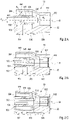
- FIG. 3A to 3C a second embodiment variant is shown, in which the air/fuel supply arrangements 50 are designed starting from a high-calorific design point (a design operating point for operation with a high-calorific design fuel, for example natural gas with a calorific value of just under 50 MJ/kg).
- the flow cross section at the fuel orifice 510, or here the diameter d 3 is reduced compared to the flow cross section or the diameter d 2 of the fuel channel 502 by the Accelerate fuel flow to a desired velocity at fuel orifice 510.
- the bypass channels 526 here run radially-axially, for example, inclined at an angle ⁇ with respect to the central axis M.
- the angle ⁇ is ( Figures 2A to 2C ) e.g. B. between 15 ° and 45 ° (open ⁇ direction upstream).
- the angle ⁇ and the total flow cross-sections of the bypass channels 526 and/or the bypass openings 528 are designed with respect to the high-calorific design point in the first exemplary embodiment and with respect to the low-calorific design point in the second exemplary embodiment.
- the design is such that the velocities at the fuel orifices 510 in the high-caloric or low-caloric design point is matched to the velocities in the low-caloric or high-caloric design point, ie the velocities are similar.
- the "low calorific/high calorific" velocity ratio at the fuel orifices 510 is less than a factor of 2, preferably less than a factor of 1.5.
- the second air/fuel supply arrangement 60 (cf. 1 and figure 5 , 6A, B ) is designed to supply the fresh gas components, air and fuel, to the second combustion chamber 26 in a swirling flow, ie with a tangential directional component.
- the air/fuel supply arrangement 60 comprises a mixing chamber 608 which is formed on the bottom side in the inner wall, upstream, of the combustion chamber 26 so that it opens into the combustion chamber 26 downstream with an outlet 612 .
- the mixing chamber 608 is arranged centrally, on the longitudinal axis L, and is embodied symmetrically to this, in particular cylindrically.
- the air ducts 604 with air openings 610, three in number here by way of example, open out into the mixing chamber 608 in the wall 609 on the peripheral side.
- the air channels 604 form a flow connection between the air distribution space 30 and the mixing space 608 and form separate flow sections of the flow path of the air, here by way of example for the pilot stage.
- the air ducts 604 have a circular cross section, for example.
- the air ducts 604 run, for example, axially constant, in a plane perpendicular to the longitudinal axis L, and are aligned tangentially to the cylindrical mixing space 608 in order to impress the exiting air flow with a tangential directional component for generating the swirl flow.
- the alignment could also have a radial directional component.
- the distribution area 40 is fed by the second fuel feed 36 arranged centrally on the longitudinal axis L.
- FIG. The central arrangement of the fuel feed 36 and the distributor area 40 with its arrangement adjacent to the rear of the bottom wall 626 advantageously enables cooling of the bottom wall 626 by means of the supplied fuel flow, which impinges on the rear of the bottom wall 626 and cools it in the manner of impingement cooling.
- the fuel orifices 614 form a group of first supply openings, with the fresh gas components fuel and air being brought together in the mixing space 608 .
- further flow sections, formed by second fuel channels 603, are present, which each open into the mixing chamber 608 of a group via further feed openings, formed by second fuel ports 616.
- the second fuel channels 603 are aligned axially with respect to the longitudinal axis L, although they can also have a radial component.
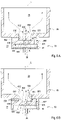
- Figure 6A shows the operation in the low calorific design point, with high fuel mass flow.
- the fuel flows through the distribution area 40.
- the flow cross sections of the second fuel channels 603 or the second fuel openings 616 or the total flow cross section (sum of the flow cross sections) is selected in such a way that there is a high pressure loss within the second fuel channels 603 at the low-calorific design point.
- the pressure loss caused by the design is so high that a proportion, for example between 90% and 30%, of the fuel flows into the mixing chamber 608 via the first fuel channels 602, the fuel at the first fuel ports 614 having a speed of z. B. 10% to 30% of the air flow at the air ports 610 has.
- the rotation of the swirl flow is thus driven by the high fuel mass flows.
- the other portion of the fuel e.g. B. 10% to 70%, flows via the second fuel channels 603.
- the burner system 1 can be operated stably and reliably with both low-calorific and high-calorific fuels and variants in between. Since the adjusted flow through the air/fuel supply arrangements is set due to the changing pressure conditions with the changing calorific value or Wobbe index without changing the (burner head) geometry, no adjustment or regulation via a control or regulating device is advantageously required.
Landscapes
- Engineering & Computer Science (AREA)
- Chemical & Material Sciences (AREA)
- Combustion & Propulsion (AREA)
- Mechanical Engineering (AREA)
- General Engineering & Computer Science (AREA)
- Gas Burners (AREA)
- Engine Equipment That Uses Special Cycles (AREA)
- Feeding And Controlling Fuel (AREA)
- Combustion Of Fluid Fuel (AREA)
Description
Die Erfindung betrifft ein Brennersystem zur Erzeugung von Heißgas in einer Gasturbinenanlage, mit einer Brennkammer, die einen entlang einer Längsachse ausgerichteten Brennraum umfasst, und mit einem Brennerkopf mit zumindest einer Oxidator-/Brennstoffzufuhranordnung zur Zufuhr von Oxidator und Brennstoff als Frischgaskomponenten in die Brennkammer, umfassend jeweils einen Strömungspfad für Brennstoff und Oxidator zu deren Zuführung in den Brennraum, wobei die Strömungspfade stromauf eines Mischraumes jeweils getrennte Strömungsabschnitte, zur getrennten Führung der Frischgaskomponenten, aufweisen, und die Strömungspfade in den Mischraum zusammengeführt sind, und zumindest eine erste Zuführöffnung zum Zuführen von Brennstoff in den Mischraum. Die Erfindung betrifft ferner ein entsprechendes Verfahren zur Erzeugung von Heißgas in einer Gasturbinenanlage.The invention relates to a burner system for generating hot gas in a gas turbine system, with a combustion chamber that includes a combustion chamber aligned along a longitudinal axis, and with a burner head with at least one oxidizer/fuel supply arrangement for supplying oxidizer and fuel as fresh gas components into the combustion chamber one flow path each for fuel and oxidizer for feeding them into the combustion chamber, with the flow paths upstream of a mixing chamber each having separate flow sections for separate routing of the fresh gas components, and the flow paths in the mixing chamber are combined, and at least one first feed opening for feeding fuel into the mixing room. The invention also relates to a corresponding method for generating hot gas in a gas turbine system.
Ein derartiges Brennersystem geht beispielsweise aus der
In jüngster Zeit wächst das Interesse, neben konventionellen Brennstoffen, wie z. B. Erdgas, weitere Brennstoffe mit unterschiedlichen Zusammensetzungen energetisch zu nutzen. Derartige Brennstoffe stellen z. B. Synthesegas aus der Biomassevergasung, Klärgas, Deponiegas, Biogas, Grubengas oder Erdölbegleitgas dar. Die energetische Umsetzung der Brennstoffe kann beispielsweise in Gasturbinenanlagen, insbesondere in Mikrogasturbinenanlagen, geschehen, wobei die Brennstoffe in einem Verbrennungsprozess zu einem Heißgas mit heißem Abgas umgesetzt werden. Dazu müssen die Brennstoffe zuverlässig, effizient und schadstoffarm verbrannt werden.In recent times, interest has been growing in addition to conventional fuels such as e.g. B. natural gas, to use other fuels with different compositions energetically. Such fuels provide z. B. synthesis gas from biomass gasification, sewage gas, landfill gas, biogas, mine gas or associated gas. The energetic conversion of the fuels can, for example, in gas turbine plants, in particular in micro gas turbine systems, where the fuels are converted into a hot gas with hot exhaust gas in a combustion process. To do this, the fuels must be burned reliably, efficiently and with low emissions.
Die unterschiedlichen Brennstoffe können sich in ihrer Zusammensetzung deutlich unterscheiden. So weist z. B. Erdgas einen hohen Anteil an Methan als Bestandteil auf, während ein typisches Synthesegas neben Wasserstoff und gegebenenfalls weitere brennbaren Komponenten (z. B. Kohlenmonoxid, Methan) in der Regel einen hohen Inertgasanteil (insbesondere Kohlendioxid und Stickstoff) enthält. Daher weisen die Brennstoffe Unterschiede in ihren Verbrennungseigenschaften, wie z. B. Flammengeschwindigkeit und Zündverzugszeit, und in ihren Heizwerten bzw. ihren Wobbe-Indizes (als Größe zur Beurteilung der Austauschbarkeit von Brenngasen) auf. So ist z. B. Erdgas, mit einem massenspezifischen Heizwert von knapp unter 50 MJ/kg, den hochkalorischen Brennstoffen zuzuordnen, wohingegen ein typisches Synthesegas als niederkalorischer Brennstoff beispielsweise einen massenspezifischen Heizwert von ca. 5 MJ/kg oder darunter aufweisen kann. Mittelkalorische Brennstoffe weisen Heizwerte zwischen diesen Extrema auf. Somit ist bei Verwendung eines derartigen, niederkalorischen, Synthesegases im Vergleich zu - hochkalorischem - Erdgas zur Erzielung einer entsprechenden Leistung ein etwa zehnfach größerer Brennstoffmassenstrom notwendig. Diese unterschiedlichen Eigenschaften erschweren die Nutzung unterschiedlicher Brennstoffqualitäten in einem einzigen Brennersystem.The different fuels can differ significantly in their composition. So z. B. Natural gas has a high proportion of methane as a component, while a typical synthesis gas usually contains a high proportion of inert gas (especially carbon dioxide and nitrogen) in addition to hydrogen and possibly other combustible components (e.g. carbon monoxide, methane). The fuels therefore have differences in their combustion properties, e.g. B. flame speed and ignition delay time, and in their calorific values or their Wobbe indices (as a parameter for assessing the interchangeability of fuel gases). So e.g. B. natural gas, with a mass-specific calorific value of just under 50 MJ / kg, to be assigned to the high-calorific fuels, whereas a typical synthesis gas as a low-calorific fuel, for example, can have a mass-specific calorific value of about 5 MJ / kg or less. Medium-calorific fuels have calorific values between these extremes. Thus, when using such a low-calorific synthesis gas, compared to—high-calorific—natural gas, an approximately tenfold greater fuel mass flow is necessary to achieve a corresponding performance. These different properties make it difficult to use different fuel qualities in a single burner system.
Ein bekanntes Vorgehen zum Einsatz sowohl hochkalorischer als auch niederkalorischer Brennstoffe in einem einzigen Brennersystem ist deren separate Einbringung. Dabei werden die unterschiedlichen Brennstoffe über getrennte Zuführungen eingebracht, die jeweils auf die bestimmten Eigenschaften des Brennstoffes ausgelegt sind. Eine andere Vorgehensweise ist der Austausch und/oder die Anpassung der Brennstoffdüsen bzw. -kanäle unter Änderung der Geometrie. Dies ist jedoch aufwendig und erlaubt meist keine Anpassung während des laufenden Brennerbetriebs.A known procedure for using both high-calorific and low-calorific fuels in a single burner system is to introduce them separately. The different fuels are introduced via separate feeds, each of which is designed for the specific properties of the fuel. Another approach is to replace and/or adapt the Fuel nozzles or channels with a change in geometry. However, this is expensive and usually does not allow any adjustment during ongoing burner operation.
Die
Brennersysteme insbesondere zum Betrieb mit mittel- oder niederkalorischen Brennstoffen sind in der
Ein Brennersystem basierend auf dem Prinzip eines rezirkulationsstabilisierten Strahlflammenbrenners ist der
Eine Mischungsvorrichtung beispielsweise zum Einsatz in einem rezirkulationsstabilisierten Strahlflammenbrenner ist in der
Die
Die
In der
Die
Die
Der Erfindung liegt die Aufgabe zugrunde, ein Brennersystem sowie ein Verfahren zur Erzeugung von Heißgas bereitzustellen, das einen zuverlässigen, schadstoffarmen und effizienten Betrieb mit sowohl hochkalorischen als auch niederkalorischen Brennstoffen bei vergleichsweise geringem Aufwand ermöglicht.The object of the invention is to provide a burner system and a method for generating hot gas that enables reliable, low-emission and efficient operation with both high-calorific and low-calorific fuels at comparatively little expense.
Die Aufgabe wird durch ein Brennersystem mit den Merkmalen des Anspruchs 1 oder des Anspruchs 2 oder ein Verfahren mit den Merkmalen des Anspruchs 17 gelöst.The object is achieved by a burner system having the features of claim 1 or
Bei dem Brennersystem gemäß Anspruch 1 oder Anspruch 2 ist vorgesehen, dass die Oxidator-/Brennstoffzufuhranordnung zumindest einen weiteren Strömungsabschnitt mit einer weiteren Zuführöffnung umfasst, über den ein Anteil einer der Frischgaskomponenten zur Zuführung in den Brennraum in einen Strömungsabschnitt mit der anderen Frischgaskomponente zuführbar ist, wobei der weitere Strömungsabschnitt derart angeordnet und ausgebildet ist, dass der Anteil der Frisch 4, gaskomponente, der über den weiteren Strömungsabschnitt strömt, bei unveränderter Geometrie mit dem Heizwert des Brennstoffes aufgrund eines sich ändernden Druckverhältnisses veränderbar ist.In the burner system according to claim 1 or
Der Anteil bezieht sich z. B. auf den gesamten, durch die Oxidator-/Brennstoffzufuhranordnung strömenden Massen- bzw. Volumenstrom des entsprechenden Frischgases. Der weitere Strömungsabschnitt ist insbesondere derart angeordnet, dass die Aufteilung des entsprechenden Frischgaskomponenten-Stroms in zumindest zwei Anteile innerhalb des Brennerkopfes erfolgt, d. h. der weitere Strömungsabschnitt zweigt innerhalb des Brennerkopfes aus dem/den getrennten Strömungsabschnitt/en ab.The share refers z. B. on the total, flowing through the oxidizer / fuel supply arrangement mass or volumetric flow of the corresponding fresh gas. The further flow section is arranged in particular in such a way that the corresponding fresh gas component flow is divided into at least two parts within the burner head, i. H. the further flow section branches off within the burner head from the separate flow section(s).
Der Strömungsabschnitt mit der anderen Frischgaskomponente kann beispielsweise einer der Strömungsabschnitte von Brennstoff oder Oxidator stromauf des Mischraums sein. Z. B. werden die Strömungspfade der Frischgaskomponenten stromauf der weiteren Zuführöffnung getrennt geführt und stromab der weiteren Zufuhröffnung /zunächst teilweise zusammengeführt, in einem gemeinsamen und einem (weiterhin getrennten) Strömungsabschnitt, bevor sie wiederum stromab der ersten Zufuhröffnung in dem Mischraum als gemeinsamen Strömungsabschnitt vollständig zusammengeführt werden. Die Zusammenführung kann somit stufenartig nacheinander erfolgen, wobei die weitere Zuführöffnung stromauf der ersten Zuführöffnung angeordnet ist. Insbesondere alternativ kann der Strömungsabschnitt mit der anderen Frischgaskomponente durch den Mischraum gebildet sein, wobei insbesondere ein Anteil des Brennstoffes über den getrennten Strömungsabschnitt mit der ersten Zuführöffnung und der andere Anteil über den (parallel passierbaren) weiteren Strömungsabschnitt und die weitere Zuführöffnung in den Mischraum strömen kann. Dabei münden der getrennte Strömungsabschnitt mit der ersten Zuführöffnung und der weitere Strömungsabschnitt parallel passierbar in den Mischraum. In demselben Brennersystem kann sowohl die eine als auch die andere Alternative vorhanden sein.The flow section with the other fresh gas component can be, for example, one of the flow sections of fuel or oxidizer upstream of the mixing space. For example, the flow paths of the fresh gas components are routed separately upstream of the further feed opening and are partially combined downstream of the further feed opening/initially in a common and a (further separate) flow section before they turn downstream of the first feed opening are completely brought together in the mixing chamber as a common flow section. The merging can thus take place in stages one after the other, with the further feed opening being arranged upstream of the first feed opening. Particularly alternatively, the flow section with the other fresh gas component can be formed by the mixing chamber, in which case in particular a proportion of the fuel can flow via the separate flow section with the first feed opening and the other proportion can flow into the mixing chamber via the further flow section (which can be passed in parallel) and the further feed opening . In this case, the separate flow section with the first feed opening and the further flow section open into the mixing chamber so that they can be passed in parallel. Both alternatives can exist in the same burner system.
Der Mischraum ist in einer Ausbildungsvariante mit einer (zumindest teilweisen) Vormischung der Frischgase vor Einbringung in die Brennkammer ein Teil des Brennerkopfes, insbesondere der Oxidator-/Brennstoffzufuhranordnung, wobei er einen gemeinsamen Strömungsabschnitt bildet. Bei einer ebenfalls möglichen Ausbildungsvariante mit einer nicht vorgemischten Einbringung in die Brennkammer entspricht der Mischraum einem Bereich des Brennraums.In a design variant with (at least partial) premixing of the fresh gases before introduction into the combustion chamber, the mixing chamber is part of the burner head, in particular the oxidizer/fuel supply arrangement, forming a common flow section. In a design variant that is also possible with a non-premixed introduction into the combustion chamber, the mixing chamber corresponds to a region of the combustion chamber.
Die erste und die weitere Zuführöffnung können auch Gruppen von ersten und weiteren Zufuhröffnungen (und/oder diesen zugeordneten Strömungsabschnitten) sein, die z. B. in unterschiedlichen (Strömungs-) Bereichen angeordnet sind, wobei die Gruppen z. B. jeweils nach einander entsprechenden Auslegungskriterien ausgelegt sind und/oder eine einander entsprechende Funktion erfüllen. Hingegen unterscheiden sich die erste/n und die weitere/n Zuführöffnung/en voneinander z. B. durch ihre Auslegungskriterien und/oder Funktion.The first and further feed openings can also be groups of first and further feed openings (and/or flow sections associated with them) which, for. B. in different (flow) areas are arranged, the groups z. B. are each designed according to corresponding design criteria and / or fulfill a corresponding function. In contrast, the first and the other / n feed opening / s differ from each other z. B. by their design criteria and / or function.
Die Anordnung und/oder Ausbildung des weiteren Strömungsabschnitts ist derart, dass sich der Anteil bei Einbringung von Brennstoffen mit einem unterschiedlichen Heizwert (bzw. einem unterschiedlichen Wobbe-Index) aufgrund sich ändernder aerodynamischer Verhältnisse, insbesondere der Druckverhältnisse, ändert. Die Geometrie bleibt unverändert, insbesondere bleiben die Strömungsquerschnitte der Strömungsabschnitte konstant. Auf eine Volumenstromregulierung mittels Stelleinrichtungen, insbesondere Ventilen, kann verzichtet werden. So kann vorteilhaft die Zuführung unterschiedlicher Brennstoffe über dieselben Oxidator-/Brennstoffzufuhranordnungen erfolgen. Dies erlaubt vorteilhaft den Einsatz wechselnder Brennstoffe und/oder einen Mischbetrieb, z. B. mit einer kontinuierlichen Änderung der Brennstoffzusammensetzung, mit geringem Aufwand und während des laufenden Betriebes.The arrangement and / or design of the other flow section is such that the proportion when introducing fuel with a different calorific value (or a different Wobbe index) due to changing aerodynamic Conditions, especially the pressure conditions, changes. The geometry remains unchanged, in particular the flow cross sections of the flow sections remain constant. There is no need to regulate the volume flow by means of adjusting devices, in particular valves. In this way, different fuels can advantageously be supplied via the same oxidizer/fuel supply arrangements. This advantageously allows the use of changing fuels and/or mixed operation, e.g. B. with a continuous change in the fuel composition, with little effort and during operation.
In einem Verfahren zur Auslegung kann z. B. wie folgt vorgegangen werden, um zu dem erfindungsgemäßen Brennersystem zu gelangen: Ausgehend von einem bekannten, gattungsgemäßen Brennersystem wird/werden innerhalb der getrennten Strömungsabschnitte von Oxidator und Brennstoff eine oder mehrere Paarung/en von Orten lokalisiert, an dem/denen sich die Druckdifferenz und/oder das Druckverhältnis zwischen einem hochkalorischen und einem niederkalorischen Auslegungspunkt zu dem Strömungsabschnitt mit der jeweiligen anderen Frischgaskomponente (Brennstoff oder Oxidator) ändert. Dies kann z. B. über eine Druckermittlung mittels computergestützter Strömungssimulation und/oder experimentell geschehen, wobei z. B. die Massen- bzw. Volumenströme entsprechend der Auslegungsbetriebspunkte eingestellt werden. Diese Paarung/en von Orten miteinander verbindend, wird/werden nun ein/mehrere weitere/r Strömungsabschnitt/e mit einer weiteren Zuführöffnung angeordnet. Der (jeweilige) weitere Strömungsabschnitt wird entsprechend der gewünschten Aufteilung bzw. Anteile ausgelegt, insbesondere angeordnet und/oder ausgebildet (z. B. mit entsprechendem Strömungsquerschnitt). Dabei kann z. B. (zunächst) eine überschlägige Druckverlustberechnung und/oder (anschließend) eine iterative Annäherung an ein Auslegungsziel, z. B. mittels computergestützter Strömungssimulation und/oder experimentell, erfolgen. Das Auslegungsziel kann beispielsweise die Aufrechterhaltung eines bestimmten Geschwindigkeitsbereiches zwischen den verschiedenen Auslegungspunkten darstellen.In a method of interpretation z. B. proceed as follows to arrive at the burner system according to the invention: Based on a known generic burner system, one or more pairings of locations is/are located within the separate flow sections of oxidizer and fuel at which the pressure difference and/or the pressure ratio changes between a high-calorific and a low-calorific design point to the flow section with the respective other fresh gas component (fuel or oxidizer). This can e.g. B. via a pressure determination using computer-aided flow simulation and / or done experimentally, with z. B. the mass or volume flows can be adjusted according to the design operating points. Connecting this pairing of locations to one another, one or more further flow section(s) with a further feed opening is/are now arranged. The (respective) further flow section is designed, in particular arranged and/or formed (e.g. with a corresponding flow cross section) according to the desired division or proportions. In doing so, e.g. B. (initially) an approximate pressure drop calculation and/or (subsequently) an iterative approach to a design goal, e.g. B. by means of computer-aided flow simulation and / or experimentally. The design goal can be, for example, maintaining a certain speed range between the different design points.
In einer bevorzugten Ausbildungsvariante ist als Auslegungsziel vorgesehen, dass der Anteil derart veränderbar ist, dass die Geschwindigkeiten an der ersten und/oder an der weiteren Zuführöffnung zwischen einem niederkalorischen Auslegungspunkt und einem hochkalorischen Auslegungspunkt maximal um den Faktor 2 (Geschwindigkeit mit niederkalorischem zu Geschwindigkeit mit hochkalorischem Brennstoff), insbesondere maximal um den Faktor 1,5, vorzugsweise maximal um den Faktor 1,2, voneinander abweichen, d. h. die Geschwindigkeiten in den unterschiedlichen Auslegungspunkten sind ähnlich zueinander. Der "niederkalorische Auslegungspunkt" entspricht einem Auslegungsbetriebspunkt mit einem niederkalorischen Auslegungsbrennstoff, beispielsweise einem Synthesegas, mit einem massenspezifischen Heizwert von ca. 5 MJ/kg. Der "hochkalorische Auslegungspunkt " entspricht einem Auslegungsbetriebspunkt mit einem hochkalorischen Auslegungsbrennstoff, beispielsweise einem Erdgas, mit einem massenspezifischen Heizwert von knapp 50 MJ/kg. Die thermischen Leistungen der beiden Auslegungspunkte entsprechen einander, wobei sie maschinenseitig vorgeben sind. Bei einer Mikrogasturbinenanordnung, bei der das erfindungsgemäße Brennersystem z. B. vorteilhaft eigesetzt werden kann, kann die thermische Leistung z. B. bis 1 MW oder 500 kW, z. B. rund 300 kW betragen. Die Luftzahl bzw. das Verbrennungsluftverhältnis entspricht beispielsweise dem bei einem bekannten, gattungsgemäßen Brenner-system und kann z. B. zwischen 1,4 und 3,4 betragen. Die Brennstoffzusammensetzungen in dem niederkalorischen und hochkalorischen Auslegungspunkt stellen vorzugsweise Extrema bezüglich des Heizwertes dar, zwischen denen sich die Heizwerte der Brennstoffzusammensetzungen im Betrieb bewegen. Die (wie vorstehend definiert) ähnlichen Geschwindigkeiten sind erreichbar durch die Auslegung und/oder Anordnung des weiteren Strömungsabschnittes mit der weiteren Zuführöffnung. Die Auslegung erfolgt vorzugsweise, wie heutzutage üblich, über computergestützte Strömungssimulation. Auf diese Weise wird erreicht, dass insbesondere diejenigen Geschwindigkeiten, die den Verbrennungsprozess in dem Brennkammersystem entscheidend beeinflussen, mit unterschiedlichen Brennstoffen (zumindest in vorstehend genanntem Maße) ähnlich zueinander bleiben. So können bestimmte Betriebscharakteristika, beispielsweise (zumindest teil- bzw. bereichsweise) die Einmischung von Brennstoff in den Oxidator, in beiden Auslegungspunkten angeglichen werden. Dies trägt zu einem stabilen, emissionsarmen und effizienten Verbrennungsprozess mit sowohl nieder-, mittel- als auch hochkalorischen Brennstoffen bei.In a preferred variant of the design, the design goal is that the proportion can be changed in such a way that the speeds at the first and/or at the further feed opening between a low-calorific design point and a high-calorific design point by a maximum of a factor of 2 (speed with low-calorific to speed with high-calorific Fuel), in particular by a maximum of a factor of 1.5, preferably a maximum of a factor of 1.2, deviate from one another, ie the speeds in the different design points are similar to one another. The “low-calorific design point” corresponds to a design operating point with a low-calorific design fuel, for example a synthesis gas, with a mass-specific calorific value of approx. 5 MJ/kg. The “high-calorific design point” corresponds to a design operating point with a high-calorific design fuel, for example natural gas, with a mass-specific calorific value of just under 50 MJ/kg. The thermal outputs of the two design points correspond to each other, although they are specified on the machine side. In a micro gas turbine arrangement in which the burner system according to the invention z. B. can be used advantageously, the thermal power z. up to 1 MW or 500 kW, e.g. B. be around 300 kW. The air ratio or the combustion air ratio corresponds, for example, to that of a known, generic burner system and can, for. B. be between 1.4 and 3.4. The fuel compositions in the low-calorific and high-calorie design point preferably represent extremes with regard to the calorific value, between which the calorific values of the fuel compositions move during operation. The similar speeds (as defined above) can be achieved by the design and/or arrangement of the further flow section with the further feed opening. The design is preferably carried out, as is common nowadays, using computer-aided flow simulation. What is achieved in this way is that, in particular, those speeds which decisively influence the combustion process in the combustion chamber system are similar to one another with different fuels (at least to the extent mentioned above). stay. In this way, certain operating characteristics, for example (at least in part or in certain areas) the mixing of fuel into the oxidizer, can be matched in both design points. This contributes to a stable, low-emission and efficient combustion process with both low, medium and high-calorific fuels.
In einer bevorzugten Ausbildungsvariante des Brennersystems gemäß Anspruch 1 weist die Oxidator-/Brennstoffzufuhranordnung einen Oxidatorkanal mit einem Austritt zur Mündung in die Brennkammer auf, wobei der Oxidatorkanal mit einem, den Austritt umfassenden, Ausströmabschnitt entlang einer Mittelachse M ausgerichtet ist, die im Wesentlichen axial, parallel zu der Längsachse, verläuft. Der Oxidatorkanal bildet einen Strömungspfad für Oxidator, der in einem stromauf liegenden Abschnitt den Oxidator getrennt führt. Das stromauf gerichtete Ende des Oxidatorkanals kann insbesondere mit einem Oxidator-Verteilerraum des Brennerkopfes in Strömungsverbindung stehen, sodass der Oxidatorkanal eine Strömungsverbindung für den Oxidator zwischen dem Oxidator-Verteilerraum und dem Brennraum bildet. Der Oxidatorkanal kann insbesondere düsenartig ausgebildet sein. Durch die axiale Anordnung kann der Oxidator in die Brennkammer mit einem hohen axialen Impuls eingebracht werden, so dass sich in dem Brennraum eine ausgeprägte Rezirkulationszone ausbildet, die die Verbrennung stabilisiert, wie bei einem rezirkulationsstabilisierten Strahlflammenbrenner (auch bekannt als "FLOX-Brenner") üblich. Eine derartige Ausbildung erlaubt einen stabilen, emissionsarmen Verbrennungsprozess.In a preferred embodiment variant of the burner system according to claim 1, the oxidizer/fuel supply arrangement has an oxidizer duct with an outlet to the mouth into the combustion chamber, the oxidizer duct being aligned with an outflow section comprising the outlet along a central axis M, which is essentially axial parallel to the longitudinal axis. The oxidizer channel forms an oxidizer flow path that guides the oxidizer separately in an upstream portion. The upstream end of the oxidizer channel can in particular be in flow communication with an oxidizer distribution space of the burner head, so that the oxidizer channel forms a flow connection for the oxidizer between the oxidizer distribution space and the combustion chamber. The oxidizer channel can in particular be designed in the manner of a nozzle. Due to the axial arrangement, the oxidizer can be introduced into the combustion chamber with a high axial impulse, so that a pronounced recirculation zone is formed in the combustion chamber, which stabilizes the combustion, as is usual with a recirculation-stabilized jet flame burner (also known as "FLOX burner") . Such a design allows a stable, low-emission combustion process.
In einer bevorzugten Ausbildungsvariante des Brennersystems gemäß Anspruch 1 weist die Oxidator-/Brennstoffzufuhranordnung einen von einer Wandung umgrenzten Brennstoffkanal auf, der zumindest mit einem Endabschnitt in dem Oxidatorkanal parallel, insbesondere koaxial, zu dem Oxidatorkanal verlaufend ausgebildet ist und der mit einer Brennstoffmündung innerhalb des Oxidatorkanals oder an dessen Austritt mündet, wobei die Brennstoffmündung die erste Zuführöffnung bildet. In dem Brennstoffkanal ist stromauf der Brennstoffmündung (und ggf. stromauf der weiteren Zuführöffnung) der getrennte Abschnitt des Brennstoff-Strömungspfades gebildet. Der Brennstoffkanal kann insbesondere eine Strömungsverbindung zwischen einem Brennstoff-Verteilerbereich und dem Mischraum bilden. Durch die derartige Ausbildung des Brennstoffkanals mit der Brennstoffmündung kann der Brennstoff koaxial in die Luftströmung zugegeben werden, was eine symmetrische, gleichmäßige Brennstoffeinmischung in den Oxidator und so einen gleichmäßigen, stabilen Verbrennungsprozess mit geringen Emissionen unterstützt.In a preferred variant of the burner system according to claim 1, the oxidizer/fuel supply arrangement has a fuel channel which is delimited by a wall and which has at least one end section in the oxidizer channel running parallel, in particular coaxially, to the oxidizer channel and which has a fuel opening inside the oxidizer channel or opens out at its outlet, the fuel orifice forming the first feed opening. In the fuel channel, upstream of the fuel orifice (and possibly upstream of the other Feed opening) formed the separate portion of the fuel flow path. The fuel channel can in particular form a flow connection between a fuel distribution area and the mixing space. By designing the fuel channel with the fuel orifice in this way, the fuel can be added coaxially into the air flow, which supports symmetrical, uniform fuel mixing in the oxidizer and thus a uniform, stable combustion process with low emissions.
In einer Ausbildungsvariante des Brennersystems gemäß Anspruch 1 weist die Brennstoffmündung einen Strömungsquerschnitt, insbesondere mit einem Durchmesser d3, auf, der gegenüber dem Strömungsquerschnitt, insbesondere mit einem Durchmesser d2, des stromauf verlaufenden Brennstoffkanals reduziert ist. Vorzugsweise ist der Strömungsquerschnitt der Brennstoffmündung derart ausgelegt, dass sich dort in dem hochkalorischen Auslegungspunkt eine Geschwindigkeit ähnlich der Geschwindigkeit der Frischgase an dem Austritt des Oxidatorkanals in die Brennkammer ergibt. "Ähnlich" bedeutet hierbei, beispielsweise zwischen +/- 50 %, vorzugsweise zwischen +/- 20 %, besonders bevorzugt zwischen +/- 10 % der Geschwindigkeit an dem Austritt. Die ähnliche Geschwindigkeit bewirkt eine hohe Stabilität bei der Brennstoffeinmischung unter Vermeidung von Ablösungen, die zu einer instabilen Verbrennung bis hin zu thermoakustischen Schwingungen führen können.In a variant embodiment of the burner system according to claim 1, the fuel orifice has a flow cross section, in particular with a diameter d 3 , which is reduced compared to the flow cross section, in particular with a diameter d 2 , of the fuel channel running upstream. The flow cross-section of the fuel orifice is preferably designed in such a way that a speed similar to the speed of the fresh gases at the exit of the oxidizer channel into the combustion chamber results there at the high-calorific design point. "Similar" here means, for example, between +/-50%, preferably between +/-20%, particularly preferably between +/-10% of the speed at the outlet. The similar speed results in high stability when mixing the fuel while avoiding detachments, which can lead to unstable combustion and even thermoacoustic oscillations.
Alternativ weist die Brennstoffmündung einen Strömungsquerschnitt, insbesondere mit einem Durchmesser d3, auf, der dem Strömungsquerschnitt, insbesondere mit einem Durchmesser d2, des stromauf verlaufenden Brennstoffkanals entspricht. Der Strömungsquerschnitt ist z. B. derart, dass sich dort in dem niederkalorischen Auslegungspunkt eine Geschwindigkeit ähnlich (wie in vorstehendem Absatz definiert) der Frischgase an dem Austritt des Oxidatorkanals einstellt, mit den vorstehend genannten Vorteilen.Alternatively, the fuel orifice has a flow cross section, in particular with a diameter d 3 , which corresponds to the flow cross section, in particular with a diameter d 2 , of the fuel channel running upstream. The flow cross section is z. B. in such a way that there in the low-caloric design point a speed similar (as defined in the previous paragraph) of the fresh gases sets in at the outlet of the oxidizer channel, with the advantages mentioned above.
Bei dem Brennersystem gemäß Anspruch 1 ist die weitere Zuführöffnung durch zumindest eine Bypassöffnung gebildet, wobei die Bypassöffnung stromauf der Brennstoffmündung in der Wandung ausgebildet ist und wobei der weitere Strömungsabschnitt eine Strömungsverbindung zwischen den Strömungspfaden des Oxidators und des Brennstoffes bildet. In dem Falle, dass eine Frischgaskomponente (Brennstoff oder Oxidator) durch die Bypassöffnung strömt, dient die Bypassöffnung einer teilweisen Zusammenführung der Frischgase stromauf der Brennstoffmündung. Die getrennten Strömungsabschnitte der Strömungspfade sind dann stromauf der Bypassöffnung gelegen. Die vollständige Zusammenführung von Brennstoff und Oxidator erfolgt vorzugsweise weiterhin stromab der Brennstoffmündung. Es hat sich gezeigt, dass durch eine derartige Anordnung der Bypassöffnung, stromauf der Brennstoffmündung, vorteilhaft der Massen- bzw. Volumenstrom, der durch die Brennstoffmündung strömt, zwischen dem hochkalorischen und dem niederkalorischen Auslegungspunkt zumindest teilweise ausgeglichen werden kann. Auf diese Weise können vorteilhaft in dem nieder- und dem hochkalorischen Auslegungspunkt ähnliche Geschwindigkeiten an der Brennstoffmündung erreicht werden, die um weniger als den Faktor 2, insbesondere um weniger als 1,5, vorzugsweise um weniger als 1,2 voneinander abweichen. So können vorteilhaft in den beiden Auslegungspunkten ähnliche Einströmungs- und Einmischungscharakteristika erreicht werden, die eine Voraussetzung für einen stabilen, effizienten und emissionsarmen Betrieb bilden.In the burner system according to claim 1, the further feed opening is formed by at least one bypass opening, the bypass opening being formed in the wall upstream of the fuel orifice and the further flow section forming a flow connection between the flow paths of the oxidizer and the fuel. In the event that a fresh gas component (fuel or oxidizer) flows through the bypass opening, the bypass opening serves to partially combine the fresh gases upstream of the fuel orifice. The separate flow sections of the flow paths are then located upstream of the bypass opening. The complete combination of fuel and oxidizer preferably continues to take place downstream of the fuel orifice. It has been shown that such an arrangement of the bypass opening upstream of the fuel orifice advantageously allows the mass or volume flow which flows through the fuel orifice to be at least partially balanced between the high-calorific and the low-calorific design point. In this way, similar velocities at the fuel orifice can advantageously be achieved in the low-calorific and high-calorific design point, which deviate from one another by a factor of less than 2, in particular by less than 1.5, preferably by less than 1.2. In this way, similar inflow and mixing characteristics can advantageously be achieved in the two design points, which form a prerequisite for stable, efficient and low-emission operation.
Vorzugsweise ist bei dem Brennersystem gemäß Anspruch 1 der Strömungsquerschnitt der Brennstoffmündung derart ausgelegt, dass in dem niederkalorischen Auslegungspunkt oder in dem hochkalorischen Auslegungspunkt die Geschwindigkeit an der Brennstoffmündung zwischen +/- 50 %, vorzugsweise zwischen +/- 20 % der Geschwindigkeit des Frischgasgemisches an dem Austritt in den Brennraum beträgt, wobei der durch die Bypassöffnung strömende Anteil (zumindest im Wesentlichen) gleich null beträgt. In dem entsprechenden Auslegungspunkt ist dann ein Betrieb möglich, bei dem, wie aus dem Stand der Technik bekannt, die Brennstoff- und Oxidatorströme getrennt bis an die Brennstoffmündung heranströmen und dort (vollständig) zusammengeführt werden. Dies ermöglicht vorteilhaft eine einfache Auslegung, ausgehend von einer (z. B. aus dem Stand der Technik bekannten) Konfiguration ohne Bypassöffnung. Der Strömungsabschnitt mit der Bypassöffnung ist derart ausgelegt (ausgebildet und/oder angeordnet), dass mit einem anderen Brennstoff (der einen anderen Heizwert aufweist) ein Anteil an Brennstoff oder Oxidator durch die Bypassöffnung und jeweils in den Strömungspfad mit der anderen Frischgaskomponente strömen kann. Unterschiede in den Brennstoffvolumenströmen lassen sich ausgleichen, zumindest derart, dass die Geschwindigkeit an der Brennstofföffnung wie vorstehend angegeben in einem ähnlichen Bereich bleibt. Die Auslegung erfolgt üblicherweise mithilfe computergestützter Strömungssimulation.In the burner system according to claim 1, the flow cross section of the fuel mouth is preferably designed in such a way that in the low-calorific design point or in the high-calorie design point the velocity at the fuel mouth is between +/- 50%, preferably between +/- 20% of the velocity of the fresh gas mixture at the Leakage into the combustion chamber is, wherein the proportion flowing through the bypass opening is (at least substantially) equal to zero. In the corresponding design point, operation is then possible in which, as is known from the prior art, the fuel and oxidizer streams flow separately up to the fuel orifice and there (completely) be merged. This advantageously enables a simple design, starting from a configuration (eg known from the prior art) without a bypass opening. The flow section with the bypass opening is designed (designed and/or arranged) in such a way that with a different fuel (which has a different calorific value), a proportion of fuel or oxidizer can flow through the bypass opening and into the flow path with the other fresh gas component. Differences in fuel volume flows can be compensated for, at least in such a way that the velocity at the fuel orifice remains in a similar range, as indicated above. The design is usually carried out using computer-aided flow simulation.
Beispielsweise ergibt sich folgende vorteilhafte Verfahrensführung bei einer Auslegung ausgehend von dem niederkalorischen Auslegungspunkt, wobei zweckmäßigerweise die Brennstoffmündung einen Strömungsquerschnitt entsprechend dem Brennstoffkanal aufweist: In dem niederkalorischen Auslegungspunkt, mit dem hohen Brennstoffmassen- bzw. -volumenstrom, strömen Brennstoff und Oxidator getrennt bis an die Brennstoffmündung und werden dort vollständig zusammengeführt. Die Druckverhältnisse in dem Oxidator- und Brennstoffkanal sind in dem niederkalorischen Auslegungspunkt ähnlich, sodass der durch die Bypassöffnung strömende Anteil an Frischgas, hierbei Oxidator, (im Wesentlichen) null beträgt. In dem hochkalorischen Auslegungspunkt, mit dem niedrigen Brennstoffmassen- bzw. -volumen-strom, ergibt sich dann in dem Brennstoffkanal ein geringerer Druckverlust als in dem Oxidatorkanal. Dadurch ergibt sich eine Druckdifferenz zwischen dem Oxidator- und dem Brennstoffkanal. Die Druckdifferenz bewirkt eine Strömung von Oxidator in den Brennstoffkanal durch die Bypassöffnung derart, dass sich die Druckverhältnisse ausgleichen. Durch diesen Oxidatoranteil wird der Massen- bzw. Volumenstrom in dem Brennstoffkanal stromab der Bypassöffnung erhöht, während der Oxidatorstrom verringert wird. Der weitere Strömungsabschnitt mit der Bypassöffnung, insbesondere dessen Winkel und Strömungsquerschnitt, sind derart ausgelegt, dass sich der durch die Bypassöffnung strömende Anteil an Oxidator derart ergibt, dass die Geschwindigkeit an der Brennstoffmündung verglichen mit dem niederkalorischen Auslegungspunkt (wie vorstehend angegeben) ähnlich ist, verbunden mit den vorstehend angegebenen Vorteilen. Insbesondere ist der Gesamtströmungsquerschnitt der Bypassöffnung und/oder des weiteren Strömungsabschnitts geringer als der kleinste Strömungsquerschnitt in dem Brennstoffkanal (mit der Brennstoffmündung), mit z. B. zwischen 10 % und 70 % bzgl. dem kleinsten Querschnitt. Der Anteil an Oxidator kann sich beispielsweise derart ergeben, dass der Oxidatormassenstrom durch den Bypasskanal bis zu dem 5-fachen des Brennstoffmassenstroms entspricht. Es hat sich gezeigt, dass sich bei Brennstoffzusammensetzungen mit einem Heizwert bzw. Wobbe-Index zwischen dem des nieder- und des hochkalorischen Brennstoffes ein entsprechend geringerer Anteil einstellt, der zu den ähnlichen Geschwindigkeiten führt.For example, the following advantageous method results in a design starting from the low-calorific design point, with the fuel orifice expediently having a flow cross section corresponding to the fuel channel: At the low-calorific design point, with the high fuel mass or volume flow, fuel and oxidizer flow separately up to the fuel orifice and are completely merged there. The pressure ratios in the oxidizer and fuel channel are similar in the low-calorific design point, so that the proportion of fresh gas, in this case oxidizer, flowing through the bypass opening is (essentially) zero. At the high-calorific design point, with the low fuel mass or volumetric flow, there is then a lower pressure loss in the fuel channel than in the oxidizer channel. This results in a pressure difference between the oxidizer and the fuel channel. The pressure difference causes oxidizer to flow into the fuel channel through the bypass opening in such a way that the pressure conditions balance out. This proportion of oxidizer increases the mass or volume flow in the fuel channel downstream of the bypass opening, while the oxidizer flow is reduced. The further flow section with the bypass opening, in particular its angle and flow cross section, are designed in such a way that the proportion of oxidizer flowing through the bypass opening results in such a way that the speed at the fuel mouth compared to the low calorific design point (as indicated above), with the advantages indicated above. In particular, the total flow cross section of the bypass opening and/or the further flow section is smaller than the smallest flow cross section in the fuel channel (with the fuel port), with z. B. between 10% and 70% of the smallest cross-section. The proportion of oxidizer can result, for example, in such a way that the oxidizer mass flow through the bypass channel corresponds to up to 5 times the fuel mass flow. It has been shown that in the case of fuel compositions with a calorific value or Wobbe index between that of the low-calorific and the high-calorific fuel, a correspondingly lower proportion is established, which leads to similar speeds.
Bei einer Auslegung ausgehend von dem hochkalorischen Auslegungspunkt ergibt sich beispielsweise folgende vorteilhafte Verfahrensführung, wobei zweckmäßigerweise die Brennstoffmündung einen reduzierten Strömungsquerschnitt der Brennstoffmündung gegenüber dem Brennstoffkanal aufweist: In dem hochkalorischen Auslegungspunkt, mit dem niedrigen Brennstoffmassen- bzw. -volumenstrom, strömen Brennstoff und Oxidator getrennt bis an die Brennstoffmündung und werden dort vollständig zusammengeführt. Die Druckverhältnisse in dem Oxidator- und Brennstoffkanal sind in dem hochkalorischen Auslegungspunkt ähnlich. Zudem ergibt sich aufgrund der Umströmung des Brennstoffkanals durch Oxidator eine aerodynamische Versperrung des weiteren Strömungsabschnitts mit der Bypassöffnung. Dadurch beträgt der durch die Bypassöffnung strömende Anteil an Frischgas, hierbei Brennstoff, (im Wesentlichen) null. In dem niederkalorischen Auslegungspunkt, mit dem hohen Brennstoffmassen- bzw. -volumenstrom, ergibt sich in dem Brennstoffkanal ein höherer Druckverlust als in dem Oxidatorkanal, insbesondere aufgrund des reduzierten Strömungsquerschnitts der Brennstoffmündung. Dadurch ergibt sich eine Druckdifferenz zwischen dem Oxidator- und dem Brennstoffkanal, die eine Strömung von Brennstoff in den Oxidatorkanal durch die Bypassöffnung bewirkt, derart, dass sich die Druckverhältnisse ausgleichen. Durch den abströmenden Brennstoffanteil wird der Massen- bzw. Volumenstrom in dem Brennstoffkanal stromab der Bypassöffnung reduziert, während der Volumenstrom in dem Oxidatorkanal erhöht wird. Der weitere Strömungsabschnitt mit der Bypassöffnung, insbesondere dessen Winkel und Strömungsquerschnitt, sind derart ausgelegt, dass sich der durch die Bypassöffnung strömende Anteil an Brennstoff derart ergibt, dass die Geschwindigkeit an der Brennstoffmündung verglichen mit dem hochkalorischen Auslegungspunkt ähnlich (wie vorstehend angegeben) ist. Insbesondere ist der Gesamtströmungsquerschnitt der Bypassöffnung und/oder des weiteren Strömungsabschnitts geringer als der kleinste Strömungsquerschnitt in dem Brennstoffkanal. Der Anteil kann beispielsweise zwischen 30 % und 90 % des gesamten Brennstoffmassenstroms betragen. Es hat sich gezeigt, dass sich bei Brennstoffzusammensetzungen mit einem Heizwert zwischen dem des nieder- und des hochkalorischen Brennstoffes ein entsprechend geringerer Anteil einstellt, der zu den ähnlichen Geschwindigkeiten führt.In a design based on the high-calorific design point, the following advantageous method results, for example, with the fuel orifice expediently having a reduced flow cross section of the fuel orifice compared to the fuel channel: At the high-calorific design point, with the low fuel mass or volume flow, fuel and oxidizer flow separately up to to the fuel orifice and are completely brought together there. The pressure conditions in the oxidizer and fuel channels are similar in the high calorific design point. In addition, due to the oxidizer flowing around the fuel channel, an aerodynamic obstruction of the further flow section with the bypass opening results. As a result, the proportion of fresh gas, here fuel, flowing through the bypass opening is (essentially) zero. At the low-calorie design point, with the high fuel mass or volume flow, there is a higher pressure loss in the fuel channel than in the oxidizer channel, in particular due to the reduced flow cross section of the fuel orifice. This results in a pressure difference between the oxidator and the fuel channel, which causes fuel to flow into the oxidator channel through the bypass opening in such a way that the pressure conditions balance out. The mass or volume flow in the fuel channel downstream of the bypass opening is reduced by the outflowing fuel portion, while the volume flow in the oxidizer channel is increased. The further flow section with the bypass opening, in particular its angle and flow cross-section, are designed in such a way that the proportion of fuel flowing through the bypass opening results in such a way that the velocity at the fuel orifice is similar (as stated above) compared to the high-calorific design point. In particular, the total flow cross section of the bypass opening and/or the further flow section is smaller than the smallest flow cross section in the fuel channel. The proportion can be between 30% and 90% of the total fuel mass flow, for example. It has been shown that in the case of fuel compositions with a calorific value between that of the low- and the high-calorific fuel, a correspondingly lower proportion is established, which leads to similar speeds.
Wenn mehrere Strömungsabschnitte vorhanden sind, die insbesondere symmetrisch zueinander, z. B. drehsymmetrisch um die Mittelachse und axial auf gleicher Höhe, angeordnet sind, lässt sich eine symmetrische Einbringung der einen Frischgaskomponente in die andere Frischgaskomponente erreichen. Dies ist einer gleichmäßigen Einmischung zuträglich, die wiederum eine emissionsarme Verbrennung unterstützt.If several flow sections are present, which are particularly symmetrical to each other, e.g. B. are arranged rotationally symmetrically about the central axis and axially at the same height, a symmetrical introduction of a fresh gas component can be achieved in the other fresh gas component. This promotes even mixing, which in turn supports low-emission combustion.
Bei dem Brennersystem gemäß Anspruch 1 ist vorzugsweise die Bypassöffnung axial innerhalb (bzw. bezüglich) des Oxidatorkanals stromab eines Einströmabschnitts des Oxidatorkanals angeordnet, der vorzugsweise eine derartige axiale Länge aufweist, dass Einlaufeffekte der Oxidatorströmung bei Einströmung in den Oxidatorkanal, insbesondere lokale Strömungsablösungen, an der Bypassöffnung im Wesentlichen abgeklungen sind. "Im Wesentlichen" heißt hierbei, dass die Einströmung in die bzw. aus der Bypassöffnung nicht wesentlich durch instationäre Strömungsphänomene beeinflusst wird. Weiterhin wird durch eine Anordnung in dem Oxidatorkanal vorteilhaft das Risiko einer Rückströmung von Brennstoff in einen Oxidator-Verteilerraum verringert, wie sie beispielsweise bei einer kurzzeitigen Strömungsumkehr in instationären Zuständen (beispielsweise Zündvorgängen etc.) auftreten könnte. Beispielsweise kann die Länge des Einströmabschnitts mindestens dem Durchmesser der Bypassöffnung entsprechen.In the burner system according to claim 1, the bypass opening is preferably arranged axially inside (or with respect to) the oxidizer channel downstream of an inflow section of the oxidizer channel, which preferably has such an axial length that inflow effects of the oxidizer flow when it flows into the oxidizer channel, in particular local flow separations, at the Bypass opening have subsided substantially. “Essentially” here means that the inflow into or out of the bypass opening is not significantly influenced by unsteady flow phenomena. Furthermore, an arrangement in the oxidizer channel advantageously reduces the risk of fuel flowing back into an oxidizer plenum reduced, as could occur, for example, with a short-term flow reversal in transient states (e.g. ignition processes, etc.). For example, the length of the inflow section can correspond at least to the diameter of the bypass opening.
Bei dem Brennersystem gemäß Anspruch 1 ist vorzugsweise die Bypassöffnung axial innerhalb (bzw. bezüglich) des Oxidatorkanals stromauf eines Ausströmabschnitts des Endabschnittes (des Brennstoffkanals) angeordnet, der vorzugsweise eine derartige axiale Länge aufweist, dass Einlaufeffekte bei Einströmung der einen Frischgaskomponente durch die Bypass-öffnung bis zu der Brennstoffmündung im Wesentlichen abgeklungen sind. "Im Wesentlichen" heißt hierbei, dass die Strömung aus der Brennstoffmündung nicht wesentlich durch instationäre Strömungsphänomene beeinflusst wird. So lässt sich in dem stromab gelegenen Mischraum eine gleichmäßige, stabile Einmischung des (gegebenenfalls restlichen) Brennstoffes in den Oxidator erreichen. Die Länge des Ausströmabschnitts kann beispielsweise mindestens 0,5-mal den Innendurchmesser des Brennstoffkanals betragen. Die Länge des Einström- und/oder des Ausströmabschnitts ist insbesondere mithilfe computergestützter Strömungssimulation auslegbar.In the burner system according to claim 1, the bypass opening is preferably arranged axially inside (or with respect to) the oxidizer channel upstream of an outflow section of the end section (of the fuel channel), which preferably has such an axial length that inlet effects occur when the one fresh gas component flows in through the bypass opening have essentially decayed by the fuel orifice. "Substantially" here means that the flow from the fuel orifice is not significantly influenced by unsteady flow phenomena. In this way, a uniform, stable mixing of the (possibly remaining) fuel into the oxidizer can be achieved in the mixing chamber located downstream. The length of the outflow section can be at least 0.5 times the inner diameter of the fuel channel, for example. The length of the inflow and/or outflow section can be designed in particular with the aid of computer-aided flow simulation.
Die gewünschte Strömungsführung mit dem gewünschten, durch die Bypassöffnung strömenden Anteil kann bei dem Brennersystem gemäß Anspruch 1 dadurch unterstützt werden, dass der weitere Strömungsabschnitt einen Bypasskanal in der Wandung umfasst, der radial-axial in einem Winkel bezüglich der Mittelachse (des Brennstoffkanals) verläuft. Der Bypasskanal mündet stromab in die Bypassöffnung. Auf diese Weise wird vorteilhaft eine Strömungsrichtung der einen Frischgaskomponente in die andere, die nicht der Auslegung entspricht, erschwert.The desired flow guidance with the desired proportion flowing through the bypass opening can be supported in the burner system according to claim 1 in that the further flow section comprises a bypass channel in the wall, which runs radially-axially at an angle with respect to the central axis (of the fuel channel). The bypass channel opens downstream into the bypass opening. In this way, a flow direction of one fresh gas component into the other, which does not correspond to the design, is made more difficult.
Dabei kann es in einer Ausbildungsvariante vorteilhaft sein, dass der Winkel zwischen 0° und 90°, insbesondere zwischen 10° und 60°, z. B. zwischen 15° und 45° beträgt. Der Winkel bemisst sich zwischen der Bypasskanal-Längsachse und der Mittelachse (bezüglich des stromauf weisenden Schenkels der Mittelachse). Diese Ausbildung unterstützt eine (gegebenenfalls optionale) Strömung des Oxidators in den Brennstoffkanal und erschwert eine Strömung von Brennstoff nach außen in den Oxidator. Diese Ausbildung des Bypasskanals ist beispielsweise zweckmäßig in Kombination mit einem Strömungsquerschnitt der Brennstoffmündung entsprechend dem Brennstoffkanal, was eine vorteilhafte Auslegung ausgehend von dem niederkalorischen Auslegungspunkt erlaubt.It can be advantageous in one embodiment that the angle is between 0° and 90°, in particular between 10° and 60°, e.g. B. is between 15 ° and 45 °. The angle is measured between the bypass channel longitudinal axis and the Centerline (relative to the upstream leg of the centerline). This design supports a (possibly optional) flow of the oxidizer into the fuel channel and makes it more difficult for fuel to flow out into the oxidizer. This design of the bypass channel is expedient, for example, in combination with a flow cross section of the fuel orifice corresponding to the fuel channel, which allows an advantageous design based on the low-calorific design point.
In einer alternativen Ausbildungsvariante kann es vorteilhaft sein, dass der Winkel zwischen 90° und 180°, insbesondere zwischen 110° und 170°, z. B. zwischen 130° und 165° beträgt. Diese Ausbildung unterstützt eine (je nach Auslegung optionale) Strömung des Brennstoffes in den Oxidatorkanal und erschwert eine Strömung von Oxidator in den Brennstoffkanal. Diese Ausbildung des Bypasskanals ist beispielsweise zweckmäßig in Kombination mit einem reduzierten Strömungsquerschnitt der Brennstoffmündung gegenüber dem Brennstoffkanal, was eine vorteilhafte Auslegung ausgehend von dem hochkalorischen Auslegungspunkt erlaubt.In an alternative embodiment, it can be advantageous for the angle to be between 90° and 180°, in particular between 110° and 170°, e.g. B. is between 130 ° and 165 °. This design supports a flow of fuel into the oxidizer channel (which is optional depending on the design) and makes it more difficult for oxidizer to flow into the fuel channel. This design of the bypass channel is expedient, for example, in combination with a reduced flow cross section of the fuel orifice compared to the fuel channel, which allows an advantageous design based on the high-calorific design point.
Bei dem Brennersystem gemäß Anspruch 1 umfasst der Oxidatorkanal vorzugsweise in seinem axialen Verlauf einen ersten Abschnitt und stromab des ersten Abschnitts einen zweiten Abschnitt, wobei zwischen den beiden Abschnitten eine Querschnittsreduktion angeordnet ist. Dabei ist die Brennstoffmündung axial an der, innerhalb der oder stromab der Querschnittsreduktion angeordnet. Die Querschnittsreduktion kann beispielsweise als Sprung, konisch oder kontinuierlich ausgebildet sein. Durch diese Anordnung der Brennstoffmündung erfolgt die (vollständige) Zugabe des Brennstoffes in die unmittelbar stromab beschleunigte Strömung oder in die bereits beschleunigte Strömung. Dies wirkt vorteilhafterweise einer (ungewollten) Flammenstabilisierung an der Brennstoffmündung entgegen.In the burner system according to claim 1, the oxidizer channel preferably comprises a first section in its axial course and a second section downstream of the first section, with a cross-sectional reduction being arranged between the two sections. In this case, the fuel orifice is arranged axially on, within or downstream of the cross-sectional reduction. The reduction in cross section can be designed, for example, as a step, conical or continuous. This arrangement of the fuel orifice means that the fuel is (completely) added to the flow that is accelerated immediately downstream or to the flow that has already been accelerated. This advantageously counteracts (undesirable) flame stabilization at the fuel orifice.
Bei dem Brennersystem gemäß Anspruch 2 umfasst die Oxidator-/Brennstoffzufuhranordnung einen (ggf. weiteren) Mischraum, der zentral auf der Längsachse angeordnet und symmetrisch zu dieser ausgebildet ist. Der Mischraum ist bodenseitig durch eine, z. B. senkrecht zu der Längsachse L ausgerichtete, Bodenwandung und umfangsseitig von einer Wand begrenzt und z. B. zylindrisch ausgebildet. Stromab mündet der Mischraum mit einem Austritt in den Brennraum. Die Frischgaskomponenten sind dem Mischraum derart zuführbar, dass eine Drall- (bzw. Rotations-) strömung, mit tangentialer Richtungskomponente, erzeugt wird. Die Oxidator-/Brennstoffzufuhranordnung umfasst somit eine Drallbrenneranordnung. Die Oxidator-/Brennstoffzufuhranordnung kann einem einstufigen Brennersystem zugeordnet sein oder einem mehrstufigen, insbesondere einem 2-stufigen, wobei die Oxidator-/Brennstoffzufuhranordnung insbesondere einer Pilotstufe zugeordnet sein kann. Vorteilhaft ist insbesondere eine Kombination mit mehreren Oxidator-/Brennstoffzuordnungen gemäß einer der vorstehenden Ausbildungsvarianten, insbesondere als Hauptstufe. Der Querschnitt des Mischraums senkrecht zur Längsachse ist vorzugsweise kleiner als der des Brennraums. Die Länge des Mischraums in axialer Richtung ist zumindest so groß, dass umfangsseitig Frischgasmündungen eingebracht sein können und vorzugsweise, dass sich bis an den Austritt eine zumindest teilweise Vormischung der Frischgaskomponenten ergibt. Der Mischraum kann, ebenso wie die Brennkammer (insbesondere bei Zuordnung zu einer Pilotstufe), beispielsweise in einen Brennerkopfkörper eingebracht sein.In the burner system according to
Bei dem Brennersystem gemäß Anspruch 2 weist die Oxidator-/Brennstoffzufuhranordnung vorzugsweise zumindest einen Oxidatorkanal auf, der in den Mischraum umfangsseitig mündet und der mit einer tangentialen (und gegebenenfalls einer radialen) Richtungskomponente bezüglich der Längsachse ausgerichtet ist, wobei der Oxidatorkanal dem getrennten Strömungsabschnitt des Oxidators zugeordnet ist. Der Oxidatorkanal bildet beispielsweise eine Strömungsverbindung zwischen dem Luft-Verteilerraum und dem Mischraum. Für eine gleichmäßige, symmetrische Einbringung in den Mischraum sind vorzugsweise mehrere Oxidatorkanäle, beispielsweise drei, vorhanden, die insbesondere drehsymmetrisch um die Längsachse angeordnet sind. Bei Vorhandensein mehrerer Oxidatorkanäle verlaufen und münden diese beispielsweise axial auf gleicher Höhe, in einer Ebene senkrecht zu der Längsachse liegend. So lässt sich der Oxidator-strömung effektiv eine Rotationsbewegung zur Drallerzeugung aufprägen.In the burner system according to
Bei dem Brennersystem gemäß Anspruch 2 ist in einer vorteilhaften Ausgestaltungsvariante der Oxidator-/Brennstoffzufuhranordnung ein Verteilerbereich für Brennstoff zugeordnet, der insbesondere symmetrisch zu der, z. B. zentral auf der Längsachse (bzw. der Längsachse und/oder Symmetrieachse des Mischraums) und/oder angrenzend an die Rückseite der Bodenwandung angeordnet ist. Beispielsweise ist der Verteilerbereich in einem Brennerkopfkörper angeordnet. Insbesondere ist die Querschnittsfläche (senkrecht zur Längsachse) des Verteilerbereichs radial gleich oder größer als die des Mischraums. So lässt sich eine effektive Kühlung der Bodenseite des Mischraums durch den einströmenden Brennstoff erreichen. Insbesondere in Verbindung mit einer zentral auf der Längsachse angeordneten Brennstoffzufuhr, die den Brennstoff z. B. senkrecht zu der Bodenwandung in den Verteilerbereich einbringt, kann der Brennstoff auf die Bodenwandung prallen und so eine effektive Prallkühlung bewirken.In the burner system according to
Ein vorteilhafter Betrieb insbesondere mit niederkalorischem Brennstoff wird bei dem Brennersystem gemäß Anspruch 2 dadurch erreicht, dass die erste Zuführöffnung durch zumindest eine erste Brennstoffmündung gebildet ist, die umfangsseitig in den Mischraum mündet und die das stromabgelegene Ende eines ersten Brennstoffkanals bildet, wobei der Brennstoffkanal mit einem Endabschnitt mit einer tangentialen (und gegebenenfalls radialen) Richtungskomponente bezüglich der Längsachse verläuft. Vorzugsweise ist der Endabschnitt des Brennstoffkanals zu dem Oxidatorkanal gleichgerichtet, d. h. mit entsprechender tangentialer und gegebenenfalls radialer Richtungskomponente. Auf diese Weise kann der Brennstoffstrom vorteilhaft zur Erzeugung der Drallströmung beitragen, was zu einem vergleichsweise geringen Druckverlust führt. Der Brennstoffkanal bildet vorzugsweise eine Strömungsverbindung zwischen dem Verteilerbereich und dem Mischraum. Stromauf des Endabschnittes ist der Brennstoffkanal beispielsweise zur Strömungsverbindung mit dem Verteilerbereich axial ausgerichtet.An advantageous operation, in particular with low-calorific fuel, is achieved with the burner system according to
Dabei sind vorzugsweise, insbesondere bei Vorhandensein mehrerer Oxidator- bzw. Brennstoffkanäle, eine Oxidatormündung des Oxidatorkanals und die erste Brennstoffmündung axial versetzt zueinander angeordnet, wobei die axiale Unterkante der Oxidatormündung stromauf der axialen Unterkante der Brennstoffmündung angeordnet ist. Die Unterkante der Oxidatormündung kann dabei beispielsweise bodenbündig mit der Bodenwandung sein. Auf diese Weise kann der Brennstoffstrom durch die drallbehaftete Oxidatorströmung mitgerissen werden. Im Falle einer Flammenstabilisierung in dem Mischraum bleibt ein gewisser Abstand zu der Bodenwandung bestehen, und insbesondere wird durch die zwischenliegende Luftströmung die thermische Belastung der Bodenwandung reduziert. Als vorteilhafte Anzahl an Oxidator- und Brennstoffkanälen haben sich jeweils drei Kanäle herausgestellt, die umfangsseitig abwechselnd in den Mischraum münden und drehsymmetrisch zu der Längsachse, jeweils versetzt um 60°, angeordnet sind. Dadurch lässt sich eine gute Einmischung der Frischgase ineinander bei effektiver Drallerzeugung bewirken.In this case, an oxidator orifice of the oxidator channel and the first fuel orifice are preferably arranged axially offset from one another, particularly if there are several oxidator or fuel channels, with the axial lower edge of the oxidator orifice being arranged upstream of the axial lower edge of the fuel orifice. The lower edge of the oxidizer outlet can be flush with the bottom wall, for example. In this way, the fuel flow can be entrained by the swirling oxidizer flow. In the case of flame stabilization in the mixing chamber, a certain distance from the bottom wall remains, and in particular the thermal load on the bottom wall is reduced by the intermediate air flow. Three channels have proven to be an advantageous number of oxidizer and fuel channels, which alternately open into the mixing chamber on the circumferential side and are arranged rotationally symmetrically to the longitudinal axis, each offset by 60°. As a result, the fresh gases can be mixed well into one another with effective generation of swirl.
Alternativ oder zusätzlich ist der Gesamtströmungsquerschnitt der ersten Brennstoffmündung derart ausgelegt, dass die Einströmgeschwindigkeit des Brennstoffes in den Mischraum in dem niederkalorischen Auslegungspunkt zwischen 10 % und 120 %, insbesondere zwischen 15 % und 80 % der Geschwindigkeit des Oxidators an der Oxidatormündung beträgt. Die Geschwindigkeit des Oxidators ist derart, dass eine aus-reichende Drallerzeugung für eine Flammenstabilisierung erreicht wird und kann beispielsweise zwischen 50 m/s und 120 m/s betragen. Der Gesamtströmungsquerschnitt ergibt sich aus der Summe der Strömungsquerschnitte bestimmter Strömungsabschnitte bzw. Mündungen, hier der vorhandenen ersten Brennstoffmündungen. So kann vorteilhaft der Impuls des hohen Brennstoffmassen- bzw. - volumenstroms effektiv zur Drallerzeugung beitragen. Zudem wird vermieden, dass die Rotationsbewegung der Oxidatorströmung durch den hohen Brennstoffstrom abgebremst wird, was die Flammenstabilisierung beeinträchtigen könnte.Alternatively or additionally, the overall flow cross-section of the first fuel orifice is designed in such a way that the inflow velocity of the fuel into the mixing chamber at the low-calorific design point is between 10% and 120%, in particular between 15% and 80% of the velocity of the oxidizer at the oxidator orifice. The speed of the oxidizer is such that sufficient swirl generation for flame stabilization is achieved and can be between 50 m/s and 120 m/s, for example. The total flow cross-section results from the sum of the flow cross-sections of certain flow sections or orifices, here the first fuel orifices that are present. The impulse of the high fuel mass or volume flow can thus advantageously contribute effectively to the generation of swirl. In addition, it is avoided that the rotational movement of the oxidizer flow is slowed down by the high fuel flow, which could impair flame stabilization.
Bei dem Brennersystem gemäß Anspruch 2 ist die weitere Zuführöffnung durch eine zweite Brennstoffmündung in den Mischraum gebildet und der weitere Strömungsabschnitt umfasst einen zweiten Brennstoffkanal, der mit einer axialen Richtungskomponente, z. B. parallel, zu der Längsachse ausgerichtet ist. Vorzugsweise können für eine gleichmäßige Einbringung von Brennstoff mehrere zweite Brennstoffmündungen und -kanäle vorhanden sein. Der Gesamtströmungsquerschnitt der zweiten Brennstoffmündung ist vorzugsweise derart, dass die Geschwindigkeit in dem hochkalorischen Auslegungspunkt z. B. zwischen 30 % und 80 % der Geschwindigkeit des Oxidators an der Oxidatormündung beträgt. Insbesondere ist der Gesamtströmungsquerschnitt der zweiten Brennstoffmündung und/oder des zweiten Brennstoffkanals geringer als der (Gesamt-) Strömungsquerschnitt des ersten Brennstoffkanals, und beträgt z. B. zwischen 4 % und 40 % des Gesamtströmungsquerschnitts des ersten Brennstoffkanals. Zusätzlich können die Kanäle eine radiale Richtungskomponente aufweisen. Die Kanäle können, ebenso wie der Brennstoff- und der Oxidatorkanal, z. B. durch eine im Querschnitt kreisförmige Bohrung gebildet sein. So können vorteilhaft mehrere, parallel von Brennstoff durchströmbare, getrennte Strömungsabschnitte bereitgestellt werden, die je nach Heizwert des Brennstoffes mit unterschiedlichen Anteilen des Brennstoffes durchströmt werden. Auf diese Weise wird ein Betrieb mit sowohl hoch-, mittel- als auch niederkalorischen Brennstoffen ermöglicht, wobei jeweils eine gute Einmischung der Brennstoffe und eine stabile Verbrennung erreichbar sind.In the burner system according to
Bei dem Brennersystem gemäß Anspruch 2 ist vorzugsweise die zweite Brennstoffmündung in dem Mischraum an einem Ort angeordnet, an dem in einem hochkalorischen Auslegungspunkt (oder mit reiner Oxidatorströmung) ein geringerer Druck herrscht als an einem Ort der ersten Brennstoffmündung. Der Ort kann, insbesondere bei Vorhandensein mehrerer (erster und/oder zweiter) Brennstoffmündungen, auch ein Bereich sein. Der Druck kann beispielsweise zwischen 0,1 % und 2 % niedriger sein als an dem Ort der ersten Brennstoffmündung. Auf diese Weise lässt sich vorteilhaft aerodynamisch eine Aufteilung des Brennstoffstromes erreichen, die sich mit Änderung des Heizwertes derart ändert, dass für unterschiedliche Brennstoffqualitäten eine gute Einmischung und eine ausreichende Drallerzeugung für eine stabile Verbrennung erreichbar ist: In dem hochkalorischen Auslegungspunkt strömt (nahezu) der gesamte Brennstoffstrom (ein Anteil von ca. 100 %) über den (bzw. die) zweiten Brennstoffkanal (bzw. Brennstoffkanäle) in den Mischraum. Dies wird durch die Druckdifferenz bewirkt, die über den zweiten Brennstoffkanal größer ist als über den ersten Brennstoffkanal, sowie durch eine aerodynamische Versperrwirkung der drallbehafteten Oxidatorströmung bezüglich der ersten Brennstoffmündungen. Die aerodynamischen Verhältnisse verhindern weitgehend eine Strömung des hochkalorischen Brennstoffes über den/die ersten Brennstoffkanal/Brennstoffkanäle, der sich aufgrund des geringen Impulses des hochkalorischen Brennstoffes nicht ausreichend in die Oxidatordrallströmung einmischen würde. Der vergleichsweise niedrige axiale Massenstrom des hochkalorischen Brennstoffes kann über die Rotationsbewegung der Luft beschleunigt und mitgerissen werden, so dass eine stabile Verbrennung erreichbar ist. Der Gesamtströmungsquerschnitt (Summe der Strömungsquerschnitte) der zweiten Brennstoffkanäle ist wesentlich geringer als der Gesamtströmungsquerschnitt der ersten Brennstoffkanäle. Der Gesamtströmungsquerschnitt ist derart geringer, dass sich in dem niederkalorischen Auslegungspunkt, mit dem hohen Brennstoffmassen- bzw. -volumen-strom (kurz Brennstoffstrom) ein Druckverlust ergeben würde, der höher ist als die Druckdifferenz aufgrund der Anordnung der zweiten Brennstoffmündungen. Dadurch strömt ein Anteil (beispielsweise mehr als 30 %, insbesondere mehr als 50 %) des Brennstoffes über den/die ersten Brennstoffkanal/Brennstoffkanäle, der restliche Anteil strömt über den/die zweiten Brennstoffkanal/ Brennstoffkanäle. Auf diese Weise unterstützt der hohe Brennstoffstrom in dem niederkalorischen Auslegungspunkt die Rotationsbewegung. Würde der gesamte Brennstoffstrom in dem niederkalorischen Auslegungspunkt über axiale Brennstoffkanäle eingebracht, würde der Drehimpuls der Luft nicht ausreichen, um die Rotationsbewegung soweit aufrecht zu halten, dass eine stabile Verbrennung erreicht würde.In the burner system according to
In einer besonders einfach zu fertigenden Ausbildungsvariante gemäß des Brennersystems nach Anspruch 2 bildet der zweite Brennstoffkanal eine Strömungsverbindung zwischen dem Verteilerbereich und dem Mischraum und verläuft durch die Bodenwandung, wobei insbesondere die zweite Brennstoffmündung axial auf Höhe der mischraumseitigen Fläche der Bodenwandung positioniert ist. Z. B. ist die zweite Brennstoffmündung radial versetzt von der Mittelachse, beispielsweise zwischen ¼ und ¾ des Durchmessers des Mischraums angeordnet. Dies ist insbesondere bei Vorhandensein mehrerer Brennstoffmündungen vorteilhaft, die vorzugsweise symmetrisch um die Mittelachse angeordnet sind. Bei nur einer Brennstoffmündung kann diese auf der Mittelachse angeordnet sein.In a particularly easy-to-manufacture design variant according to the burner system according to
Ein vorteilhaftes Brennersystem, das einen stabilen Betrieb über einen weiten Betriebsbereich mit hoch-, mittel- und niederkalorischen Brennstoffen erlaubt, ergibt sich, wenn zumindest zwei Oxidator-/ Brennstoffanordnungen vorhanden sind, wobei eine, vorzugsweise mehrere, zur Flammenstabilisierung nach Art eines rezirkulationsstabilisierten Strahlflammenbrenners (vorzugsweise als Hauptstufe) und eine zur Flammenstabilisierung über eine Drallströmung (vorzugsweise als Pilotstufe) ausgebildet ist. Vorzugsweise werden die Oxidatorkanäle über einen gemeinsamen Oxidator-Verteilerraum gespeist, während den Brennstoffkanälen getrennte Verteilerbereiche zugeordnet sind.An advantageous burner system, which allows stable operation over a wide operating range with high-, medium- and low-calorific fuels, results when at least two oxidizer/fuel arrangements are present, with one, preferably several, for flame stabilization in the manner of a recirculation-stabilized jet flame burner ( preferably as a main stage) and one for flame stabilization via a swirl flow (preferably as a pilot stage). The oxidizer channels are preferably fed via a common oxidizer distribution space, while separate distribution regions are assigned to the fuel channels.
Vorteilhafte Ausführungsvarianten des Verfahrens entsprechen sinngemäß den Varianten, die in Zusammenhang mit dem Brennersystem gemäß Anspruch 1 oder Anspruch 2 beschrieben wurden.Advantageous variants of the method correspond analogously to the variants that have been described in connection with the burner system according to claim 1 or
Nachfolgend wird die Erfindung anhand von Ausführungsbeispielen unter Bezugnahme auf die Zeichnungen näher erläutert. Es zeigen:
- Fig. 1
- ein Brennersystem einer Gasturbinenanordnung zum Betrieb mit nieder-, mittel- und hochkalorischen Brennstoffen mit zwei erfindungsgemäßen Oxidator-/Brennstoffzufuhranordnungen in einem Längsschnitt,
- Fig. 2 A-C
- schematische Darstellungen eines Teils der Oxidator-/Brennstoffzufuhranordnung zur axialen Oxidatorzufuhr in eine Brennkammer gemäß
Fig. 1 , ohne Strömungsführung und mit angedeuteter Strömungsführung in zwei unterschiedlichen Betriebspunkten, im Längsschnitt, - Fig. 3 A-C
- schematische Darstellungen eines Teils einer weiteren Variante einer Oxidator-/Brennstoffzufuhranordnung zur axialen Oxidatorzufuhr in eine Brennkammer, ohne Strömungsführung und mit angedeuteter Strömungsführung in zwei unterschiedlichen Betriebspunkten, im Längsschnitt,
- Fig. 4
- eine schematische Darstellung eines Brennerkopfes des Brennersystems nach
Fig. 1 mit den beiden Oxidator-/Brennstoffzufuhranordnungen in Ansicht von vorne, aus Richtung einer Brennkammer, - Fig. 5
- einen Teil des Brennerkopfes gemäß
Fig. 4 mit einer Oxidator-/Brennstoffzufuhranordnung zur Drallerzeugung in einer perspektivischen Schnittdarstellung durch Oxidator- und Brennstoffkanäle und - Fig. 6 A, B
- schematische Darstellungen eines Teils der Oxidator-/Brennstoffzufuhranordnung gemäß
Fig. 5 , im Betrieb bei zwei unterschiedlichen Betriebspunkten, im Längsschnitt.
- 1
- a burner system of a gas turbine arrangement for operation with low-, medium- and high-calorific fuels with two oxidizer/fuel supply arrangements according to the invention in a longitudinal section,
- Fig. 2AC
- Schematic representations of a portion of the oxidizer/fuel delivery arrangement for axial oxidizer delivery into a combustor according to FIG
1 , without flow control and with indicated flow control in two different operating points, in longitudinal section, - Fig. 3AC
- Schematic representations of part of a further variant of an oxidizer/fuel supply arrangement for axial oxidizer supply into a combustion chamber, without flow guidance and with indicated flow guidance at two different operating points, in longitudinal section,
- 4
- a schematic representation of a burner head of the burner system
1 with the two oxidizer/fuel supply arrangements in front view, from the direction of a combustion chamber, - figure 5
- part of the burner head according to
4 with an oxidizer / fuel supply arrangement for generating swirl in a perspective view Sectional view through oxidizer and fuel channels and - Fig. 6 A, B
- Schematic representations of a portion of the oxidizer/fuel delivery assembly according to FIG
figure 5 , in operation at two different operating points, in longitudinal section.
Das Brennersystem 1 erstreckt sich entlang einer Längsachse L, die hier beispielhaft die Symmetrieachse darstellt. Wie in
Die Brennkammer 6 umfasst einen sich längs der Längsachse L erstreckenden Brennraum 24, der von einer Umfangswandung 20 umgrenzt ist. Die Umfangswandung 20 ist vorliegend beispielhaft zylindrisch ausgebildet, was für einen symmetrischen, gleichmäßigen und damit emissionsarmen Verbrennungsprozess vorteilhaft ist. An dem stromabseitigen Ende des Brennraums 24 endet die Umfangswandung 20 in einer Austrittsöffnung 22, über die die Brennkammer 6 an eine Abgasleitung 8 der Gasturbinenanordnung angeschlossen ist.The
In der Umfangswandung 20 sind umlaufend Mischluftöffnungen 18 eingebracht, die axial derart in der Umfangswandung 20 angeordnet sind, dass sie im Betrieb stromab einer Verbrennungszone gelegen sind.
Die Umfangswandung 20 verläuft koaxial zu einer Außenwandung 14 der Brennkammer 6, die um die Umfangswandung 20 unter Bildung eines umlaufenden, hier kreisringartigen, Spaltes angeordnet ist. Der Spalt bildet einen Zubringerkanal 16 zur gegenstromartigen Zuführung von Luft in einen Luft-Verteilerraum 30 eines Brennerkopfes 4. Auch eine andere Ausbildung der Luftzuführung ist möglich.The
Stromaufseitig an der Brennkammer 6 ist der Brennerkopf 4 des Brennersystems 1 angeordnet. Der Brennerkopf 4 umfasst eine Trägerplatte 32, in die ein Verteilerbereich 38 für den Brennstoff der Hauptstufe integriert ist. Der Verteilerbereich 38 ist hier beispielhaft als Ringplenum ringförmig umlaufend um die Längsachse L ausgebildet und wird von einer Brennstoffzufuhr 34 gespeist. Die Trägerplatte 32 bildet einen stirnseitigen Abschluss des Druckgehäuseraums 12 und ist über Befestigungsvorrichtungen 31 zum druckdichten Verschließen des Druckgehäuseraums 12 mit der Druckgehäusewand 10 verbunden. Zwischen der Trägerplatte 32 und dem Druckgehäuseraum 12 bzw. der Brennkammer 6 ist ein flächiges Isolationsmittel 33 des Brennerkopfes 4 zur Wärmeisolation angeordnet.The
Der Brennerkopf 4 umfasst hier beispielhaft getrennte Luft-/Brennstoffzufuhranordnungen 50, 60. Die Luft-/Brennstoffzufuhranordnungen 50 sind einer Hauptstufe des Brennersystems 1 zugeordnet und dienen der Zugabe der Frischgaskomponenten Luft und Brennstoff in die Brennkammer 24. Die Luft-/Brennstoffzufuhranordnungen 50, vorliegend beispielhaft zehn an der Zahl, sind äquidistant auf einem gedachten Kreisring zur Bildung eines Düsenrings angeordnet. Diese Anordnung trägt vorteilhaft zu einer geringen axialen Ausdehnung der Verbrennungszone bei.The
Die Luft-/Brennstoffzufuhranordnung 60 ist einer (stabilisierenden) Pilotstufe des Brennersystems 1 zugeordnet und dient der Zufuhr der Frischgaskomponenten Luft und Brennstoff in einen zweiten (Pilot-)Brennraum 26. Der zweite Brennraum 26 ist stromauf des Brennraums 24 angeordnet und mündet in den Brennraum 24 mit einer Öffnung 28, wobei er vorliegend auf der Längsachse L und zu dieser symmetrisch, insbesondere zylindrisch, ausgebildet ist. Die Luft-/Brennstoffanordnungen 50 sind mit Luftkanälen 504 umlaufend um den zweiten Brennraum 26 angeordnet. Die Luftkanäle 504 und der Brennraum 26 sind hier beispielhaft in einen Brennerkopfkörper 25 aus Vollmaterial eingearbeitet. Möglich ist auch eine andere Ausgestaltung, beispielsweise mit (dünneren) Wandungen. In stationären Betriebspunkten wird in der Regel der größere Luft- und Brennstoffmassenstrom über die Hauptstufe geführt.The air/
Ein Brennstoffzuleitungssystem 2 des Brennersystems 1 dient zur getrennten Zuleitung von Brennstoffen für die Haupt- und Pilotstufe in den Verteilerbereich 38 der Hauptstufe, über die Brennstoffzufuhr 34, und in einen zweiten Verteilerbereich 40 der Pilotstufe über eine zweite Brennstoffzufuhr 36. Die Brennstoffmassenströme sind vorzugsweise getrennt Steuer- bzw. regelbar, wobei auch unterschiedliche Brennstoffe verwendbar sind.A
Die ersten Luft-/Brennstoffzufuhranordnungen 50 sind dazu ausgebildet, die Frischgaskomponenten Luft und Brennstoff axial, parallel zu der Längsachse L, mit hohem Impuls zur Ausbildung einer großräumigen Rezirkulationsströmung in den Brennraum 24 einzubringen. Dazu weisen die Luft-/Brennstoffzufuhranordnungen 50 die Luftkanäle 504 auf, die kreisringförmig zur Bildung des Düsenrings angeordnet sind. Die Luftkanäle 504 münden jeweils mit einem Austritt 512 in den Brennraum 24 und sind in Längsrichtung entlang einer parallel zu der Längsachse L verlaufenden Mittelachse M ausgerichtet. Mit den stromaufgelegenen Enden stehen die Luftkanäle 504 in Strömungsverbindung mit dem Luft-Verteilerraum 30, der vorliegend ein Luftplenum bildet und von welchem sie mit Luft gespeist werden.The first air/
Wie genauer aus
Jeweils in die Luftkanäle 504 hineinragend weisen die Luft-/Brennstoffzufuhranordnungen 50 Brennstoffkanäle 502 auf. Die Brennstoffkanäle 502 sind jeweils von einer Wandung 501 umgrenzt und in Längsrichtung auf der Mittelachse M angeordnet. Die Brennstoffkanäle 502 bilden eine Strömungsverbindung von dem Verteilerbereich 38 für Brennstoff, wobei sie von diesem ausgehend durch das Isolationsmittel 33 und den Luft-Verteilerraum 30 verlaufen und jeweils mit Endabschnitten 503 innerhalb der Luftkanäle 504 zu diesen koaxial angeordnet sind. Mit Brennstoffmündungen 510 münden die Brennstoffkanäle 502 in den Luftkanälen 504 zur koaxialen Zugabe von Brennstoff in die Luft. Die Brennstoffmündungen 510 sind axial unmittelbar zu Beginn, innerhalb oder stromab der Querschnittsreduktion positioniert.The air/
Die Brennstoffmündungen 510 bilden jeweils erste Zuführöffnungen zur Zuführung von Brennstoff in die Luftströmung. Stromauf der Brennstoffmündungen 510 verlaufen die Strömungspfade der Frischgaskomponenten zumindest teilweise in getrennten Strömungsabschnitten. Stromab der Brennstoffmündungen 510 sind in den Luftkanälen 504 Mischräume 508 gebildet, in denen die Strömungspfade von Luft und Brennstoff zusammengeführt sind, d. h. in den Mischräumen ist der gesamte Brennstoffstrom in den Luftstrom eingebracht. Die Mischräume 508 dienen der zumindest teilweisen Vormischung von Brennstoff und Luft stromauf deren Zuführung in die Brennkammer 6 bzw. den Brennraum 24.The
Gemäß einem Kerngedanken der Erfindung umfassen die Luft-/Brennstoffzufuhranordnungen 50 neben den Brennstoffmündungen 510, als erste Zuführöffnungen, weitere Strömungsabschnitte mit weiteren Zuführöffnungen. Die weiteren Strömungsabschnitte sind hier z.B. von mehreren, z.B. vier, Bypasskanälen 526 gebildet. Die Bypasskanäle 526 sind z. B. drehsymmetrisch umlaufend um die Mittelachse und axial auf gleicher Höhe in die Wandungen 501 der Brennstoffkanäle 502 eingebracht. Sie weisen beispielsweise einen kreisrunden Querschnitt auf.According to a core idea of the invention, the air/
Die Bypassöffnungen 528 sind innerhalb des Luftkanals 504 axial stromauf eines Ausströmabschnitt 516 des Endabschnittes 503 des Brennstoffkanals 502 angeordnet. Der Endabschnitt 503 erstreckt sich zwischen den stromabseitigen Kanten der Bypassöffnungen 528 und den Brennstoffmündungen 510. Die Länge des Ausströmabschnitts 516 ist so gewählt, dass Einlaufeffekte bei Einströmung der einen Frischgaskomponente, in dieser Ausführungsvariante insbesondere Luft, in die andere bis zu der Brennstoffmündung 510 zumindest weitgehend abgeklungen sind. Beispielsweise ist an der Brennstoffmündung 510 keine Rezirkulationsströmung mehr vorhanden.The
Weiterhin sind die Bypassöffnungen 528 (mit den stromaufgelegenen Kanten) stromab von Einströmabschnitten 514 innerhalb der Luftkanäle 504 angeordnet. Die Länge der Einströmabschnitte 514 ist derart, dass Einlaufeffekte der Luftströmung bei Einströmung in die Luftkanäle 504, insbesondere z. B. Rezirkulationsgebiete an der Einlauföffnung, bis zu den Bypasskanälen 526 abgeklungen sind. Weiterhin lässt sich so die Wahrscheinlichkeit verringern, dass im Falle einer kurzzeitigen Strömungsumkehr bei einem instationären Manöver Brennstoff in den Luft-Verteilerbereich 30 gelangt. Die Luftkanäle 504 weisen zu diesem Zweck ggf. eine größere Länge auf als aus dem Stand der Technik bekannte rezirkulationsstabilisierte Strahlflammenbrenner.Further, the bypass openings 528 (having the upstream edges) are located downstream of
In der in
In den
Die Durchmesser d3 sind in beiden Ausführungsbeispielen derart ausgelegt, dass die Geschwindigkeiten des (niederkalorischen bzw. hochkalorischen Auslegungs-) Brennstoffes an der Brennstoffmündung 510 ähnlich der Geschwindigkeit des Frischgasgemisches an dem Austritt 512 in den Brennraum 24 ist (beispielsweise zwischen +/- 50 %, insbesondere zwischen +/- 20%). An dem Austritt 512 liegen typische Geschwindigkeiten für einen rezirkulationsstabilisierten Strahlflammenbrenner vor, beispielsweise zwischen 60 m/s und 180 m/s. Durch die ähnlichen Eintrittsgeschwindigkeiten werden Strömungsablösungen und damit verbundene Brennstofffluktuationen an der Brennstoffmündung 510 verhindert und ein stabiler Verbrennungsprozess unterstützt.In both exemplary embodiments, the diameters d 3 are designed in such a way that the speed of the (low-calorific or high-calorific design) fuel at the
Die Bypasskanäle 526 verlaufen hier beispielhaft radial-axial, in einem Winkel α bezüglich der Mittelachse M geneigt. Der Winkel α beträgt in dem ersten Ausführungsbeispiel (
Der Winkel α und die Gesamtströmungsquerschnitte der Bypasskanäle 526 und/oder der Bypassöffnungen 528 (d.h. die Summe der Strömungsquerschnitte der Brennstoffkanäle 526 bzw. Brennstofföffnungen 528) sind in dem ersten Ausführungsbeispiel bezüglich des hochkalorischen Auslegungspunktes, in dem zweiten Ausführungsbeispiel bezüglich des niederkalorischen Auslegungspunktes ausgelegt. Die Auslegung erfolgt derart, dass die Geschwindigkeiten an den Brennstoffmündungen 510 in dem hochkalorischen bzw. niederkalorischen Auslegungspunkt an die Geschwindigkeiten in dem niederkalorischen bzw. hochkalorischen Auslegungspunkt angeglichen wird, d. h. die Geschwindigkeiten sind ähnlich. Beispielsweise beträgt das Geschwindigkeitsverhältnis an den Brennstoffmündungen 510 "niederkalorisch/hochkalorisch" kleiner einem Faktor 2, vorzugsweise kleiner einem Faktor 1,5.The angle α and the total flow cross-sections of the
Die Strömungsführung im Betrieb ist in der ersten Ausführungsvariante in den
In dem hochkalorischen Auslegungspunkt (
Für die zweite Ausführungsvariante ist die Strömungsführung im Betrieb in den
In dem hochkalorischen Auslegungspunkt, mit dem vergleichsweise geringen Brennstoffvolumenstrom, sind die Druckverhältnisse zwischen dem Brennstoffkanal 502 und dem Luftkanal 504 ähnlich zueinander. Daher ergibt sich keine oder allenfalls eine geringe treibende Kraft zur Strömung durch den Bypasskanal 526 mit der Bypassöffnung 528.In the high-calorific design point, with the comparatively low fuel volume flow, the pressure conditions between the
Die Brennstoffzusammensetzungen in den niederkalorischen und in den hochkalorischen Auslegungspunkten stellen vorzugsweise Extrema dar, zwischen denen sich die Brennstoffzusammensetzungen im Betrieb bewegen. Bei Änderung der Brennstoffzusammensetzung und des Heizwertes bzw. Wobbe-Index des Brennstoffes zwischen diesen Extrema während des Betriebs stellen sich die Druckverhältnisse innerhalb der Luft-/Brennstoffzufuhranordnungen 50 entsprechend so ein, dass der Anteil des jeweiligen Frischgases, das in den Strömungspfad des anderen Frischgases strömt, derart groß ist, dass es zu der gewünschten Angleichung der Geschwindigkeiten kommt.The fuel compositions in the low-calorific and in the high-calorie design points preferably represent extremes between which the fuel compositions move during operation. If the fuel composition and the calorific value or Wobbe index of the fuel change between these extremes during operation, the pressure conditions within the air/
Die zweite Luft-/Brennstoffzufuhranordnung 60 (vgl.
Wie die
Vorzugseise jeweils abwechselnd zu den Luftkanälen 604, in gleicher Anzahl, münden Brennstoffkanäle 602, vorliegend beispielhaft drei, mit Brennstoffmündungen 614 umfangsseitig in den Mischraum 608. Die abwechselnde Anordnung ermöglicht eine gleichmäßigere Einmischung des Brennstoffes in die Luft. Die Brennstoffkanäle 602 haben beispielsweise einen kreisrunden Querschnitt und getrennte Strömungsabschnitte der Strömungspfade für den Brennstoff. Die Mündungen der Luft- und Brennstoffkanäle sind drehsymmetrisch zu der Längsachse L angeordnet, hier beispielhaft versetzt um 60° zueinander. Die Brennstoffkanäle 602 verlaufen jeweils mit einem Endabschnitt 601 axial konstant in einer Ebene senkrecht zu der Längsachse L und tangential, gegebenenfalls mit einer zusätzlichen radialen Richtungskomponente, zu dem Mischraum 608.Preferably alternately to the
Die Endabschnitte 601 der Brennstoffkanäle 602 sind tangential- radial vorzugsweise den Luftkanälen 604 gleichgerichtet. So kann der Brennstoff die Rotationsbewegung der Drallströmung mit antreiben. Die Brennstoffkanäle 602 sind derart ausgelegt, dass in dem niederkalorischen Auslegungspunkt mit den höheren Massen- bzw. Volumenströmen die Rotationsbewegung der Drallströmung mitangetrieben wird. Dabei weisen die Frischgaskomponenten jeweils ähnliche Größenordnungen bei den Einströmgeschwindigkeiten in den Mischraum 608 auf, wobei beispielsweise die Brennstoffgeschwindigkeit 10 % und 120 %, insbesondere zwischen 15 % und 80 %, der Luftgeschwindigkeit beträgt. Die Luftgeschwindigkeit kann beispielsweise zwischen 50 m/s und 120 m/s betragen und ist derart, dass eine flammenstabilisierende Drallströmung erreicht wird.The
Die Brennstoffmündung 614 und die Luftmündungen 610 sind axial versetzt zueinander angeordnet, wobei die axialen Unterkanten der Brennstoffmündungen 614 weiter stromab angeordnet sind als die axialen Unterkanten der Luftmündungen 610. Die Luftmündungen 610 können beispielsweise mit den axialen Unterkanten bodenbündig an die Bodenwandung 626 angrenzen. So kann der in der Regel wesentlich größere Luftstrom vorteilhaft einer unerwünschten Stabilisierung einer Flamme an der Brennstoffmündung 610 entgegenwirken.The
Stromauf der Endabschnitte 601 weisen die Brennstoffkanäle 602 axiale Abschnitte 605 auf, die aus dem Verteilerbereich 40 abgehen. Der Verteilerbereich 40 ist zentral auf der Längsachse L angeordnet und grenzt an die Rückseite der Bodenwandung 626 an. Die radiale Ausdehnung des Verteilerbereichs 40 ist größer als die des Mischraums 608, so dass der Brennstoffstrom ausgehend von dem Verteilerbereich 40 einfach über die axialen Abschnitte 605 und die stromab angeordneten Endabschnitte 601 dem Mischraum 608 zuführbar ist.Upstream of the
Der Verteilerbereich 40 wird von der zentral, auf der Längsachse L, angeordneten zweiten Brennstoffzufuhr 36 gespeist. Die zentrale Anordnung der Brennstoffzufuhr 36 und des Verteilerbereichs 40 mit dessen Anordnung angrenzend an die Rückseite der Bodenwandung 626 ermöglichen vorteilhaft eine Kühlung der Bodenwandung 626 mittels des zugeführtem Brennstoffstroms, der bei Zufuhr auf die Rückseite der Bodenwandung 626 prallt und diese in Art einer Prallkühlung kühlt. Die gleichmäßig um den Mischraum 608 angeordneten Brennstoffkanäle 602, mit den axialen Abschnitten 605 und Endabschnitten 601, tragen ebenfalls zur Kühlung des Mischraums 608 bei. So wird vorteilhaft die Temperaturbelastung in dem Brennerkopf 4 bereichsweise reduziert. In diese Bereiche können temperaturempfindliche Komponenten, wie beispielsweise eine Zündvorrichtung oder Lagerstellen, angeordnet werden können. Dies beeinflusst positiv die Lebensdauer der einzelnen Bauteile des Brennersystems 1.The
Die Brennstoffmündungen 614 bilden eine Gruppe von ersten Zuführöffnungen, wobei die Frischgaskomponenten Brennstoff und Luft in dem Mischraum 608 zusammengeführt werden. Gemäß einem Kerngedanken der Erfindung sind weitere Strömungsabschnitte, gebildet durch zweite Brennstoffkanäle 603, vorhanden, die jeweils über weitere Zuführöffnungen, gebildet von zweiten Brennstoffmündungen 616, in den Mischraum 608 eine Gruppe münden. Die zweiten Brennstoffkanäle 603 sind axial zu der Längsachse L ausgerichtet, wobei sie auch eine radiale Komponente aufweisen können. Die zweiten Brennstoffmündungen 616 sind in dem Mischraum 608, insbesondere in der Bodenwandung 626, an einem Ort B (hier Bereich) angeordnet, an dem in dem hochkalorischen Auslegungspunkt ein geringerer Druck herrscht als an einem Ort A (hier Bereich) der ersten Brennstoffmündungen 614. Ein solcher Ort befindet sich z. B. bündig mit der in Richtung Mischraum 608 weisenden Seite der Bodenwandung 626, radial versetzt zu der Längsachse L. Durch eine derartige Anordnung ergibt sich im Betrieb bei dem hochkalorischen Auslegungspunkt eine Druckdifferenz, durch die der Brennstoff bevorzugt über die zweiten Brennstoffkanäle 603 und die zweiten Brennstoffmündungen 616 in den Mischraum 608 einströmt. Die Strömungsquerschnitte bzw. der Gesamtströmungsquerschnitt der zweiten Brennstoffkanäle 603 sind derart ausgelegt, dass die Geschwindigkeiten an den zweiten Brennstoffmündungen 616 z. B. zwischen 30 % und 80 % der Geschwindigkeit der Luftströmung betragen. Dies bewirkt vorteilhaft eine gute Einmischung des Brennstoffes in die verdrallte Luftströmung. Im hochkalorischen Auslegungspunkt beträgt der Brennstoffstrom über die zweiten Brennstoffkanäle 603 (nahezu) 100 % und über die ersten Brennstoffkanäle 602 (nahezu) 0 %.The
In den
In dem hochkalorischen Auslegungspunkt, mit dem geringen Brennstoffmassenstrom, bewirkt die Druckdifferenz über die zweiten Brennstoffkänale 603 zusammen mit einer Versperrwirkung der Luftströmung an den ersten Brennstoffmündungen 614, dass der Brennstoffmassenstrom bevorzugt, z. B. (nahezu) vollständig, über die zweiten Brennstoffkanäle 603 mit den zweiten Brennstoffmündungen 616 strömt. Die Drallströmung der Luft reißt den in den Mischraum 608 strömenden Brennstoff mit und beschleunigt ihn.In the high calorific design point, with the low fuel mass flow, the pressure difference across the
Sowohl in dem niederkalorischen als auch in dem hochkalorischen Auslegungspunkt sind die Luftgeschwindigkeiten derart, dass eine Flammenstabilisierung durch die Drallströmung erreicht wird. Der Anteil der Brennstoffströmung über die zweiten Brennstoffkanäle 603 variiert zwischen z. B. 10 % bis 70 % und (nahezu) 100 % zwischen dem niederkalorischen und dem hochkalorischen Auslegungspunkt. Auf diese Weise kann bei gleichbleibender Geometrie mit nieder- mittel- und hochkalorischen Brennstoffen ein stabiler, druckverlustoptimierter (und damit effizienter) Betrieb erreicht werden.In both the low-calorific and the high-calorific design point, the air velocities are such that flame stabilization is achieved by the swirl flow. The proportion of fuel flow over the
Durch die erfindungsgemäße Ausgestaltung des Brennersystems 1 und des erfindungsgemäßen Verfahrens kann das Brennersystem 1 sowohl mit nieder- als auch mit hochkalorischen Brennstoffen und dazwischenliegenden Varianten stabil und zuverlässig betrieben werden. Da sich die angepasste Durchströmung der Luft-/Brennstoffzufuhranordnungen aufgrund der sich ändernden Druckverhältnisse mit dem sich ändernden Heizwert bzw. Wobbe-Index ohne Änderung der (Brennerkopf-) Geometrie einstellt, ist vorteilhaft keine Anpassung oder Regulierung über eine Steuer- bzw. Regeleinrichtung erforderlich.Due to the configuration of the burner system 1 and the method according to the invention, the burner system 1 can be operated stably and reliably with both low-calorific and high-calorific fuels and variants in between. Since the adjusted flow through the air/fuel supply arrangements is set due to the changing pressure conditions with the changing calorific value or Wobbe index without changing the (burner head) geometry, no adjustment or regulation via a control or regulating device is advantageously required.
Claims (17)
- Burner system (1) for generating hot gas in a gas turbine plant, having a combustion chamber (6) which comprises a combustion space (24, 26) oriented along a longitudinal axis (L), and having a burner head (4) which has at least one oxidizer/fuel supply arrangement (50) for supplying oxidizer and fuel into the combustion chamber (6) as fresh gas components, comprising- one flow path in each case for fuel and oxidizer for supplying them into the combustion space (24, 26), wherein the flow paths upstream of a mixing space (508) each having separate flow portions for separately guiding the fresh gas components, and the flow paths are combined in the mixing space (508), and- at least one first supply opening for supplying fuel into the mixing space (508), wherein the oxidizer/fuel supply arrangement (50) comprises at least one further flow portion having a further supply opening, via which a portion of one of the fresh gas components for supplying into the combustion space (24, 26) can be supplied into a flow portion with the other fresh gas component, wherein the further flow portion is arranged and designed in such a way that, in the case of an unchanged geometry, the portion of the fresh gas component that flows via the further flow portion can be changed with the calorific value of the fuel, as a result of a changing pressure ratio, in such a way that the velocities at the first supply opening and/or at the further supply opening deviate from each other at most by a factor of 2, in particular at most by a factor of 1.5, preferably at most by a factor of 1.2, between a low-calorific design point and a high-calorific design point, wherein- the low-calorific design point corresponds to a design operating point with a low-calorific design fuel, the mass-specific calorific value of which is approximately 5 MJ/kg, and the high-calorific design point corresponds to a design operating point with a high-calorific design fuel, the mass-specific calorific value of which is barely 50 MJ/kg,- the thermal outputs of the two design points correspond to each other, and- the further supply opening is formed by at least one bypass opening (528), wherein the bypass opening (528) is formed upstream of a fuel opening (510) of a fuel channel (502) in a wall (501) of same, and wherein the further flow portion forms a flow connection between the flow paths of the oxidizer and the fuel.
- Burner system (1) for generating hot gas in a gas turbine plant, having a combustion chamber (6) which comprises a combustion space (24, 26) oriented along a longitudinal axis (L), and having a burner head (4) which has at least one oxidizer/fuel supply arrangement (60) for supplying oxidizer and fuel into the combustion chamber (6) as fresh gas components, comprising- one flow path in each case for fuel and oxidizer for supplying them into the combustion space (24, 26), wherein the flow paths upstream of a mixing space (608) each having separate flow portions for separately guiding the fresh gas components, and the flow paths are combined in the mixing space (608), and- at least one first supply opening for supplying fuel into the mixing space (608), wherein the first supply opening is formed by a first fuel opening (614), wherein the oxidizer/fuel supply arrangement (60) comprises at least one further flow portion having a further supply opening, via which a portion of one of the fresh gas components for supplying into the combustion space (24, 26) can be supplied into a flow portion with the other fresh gas component, wherein the further flow portion is arranged and designed in such a way that, in the case of an unchanged geometry, the portion of the fresh gas component that flows via the further flow portion can be changed with the calorific value of the fuel, as a result of a changing pressure ratio, in such a way that the velocities at the first supply opening and/or at the further supply opening deviate from each other at most by a factor of 2, in particular at most by a factor of 1.5, preferably at most by a factor of 1.2, between a low-calorific design point and a high-calorific design point, wherein- the low-calorific design point corresponds to a design operating point with a low-calorific design fuel, the mass-specific calorific value of which is approximately 5 MJ/kg, and the high-calorific design point corresponds to a design operating point with a high-calorific design fuel, the mass-specific calorific value of which is barely 50 MJ/kg,- the thermal outputs of the two design points correspond to each other,- the mixing space (608) is arranged centrally on the longitudinal axis (L) and is symmetrical with respect to said axis, and is delimited on the bottom by a bottom wall (626), which is preferably oriented perpendicularly to the longitudinal axis (L), and peripherally by a wall (609), and opens downstream into the combustion space (26) with an outlet (612), wherein the fresh gas components can be supplied to the mixing space (608) in such a way that a swirling flow having a tangential directional component is generated, and- the further supply opening is formed by a second fuel opening (616) into the mixing space (608), wherein the further flow portion comprises a second fuel channel (603) which is oriented with an axial directional component with respect to the longitudinal axis (L).
- Burner system (1) according to claim 1,
characterized in that
the oxidizer/fuel supply arrangement (50) has an oxidizer channel (504) having an outlet (512) for opening into the combustion chamber (6), an outflow portion (516) of the oxidizer channel (504) being oriented along a central axis (M) which, substantially axially, extends in parallel with the longitudinal axis (L). - Burner system (1) according to claim 3,
characterized in that
the oxidizer/fuel supply arrangement (50) has the fuel channel (502) which is delimited by the wall (501), which channel is designed to extend in parallel with, in particular coaxially to, the oxidizer channel (504), at least with one end portion (503) in the oxidizer channel (504), and the fuel opening (510) of which opens within the oxidizer channel (504) or at the outlet (512) thereof, the fuel opening (510) forming the first supply opening. - Burner system (1) according to claim 4,
characterized in thatthe fuel opening (510) has a flow cross section, in particular having a diameter (d3), which is reduced compared to the flow cross section, in particular having a diameter (d2), of the fuel channel (502) extending upstream, orin that the fuel opening (510) has a flow cross section, in particular having a diameter (d3), which corresponds to the flow cross section, in particular having a diameter (d2), of the fuel channel (502) extending upstream. - Burner system (1) according to any of claims 1 or 3-5,
characterized in that
the flow cross section of the fuel opening (510) is designed in such a way that, at the low-calorific design point or at the high-calorific design point, the velocity at the fuel opening (510) is between +/- 50 %, preferably between +/- 20 %, of the velocity of the fresh gas mixture at the outlet (512) into the combustion space (24), the portion flowing through the bypass opening (528) being equal to zero. - Burner system (1) according to any of the preceding claims,
characterized in that
a plurality of further flow portions are present, which are in particular symmetrical to one another, e.g. are arranged rotationally symmetrically about the central axis (M) and axially at the same height. - Burner system (1) according to any of claims 1 or 3-7,
characterized in thatthe bypass opening (528) is arranged axially inside the oxidizer channel (504) downstream of an inflow portion (514) of the oxidizer channel (504), which preferably has such an axial length that inlet effects of the oxidizer flow in the case of inflow into the oxidizer channel (504), in particular local flow separations, have substantially subsided at the bypass opening (528), and/orin that the bypass opening (528) is arranged axially within the oxidizer channel (504) upstream of an outflow portion (516) of the end portion (503), which preferably has such an axial length that inlet effects in the case of the one fresh gas component flowing into the other have substantially subsided by the fuel opening (510). - Burner system (1) according to any of claims 1 or 3-8,
characterized in that
the further flow portion comprises a bypass channel (526) in the wall (501), which channel extends radially-axially at an angle (a) with respect to the central axis (M). - Burner system (1) according to claim 9,
characterized in thatthe angle (α) is between 0° and 90°, in particular between 10° and 60°, e.g. is between 15° and 45°, orin that the angle (α) is between 90° and 180°, in particular between 110° and 170°, e.g. is between 135° and 165°. - Burner system (1) according to any of claims 3 to 10,
characterized in thatthe oxidizer channel (504) comprises a first portion (520) in the axial course thereof and a second portion (522) downstream of the first portion (520), a reduction in cross section being arranged between the two portions (520, 522), andin that the fuel opening (510) is arranged axially at, within or downstream of the reduction in cross section. - Burner system (1) according to either claim 2 or claim 7,
characterized in thatthe oxidizer/fuel supply arrangement (60) has at least one oxidizer channel (604) which opens into the mixing space (608) on the periphery and which is oriented with a tangential directional component with respect to the longitudinal axis (L), the oxidizer channel (604) being assigned to the separate flow portion of the oxidizer, and/orin that a distribution region (40) for fuel is associated with the oxidizer/fuel supply arrangement (50, 60), which region is in particular arranged symmetrically with respect to, e.g. centrally on, the longitudinal axis (L) and adjacent to the rear of the bottom wall (626). - Burner system (1) according to any of claims 2, 7 or 12,
characterized in that
the first supply opening is formed by at least one first fuel opening (614), which opens into the mixing space (608) on the periphery and which forms the downstream end of a first fuel channel (602), an end portion (601) of the fuel channel (602) extending with a tangential directional component with respect to the longitudinal axis. - Burner system (1) according to claim 13,
characterized in thatan oxidizer opening (610) of the oxidizer channel (604) and the first fuel opening (614) are arranged axially offset from one another, the axial lower edge of the oxidizer opening (610) being arranged upstream of the axial lower edge of the fuel opening (614), and/orin that the overall flow cross section of the first fuel opening (614) is designed in such a way that the inflow velocity of the fuel into the mixing space (608) at the low-calorific design point is between 10% and 120%, in particular between 15 % and 80 %, of the inflow velocity of the oxidizer at the oxidizer opening (610). - Burner system (1) according to any of claims 2, 7 or 12-14,
characterized in thatthe second fuel opening (616) is arranged in the mixing space (608) at a location (B) at which there is a lower pressure at a high-calorific design point than at a location (A) of the first fuel opening (614), and/orin that the second fuel channel (603) forms a flow connection between the distribution region (40) and the mixing space (608) and extends through the bottom wall (626), the second fuel opening (616) in particular being positioned so as to be axially level with the surface of the bottom wall (626) on the mixing space side. - Burner system (1) according to any of claims 2, 7 or 12-15,
characterized in thatthe total flow cross section(s) of the further flow portion(s) is/are designed in such a way that, at the high-calorific design point, a portion of at least 70 %, preferably at least 90 %, e.g. e.g. 100 % of the fuel flows through the second fuel channel (603), and/or,at the low-calorific design point, a portion of at least 30 %, preferably at least 70 %, e.g. at least 90 % of the fuel flows through the first fuel channel (602). - Method for generating hot gas in a gas turbine plant with a burner system (1) according to any of the preceding claims, in which oxidizer and fuel are supplied to a combustion space (24, 26) of a combustion chamber (6) as fresh gas components via at least one oxidizer/fuel supply arrangement (50, 60) of a burner head (4), the fresh gas components each flowing via a flow path having separate flow portions within the oxidizer/fuel supply arrangement (50, 60) into a mixing space (508, 608) in which the flow paths of the fresh gas components are combined, the fuel flow to the opening into the mixing space (508, 608) passing a first supply opening,
characterized in that
one of the fresh gas component flows within the burner head (4), in particular within the oxidizer/fuel supply arrangement (50, 60), can be divided into at least two portions, one of the portions within the oxidizer/fuel supply arrangement (50, 60) flowing via at least one further flow portion having a further supply opening, and, in the case of a fixed geometry, the portion of the fresh gas component that flows via the further flow portion changing with the calorific value of the fuel, as a result of a changing pressure ratio, in such a way that the velocities at the first supply opening and/or at the further supply opening deviate from each other at most by a factor of 2, in particular at most by a factor of 1.5, preferably at most by a factor of 1.2, between a low-calorific design point and a high-calorific design point.
Applications Claiming Priority (1)
| Application Number | Priority Date | Filing Date | Title |
|---|---|---|---|
| DE102018114870.4A DE102018114870B3 (en) | 2018-06-20 | 2018-06-20 | Burner system and method for producing hot gas in a gas turbine plant |
Publications (2)
| Publication Number | Publication Date |
|---|---|
| EP3584501A1 EP3584501A1 (en) | 2019-12-25 |
| EP3584501B1 true EP3584501B1 (en) | 2022-12-07 |
Family
ID=66857678
Family Applications (1)
| Application Number | Title | Priority Date | Filing Date |
|---|---|---|---|
| EP19179795.0A Active EP3584501B1 (en) | 2018-06-20 | 2019-06-12 | Burner system and method for generating hot gas in a gas turbine plant |
Country Status (4)
| Country | Link |
|---|---|
| EP (1) | EP3584501B1 (en) |
| DE (1) | DE102018114870B3 (en) |
| ES (1) | ES2935763T3 (en) |
| FI (1) | FI3584501T3 (en) |
Families Citing this family (1)
| Publication number | Priority date | Publication date | Assignee | Title |
|---|---|---|---|---|
| US11408610B1 (en) | 2021-02-03 | 2022-08-09 | General Electric Company | Systems and methods for spraying fuel in an augmented gas turbine engine |
Family Cites Families (14)
| Publication number | Priority date | Publication date | Assignee | Title |
|---|---|---|---|---|
| DE3361535D1 (en) * | 1982-05-28 | 1986-01-30 | Bbc Brown Boveri & Cie | Gas turbine combustion chamber and method of operating it |
| DE4409918A1 (en) | 1994-03-23 | 1995-09-28 | Abb Management Ag | Low calorific value fuel burner for combustion chamber |
| EP0908671B1 (en) | 1997-10-08 | 2003-05-14 | ALSTOM (Switzerland) Ltd | Combustion process for gaseous, liquid fuels and fuels having medium or low calorific value in a burner |
| JP3976464B2 (en) * | 2000-02-18 | 2007-09-19 | 大阪瓦斯株式会社 | Fluid mixer and burner apparatus using the same |
| GB2368386A (en) | 2000-10-23 | 2002-05-01 | Alstom Power Nv | Gas turbine engine combustion system |
| JP4683787B2 (en) * | 2001-03-09 | 2011-05-18 | 大阪瓦斯株式会社 | Burner device and gas turbine engine |
| DE50212720D1 (en) * | 2001-04-30 | 2008-10-16 | Alstom Technology Ltd | Catalytic burner |
| EP1645807A1 (en) | 2004-10-11 | 2006-04-12 | Siemens Aktiengesellschaft | Burner to burn a low BTU fuel gas and method to use such a burner |
| EP1892469B1 (en) | 2006-08-16 | 2011-10-05 | Siemens Aktiengesellschaft | Swirler passage and burner for a gas turbine engine |
| EP1995515B1 (en) | 2007-05-23 | 2013-10-30 | WS-Wärmeprozesstechnik GmbH | Supported FLOX operation and burner therefor |
| US8113001B2 (en) * | 2008-09-30 | 2012-02-14 | General Electric Company | Tubular fuel injector for secondary fuel nozzle |
| US8220272B2 (en) * | 2008-12-04 | 2012-07-17 | General Electric Company | Combustor housing for combustion of low-BTU fuel gases and methods of making and using the same |
| DE102010062351A1 (en) | 2010-12-02 | 2012-06-06 | Deutsches Zentrum für Luft- und Raumfahrt e.V. | Mixing device for use in flameless oxidation burner for mixing fuel and air for combustion of aqueous or gaseous fuels, has mixing surface of mixing section including high roughness depth than guide surface of guide section |
| DE102012216080A1 (en) * | 2012-08-17 | 2014-02-20 | Dürr Systems GmbH | burner |
-
2018
- 2018-06-20 DE DE102018114870.4A patent/DE102018114870B3/en active Active
-
2019
- 2019-06-12 FI FIEP19179795.0T patent/FI3584501T3/en active
- 2019-06-12 EP EP19179795.0A patent/EP3584501B1/en active Active
- 2019-06-12 ES ES19179795T patent/ES2935763T3/en active Active
Also Published As
| Publication number | Publication date |
|---|---|
| DE102018114870B3 (en) | 2019-11-28 |
| EP3584501A1 (en) | 2019-12-25 |
| ES2935763T3 (en) | 2023-03-09 |
| FI3584501T3 (en) | 2023-01-13 |
Similar Documents
| Publication | Publication Date | Title |
|---|---|---|
| EP1336800B1 (en) | Method for reducing the oscillations induced by the combustion in combustion systems and premix burner for carrying out the method | |
| EP2116766B1 (en) | Burner with fuel lance | |
| EP2225488B1 (en) | Premix burner for a gas turbine | |
| EP2329196B1 (en) | Burner and method for operating a burner | |
| EP2156095B1 (en) | Swirling-free stabilising of the flame of a premix burner | |
| DE102008037480A1 (en) | Lean premixed dual-fuel annular tube combustion chamber with radial multi-ring stage nozzle | |
| EP1730448B1 (en) | Multiple burner arrangement for operating a combustion chamber, and method for operating the multiple burner arrangement | |
| EP3559551B1 (en) | Mixing device and burner head for a burner with reduced nox emissions | |
| DE102010037412B4 (en) | Dual fuel nozzle for a turbomachine | |
| EP0781967A2 (en) | Annular combustion chamber for gas turbine | |
| DE102018110969A1 (en) | Dual fuel injectors and methods of use in a gas turbine combustor | |
| DE102010017779B4 (en) | Radial inlet guide vanes for a burner | |
| DE102015121653A1 (en) | Pilot nozzle in a gas turbine combustor | |
| CH708992A2 (en) | Fuel injector with premixed pilot nozzle. | |
| EP1812756A1 (en) | Burner starting method | |
| EP3004743B1 (en) | Burner for a gas turbine and method for reducing thermo-acoustic oscillations in a gas turbine | |
| EP2470834A1 (en) | Burner, in particular for gas turbines | |
| WO1999004196A1 (en) | Arrangement of burners for heating installation, in particular a gas turbine combustion chamber | |
| DE102020215597A1 (en) | Gas turbine combustor device | |
| DE102005061486B4 (en) | Method for operating a combustion chamber of a gas turbine | |
| EP3584501B1 (en) | Burner system and method for generating hot gas in a gas turbine plant | |
| EP2583033B1 (en) | Turbine burner | |
| EP1510755A1 (en) | Burner with lance and staged fuel supply. | |
| EP3250857B1 (en) | Burner arrangement | |
| DE102017118166B4 (en) | Burner head, burner system and use of the burner system |
Legal Events
| Date | Code | Title | Description |
|---|---|---|---|
| PUAI | Public reference made under article 153(3) epc to a published international application that has entered the european phase |
Free format text: ORIGINAL CODE: 0009012 |
|
| STAA | Information on the status of an ep patent application or granted ep patent |
Free format text: STATUS: THE APPLICATION HAS BEEN PUBLISHED |
|
| AK | Designated contracting states |
Kind code of ref document: A1 Designated state(s): AL AT BE BG CH CY CZ DE DK EE ES FI FR GB GR HR HU IE IS IT LI LT LU LV MC MK MT NL NO PL PT RO RS SE SI SK SM TR |
|
| AX | Request for extension of the european patent |
Extension state: BA ME |
|
| STAA | Information on the status of an ep patent application or granted ep patent |
Free format text: STATUS: REQUEST FOR EXAMINATION WAS MADE |
|
| 17P | Request for examination filed |
Effective date: 20200625 |
|
| RBV | Designated contracting states (corrected) |
Designated state(s): AL AT BE BG CH CY CZ DE DK EE ES FI FR GB GR HR HU IE IS IT LI LT LU LV MC MK MT NL NO PL PT RO RS SE SI SK SM TR |
|
| STAA | Information on the status of an ep patent application or granted ep patent |
Free format text: STATUS: EXAMINATION IS IN PROGRESS |
|
| 17Q | First examination report despatched |
Effective date: 20200921 |
|
| STAA | Information on the status of an ep patent application or granted ep patent |
Free format text: STATUS: EXAMINATION IS IN PROGRESS |
|
| GRAP | Despatch of communication of intention to grant a patent |
Free format text: ORIGINAL CODE: EPIDOSNIGR1 |
|
| STAA | Information on the status of an ep patent application or granted ep patent |
Free format text: STATUS: GRANT OF PATENT IS INTENDED |
|
| INTG | Intention to grant announced |
Effective date: 20220413 |
|
| GRAJ | Information related to disapproval of communication of intention to grant by the applicant or resumption of examination proceedings by the epo deleted |
Free format text: ORIGINAL CODE: EPIDOSDIGR1 |
|
| STAA | Information on the status of an ep patent application or granted ep patent |
Free format text: STATUS: EXAMINATION IS IN PROGRESS |
|
| GRAP | Despatch of communication of intention to grant a patent |
Free format text: ORIGINAL CODE: EPIDOSNIGR1 |
|
| STAA | Information on the status of an ep patent application or granted ep patent |
Free format text: STATUS: GRANT OF PATENT IS INTENDED |
|
| INTC | Intention to grant announced (deleted) | ||
| INTG | Intention to grant announced |
Effective date: 20220830 |
|
| GRAS | Grant fee paid |
Free format text: ORIGINAL CODE: EPIDOSNIGR3 |
|
| GRAA | (expected) grant |
Free format text: ORIGINAL CODE: 0009210 |
|
| STAA | Information on the status of an ep patent application or granted ep patent |
Free format text: STATUS: THE PATENT HAS BEEN GRANTED |
|
| AK | Designated contracting states |
Kind code of ref document: B1 Designated state(s): AL AT BE BG CH CY CZ DE DK EE ES FI FR GB GR HR HU IE IS IT LI LT LU LV MC MK MT NL NO PL PT RO RS SE SI SK SM TR |
|
| REG | Reference to a national code |
Ref country code: GB Ref legal event code: FG4D Free format text: NOT ENGLISH |
|
| REG | Reference to a national code |
Ref country code: CH Ref legal event code: EP Ref country code: AT Ref legal event code: REF Ref document number: 1536516 Country of ref document: AT Kind code of ref document: T Effective date: 20221215 |
|
| REG | Reference to a national code |
Ref country code: DE Ref legal event code: R096 Ref document number: 502019006462 Country of ref document: DE |
|
| REG | Reference to a national code |
Ref country code: FI Ref legal event code: FGE Ref country code: IE Ref legal event code: FG4D Free format text: LANGUAGE OF EP DOCUMENT: GERMAN |
|
| REG | Reference to a national code |
Ref country code: NL Ref legal event code: FP |
|
| REG | Reference to a national code |
Ref country code: SE Ref legal event code: TRGR |
|
| REG | Reference to a national code |
Ref country code: NO Ref legal event code: T2 Effective date: 20221207 |
|
| REG | Reference to a national code |
Ref country code: ES Ref legal event code: FG2A Ref document number: 2935763 Country of ref document: ES Kind code of ref document: T3 Effective date: 20230309 |
|
| REG | Reference to a national code |
Ref country code: LT Ref legal event code: MG9D |
|
| PG25 | Lapsed in a contracting state [announced via postgrant information from national office to epo] |
Ref country code: LT Free format text: LAPSE BECAUSE OF FAILURE TO SUBMIT A TRANSLATION OF THE DESCRIPTION OR TO PAY THE FEE WITHIN THE PRESCRIBED TIME-LIMIT Effective date: 20221207 |
|
| PG25 | Lapsed in a contracting state [announced via postgrant information from national office to epo] |
Ref country code: RS Free format text: LAPSE BECAUSE OF FAILURE TO SUBMIT A TRANSLATION OF THE DESCRIPTION OR TO PAY THE FEE WITHIN THE PRESCRIBED TIME-LIMIT Effective date: 20221207 Ref country code: PL Free format text: LAPSE BECAUSE OF FAILURE TO SUBMIT A TRANSLATION OF THE DESCRIPTION OR TO PAY THE FEE WITHIN THE PRESCRIBED TIME-LIMIT Effective date: 20221207 Ref country code: LV Free format text: LAPSE BECAUSE OF FAILURE TO SUBMIT A TRANSLATION OF THE DESCRIPTION OR TO PAY THE FEE WITHIN THE PRESCRIBED TIME-LIMIT Effective date: 20221207 Ref country code: HR Free format text: LAPSE BECAUSE OF FAILURE TO SUBMIT A TRANSLATION OF THE DESCRIPTION OR TO PAY THE FEE WITHIN THE PRESCRIBED TIME-LIMIT Effective date: 20221207 Ref country code: GR Free format text: LAPSE BECAUSE OF FAILURE TO SUBMIT A TRANSLATION OF THE DESCRIPTION OR TO PAY THE FEE WITHIN THE PRESCRIBED TIME-LIMIT Effective date: 20230308 |
|
| PG25 | Lapsed in a contracting state [announced via postgrant information from national office to epo] |
Ref country code: SM Free format text: LAPSE BECAUSE OF FAILURE TO SUBMIT A TRANSLATION OF THE DESCRIPTION OR TO PAY THE FEE WITHIN THE PRESCRIBED TIME-LIMIT Effective date: 20221207 Ref country code: RO Free format text: LAPSE BECAUSE OF FAILURE TO SUBMIT A TRANSLATION OF THE DESCRIPTION OR TO PAY THE FEE WITHIN THE PRESCRIBED TIME-LIMIT Effective date: 20221207 Ref country code: PT Free format text: LAPSE BECAUSE OF FAILURE TO SUBMIT A TRANSLATION OF THE DESCRIPTION OR TO PAY THE FEE WITHIN THE PRESCRIBED TIME-LIMIT Effective date: 20230410 Ref country code: EE Free format text: LAPSE BECAUSE OF FAILURE TO SUBMIT A TRANSLATION OF THE DESCRIPTION OR TO PAY THE FEE WITHIN THE PRESCRIBED TIME-LIMIT Effective date: 20221207 Ref country code: CZ Free format text: LAPSE BECAUSE OF FAILURE TO SUBMIT A TRANSLATION OF THE DESCRIPTION OR TO PAY THE FEE WITHIN THE PRESCRIBED TIME-LIMIT Effective date: 20221207 |
|
| PG25 | Lapsed in a contracting state [announced via postgrant information from national office to epo] |
Ref country code: SK Free format text: LAPSE BECAUSE OF FAILURE TO SUBMIT A TRANSLATION OF THE DESCRIPTION OR TO PAY THE FEE WITHIN THE PRESCRIBED TIME-LIMIT Effective date: 20221207 Ref country code: IS Free format text: LAPSE BECAUSE OF FAILURE TO SUBMIT A TRANSLATION OF THE DESCRIPTION OR TO PAY THE FEE WITHIN THE PRESCRIBED TIME-LIMIT Effective date: 20230407 Ref country code: AL Free format text: LAPSE BECAUSE OF FAILURE TO SUBMIT A TRANSLATION OF THE DESCRIPTION OR TO PAY THE FEE WITHIN THE PRESCRIBED TIME-LIMIT Effective date: 20221207 |
|
| REG | Reference to a national code |
Ref country code: DE Ref legal event code: R097 Ref document number: 502019006462 Country of ref document: DE |
|
| PLBE | No opposition filed within time limit |
Free format text: ORIGINAL CODE: 0009261 |
|
| STAA | Information on the status of an ep patent application or granted ep patent |
Free format text: STATUS: NO OPPOSITION FILED WITHIN TIME LIMIT |
|
| PG25 | Lapsed in a contracting state [announced via postgrant information from national office to epo] |
Ref country code: DK Free format text: LAPSE BECAUSE OF FAILURE TO SUBMIT A TRANSLATION OF THE DESCRIPTION OR TO PAY THE FEE WITHIN THE PRESCRIBED TIME-LIMIT Effective date: 20221207 |
|
| PGFP | Annual fee paid to national office [announced via postgrant information from national office to epo] |
Ref country code: ES Payment date: 20230703 Year of fee payment: 5 Ref country code: CH Payment date: 20230701 Year of fee payment: 5 |
|
| 26N | No opposition filed |
Effective date: 20230908 |
|
| PG25 | Lapsed in a contracting state [announced via postgrant information from national office to epo] |
Ref country code: SI Free format text: LAPSE BECAUSE OF FAILURE TO SUBMIT A TRANSLATION OF THE DESCRIPTION OR TO PAY THE FEE WITHIN THE PRESCRIBED TIME-LIMIT Effective date: 20221207 |
|
| PG25 | Lapsed in a contracting state [announced via postgrant information from national office to epo] |
Ref country code: MC Free format text: LAPSE BECAUSE OF FAILURE TO SUBMIT A TRANSLATION OF THE DESCRIPTION OR TO PAY THE FEE WITHIN THE PRESCRIBED TIME-LIMIT Effective date: 20221207 |
|
| PG25 | Lapsed in a contracting state [announced via postgrant information from national office to epo] |
Ref country code: MC Free format text: LAPSE BECAUSE OF FAILURE TO SUBMIT A TRANSLATION OF THE DESCRIPTION OR TO PAY THE FEE WITHIN THE PRESCRIBED TIME-LIMIT Effective date: 20221207 |
|
| PG25 | Lapsed in a contracting state [announced via postgrant information from national office to epo] |
Ref country code: LU Free format text: LAPSE BECAUSE OF NON-PAYMENT OF DUE FEES Effective date: 20230612 |
|
| REG | Reference to a national code |
Ref country code: IE Ref legal event code: MM4A |
|
| PG25 | Lapsed in a contracting state [announced via postgrant information from national office to epo] |
Ref country code: LU Free format text: LAPSE BECAUSE OF NON-PAYMENT OF DUE FEES Effective date: 20230612 |
|
| PG25 | Lapsed in a contracting state [announced via postgrant information from national office to epo] |
Ref country code: IE Free format text: LAPSE BECAUSE OF NON-PAYMENT OF DUE FEES Effective date: 20230612 |
|
| PG25 | Lapsed in a contracting state [announced via postgrant information from national office to epo] |
Ref country code: IE Free format text: LAPSE BECAUSE OF NON-PAYMENT OF DUE FEES Effective date: 20230612 |
|
| PGFP | Annual fee paid to national office [announced via postgrant information from national office to epo] |
Ref country code: NL Payment date: 20240514 Year of fee payment: 6 |
|
| PGFP | Annual fee paid to national office [announced via postgrant information from national office to epo] |
Ref country code: GB Payment date: 20240509 Year of fee payment: 6 |
|
| PGFP | Annual fee paid to national office [announced via postgrant information from national office to epo] |
Ref country code: DE Payment date: 20240509 Year of fee payment: 6 |
|
| PGFP | Annual fee paid to national office [announced via postgrant information from national office to epo] |
Ref country code: AT Payment date: 20240527 Year of fee payment: 6 |
|
| PGFP | Annual fee paid to national office [announced via postgrant information from national office to epo] |
Ref country code: NO Payment date: 20240527 Year of fee payment: 6 Ref country code: FR Payment date: 20240509 Year of fee payment: 6 Ref country code: FI Payment date: 20240528 Year of fee payment: 6 |
|
| PGFP | Annual fee paid to national office [announced via postgrant information from national office to epo] |
Ref country code: SE Payment date: 20240610 Year of fee payment: 6 Ref country code: BE Payment date: 20240514 Year of fee payment: 6 |
|
| PGFP | Annual fee paid to national office [announced via postgrant information from national office to epo] |
Ref country code: IT Payment date: 20240611 Year of fee payment: 6 |