EP3584140A1 - Procédé et dispositif de commande d'un processus de sécurité ainsi que véhicule - Google Patents
Procédé et dispositif de commande d'un processus de sécurité ainsi que véhicule Download PDFInfo
- Publication number
- EP3584140A1 EP3584140A1 EP19176904.1A EP19176904A EP3584140A1 EP 3584140 A1 EP3584140 A1 EP 3584140A1 EP 19176904 A EP19176904 A EP 19176904A EP 3584140 A1 EP3584140 A1 EP 3584140A1
- Authority
- EP
- European Patent Office
- Prior art keywords
- data
- microcontroller
- control
- microcontrollers
- rotor
- Prior art date
- Legal status (The legal status is an assumption and is not a legal conclusion. Google has not performed a legal analysis and makes no representation as to the accuracy of the status listed.)
- Granted
Links
- 238000000034 method Methods 0.000 title claims abstract description 74
- 230000008569 process Effects 0.000 title claims abstract description 60
- 230000015572 biosynthetic process Effects 0.000 claims abstract description 4
- 230000002950 deficient Effects 0.000 claims abstract description 3
- 238000004891 communication Methods 0.000 claims description 24
- 238000001514 detection method Methods 0.000 claims description 2
- 230000002265 prevention Effects 0.000 claims description 2
- 230000006399 behavior Effects 0.000 description 27
- 230000006870 function Effects 0.000 description 21
- 238000010586 diagram Methods 0.000 description 6
- 238000012544 monitoring process Methods 0.000 description 4
- 230000007547 defect Effects 0.000 description 3
- 230000000694 effects Effects 0.000 description 3
- 230000001133 acceleration Effects 0.000 description 2
- 230000003044 adaptive effect Effects 0.000 description 2
- 230000005540 biological transmission Effects 0.000 description 2
- 230000008859 change Effects 0.000 description 2
- 238000013461 design Methods 0.000 description 2
- 238000005191 phase separation Methods 0.000 description 2
- 238000012545 processing Methods 0.000 description 2
- 241000270295 Serpentes Species 0.000 description 1
- 230000004913 activation Effects 0.000 description 1
- 230000006978 adaptation Effects 0.000 description 1
- 238000004378 air conditioning Methods 0.000 description 1
- 238000003491 array Methods 0.000 description 1
- 230000008901 benefit Effects 0.000 description 1
- 230000010267 cellular communication Effects 0.000 description 1
- 238000006243 chemical reaction Methods 0.000 description 1
- 238000010276 construction Methods 0.000 description 1
- 230000008878 coupling Effects 0.000 description 1
- 238000010168 coupling process Methods 0.000 description 1
- 238000005859 coupling reaction Methods 0.000 description 1
- 230000001419 dependent effect Effects 0.000 description 1
- 238000011161 development Methods 0.000 description 1
- 230000018109 developmental process Effects 0.000 description 1
- 230000009977 dual effect Effects 0.000 description 1
- 238000005516 engineering process Methods 0.000 description 1
- 239000000835 fiber Substances 0.000 description 1
- 238000009472 formulation Methods 0.000 description 1
- 230000006872 improvement Effects 0.000 description 1
- 230000007774 longterm Effects 0.000 description 1
- 238000005259 measurement Methods 0.000 description 1
- 239000000203 mixture Substances 0.000 description 1
- 238000012986 modification Methods 0.000 description 1
- 230000004048 modification Effects 0.000 description 1
- 230000009467 reduction Effects 0.000 description 1
- 238000011160 research Methods 0.000 description 1
- 230000000717 retained effect Effects 0.000 description 1
- 230000011664 signaling Effects 0.000 description 1
- 239000000725 suspension Substances 0.000 description 1
- 238000012360 testing method Methods 0.000 description 1
- 230000007704 transition Effects 0.000 description 1
Images


Classifications
-
- B—PERFORMING OPERATIONS; TRANSPORTING
- B62—LAND VEHICLES FOR TRAVELLING OTHERWISE THAN ON RAILS
- B62D—MOTOR VEHICLES; TRAILERS
- B62D5/00—Power-assisted or power-driven steering
- B62D5/04—Power-assisted or power-driven steering electrical, e.g. using an electric servo-motor connected to, or forming part of, the steering gear
- B62D5/0457—Power-assisted or power-driven steering electrical, e.g. using an electric servo-motor connected to, or forming part of, the steering gear characterised by control features of the drive means as such
- B62D5/0481—Power-assisted or power-driven steering electrical, e.g. using an electric servo-motor connected to, or forming part of, the steering gear characterised by control features of the drive means as such monitoring the steering system, e.g. failures
- B62D5/0484—Power-assisted or power-driven steering electrical, e.g. using an electric servo-motor connected to, or forming part of, the steering gear characterised by control features of the drive means as such monitoring the steering system, e.g. failures for reaction to failures, e.g. limp home
-
- B—PERFORMING OPERATIONS; TRANSPORTING
- B62—LAND VEHICLES FOR TRAVELLING OTHERWISE THAN ON RAILS
- B62D—MOTOR VEHICLES; TRAILERS
- B62D5/00—Power-assisted or power-driven steering
- B62D5/04—Power-assisted or power-driven steering electrical, e.g. using an electric servo-motor connected to, or forming part of, the steering gear
- B62D5/0457—Power-assisted or power-driven steering electrical, e.g. using an electric servo-motor connected to, or forming part of, the steering gear characterised by control features of the drive means as such
- B62D5/0481—Power-assisted or power-driven steering electrical, e.g. using an electric servo-motor connected to, or forming part of, the steering gear characterised by control features of the drive means as such monitoring the steering system, e.g. failures
- B62D5/049—Power-assisted or power-driven steering electrical, e.g. using an electric servo-motor connected to, or forming part of, the steering gear characterised by control features of the drive means as such monitoring the steering system, e.g. failures detecting sensor failures
-
- B—PERFORMING OPERATIONS; TRANSPORTING
- B60—VEHICLES IN GENERAL
- B60R—VEHICLES, VEHICLE FITTINGS, OR VEHICLE PARTS, NOT OTHERWISE PROVIDED FOR
- B60R16/00—Electric or fluid circuits specially adapted for vehicles and not otherwise provided for; Arrangement of elements of electric or fluid circuits specially adapted for vehicles and not otherwise provided for
- B60R16/02—Electric or fluid circuits specially adapted for vehicles and not otherwise provided for; Arrangement of elements of electric or fluid circuits specially adapted for vehicles and not otherwise provided for electric constitutive elements
- B60R16/023—Electric or fluid circuits specially adapted for vehicles and not otherwise provided for; Arrangement of elements of electric or fluid circuits specially adapted for vehicles and not otherwise provided for electric constitutive elements for transmission of signals between vehicle parts or subsystems
- B60R16/0231—Circuits relating to the driving or the functioning of the vehicle
- B60R16/0232—Circuits relating to the driving or the functioning of the vehicle for measuring vehicle parameters and indicating critical, abnormal or dangerous conditions
-
- B—PERFORMING OPERATIONS; TRANSPORTING
- B60—VEHICLES IN GENERAL
- B60W—CONJOINT CONTROL OF VEHICLE SUB-UNITS OF DIFFERENT TYPE OR DIFFERENT FUNCTION; CONTROL SYSTEMS SPECIALLY ADAPTED FOR HYBRID VEHICLES; ROAD VEHICLE DRIVE CONTROL SYSTEMS FOR PURPOSES NOT RELATED TO THE CONTROL OF A PARTICULAR SUB-UNIT
- B60W50/00—Details of control systems for road vehicle drive control not related to the control of a particular sub-unit, e.g. process diagnostic or vehicle driver interfaces
- B60W50/02—Ensuring safety in case of control system failures, e.g. by diagnosing, circumventing or fixing failures
- B60W50/029—Adapting to failures or work around with other constraints, e.g. circumvention by avoiding use of failed parts
-
- B—PERFORMING OPERATIONS; TRANSPORTING
- B60—VEHICLES IN GENERAL
- B60W—CONJOINT CONTROL OF VEHICLE SUB-UNITS OF DIFFERENT TYPE OR DIFFERENT FUNCTION; CONTROL SYSTEMS SPECIALLY ADAPTED FOR HYBRID VEHICLES; ROAD VEHICLE DRIVE CONTROL SYSTEMS FOR PURPOSES NOT RELATED TO THE CONTROL OF A PARTICULAR SUB-UNIT
- B60W50/00—Details of control systems for road vehicle drive control not related to the control of a particular sub-unit, e.g. process diagnostic or vehicle driver interfaces
- B60W50/04—Monitoring the functioning of the control system
- B60W50/045—Monitoring control system parameters
-
- B—PERFORMING OPERATIONS; TRANSPORTING
- B62—LAND VEHICLES FOR TRAVELLING OTHERWISE THAN ON RAILS
- B62D—MOTOR VEHICLES; TRAILERS
- B62D5/00—Power-assisted or power-driven steering
- B62D5/001—Mechanical components or aspects of steer-by-wire systems, not otherwise provided for in this maingroup
- B62D5/003—Backup systems, e.g. for manual steering
-
- G—PHYSICS
- G07—CHECKING-DEVICES
- G07C—TIME OR ATTENDANCE REGISTERS; REGISTERING OR INDICATING THE WORKING OF MACHINES; GENERATING RANDOM NUMBERS; VOTING OR LOTTERY APPARATUS; ARRANGEMENTS, SYSTEMS OR APPARATUS FOR CHECKING NOT PROVIDED FOR ELSEWHERE
- G07C5/00—Registering or indicating the working of vehicles
- G07C5/08—Registering or indicating performance data other than driving, working, idle, or waiting time, with or without registering driving, working, idle or waiting time
- G07C5/0841—Registering performance data
- G07C5/085—Registering performance data using electronic data carriers
Definitions
- autonomous driving systems will be used in the vehicles, making it possible for the driver to no longer be permanently occupied with the driving task and to be able to carry out secondary activities (reading, sleeping, writing messages ...) while the driving system is active.
- the driver is therefore no longer available to the steering system as a fallback level in the event of a fault. Accordingly, the steering system used in connection with an autonomous driving system must still be able to drive the vehicle and stop movement on the rack even after an error.
- Automated driving functions from level 3 relieve the driver of the responsibility for controlling the vehicle.
- a steering system involved which can fail due to an individual error, therefore needs a suitable fallback level in order to be able to keep the vehicle in a safe state in terms of driving dynamics until the driver can intervene again, or even at a higher level of autonomy until the vehicle without the driver's support Standstill comes.
- the safety-relevant systems such as braking systems, vehicle dynamics systems, steering systems etc. for this type of vehicle, which offer automated driving from level 3, are always designed redundantly. They then consist of two control lines, both of which can perform the control process so that one component can fail without endangering driving stability.
- a safety concept requires the double redundant design of the steering system electronics.
- the input signals to the power steering control unit are already made available in duplicate.
- the logic section is also duplicated, where parallel, independent signal processing takes place. This also applies to the power section, which is also designed in duplicate and controls one or more suitable electric motors (e.g. 6-phase or 12-phase motor). If an error now occurs in one of the two subsystems, the other subsystem is fundamentally able to provide at least reduced steering assistance for generating a rack movement.
- the correct function of the control unit is to be monitored, as is the correct function of the rotor position sensors, which record the real rotor behavior.
- a third instance is therefore necessary, which in this case determines whether the error is confirmed as such or not (2 out of 3 decision).
- another patent application by the applicant describes a solution that does not require the use of a third, independent microprocessor (state of the art in aerospace).
- a main computer receives the signals from sensors, processes them and outputs control signals.
- a monitoring computer is also provided, which also receives the signals from the sensors and is able to replace the main computer in the event of a failure or defect.
- a control device with at least two microcontrollers is known, the at least two microcontrollers being in communication with one another via at least one Ethernet connection and being set up to exchange data about them.
- this can ensure that the individual microcontrollers can also communicate with one another in the event of a fault, for example if one of the microcontrollers has a defect or if one of the Ethernet connections fails, for example due to a line break.
- the control device has four microcontrollers, each with two processor cores, which are connected to one another in a ring.
- a microprocessor with at least two processor cores is known, a first processor core being set up to carry out the functions in a hardware-implemented manner by specially configured hardware, and a second processor core is set up to carry out the functions in a software-implemented manner by executing software.
- the first processor core is set up to monitor and / or secure a function performed by the second processor core. Monitoring is based on the use of redundant hardware.
- the object of the invention is to find a solution for how the correct functioning of the rotor position sensors can be checked without having to install a third rotor position sensor.
- the solution should be cost-optimized, but at the same time meet the security requirements.
- This object is achieved by a method for controlling a security-relevant process according to claim 1, a device for controlling a security-relevant process according to claim 10 and a vehicle according to claim 15.
- the security concept requires a special hardware architecture. At least two microcontrollers are used to control the safety-relevant process, each of the at least two microcontrollers being designed to control the safety-related process. So it is a redundant system. Data can be exchanged between the two microcontrollers using appropriate communication means. Each microcontroller processes the data of at least one sensor that reflects the real behavior of the control train.
- the method according to the invention for controlling the safety-relevant process is characterized in that a decision module is provided in each microcontroller in which the at least one sensor of the respective control line is checked, the data of the respective sensor being exchanged among the microcontrollers for comparison and compared with one another become.
- a model size which reflects the ideal behavior of the control train, is calculated in the respective microcontroller on the basis of the control commands that control the process.
- a majority decision in the decision module is made about the at least three equivalent items of information about the two actual values that are the real ones Reflect behavior, and model size formed. This then has the effect that the control of the safety-relevant process by the microcontroller of the control train in which the sensor is located, the data of which differ from the data of the other sensor and the model size, is prevented.
- the third instance is realized by calculating the model size and an additional sensor can be saved.
- one aspect of this invention is that new information for majority decision-making is generated on the basis of the mechanical coupling of the two control lines via a machine element.
- the machine element is a rotor shaft of an electric motor.
- the respective decision module is preferably installed on each microcontroller by software. No additional hardware is required and the decision module can be easily adapted to the individual control process.
- the prevention of the control of the safety-relevant process can be carried out in an advantageous manner by switching off or partially switching off the control of the safety-relevant process by the microcontroller itself in which the sensor in which the deviation was found is located. This corresponds to an easy to implement variant.
- the configuration can also be such that the other microcontroller performs the shutdown.
- the solution can be used particularly advantageously for control systems in which rotor position sensors can be used to reflect the control process. This is always the case when electric motors are controlled.
- the decision modules then check the correct functioning of the rotor position sensors that are exposed to special loads.
- a software module for calculating the real rotor behavior is installed on each microcontroller, at least the data of the rotor position sensor of the respective control train being supplied to the module.
- a software module for calculating the ideal rotor behavior is installed on at least one of the microcontrollers, the module being supplied with at least the data of the control command (s) which have been transmitted to the control device for controlling the control process.
- the control commands can be as Target specification are considered and the ideal rotor behavior can be calculated from them.
- the data from the microcontroller's own modules for calculating the real rotor behavior and for calculating the ideal rotor behavior and at least the module for calculating the real rotor behavior can be used by the at least one other microcontroller. This is particularly easy to implement and fulfills the safety requirements that the function of the rotor position sensors should be checked by a third party.
- the proposal can be used particularly for the application of controlling a steering process in a vehicle.
- the steering commands are transmitted to the power steering control unit.
- the steering commands will in future be transmitted from another computer to the steering control unit without the driver having to do anything.
- the driver With Steer by Wire systems, the driver still steers himself, but the steering commands arrive in the power steering control unit via the communication bus, as in the area of autonomous driving.
- the control process consists in that certain phases of a multi-phase electric motor for the steering process are controlled by each of the at least two microcontrollers in order to bring about a rack movement in accordance with the steering command.
- certain phases of a multi-phase electric motor for the steering process are controlled by each of the at least two microcontrollers and the control of the steering process is then carried out by separating the connection between the microcontroller, which contains the data of the rotor position sensor identified as faulty, and the associated phases of the multi-phase electric motor prevented.
- a phase separator can be used for this.
- the corresponding measures are advantageous for a corresponding device for controlling a safety-relevant process.
- the device is constructed redundantly with at least two microcontrollers, and each of the at least two microcontrollers is used for the control of the security-relevant process.
- the device has a communication bus which is designed for the exchange of data between the microcontrollers.
- Each microcontroller processes the data of at least one sensor in the respective control line, which reflects the real behavior of the control line.
- the device according to the invention is characterized in that each microcontroller has a decision module for checking the at least one sensor of the respective control train. In the decision module, a comparison of the data of the respective sensor with the data of the sensor in the second strand takes place, which are exchanged among the microcontrollers for the purpose.
- a model size which reflects the ideal behavior of the control train, is calculated in the respective microcontroller on the basis of the control commands that control the process.
- a majority decision is made in the decision module about the at least three equivalent pieces of information, the two actual variables that reflect the real behavior, and the model variable. This then has the effect that the control of the safety-relevant process by the microcontroller of the control train in which the sensor is located, the data of which differ from the data of the other sensor and the model size, is prevented.
- the third instance is implemented by the software module for calculating the model size and an additional sensor can be saved.
- the solution can be used particularly advantageously for control systems in which rotor position sensors are used to reflect the control process. This is always the case when electric motors are controlled.
- the decision modules then check the correct functioning of the rotor position sensors that are exposed to special loads.
- At least two rotor position sensors are used, one for each control line, the data of which are supplied to the at least two microcontrollers.
- a software module for calculating the ideal rotor behavior based on a target specification which processes at least the data of the target specification, is installed on at least one of the microcontrollers.
- the device can advantageously be used to control a steering process in a vehicle.
- the invention can be used in all vehicles with an automated driving function from level 3 (according to VDA).
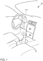
- Fig. 1 shows the typical cockpit of a vehicle 10.
- a passenger car is shown.
- any other vehicle could also be considered as vehicle 10.
- Examples of further vehicles are: buses, commercial vehicles, in particular trucks, agricultural machinery, construction machinery, rail vehicles, etc.
- the use of the invention would generally be possible for land vehicles, rail vehicles, watercraft and aircraft.
- the essential component for the invention in the vehicle 10 is the steering system, of which the steering wheel 12 with parts of the steering column can be seen in the cockpit.
- Fig. 1 a display unit of an infotainment system highlighted with reference numerals. It is a touch-sensitive screen 20, which is attached in the center console.
- the touch-sensitive screen 20 serves in particular to operate functions of the vehicle 10.
- a radio for example, a radio, a navigation system, a playback of stored music pieces and / or an air conditioning system, other electronic devices or other comfort functions or applications of the vehicle 10 can be controlled.
- an "infotainment system" is often spoken of.
- an infotainment system denotes the combination of a car radio, navigation system, hands-free system, driver assistance systems and other functions in a central control unit.
- infotainment is a key word, composed of the words information and entertainment.
- touch-sensitive screen 20 (“touchscreen”) is used to operate the infotainment system, wherein this screen 20 can be viewed and operated particularly well by a driver of the vehicle 10, but also by a passenger of the vehicle 10.
- Mechanical control elements for example keys, rotary controls or combinations thereof, such as push rotary controls, can also be arranged below the screen 20 in an input unit 50.
- steering wheel operation of parts of the infotainment system is also possible.
- the vehicles are equipped with a so-called multifunction steering wheel control. This unit is not shown separately, but is considered part of the input unit 50.
- FIG. 2 A general view of the steering system shows Fig. 2 ,
- the essential components are the steering wheel 12, the steering column 14, the torque sensor 15, the electric motor 16, the rack 18 and the steering aid control unit 186.
- Fig. 3 shows schematically a block diagram of the automotive electronics and an example of some subsystems or applications of the infotainment system.
- the infotainment system comprises: the touch-sensitive display unit 20, a computing device 40, an input unit 50 and a memory 60.
- the display unit 20 comprises both a display area for displaying changeable graphic information and a user interface (touch-sensitive layer) arranged above the display area for the input of Commanded by a user.
- the display unit 20 is connected to the computing device 40 via a data line 70.
- the data line can be designed according to the LVDS standard, corresponding to low voltage differential signaling.
- the display unit 20 receives control data for controlling the display area of the touch screen 20 from the computing device 40.
- Control data of the input commands are also transmitted from the touch screen 20 to the computing device 40 via the data line 70.
- Reference number 50 denotes the input unit. It includes the control elements already mentioned, such as buttons, rotary controls, sliders or rotary pushbuttons, with the help of which the operator can make entries via the menu navigation.
- Input is generally understood to mean the selection of a selected menu option, such as changing a parameter, switching a function on and off, etc.
- the storage device 60 is connected to the computing device 40 via a data line 80.
- a pictogram directory and / or symbol directory with the pictograms and / or symbols for possible superimposition of additional information is stored in the memory 60.
- the other parts of the infotainment system camera 150, radio 140, navigation device 130, telephone 120 and combination instrument 110 are connected via the data bus 100 to the device for operating the infotainment system.
- the data bus 100 is the high-speed version of the CAN bus according to ISO Standard 11898-2. Alternatively, e.g. the use of a bus system based on Ethernet technology such as IEEE 802.03cg is also possible. Bus systems in which data is transmitted via fiber optic cables can also be used. Examples include the MOST bus (Media Oriented System Transport) or the D2B bus (Domestic Digital Bus).
- the vehicle 10 is equipped with a communication module 160 for wireless communication internally and externally. This module is often referred to as an on-board unit.
- It can be used for cellular communication e.g. according to LTE standard, corresponding to Long Term Evolution. It can also be designed for WLAN communication, corresponding to wireless LAN, be it for communication with devices of the occupants in the vehicle or for vehicle-to-vehicle communication etc.
- the communication bus 100 of the infotainment system is connected to a gateway 30.
- the other parts of automotive electronics are also connected to it.
- the communication bus 104 of the drive train which is typically implemented in the form of the CAN bus.
- the control units of the drive train engine control unit 172, ESP control unit 174 and transmission control unit 176 are mentioned and shown as examples.
- the Communication bus 102 for driver assistance systems which can be designed in the form of the FlexRay bus. Three driver assistance systems are shown: a driver assistance system 182 for automatic ACC distance control in accordance with adaptive cruise control, a driver assistance system DCC for adaptive chassis control 184 in accordance with dynamic chassis control and a steering assistance system 186.
- a communication bus 106 is also connected to gateway 30. This connects the gateway 30 to an on-board diagnostic interface 190.
- the task of the gateway 30 is to make the format conversions for the various communication systems 100, 102, 104, 106 so that data can be exchanged with one another.
- the steering assist control unit 186 is discussed in more detail below.
- the hardware structure is in Fig. 4 shown. As already mentioned, it has a redundant structure for security reasons.
- the steering process is controlled by two parallel strands, which are designated channel 1 and channel 2.
- the parts input electronics 220, 320, logic part 240, 340 and power part 270, 370 are each duplicated.
- the multi-phase electric motor 410 which is controlled by the power steering control unit 186. In this case, the electric motor 410 is activated by both lines for full steering assistance. If an error occurs in one of the two lines, the control is prevented by this line for safety reasons.
- the driver no longer receives full steering assistance, but the steering function is still ensured by controlling the other line to the extent that the vehicle 10 can still be safely steered to the roadside or into an emergency stop or into a parking lot.
- the system is designed so that the driver does not have to intervene.
- the steering system can still perform the steering process automatically. After this emergency stop, it is possible to continue driving with manual control of the steering.
- An implementation could also be designed in such a way that both control lines can individually provide full steering support. This would also make it possible for the vehicle to automatically end the journey to "ignition off" with the remaining functional strand after a fault has occurred in one strand. For safety reasons, repeated activation of the automatic driving function would then be blocked.
- a filter unit 228 and 328 in which, for example, the chokes and filters are arranged in order to compensate for disturbances in the supply voltage.
- the supply voltage is present at the current connection 222.
- Contact 224 is used to connect to the torque sensor 15 of the steering system. In the future it may also be the case that both strands will have their own torque sensors. This is attached to the steering column 14 and is read directly. Such a sensor could be dispensed with in the future. Steer-by-wire steering systems are being developed that work without a mechanical steering column.
- the torque sensor 15 then sends the information to the power steering control unit 186 which forces act on the steering.
- the torque sensor 15 typically records the required data of the angle of rotation, direction of rotation and torque electronically. This is important in order to be able to determine the force that the electric motor 410 must exert in order to be able to support the steering process.
- This input signal from the torque sensor 15 is passed on internally to both microcontrollers 250 and 350.
- each microcontroller 250, 350 is separately connected to the communication bus 102.
- the steering aid control unit 186 therefore has two bus connections 226 and 326 for the vehicle bus. In this way, the steering function is guaranteed even if there is a defect in one of the bus connections or the supply lines.
- the logic parts 240 and 340 of the power steering control unit 186 essentially each contain one of the two microcontrollers 250 and 350.
- the microcontroller 250 contains the two computing cores 252 and 254.
- the microcontroller 350 contains the two computing cores 352 and 354.
- the computing cores one Microcontrollers are connected to each other so that they can exchange data, especially computing results.
- a parallel bus is typically used for this.
- Data can also be exchanged between all four computing cores 252, 254, 352, 354 of microcontrollers 250, 350.
- the communication bus 259 between the two microcontrollers 250, 350 is designed as an Ethernet bus. In another embodiment, it can also be designed as a FlexRay or CAN FD communication bus.
- the possibility of data exchange is also required in the security concept, according to which the microcontrollers can check each other and switch off each other when an error is detected.
- the functionality of the mutual checking of the microcontrollers is, however, the subject of another patent application, so that this function is not discussed in more detail here.
- each processor core has two communication ports, for example Ethernet ports, which it can use with the two processor cores of the other microcontroller connected is.
- the computing cores 252 and 352 are equipped with so-called lockstep computing cores 253 and 353. These correspond to parallel computers that run the exact same program. The parallel connection does not serve to increase performance, but for control. A comparison of the results of the individual computing cores takes place, which takes place in individual, timely and non-interruptible steps. The redundancy achieved in this way enables hardware failures in one of the computing cores to be detected and reacted to, as is the case with a dual core in lockstep mode.
- the power section of the power steering control unit 186 is also constructed in parallel.
- the control signal for controlling the electric motor 410 is output by the respective microcontroller 250, 350 in the form of PWM signals, corresponding to "pulse width modulation". These are implemented in the power section 270 and 370 in corresponding converter circuits 272, 274 and 372, 374.
- the electric motor is shown as a 6-phase motor. Depending on which phases are controlled, more or less force is transmitted to the rack. When all phases are activated, the greatest force is applied.
- a converter circuit 272 or 372 is provided for each microcontroller 250, 350.
- gate drive units GDU which convert the PWM signal into corresponding signals for controlling an amplifier (power MOSFET or IGBT module).
- GDU gate drive units
- the control signals Before the control signals reach the electric motor 410, they still pass a phase isolating circuit 274 or 374.
- the actuation of the electric motor 410 can be switched off in the corresponding path via the phase isolating circuits.
- the control In accordance with the connections drawn between microcontrollers and phase separation circuits, the control can only be switched off by the microcontroller of the respective control train.
- a rotor position sensor 276, 376 is also provided for each strand. This detects the movement of the rotor of the electric motor 410.
- the safety concept requires that the power steering control unit 186 be constructed redundantly. There are therefore two control lines, each of which can maintain the control function.
- the correct functioning of the two microcontrollers 250, 350 is checked by a logic decision module 261, 262, 361, 362, which is distributed over the various computing cores of the microcontrollers 250, 350.
- the correct function of the rotor position sensors 276, 376 must also be checked according to the safety concept. How this is done according to the new proposal will be discussed in more detail below.
- the Fig. 5 shows the essential components and modules that are used for this.
- the same reference numbers designate the same components as in Fig. 4 ,
- the logic parts 240, 340 and power parts 270, 370 of the two control lines of the power steering control unit 186 are shown. No changes are required in the input electrical parts 220, 320, so these parts are not specifically shown.
- the logic components 240, 340 show the two microcontrollers 250 and 350. Microcontrollers 250 and 350 can be the same as in FIG Fig. 4 shown.
- the difference is in Fig. 5 a software module is shown for each of the microcontrollers 250, 350.
- These software modules correspond to status monitors 257, 357, which have the purpose of monitoring the correct functioning of the rotor position sensors 276, 376. This is done as follows:
- the condition observers 257, 357 each contain a software module for determining the ideal rotor behavior 251, 351.
- This module calculates the required movement of the rotor depending on the input variables of the torque sensor 15 or other information such as the steering command, which was calculated by a driver assistance system and was transmitted to the power steering control unit 186 via the communication bus 102 and the speed of the vehicle that was transmitted from the instrument cluster 110 to the power steering control unit 186.
- the ideal change in the rotor in the electric motor 410 is determined from the target specification in the form of the steering command.
- the ideal change is e.g. from the rotor angle to be set and the rotor speed to be set or the rotor acceleration to be set.
- the exact type of calculation does not play a decisive role in the further explanation of the proposal.
- the respective status observer also contains a further software module 256, 356.
- This is used to determine the real rotor behavior.
- these software modules evaluate the data of the respective rotor position sensor 276, 376 and a component for phase feedback 278, 378.
- the measurement data phase current and phase voltage are recorded in this component for phase feedback.
- the use of this information makes the detection of the real rotor movement more precise.
- the real rotor behavior could also be determined without phase feedback.
- the current rotor position ie the current angle of the rotor in the installed electric motor 410, is detected via the rotor position sensor 276, 376.
- the component is phase separator in the Fig. 5 is no longer shown separately, but it is pointed out that this function is also integrated in the phase feedback component 278, 378.
- a decision module 258, 358 is provided in the status observer 257 and 357.
- the ideal rotor behavior determined by the other modules of the status observer and the real rotor behavior are compared with one another.
- the real rotor behavior which was determined by the other microcontroller, is also compared.
- the data with the determined rotor behavior are exchanged among the microcontrollers 250, 350.
- Three statements are then available, from which a majority decision can be made. Two independent actual sizes and one model size. These three pieces of information then form the basis for a majority decision.
- a majority decision is made in the respective decision module 258, 358 with the data of the ideal rotor behavior and the data of the two determined real rotor behavior. If it emerges that there is a deviation in one of the real rotor behaviors, the corresponding strand in which the rotor position sensor 276, 376 identified as defective is located is switched off. For this purpose, there is a connection between microcontroller 250, 350 and the corresponding component phase readback 278, 378, which is also responsible for phase separation.
- the proposed method and associated devices can be implemented in various forms of hardware, software, firmware, special processors, or a combination thereof.
- Special processors can include application-specific integrated circuits (ASICs), reduced instruction set computers (RISC) and / or field programmable gate arrays (FPGAs).
- ASICs application-specific integrated circuits
- RISC reduced instruction set computers
- FPGAs field programmable gate arrays
- the proposed method and the device are preferably implemented as a combination of hardware and software.
- the software is preferably run as an application program on a program storage device Installed. Typically, it is a machine based on a computer platform that has hardware such as one or more central processing units (CPU), a random access memory (RAM) and one or more input / output (I / O) interface (s).
- An operating system is typically also installed on the computer platform.
- the various processes and functions described here can be part of the application program or part of the operating system.
- control commands are not transmitted to the control device from the outside, but are generated in the control device itself.
Landscapes
- Engineering & Computer Science (AREA)
- Mechanical Engineering (AREA)
- Automation & Control Theory (AREA)
- Transportation (AREA)
- Chemical & Material Sciences (AREA)
- Combustion & Propulsion (AREA)
- Human Computer Interaction (AREA)
- Physics & Mathematics (AREA)
- General Physics & Mathematics (AREA)
- Steering Control In Accordance With Driving Conditions (AREA)
- Power Steering Mechanism (AREA)
- Control Of Driving Devices And Active Controlling Of Vehicle (AREA)
Applications Claiming Priority (1)
| Application Number | Priority Date | Filing Date | Title |
|---|---|---|---|
| DE102018209833.6A DE102018209833B4 (de) | 2018-06-19 | 2018-06-19 | Verfahren und Vorrichtung für die Steuerung eines sicherheitsrelevanten Vorganges, sowie Fahrzeug |
Publications (2)
| Publication Number | Publication Date |
|---|---|
| EP3584140A1 true EP3584140A1 (fr) | 2019-12-25 |
| EP3584140B1 EP3584140B1 (fr) | 2022-07-20 |
Family
ID=66793761
Family Applications (1)
| Application Number | Title | Priority Date | Filing Date |
|---|---|---|---|
| EP19176904.1A Active EP3584140B1 (fr) | 2018-06-19 | 2019-05-28 | Procédé et dispositif de commande d'un processus de sécurité ainsi que véhicule |
Country Status (5)
| Country | Link |
|---|---|
| US (1) | US11220288B2 (fr) |
| EP (1) | EP3584140B1 (fr) |
| JP (1) | JP2019218045A (fr) |
| CN (1) | CN110615004A (fr) |
| DE (1) | DE102018209833B4 (fr) |
Cited By (1)
| Publication number | Priority date | Publication date | Assignee | Title |
|---|---|---|---|---|
| WO2021078660A1 (fr) * | 2019-10-23 | 2021-04-29 | Thyssenkrupp Presta Ag | Dispositif d'évaluation conçu pour réaliser une évaluation tolérante aux erreurs de signaux de détection pour un appareil de commande de moteur d'une direction de véhicule automobile et direction de véhicule automobile |
Families Citing this family (13)
| Publication number | Priority date | Publication date | Assignee | Title |
|---|---|---|---|---|
| JP2020503612A (ja) * | 2016-12-22 | 2020-01-30 | ニッサン ノース アメリカ,インク | 自律走行車両サービスシステム |
| EP3720098B1 (fr) | 2019-04-02 | 2023-10-11 | The Raymond Corporation | Systèmes et méthodes permettant à un contrôleur d'arbitrage d'arbitrer de multiples demandes d'automatisation sur un véhicule de manutention de matériaux d'entrepôt |
| IT201900018362A1 (it) * | 2019-10-10 | 2021-04-10 | Texa Spa | Metodo e sistema di controllo di almeno due motori elettrici di trazione di un veicolo |
| DE102020203419A1 (de) * | 2020-01-15 | 2021-07-15 | Volkswagen Aktiengesellschaft | Verfahren und Vorrichtung zum Betreiben eines automatisiert fahrenden Fahrzeugs |
| KR20210101857A (ko) * | 2020-02-11 | 2021-08-19 | 주식회사 만도 | 조향 어시스트 장치 및 방법과, 조향 시스템 |
| CN111497762B (zh) * | 2020-04-09 | 2021-08-06 | 东风汽车集团有限公司 | 一种用于汽车电子控制器的双cpu控制系统及控制方法 |
| US20210331740A1 (en) * | 2020-04-22 | 2021-10-28 | Steering Solutions Ip Holding Corporation | Systems and method for electronic power steering redundant bus communication |
| CN111762179B (zh) * | 2020-05-11 | 2022-07-12 | 广州文远知行科技有限公司 | 车辆控制方法、装置、车辆和计算机可读存储介质 |
| KR20220008011A (ko) * | 2020-07-13 | 2022-01-20 | 현대모비스 주식회사 | 전동식 조향 시스템에서 아날로그 디지털 컨버터의 레퍼런스 신호의 오류를 검출하는 방법 및 그 전자 장치 |
| US11738799B2 (en) * | 2020-10-12 | 2023-08-29 | Ford Global Technologies, Llc | Steering system with multiple controllers |
| DE102020134176A1 (de) | 2020-12-18 | 2022-06-23 | Horsch Maschinen Gmbh | Kommunikationssystem für eine landwirtschaftliche maschine und verfahren zur herstellung einer landwirtschaftlichen maschine |
| DE102021206379A1 (de) | 2021-06-22 | 2022-12-22 | Continental Autonomous Mobility Germany GmbH | Steuereinrichtung sowie Assistenzsystem für ein Fahrzeug |
| CN116135668B (zh) * | 2023-03-29 | 2024-05-14 | 重庆长安汽车股份有限公司 | 一种车辆转向冗余控制方法、装置、设备及介质 |
Citations (8)
| Publication number | Priority date | Publication date | Assignee | Title |
|---|---|---|---|---|
| DE19946073A1 (de) * | 1999-09-25 | 2001-05-10 | Volkswagen Ag | System zur Steuerung von Fahrzeugkomponenten nach dem "Drive By Wire"-Prinzip |
| DE10052343A1 (de) * | 2000-10-21 | 2002-07-11 | Bosch Gmbh Robert | Verfahren zum Steuern eines Steerby-Wire-Lenksystems |
| EP1426266A2 (fr) * | 2002-12-02 | 2004-06-09 | Toyoda Koki Kabushiki Kaisha | Dispositif de commande de direction de véhicule |
| EP2450261A2 (fr) | 2010-11-09 | 2012-05-09 | Audi AG | Dispositif de commande d'un moteur électrique pour une direction assistée |
| DE102016203090A1 (de) | 2016-02-26 | 2017-08-31 | Robert Bosch Gmbh | Steuergerät, insbesondere für ein Kraftfahrzeug, mit über Ethernet verbundenen Mikrocontrollern |
| WO2017159090A1 (fr) * | 2016-03-17 | 2017-09-21 | 株式会社デンソー | Dispositif de capteur, et dispositif de direction à assistance électrique le comprenant |
| DE102016205109A1 (de) | 2016-03-29 | 2017-10-05 | Robert Bosch Gmbh | Mikroprozessor, insbesondere für ein Kraftfahrzeug |
| EP3299257A1 (fr) * | 2016-09-23 | 2018-03-28 | Jtekt Corporation | Organe de commande de moteur et dispositif de direction |
Family Cites Families (18)
| Publication number | Priority date | Publication date | Assignee | Title |
|---|---|---|---|---|
| US6687637B2 (en) * | 2001-06-18 | 2004-02-03 | Globvision Inc. | Data sensor validation system and method |
| US6683432B2 (en) * | 2001-09-12 | 2004-01-27 | Eigenpoint Company | Safety circuit with automatic recovery |
| US7392122B2 (en) * | 2002-06-13 | 2008-06-24 | Oshkosh Truck Corporation | Steering control system and method |
| JP2006228002A (ja) * | 2005-02-18 | 2006-08-31 | Japan Aviation Electronics Industry Ltd | 故障検知機能付き二重系システム |
| DE102009005836A1 (de) | 2009-01-21 | 2010-07-22 | Volkswagen Ag | Lenkeinrichtung für Kraftfahrzeuge und Verfahren zum Betreiben einer Lenkeinrichtung |
| DE112010006048B4 (de) * | 2010-12-01 | 2022-03-31 | Toyota Jidosha Kabushiki Kaisha | Fahrzeugbewegungssteuervorrichtung |
| DE102011003693A1 (de) * | 2011-02-07 | 2012-08-09 | Robert Bosch Gmbh | Vorrichtung zum Kompensieren eines Störgiermoments bei einem Fahrzeug mit mindestens zwei radindividuellen Antrieben |
| US8606447B2 (en) * | 2011-05-23 | 2013-12-10 | GM Global Technology Operations LLC | Method and apparatus to operate a powertrain system including an electric machine having a disconnected high-voltage battery |
| RU2623792C2 (ru) * | 2012-02-10 | 2017-06-29 | Мерлин Технолоджи, Инк. | Система и способы управления с помощью автопилота |
| FR2987017B1 (fr) * | 2012-02-21 | 2014-10-03 | Renault Sa | Procede et dispositif de sauvegarde du fonctionnement d'un vehicule |
| DE102013203978A1 (de) | 2013-03-08 | 2014-09-11 | Bayerische Motoren Werke Aktiengesellschaft | Fahrzeug-Lenksystem |
| KR101551038B1 (ko) * | 2013-12-31 | 2015-09-18 | 현대자동차주식회사 | 전동식 파워스티어링 시스템의 제어 방법 및 장치 |
| CN106164814A (zh) * | 2015-03-13 | 2016-11-23 | (株)未来百乐 | 用于由移动设备控制传感器的移动设备和方法 |
| DE102015121910A1 (de) | 2015-12-16 | 2017-06-22 | Robert Bosch Automotive Steering Gmbh | Verfahren zur Plausibilisierung von Sensorsignalen, insbesondere in Lenksystemen |
| WO2017122329A1 (fr) * | 2016-01-14 | 2017-07-20 | 三菱電機株式会社 | Dispositif de direction assistée électrique |
| US10818105B1 (en) * | 2016-01-22 | 2020-10-27 | State Farm Mutual Automobile Insurance Company | Sensor malfunction detection |
| WO2018051550A1 (fr) * | 2016-09-15 | 2018-03-22 | 日立オートモティブシステムズ株式会社 | Actionneur de dispositif monté sur véhicule et dispositif de direction assistée |
| WO2018122329A1 (fr) | 2016-12-28 | 2018-07-05 | Albert-Ludwigs-Universität Freiburg | Agencement de circuit convertisseur ca/cc et procédé de fonctionnement d'un agencement de circuit convertisseur ca/cc respectif |
-
2018
- 2018-06-19 DE DE102018209833.6A patent/DE102018209833B4/de active Active
-
2019
- 2019-03-12 CN CN201910184314.4A patent/CN110615004A/zh active Pending
- 2019-03-26 JP JP2019058411A patent/JP2019218045A/ja active Pending
- 2019-05-28 EP EP19176904.1A patent/EP3584140B1/fr active Active
- 2019-06-13 US US16/439,784 patent/US11220288B2/en active Active
Patent Citations (8)
| Publication number | Priority date | Publication date | Assignee | Title |
|---|---|---|---|---|
| DE19946073A1 (de) * | 1999-09-25 | 2001-05-10 | Volkswagen Ag | System zur Steuerung von Fahrzeugkomponenten nach dem "Drive By Wire"-Prinzip |
| DE10052343A1 (de) * | 2000-10-21 | 2002-07-11 | Bosch Gmbh Robert | Verfahren zum Steuern eines Steerby-Wire-Lenksystems |
| EP1426266A2 (fr) * | 2002-12-02 | 2004-06-09 | Toyoda Koki Kabushiki Kaisha | Dispositif de commande de direction de véhicule |
| EP2450261A2 (fr) | 2010-11-09 | 2012-05-09 | Audi AG | Dispositif de commande d'un moteur électrique pour une direction assistée |
| DE102016203090A1 (de) | 2016-02-26 | 2017-08-31 | Robert Bosch Gmbh | Steuergerät, insbesondere für ein Kraftfahrzeug, mit über Ethernet verbundenen Mikrocontrollern |
| WO2017159090A1 (fr) * | 2016-03-17 | 2017-09-21 | 株式会社デンソー | Dispositif de capteur, et dispositif de direction à assistance électrique le comprenant |
| DE102016205109A1 (de) | 2016-03-29 | 2017-10-05 | Robert Bosch Gmbh | Mikroprozessor, insbesondere für ein Kraftfahrzeug |
| EP3299257A1 (fr) * | 2016-09-23 | 2018-03-28 | Jtekt Corporation | Organe de commande de moteur et dispositif de direction |
Cited By (1)
| Publication number | Priority date | Publication date | Assignee | Title |
|---|---|---|---|---|
| WO2021078660A1 (fr) * | 2019-10-23 | 2021-04-29 | Thyssenkrupp Presta Ag | Dispositif d'évaluation conçu pour réaliser une évaluation tolérante aux erreurs de signaux de détection pour un appareil de commande de moteur d'une direction de véhicule automobile et direction de véhicule automobile |
Also Published As
| Publication number | Publication date |
|---|---|
| EP3584140B1 (fr) | 2022-07-20 |
| US20190382045A1 (en) | 2019-12-19 |
| JP2019218045A (ja) | 2019-12-26 |
| DE102018209833B4 (de) | 2022-03-24 |
| CN110615004A (zh) | 2019-12-27 |
| US11220288B2 (en) | 2022-01-11 |
| DE102018209833A1 (de) | 2019-12-19 |
Similar Documents
| Publication | Publication Date | Title |
|---|---|---|
| EP3584140B1 (fr) | Procédé et dispositif de commande d'un processus de sécurité ainsi que véhicule | |
| EP2176106B1 (fr) | Système de freinage pour véhicule et procédé d'exploitation d'un système de freinage pour véhicule | |
| DE4039005C2 (de) | Steuereinrichtung für ein Fahrzeug | |
| EP2786225B1 (fr) | Procédé pour faire fonctionner au moins deux unités de traitement de données de grande disponibilité, notamment dans un véhicule, et dispositif pour faire fonctionner une machine | |
| DE102020116410A1 (de) | Vorrichtung zur Steuerung einer Bremse eines autonomen Fahrzeugs | |
| DE102013020177A1 (de) | Kraftfahrzeug | |
| DE102017217856A1 (de) | Bremssystem für ein Kraftfahrzeug und Verfahren zum Betreiben eines Bremssystems | |
| EP3385934B1 (fr) | Dispositif de commande d'un processus relatif à la sécurité, procédé d'essai de la capacité de fonctionnement dudit dispositif ainsi que véhicule doté dudit dispositif | |
| WO2014180551A1 (fr) | Procédé pour faire fonctionner un système de freinage, en conduite entièrement automatique, et véhicule correspondant | |
| EP1379420A2 (fr) | Systeme de commande electronique, destine en particulier a un systeme de freinage de vehicule | |
| EP3741635B1 (fr) | Système de commande de frein | |
| EP3473512B1 (fr) | Module fonctionnel, unité de commande pour un système d'aide au fonctionnement et dispositif de travail | |
| WO2007036472A1 (fr) | Systeme de communication pour un appareil technique, en particulier pour un vehicule a moteur | |
| DE102018220605A1 (de) | Kraftfahrzeugnetzwerk und Verfahren zum Betreiben eines Kraftfahrzeugnetzwerks | |
| DE10142511A1 (de) | Fehlerbehandlung von Softwaremodulen | |
| DE102013200528A1 (de) | Verfahren und Vorrichtung zum Betrieb eines Kommunikationsnetzwerks insbesondere eines Kraftfahrzeugs | |
| EP3511226A1 (fr) | Système d'entraînement électrique et procédé de fonctionnement d'un système d'entraînement électrique | |
| DE102018207542B4 (de) | Verfahren und Vorrichtung für eine Steuerung eines sicherheitsrelevanten Vorganges, sowie Fahrzeug | |
| WO2018050648A1 (fr) | Système de transmission d'énergie et/ou de données | |
| DE102019132428A1 (de) | Funktionsorientierte Elektronik-Architektur | |
| DE10359875A1 (de) | Digitales Netzwerk für Kraftfahrzeuge | |
| DE102022213783B4 (de) | Verfahren zur Plausibilisierung eines Parameters | |
| DE102021206184A1 (de) | Mechatronische Systemarchitektur zur Fusion der Lenkungs- und Bremssysteme eines Fahrzeugs | |
| AT525924A1 (de) | Verteiltes Steuerungs- und Sicherheitssystem für ein Kraftfahrzeug mit wenigstens einem Inverter und ein entsprechendes Verfahren | |
| DE102020209658A1 (de) | Bremseinrichtung für ein Fahrzeug und Verfahren zum Betreiben einer Bremseinrichtung |
Legal Events
| Date | Code | Title | Description |
|---|---|---|---|
| PUAI | Public reference made under article 153(3) epc to a published international application that has entered the european phase |
Free format text: ORIGINAL CODE: 0009012 |
|
| STAA | Information on the status of an ep patent application or granted ep patent |
Free format text: STATUS: THE APPLICATION HAS BEEN PUBLISHED |
|
| AK | Designated contracting states |
Kind code of ref document: A1 Designated state(s): AL AT BE BG CH CY CZ DE DK EE ES FI FR GB GR HR HU IE IS IT LI LT LU LV MC MK MT NL NO PL PT RO RS SE SI SK SM TR |
|
| AX | Request for extension of the european patent |
Extension state: BA ME |
|
| STAA | Information on the status of an ep patent application or granted ep patent |
Free format text: STATUS: REQUEST FOR EXAMINATION WAS MADE |
|
| 17P | Request for examination filed |
Effective date: 20200625 |
|
| RBV | Designated contracting states (corrected) |
Designated state(s): AL AT BE BG CH CY CZ DE DK EE ES FI FR GB GR HR HU IE IS IT LI LT LU LV MC MK MT NL NO PL PT RO RS SE SI SK SM TR |
|
| STAA | Information on the status of an ep patent application or granted ep patent |
Free format text: STATUS: EXAMINATION IS IN PROGRESS |
|
| STAA | Information on the status of an ep patent application or granted ep patent |
Free format text: STATUS: EXAMINATION IS IN PROGRESS |
|
| 17Q | First examination report despatched |
Effective date: 20201102 |
|
| GRAP | Despatch of communication of intention to grant a patent |
Free format text: ORIGINAL CODE: EPIDOSNIGR1 |
|
| STAA | Information on the status of an ep patent application or granted ep patent |
Free format text: STATUS: GRANT OF PATENT IS INTENDED |
|
| INTG | Intention to grant announced |
Effective date: 20220502 |
|
| GRAS | Grant fee paid |
Free format text: ORIGINAL CODE: EPIDOSNIGR3 |
|
| GRAA | (expected) grant |
Free format text: ORIGINAL CODE: 0009210 |
|
| STAA | Information on the status of an ep patent application or granted ep patent |
Free format text: STATUS: THE PATENT HAS BEEN GRANTED |
|
| AK | Designated contracting states |
Kind code of ref document: B1 Designated state(s): AL AT BE BG CH CY CZ DE DK EE ES FI FR GB GR HR HU IE IS IT LI LT LU LV MC MK MT NL NO PL PT RO RS SE SI SK SM TR |
|
| REG | Reference to a national code |
Ref country code: CH Ref legal event code: EP |
|
| REG | Reference to a national code |
Ref country code: DE Ref legal event code: R096 Ref document number: 502019004991 Country of ref document: DE |
|
| REG | Reference to a national code |
Ref country code: AT Ref legal event code: REF Ref document number: 1505372 Country of ref document: AT Kind code of ref document: T Effective date: 20220815 |
|
| REG | Reference to a national code |
Ref country code: IE Ref legal event code: FG4D Free format text: LANGUAGE OF EP DOCUMENT: GERMAN |
|
| REG | Reference to a national code |
Ref country code: LT Ref legal event code: MG9D |
|
| REG | Reference to a national code |
Ref country code: NL Ref legal event code: MP Effective date: 20220720 |
|
| PG25 | Lapsed in a contracting state [announced via postgrant information from national office to epo] |
Ref country code: SE Free format text: LAPSE BECAUSE OF FAILURE TO SUBMIT A TRANSLATION OF THE DESCRIPTION OR TO PAY THE FEE WITHIN THE PRESCRIBED TIME-LIMIT Effective date: 20220720 Ref country code: RS Free format text: LAPSE BECAUSE OF FAILURE TO SUBMIT A TRANSLATION OF THE DESCRIPTION OR TO PAY THE FEE WITHIN THE PRESCRIBED TIME-LIMIT Effective date: 20220720 Ref country code: PT Free format text: LAPSE BECAUSE OF FAILURE TO SUBMIT A TRANSLATION OF THE DESCRIPTION OR TO PAY THE FEE WITHIN THE PRESCRIBED TIME-LIMIT Effective date: 20221121 Ref country code: NO Free format text: LAPSE BECAUSE OF FAILURE TO SUBMIT A TRANSLATION OF THE DESCRIPTION OR TO PAY THE FEE WITHIN THE PRESCRIBED TIME-LIMIT Effective date: 20221020 Ref country code: NL Free format text: LAPSE BECAUSE OF FAILURE TO SUBMIT A TRANSLATION OF THE DESCRIPTION OR TO PAY THE FEE WITHIN THE PRESCRIBED TIME-LIMIT Effective date: 20220720 Ref country code: LV Free format text: LAPSE BECAUSE OF FAILURE TO SUBMIT A TRANSLATION OF THE DESCRIPTION OR TO PAY THE FEE WITHIN THE PRESCRIBED TIME-LIMIT Effective date: 20220720 Ref country code: LT Free format text: LAPSE BECAUSE OF FAILURE TO SUBMIT A TRANSLATION OF THE DESCRIPTION OR TO PAY THE FEE WITHIN THE PRESCRIBED TIME-LIMIT Effective date: 20220720 Ref country code: FI Free format text: LAPSE BECAUSE OF FAILURE TO SUBMIT A TRANSLATION OF THE DESCRIPTION OR TO PAY THE FEE WITHIN THE PRESCRIBED TIME-LIMIT Effective date: 20220720 Ref country code: ES Free format text: LAPSE BECAUSE OF FAILURE TO SUBMIT A TRANSLATION OF THE DESCRIPTION OR TO PAY THE FEE WITHIN THE PRESCRIBED TIME-LIMIT Effective date: 20220720 |
|
| PG25 | Lapsed in a contracting state [announced via postgrant information from national office to epo] |
Ref country code: PL Free format text: LAPSE BECAUSE OF FAILURE TO SUBMIT A TRANSLATION OF THE DESCRIPTION OR TO PAY THE FEE WITHIN THE PRESCRIBED TIME-LIMIT Effective date: 20220720 Ref country code: IS Free format text: LAPSE BECAUSE OF FAILURE TO SUBMIT A TRANSLATION OF THE DESCRIPTION OR TO PAY THE FEE WITHIN THE PRESCRIBED TIME-LIMIT Effective date: 20221120 Ref country code: HR Free format text: LAPSE BECAUSE OF FAILURE TO SUBMIT A TRANSLATION OF THE DESCRIPTION OR TO PAY THE FEE WITHIN THE PRESCRIBED TIME-LIMIT Effective date: 20220720 Ref country code: GR Free format text: LAPSE BECAUSE OF FAILURE TO SUBMIT A TRANSLATION OF THE DESCRIPTION OR TO PAY THE FEE WITHIN THE PRESCRIBED TIME-LIMIT Effective date: 20221021 |
|
| REG | Reference to a national code |
Ref country code: DE Ref legal event code: R097 Ref document number: 502019004991 Country of ref document: DE |
|
| PG25 | Lapsed in a contracting state [announced via postgrant information from national office to epo] |
Ref country code: SM Free format text: LAPSE BECAUSE OF FAILURE TO SUBMIT A TRANSLATION OF THE DESCRIPTION OR TO PAY THE FEE WITHIN THE PRESCRIBED TIME-LIMIT Effective date: 20220720 Ref country code: RO Free format text: LAPSE BECAUSE OF FAILURE TO SUBMIT A TRANSLATION OF THE DESCRIPTION OR TO PAY THE FEE WITHIN THE PRESCRIBED TIME-LIMIT Effective date: 20220720 Ref country code: DK Free format text: LAPSE BECAUSE OF FAILURE TO SUBMIT A TRANSLATION OF THE DESCRIPTION OR TO PAY THE FEE WITHIN THE PRESCRIBED TIME-LIMIT Effective date: 20220720 Ref country code: CZ Free format text: LAPSE BECAUSE OF FAILURE TO SUBMIT A TRANSLATION OF THE DESCRIPTION OR TO PAY THE FEE WITHIN THE PRESCRIBED TIME-LIMIT Effective date: 20220720 |
|
| PLBE | No opposition filed within time limit |
Free format text: ORIGINAL CODE: 0009261 |
|
| STAA | Information on the status of an ep patent application or granted ep patent |
Free format text: STATUS: NO OPPOSITION FILED WITHIN TIME LIMIT |
|
| PG25 | Lapsed in a contracting state [announced via postgrant information from national office to epo] |
Ref country code: SK Free format text: LAPSE BECAUSE OF FAILURE TO SUBMIT A TRANSLATION OF THE DESCRIPTION OR TO PAY THE FEE WITHIN THE PRESCRIBED TIME-LIMIT Effective date: 20220720 Ref country code: EE Free format text: LAPSE BECAUSE OF FAILURE TO SUBMIT A TRANSLATION OF THE DESCRIPTION OR TO PAY THE FEE WITHIN THE PRESCRIBED TIME-LIMIT Effective date: 20220720 |
|
| 26N | No opposition filed |
Effective date: 20230421 |
|
| P01 | Opt-out of the competence of the unified patent court (upc) registered |
Effective date: 20230523 |
|
| PG25 | Lapsed in a contracting state [announced via postgrant information from national office to epo] |
Ref country code: AL Free format text: LAPSE BECAUSE OF FAILURE TO SUBMIT A TRANSLATION OF THE DESCRIPTION OR TO PAY THE FEE WITHIN THE PRESCRIBED TIME-LIMIT Effective date: 20220720 |
|
| PG25 | Lapsed in a contracting state [announced via postgrant information from national office to epo] |
Ref country code: SI Free format text: LAPSE BECAUSE OF FAILURE TO SUBMIT A TRANSLATION OF THE DESCRIPTION OR TO PAY THE FEE WITHIN THE PRESCRIBED TIME-LIMIT Effective date: 20220720 |
|
| REG | Reference to a national code |
Ref country code: CH Ref legal event code: PL |
|
| PG25 | Lapsed in a contracting state [announced via postgrant information from national office to epo] |
Ref country code: MC Free format text: LAPSE BECAUSE OF FAILURE TO SUBMIT A TRANSLATION OF THE DESCRIPTION OR TO PAY THE FEE WITHIN THE PRESCRIBED TIME-LIMIT Effective date: 20220720 |
|
| REG | Reference to a national code |
Ref country code: BE Ref legal event code: MM Effective date: 20230531 |
|
| PG25 | Lapsed in a contracting state [announced via postgrant information from national office to epo] |
Ref country code: MC Free format text: LAPSE BECAUSE OF FAILURE TO SUBMIT A TRANSLATION OF THE DESCRIPTION OR TO PAY THE FEE WITHIN THE PRESCRIBED TIME-LIMIT Effective date: 20220720 Ref country code: LU Free format text: LAPSE BECAUSE OF NON-PAYMENT OF DUE FEES Effective date: 20230528 Ref country code: LI Free format text: LAPSE BECAUSE OF NON-PAYMENT OF DUE FEES Effective date: 20230531 Ref country code: CH Free format text: LAPSE BECAUSE OF NON-PAYMENT OF DUE FEES Effective date: 20230531 |
|
| REG | Reference to a national code |
Ref country code: IE Ref legal event code: MM4A |
|
| PG25 | Lapsed in a contracting state [announced via postgrant information from national office to epo] |
Ref country code: IE Free format text: LAPSE BECAUSE OF NON-PAYMENT OF DUE FEES Effective date: 20230528 |
|
| PG25 | Lapsed in a contracting state [announced via postgrant information from national office to epo] |
Ref country code: IE Free format text: LAPSE BECAUSE OF NON-PAYMENT OF DUE FEES Effective date: 20230528 |
|
| PG25 | Lapsed in a contracting state [announced via postgrant information from national office to epo] |
Ref country code: IT Free format text: LAPSE BECAUSE OF FAILURE TO SUBMIT A TRANSLATION OF THE DESCRIPTION OR TO PAY THE FEE WITHIN THE PRESCRIBED TIME-LIMIT Effective date: 20220720 Ref country code: BE Free format text: LAPSE BECAUSE OF NON-PAYMENT OF DUE FEES Effective date: 20230531 |
|
| PGFP | Annual fee paid to national office [announced via postgrant information from national office to epo] |
Ref country code: GB Payment date: 20240521 Year of fee payment: 6 |
|
| PGFP | Annual fee paid to national office [announced via postgrant information from national office to epo] |
Ref country code: DE Payment date: 20240531 Year of fee payment: 6 |
|
| PGFP | Annual fee paid to national office [announced via postgrant information from national office to epo] |
Ref country code: FR Payment date: 20240527 Year of fee payment: 6 |