EP3584131A1 - Electric component assembly, and brake fluid pressure control device for vehicle - Google Patents
Electric component assembly, and brake fluid pressure control device for vehicle Download PDFInfo
- Publication number
- EP3584131A1 EP3584131A1 EP18754509.0A EP18754509A EP3584131A1 EP 3584131 A1 EP3584131 A1 EP 3584131A1 EP 18754509 A EP18754509 A EP 18754509A EP 3584131 A1 EP3584131 A1 EP 3584131A1
- Authority
- EP
- European Patent Office
- Prior art keywords
- electric component
- housing
- press
- terminal
- coil assembly
- Prior art date
- Legal status (The legal status is an assumption and is not a legal conclusion. Google has not performed a legal analysis and makes no representation as to the accuracy of the status listed.)
- Granted
Links
- 239000012530 fluid Substances 0.000 title claims description 51
- 238000003780 insertion Methods 0.000 claims abstract description 27
- 230000037431 insertion Effects 0.000 claims abstract description 27
- 238000004804 winding Methods 0.000 claims description 16
- 230000004308 accommodation Effects 0.000 description 34
- 230000002093 peripheral effect Effects 0.000 description 29
- 230000000712 assembly Effects 0.000 description 28
- 238000000429 assembly Methods 0.000 description 28
- 239000000853 adhesive Substances 0.000 description 22
- 230000001070 adhesive effect Effects 0.000 description 22
- 230000012447 hatching Effects 0.000 description 13
- 239000002184 metal Substances 0.000 description 4
- 238000005192 partition Methods 0.000 description 4
- 238000004080 punching Methods 0.000 description 4
- 230000003014 reinforcing effect Effects 0.000 description 4
- 230000000694 effects Effects 0.000 description 3
- 238000003825 pressing Methods 0.000 description 3
- 239000011248 coating agent Substances 0.000 description 2
- 238000000576 coating method Methods 0.000 description 2
- 238000009413 insulation Methods 0.000 description 2
- 239000000463 material Substances 0.000 description 2
- 238000000034 method Methods 0.000 description 2
- 238000000465 moulding Methods 0.000 description 2
- 230000001133 acceleration Effects 0.000 description 1
- 230000001747 exhibiting effect Effects 0.000 description 1
- 238000001746 injection moulding Methods 0.000 description 1
- 239000012212 insulator Substances 0.000 description 1
- 239000007769 metal material Substances 0.000 description 1
- 230000000149 penetrating effect Effects 0.000 description 1
- 239000004065 semiconductor Substances 0.000 description 1
- 239000000243 solution Substances 0.000 description 1
- 238000003466 welding Methods 0.000 description 1
Images


Classifications
-
- B—PERFORMING OPERATIONS; TRANSPORTING
- B60—VEHICLES IN GENERAL
- B60T—VEHICLE BRAKE CONTROL SYSTEMS OR PARTS THEREOF; BRAKE CONTROL SYSTEMS OR PARTS THEREOF, IN GENERAL; ARRANGEMENT OF BRAKING ELEMENTS ON VEHICLES IN GENERAL; PORTABLE DEVICES FOR PREVENTING UNWANTED MOVEMENT OF VEHICLES; VEHICLE MODIFICATIONS TO FACILITATE COOLING OF BRAKES
- B60T8/00—Arrangements for adjusting wheel-braking force to meet varying vehicular or ground-surface conditions, e.g. limiting or varying distribution of braking force
- B60T8/32—Arrangements for adjusting wheel-braking force to meet varying vehicular or ground-surface conditions, e.g. limiting or varying distribution of braking force responsive to a speed condition, e.g. acceleration or deceleration
- B60T8/34—Arrangements for adjusting wheel-braking force to meet varying vehicular or ground-surface conditions, e.g. limiting or varying distribution of braking force responsive to a speed condition, e.g. acceleration or deceleration having a fluid pressure regulator responsive to a speed condition
- B60T8/36—Arrangements for adjusting wheel-braking force to meet varying vehicular or ground-surface conditions, e.g. limiting or varying distribution of braking force responsive to a speed condition, e.g. acceleration or deceleration having a fluid pressure regulator responsive to a speed condition including a pilot valve responding to an electromagnetic force
- B60T8/3615—Electromagnetic valves specially adapted for anti-lock brake and traction control systems
- B60T8/3675—Electromagnetic valves specially adapted for anti-lock brake and traction control systems integrated in modulator units
-
- B—PERFORMING OPERATIONS; TRANSPORTING
- B60—VEHICLES IN GENERAL
- B60T—VEHICLE BRAKE CONTROL SYSTEMS OR PARTS THEREOF; BRAKE CONTROL SYSTEMS OR PARTS THEREOF, IN GENERAL; ARRANGEMENT OF BRAKING ELEMENTS ON VEHICLES IN GENERAL; PORTABLE DEVICES FOR PREVENTING UNWANTED MOVEMENT OF VEHICLES; VEHICLE MODIFICATIONS TO FACILITATE COOLING OF BRAKES
- B60T8/00—Arrangements for adjusting wheel-braking force to meet varying vehicular or ground-surface conditions, e.g. limiting or varying distribution of braking force
- B60T8/32—Arrangements for adjusting wheel-braking force to meet varying vehicular or ground-surface conditions, e.g. limiting or varying distribution of braking force responsive to a speed condition, e.g. acceleration or deceleration
- B60T8/34—Arrangements for adjusting wheel-braking force to meet varying vehicular or ground-surface conditions, e.g. limiting or varying distribution of braking force responsive to a speed condition, e.g. acceleration or deceleration having a fluid pressure regulator responsive to a speed condition
- B60T8/36—Arrangements for adjusting wheel-braking force to meet varying vehicular or ground-surface conditions, e.g. limiting or varying distribution of braking force responsive to a speed condition, e.g. acceleration or deceleration having a fluid pressure regulator responsive to a speed condition including a pilot valve responding to an electromagnetic force
-
- B—PERFORMING OPERATIONS; TRANSPORTING
- B60—VEHICLES IN GENERAL
- B60T—VEHICLE BRAKE CONTROL SYSTEMS OR PARTS THEREOF; BRAKE CONTROL SYSTEMS OR PARTS THEREOF, IN GENERAL; ARRANGEMENT OF BRAKING ELEMENTS ON VEHICLES IN GENERAL; PORTABLE DEVICES FOR PREVENTING UNWANTED MOVEMENT OF VEHICLES; VEHICLE MODIFICATIONS TO FACILITATE COOLING OF BRAKES
- B60T15/00—Construction arrangement, or operation of valves incorporated in power brake systems and not covered by groups B60T11/00 or B60T13/00
- B60T15/02—Application and release valves
- B60T15/025—Electrically controlled valves
- B60T15/028—Electrically controlled valves in hydraulic systems
-
- H—ELECTRICITY
- H01—ELECTRIC ELEMENTS
- H01F—MAGNETS; INDUCTANCES; TRANSFORMERS; SELECTION OF MATERIALS FOR THEIR MAGNETIC PROPERTIES
- H01F27/00—Details of transformers or inductances, in general
- H01F27/28—Coils; Windings; Conductive connections
- H01F27/2823—Wires
- H01F27/2828—Construction of conductive connections, of leads
Definitions
- the present invention relates to an electric component assembly and a vehicle brake fluid pressure control device.
- a conventional brake system of some vehicles such as a two-wheeled vehicle or a four-wheeled vehicle is known to be provided with a vehicle brake fluid pressure control device for controlling the brake fluid pressure applied to wheel brakes.
- a vehicle brake fluid pressure control device includes a base body in which a brake fluid passage is formed, and a solenoid valve attached to a surface of the base body.
- the surface of the base body has attached thereto an electric component assembly including a coil assembly as an electric component mounted on the solenoid valve and a housing covering the coil assembly.
- the coil assembly is connected to a control board disposed within the housing.
- the above-described vehicle brake fluid pressure control device controls energization of the coil assemblies to open and close the solenoid valve, and thereby the brake fluid pressure in the brake fluid passage is varied to control the braking force of the wheel brake.
- the coil assembly includes a yoke, a bobbin disposed in the yoke, and a coil wound around the bobbin.
- connection terminal connected to the coil for example, one provided with a press-fit terminal as shown in PTL (Patent Literature) 1 is known.
- the coil assemblies and the control board are electrically connected by press-fitting and insertion-mounting the press-fit terminals into the insertion-mounting holes of the control board.
- the following problem might be caused in the structure in which electric component such as coil assembly is fixed to the housing only through the connection with the connection terminals such as press-fit terminal.
- the connection terminals such as press-fit terminal.
- the terminal part press-fitted and insertion-mounted on the control board might be deformed to make the coil assemblies or the like drop off the control board.
- the present invention solves the problems described above by providing an electric component assembly and a vehicle brake fluid pressure control device which can suitably prevent the drop-off of the electric component while adopting a simple connection structure to the control board with the connection terminals.
- the present invention provides an electric component assembly, comprising: an electric component; and a housing in which the electric component is incorporated, wherein the electric component and the housing are fixed to one surface of a base body.
- the electric component includes a connection terminal that is press-fitted and insertion-mounted into a through-hole of a board provided in the housing, and an insertion direction of the connection terminal into the through-hole is the same as a fitting direction of the electric component to the housing.
- the electric component assembly includes a rib which is protrudingly provided on either one of an outer surface of the electric component intersecting the fitting direction and an inner surface of the housing facing the outer surface, and a groove portion which is provided as a recess on the other surface of the outer surface of the electric component and the inner surface of the housing and the rib is inserted into; and an inner surface of the groove portion is provided with a protrusion that abuts onto the rib.
- the electric component may be positioned in the housing by inserting the rib into the groove portion and making the rib abut onto the protrusion.
- the protrusion preferably protrudes on the inner surface of the groove portion. This configuration allows the rib to abut onto the protrusion and thereby to be press-fitted into the groove portion. This enables the electric component to be fixed to the housing, and the connection terminal to be accurately disposed at the predetermined positions of the housing. Therefore, the position setting of the connection terminals is made easy, and the connection terminal can be easily connected to the control board.
- connection terminal is preferably a press-fit terminal that can be more easily connected to the control board.
- the electric component is a coil assembly configured to drive a solenoid valve.
- the coil assembly preferrably includes a bobbin; a coil including a winding around the bobbin; a yoke attached to the bobbin; and the connection terminal electrically connected to the winding.
- the present invention provides a vehicle brake fluid pressure control device, the device comprising the electric component assembly described above, being connected between a master cylinder and a wheel brake, and controlling a brake fluid pressure acting on the wheel brake.
- the vehicle brake fluid pressure control device has the solenoid valve attached to the base body and the coil assembly mounted on the solenoid valve.
- the electric component can be fixed at a predetermined position of the housing, and the connection terminal can be accurately disposed at the predetermined position. Therefore, fitting efficiency can be improved to reduce costs.
- the electric component assembly and the vehicle brake fluid pressure control device according to the present invention suitably prevents the drop-off of the electric component while adopting a simple connection structure of the electric component to the control board with the connection terminal.
- front / rear / up (upper) / down (lower) of a vehicle brake fluid pressure control device are referenced to the directions shown in FIG. 1
- right / left thereof are referenced to the directions shown in FIG. 3 and FIG. 4 are set as a basis.
- front / rear / right / left / up (upper) / down (lower) of the coil assembly that is an electric component are referenced to the directions shown in FIG. 5A , the purpose of which, however, is not to limit the fitting direction of the coil assembly to the vehicle brake fluid pressure control device.
- the electric component assembly of the present invention is applied to a vehicle brake fluid pressure control device for a two-wheeled vehicle provided with two brake systems.
- the present invention may be applied to a vehicle brake fluid pressure control device for a four-wheeled vehicle.
- a vehicle brake fluid pressure control device U is connected between a master cylinder (not shown) and a wheel brake (not shown), and controls the brake fluid pressure acting on the wheel brake.
- the vehicle brake fluid pressure control device U includes a base body 100 in which solenoid valves V1 and V2 for two brake systems, a motor M, a reciprocating pump P, and other elements are fitted.
- the vehicle brake fluid pressure control device U includes an electronic control unit 200 as an electric component assembly provided with a control board 201 as an electric component that detects a motion of a vehicle body to control opening and closing of the solenoid valves V1 and V2 and operation of the motor M.
- the base body 100 may be fitted with various sensors such as a pressure sensor in addition to the solenoid valves V1 and V2.
- the base body 100 is formed with a brake fluid passage (an oil passage), which is not shown.
- the vehicle brake fluid pressure control device U is configured to change the brake fluid pressure in the brake fluid passage by making the control board 201 operate the solenoid valves V1 and V2 and the motor M based on the behavior of the vehicle body.
- the base body 100 is a metal component formed in a substantially rectangular parallelepiped (see FIG. 2 ), and formed with a brake fluid passage (oil passage), which passage is not shown in the figures.
- a front surface 101 that is one of surfaces, or one side, of the base body 100 has a plurality of bottomed mounting holes 110 and the like formed, into which holes 110 the solenoid valves V1 and V2 are mounted.
- the number of solenoid valves V1 and V2 used varies depending on, for example, a type of the target vehicle such as four-wheeled or two-wheeled, and a difference in function of the vehicle brake fluid pressure control device U, and the like.
- Each of the solenoid valves V1 and V2 of the present embodiment is fitted therein with a coil assembly 1 as an electric component.
- the solenoid valve V1 is, for example, a normally open solenoid valve.
- the solenoid valve V2 is, for example, a normally closed solenoid valve.
- Each coil assembly 1 is electrically connected to the control board 201 using a press-fit terminal 10 as described below.
- an upper surface 103 of the base body 100 has inlet ports 111, outlet ports 112 to which pipes leading to a wheel brake (not shown) are connected, and the like formed.
- a lower surface of the base body 100 has a reservoir hole into which some of reservoir components (not shown) making up a reservoir are fitted, and the like formed.
- a side surface 104 of the base body 100 is formed with a pump hole 113, in which the reciprocating pump P is fitted, and the like.
- holes provided in the base body 100 communicate with each other directly or through the brake fluid passages (not shown) formed inside the base body 100.
- the motor M is an electrically-driven component that is a power source for the reciprocating pump P.
- the motor M is integrally fixed to a rear surface 102 that is other surface of the base body 100.
- the motor M drives the reciprocating pump P.
- the motor M is connected to a motor bus bar (not shown) for supplying power to a rotor.
- the motor bus bar is inserted into a terminal hole 115 (see FIG. 2 ) of the base body 100 and electrically connected through a bus bar terminal portion 230 (see FIGS. 2 and 4 ) of the electronic control unit 200 to the control board 201 (see FIG. 1 , the same applies hereinafter).
- Press-fit terminals (not shown) are connected to the bus bar terminal portion 230 in a manner of protruding toward the front side.
- the motor bus bar connected to the bus bar terminal portion 230 is electrically connected to the control board 201 via the press-fit terminals.
- the electronic control unit 200 includes the coil assemblies 1, the control board 201, a housing 202, and a lid 203.
- the coil assemblies 1 are fixed by insertion to the housing 202 as described below.
- the housing 202 accommodates the coil assemblies 1 and the control board 201, as well as the solenoid valves V1 and V2, and the motor bus bar (not shown) protruding from the base body 100. Details of the mounting structure of the coil assemblies 1 to the housing 202 are described below.
- the control board 201 includes a substantially rectangular board on which an electric circuit is printed and electronic components such as a semiconductor chip mounted.
- the control board 201 is formed with a plurality of through-holes 201a into which the press-fit terminals 10 provided in the coil assembly 1 are press-fitted.
- the control board 201 performs control based on information obtained from sensors and the like (not shown) provided in the vehicle and a program stored in advance. Specifically, the control board 201 regulates energization of the coil assemblies 1 (see FIG. 2 ) and the motor M to control the opening and closing operations of the solenoid valves V1 and V2 and the driving operation of the motor M.
- the sensors include various sensors, such as an angular velocity sensor, an acceleration sensor, and the like, as well as the pressure sensors.
- the housing 202 is a box integrally fixed to the front surface 101 of the base body 100 while covering the solenoid valves V1 and V2, and the like protruding from the front surface 101 of the base body 100 as shown in FIG. 1 .
- the housing 202 is integrally formed from plastic material.
- the housing 202 is fitted with the control board 201 and the coil assemblies 1.
- the housing 202 is open respectively at a front surface far from the base body 100 and a rear surface near the base body 100.
- the housing 202 includes a plate-like bottom portion 210, a first peripheral wall portion 211 provided on a front surface of the bottom portion 210, and a second peripheral wall portion 212 provided on a rear surface of the bottom portion 210, as shown in FIG. 2 .
- the bottom portion 210 has a substantially rectangular outer shape.
- the first peripheral wall portion 211 extends forward from the periphery of the bottom portion 210, and is substantially rectangular in its outer peripheral shape.
- the first peripheral wall portion 211 defines a first accommodation chamber 215 (see FIG. 1 ) in which the substantially rectangular control board 201 is accommodated.
- the second peripheral wall portion 212 extends rearward from the rear surface of the bottom portion 210, and is generally octagonal in its outer peripheral shape.
- the second peripheral wall portion 212 defines a second accommodation chamber 216 (see FIG. 1 ) in which the coil assemblies 1 are accommodated.
- the first accommodation chamber 215 and the second accommodation chamber 216 communicate with each other as shown in FIGS. 1 and 3 . It means that no partition walls are present between the first accommodation chamber 215 and the second accommodation chamber 216.
- the housing 202 is structured to have no partitions as described above so as to allow the coil assemblies 1 to be disposed extending from the second accommodation chamber 216 through to the first accommodation chamber 215 as shown in FIG. 1 . This allows the housing 202 to suitably accommodate the coil assemblies 1 while being downsized in the front-rear direction.
- the second peripheral wall portion 212 has an uneven-shaped holding wall 220 formed on its inner surface, as shown in FIG. 4 .
- the holding wall 220 includes boss portions 221 protruding inward at right and left sides, a terminal boss portion 222 protruding inward at the upper side, and a holder 223 protruding inward at the lower side, of the second accommodation chamber 216.
- Inside the holding wall 220 there are formed four mounting spaces 225 in total in which the coil assemblies 1 are mounted between the boss portions 221 and the terminal boss 222 adjacent to each other and between the boss portions 221 and the holder 223 adjacent to each other.
- the inner surface shape of the holding wall 220 at each mounting space 225 is the same as each other, and is formed in a shape following the outer surface shape of the coil assemblies 1.
- Each mounting space 225 is concavely provided at its open-end portion with a pair of groove portions 226 for positioning and fixing the coil assembly 1.
- the groove portions 226 in each mounting space 225 are formed at opposite potions to each other of the opposingly disposed portions of the holding wall 220.
- the inner surface of each groove portion 226 is formed with a protrusion 226a that gives a press-fit effect at the time of fitting.
- the protrusion 226a protrudes toward the inside of the groove portion 226, and abuts onto a rib 25 (see FIG. 8B ) which is inserted into the groove portion 226 as described below.
- reinforcing ribs 227 are formed on the inner surface of the holding wall 220 as shown in FIG. 2 .
- the second peripheral wall 212 is formed at its rear end portion with a peripheral groove 228, in which an adhesive is applied to fix the housing 202 to the front surface 101 of the base body 100.
- the housing 202 is liquid-tightly sealed to the front surface 101 of the base body 100 using the adhesive.
- the peripheral groove 228 and the ribs 25 abut onto an annular region indicated by a hatching line S11 (see FIG. 10 ) and linear regions indicated by hatching lines S21 (see FIG. 10 ) at positions corresponding to the ribs 25 and sandwiching the solenoid valves V1 and V2 in a state of the adhesive being interposed, which hatching lines are shown on the front surface 101 of the base body 100 in FIG. 2 .
- Note that applications of the adhesive to the annular hatching line S11 and the linear hatching lines S21 are performed in the same process.
- the housing 202 is fixed to the base body 100 by inserting fixing screws (not shown) through the boss portions 221 of the holding wall 220 of the second accommodation chamber 216 and screwing the fixing screws into screw holes 116 (see FIGS. 2 and 10 ) of the base body 100.
- the lid 203 is a lid made of plastic configured to seal an opening of the front surface of the housing 202 opposite to the base body 100.
- the lid 203 is fixed to the front-end surface of the housing 202 by means such as welding, bonding, screw fastening.
- the coil assembly 1 includes a bobbin 2, a coil 50, a yoke 3, and the press-fit terminal 10 as a connection terminal, as shown in FIGS. 5A and 6A to 6E .
- the coil assembly 1 is an electric component accommodated in the housing 202 while surrounding the solenoid valves V1 and V2 as shown in FIG. 1 .
- the coil assembly 1 is a solenoid coil that generates a magnetic field around the solenoid valves V1 and V2 by having the coil 50 energized by the control board 201 through the press-fit terminals 10.
- the coil assembly 1 is fixed to the front surface 101 of the base body 100 via an adhesive as described below.
- the bobbin 2 is a plastic component (insulating component) in which flange portions 22 and 23 are formed at the upper and lower end portions of a cylindrical portion 21 as shown in FIG. 6D .
- the cylindrical portion 21 has a circular insertion hole 21a as a bobbin side insertion hole penetrating the central portion thereof.
- the insertion hole 21a communicates with an upper yoke receiving portion 22c formed in an upper flange portion 22 and a hole portion 22a of the upper flange portion 22.
- the insertion hole 21a communicates with a lower yoke receiving portion 23a formed in the lower flange portion 23.
- the insertion hole 21a has an inner diameter D1. As shown in FIGS.
- the flange portions 22 and 23 have a front portion formed in a semicircular shape in a planar view corresponding to the winding shape of the coil 50, and a rear portion formed in a substantially rectangular shape in a planar view corresponding to the shape of the yoke. Note that the inner diameter of the hole portion 22a of the flange portion 22 is larger than the inner diameter D1 of the insertion hole 21a.
- the upper flange portion 22 is formed thicker in the upper-lower direction than the lower flange portion 23.
- the upper flange portion 22 is formed its inside with the upper yoke receiving portion 22c capable of receiving the upper portion 31 of the yoke 3.
- the upper yoke receiving portion 22c is open at the rear surface and the front surface of the upper flange portion 22.
- the upper portion 31 of the yoke 3 is received in the upper yoke receiving portion 22c from the rear surface of the upper flange portion 22.
- the upper yoke receiving portion 22c has a predetermined clearance between itself and the upper portion 31 of the received yoke 3 in a direction orthogonal to the axial direction of the bobbin 2 (horizontal direction). This allows the upper portion 31 of the yoke 3 to move within the horizontal direction due to the clearance provided in the upper yoke receiving portion 22c.
- the flange portion 22 covers substantially the entire upper portion 31 of the yoke 3, the flange portion 22 is excellent in insulation.
- two protrusions 22e are formed on the rear edge portion of the upper flange 22 at a predetermined interval in the right-left direction.
- the protrusion 22e is a plate-like portion that protrudes rearward from the rear edge portion of the upper flange portion 22 and is formed rectangular in a planar view.
- terminal support portions 22b for supporting the base portions 11 of the two press-fit terminals 10 are formed on the right and left rear portions of the upper flange portion 22.
- the press-fit terminal 10 is partially embedded in the terminal support portion 22b by insert molding. That is, the terminal support portion 22b (the upper flange portion 22) works as an insulator of the press-fit terminal 10.
- the upper portion 31 of the yoke 3 received in the upper yoke receiving portion 22c is disposed under the terminal support portion 22b. That is, the two press-fit terminals 10 are supported by the upper portion 31 of the yoke 3 via the terminal support portions 22b. Meanwhile, the terminal support portions 22b cover portions of the upper portion 31 of the yoke 3, which portions support the press-fit terminals 10. This provides insulation between the press-fit terminals 10 and the yoke 3.
- a lower yoke receiving portion 23a capable of receiving the lower portion 32 of the yoke 3 is formed inside the lower flange portion 23.
- the lower yoke receiving portion 23a is open at the rear surface and the lower surface of the lower flange portion 23. That is, the lower portion 32 of the yoke 3 is exposed at the lower surface of the coil assembly 1 (see FIG. 6E ).
- the lower portion 32 of the yoke 3 is received in the lower yoke receiving portion 23a from the rear surface of the lower flange portion 23.
- curved convex portions 23b protruding inward are formed at the right and left portions facing each other on the inner surface of the lower yoke receiving portion 23a.
- the lower yoke receiving portion 23a has a predetermined clearance between itself and the lower portion 32 of the received yoke 3 in the direction orthogonal to the axial direction of the bobbin 2 (horizontal direction) similarly to the upper yoke receiving portion 22c described above. This makes the lower portion 32 of the yoke 3 movable in the horizontal direction within the lower yoke receiving portion 23a due to the clearance.
- Quadrangular-prism shaped ribs 25 are formed on the right- and left-side surfaces of the rear side of the lower flange portion 23 (the outer surface of the coil assembly 1 intersecting with the fitting direction).
- the ribs 25 work as fitting portions (positioning portions) when the coil assembly 1 is fitted to the second accommodation chamber 216 of the housing 202 (see FIG. 3 ).
- the ribs 25 are press-fitted into the groove portions 226 provided in the mounting space 225 of the second accommodation chamber 216, as shown in FIGS. 2 and 3 .
- the ribs 25 abut onto the protrusions 226a of the groove portions 226, and the ribs 25 are press-fitted into the groove portions 226.
- This press-fitting restricts the movement of the coil assembly 1 in a direction intersecting the fitting direction into the housing 202 (the arrow direction in FIG. 8A , the axial direction of the coil assembly 1) and rotation of the coil assembly 1 around an axis parallel to the fitting direction.
- the rib 25 also works as an electric component adhesion margin S2 (see FIG. 9 ) for fixing the coil assembly 1 to the front surface 101 of the base body 100 with an adhesive.
- the lower surface 25a of the rib 25 is disposed flush with a rear surface 220a of the holding wall 220 in a state of the rib 25 being press-fitted into the groove portion 226, as shown in FIG. 8B . This allows the lower surface 25a of the rib 25 to abut onto the front surface 101 of the base body 100, and works as the electric component adhesion margin S2 for fixing the coil assembly 1 with an adhesive.
- ribs 25 may be, for example inserted into a groove portion provided in an intermediate wall portions (not shown) provided inside the housing 202.
- the adhesive is not limited to one that is interposed only on the lower surface 25a of the rib 25, but may be configured to be interposed ranging from the rib 25 to the lower surface of the lower portion 32 of the yoke 3. Or, the adhesive may be interposed partially on the lower surface 25a of the rib 25. In any case, the adhesive may be interposed so that the coil assembly 1 is fixed to the front surface 101 of the base body 100 by the adhesive.
- the bobbin 2 as described above is produced, for example, by injection molding or the like. At the same time as the bobbin 2 is injection-molded, the press-fit terminals 10 are insertion-molded into a state of being integrally joined to the flange portion 22.
- the yoke 3 is a member attached to the bobbin 2 and formed of magnetic metal material.
- the yoke 3 is composed of an upper portion 31, a lower portion 32, and a side portion 33 connecting the upper portion 31 and the lower portion 32, as shown in FIGS. 5A and 6D .
- the yoke 3 is formed in a substantially U-shape in a longitudinal cross section (see FIG. 6D ).
- the upper portion 31 is a portion received in the upper yoke receiving portion 22c of the upper flange portion 22 of the bobbin 2.
- the upper portion 31 has the same outer shape as the upper flange portion 22 of the bobbin 2 and has a front portion formed in a semicircular shape and a rear portion formed in a substantially rectangular shape.
- the upper portion 31 is adapted to be received in the upper yoke receiving portion 22c with the above-described clearance, and movable in the horizontal direction with respect to the upper yoke receiving portion 22c.
- the upper portion 31 has the outer shape formed to be slightly smaller in size than the lower portion 32, so that the upper and lower portions can be easily distinguished at the time of fitting work.
- the upper portion 31 is received in the upper yoke receiving portion 22c and thereby disposed under the press-fit terminals 10 through the upper flange portion 22. That is, the upper portion 31 supports the press-fit terminals 10 (specifically, terminal portions 12 and the base portions 11) on an imaginary extension in the axial direction from the terminal portion 12.
- the lower portion 32 is a portion received in the lower yoke receiving portion 23a of the flange portion 23 on the lower side of the bobbin 2 (see FIG. 6D ).
- the lower portion 32 has a front portion formed in a semicircular shape and a rear portion formed in a substantially rectangular shape, similarly to the outer shape of the upper portion 31.
- the lower portion 32 has concave portions 32b formed at portions facing the convex portions 23b of the lower yoke receiving portion 23a, as shown in FIG. 6E .
- the convex portions 23b of the lower yoke receiving portion 23a are adapted to be loosely fitted in the concave portions 32b of the lower portion 32 (fitted in a gap) in a state of the lower portion 32 being received in the lower yoke receiving portion 23a.
- the lower portion 32 is adapted to be received in the lower yoke receiving portion 23a with a clearance therebetween, and is movable in the horizontal direction with respect to the lower yoke receiving portion 23a with the convex portions 23b loosely fitted to the concave portions 32b as described above. That is, the convex portion 23b is fitted in the concave portion 32b while the horizontal movement described above is allowed.
- the yoke 3 has a circular insertion hole 31a in the upper portion 31 and a circular mounting hole 32a in the lower portion 32 as insertion holes formed at the yoke-side, as shown in FIG. 6D .
- These insertion holes 31a and 32a have the same inner diameter D2.
- the inner diameter D2 is set to a size that can be externally fitted to the solenoid valve V1 (V2).
- V1 the solenoid valve
- the relationship between the inner diameter D1 of the insertion hole 21a of the bobbin 2 and the inner diameter D2 of the insertion holes 31a and 32a of the yoke 3 described above is set such that the inner diameter D1 > the inner diameter D2, that is, the inner diameter D1 of the bobbin 2 is larger than the inner diameter D2 on the yoke 3.
- Two press-fit terminals 10 are metal components that are partially insertion-molded in the terminal support portions 22b (bobbin 2) as shown in FIG. 5B .
- the two press-fit terminals 10 are disposed at a predetermined interval in the right-left direction, as shown in FIG. 5A .
- the respective two press-fit terminals 10 are electrically connected to the ends of the winding 51.
- the press-fit terminal 10 includes a plate-like base portion 11, a terminal portion 12 protruding upward from the upper portion of one end of the base portion 11, and a connection portion 13 protruding downward from a lower portion of the other end of the base portion 11, as shown in FIGS. 7A to 7D .
- the base portion 11 is embedded in the terminal support portion 22b, as shown in FIG. 5B .
- the upper portion of the base portion 11 is exposed from the terminal support portion 22b.
- the base portion 11 has an insertion hole 11a that allows plastic to enter therein at a time of molding, as shown in FIG. 7A .
- the base portion 11 is reinforced and supported by a reinforcing rib 22d provided on the terminal support portion 22b as shown in FIG. 5B .
- the terminal portion 12 vertically protrudes upward (outward in the axial direction of the bobbin 2) from the upper portion of one end of the base portion 11. That is, the terminal portion 12 extends upward above the upper flange 22.
- the tip of the terminal portion 12 bulges in an annular shape to be press-fitted into the through-hole 201a (see FIG. 1 ) of the control board 201 (see FIG. 1 ).
- connection portion 13 is a portion to which the winding 51 of the coil 50 is connected.
- the connection portion 13 is formed such that the plate thickness of the contact portion 14 that contacts with the winding 51 is thinner than the plate thickness of other portions of the connection portion 13.
- the press-fit terminal 10 which is easily restricted in thickness due to press-fitting is configured to be thinner at the connection portion 13 that is connected to the winding 51 so that the coating of the winding 51 is scraped off by contact.
- the contact portion 14 is formed with a groove 15 having a substantially V-shaped cross section, as shown in FIG. 7D .
- the upper edge of the groove 15 extends in a rounded shape.
- a pair of step portions 16 protruding toward the inside (the inner side) of the groove 15 is formed at opposing portions to each other on the inner surface of the groove 15.
- a groove 15b is formed narrower in width at the step portions 16.
- a width L1 (the width in the right-left direction) of the groove 15b at the step portion 16 of the groove 15 is formed smaller than the wire diameter D3 of the winding 51 (diameter of the wire with coating).
- the groove 15 is formed narrower toward the deepest portion 15c.
- connection portion 13 has at its lower side portion a protrusion 17 between which and the groove 15 the winding 51 is wounded, as shown in FIGS. 7A and 7C . Further, the lower end portion of the connection portion 13 is formed with a hook-shaped portion 13b that protrudes like a hook toward the terminal support portion 22b (see FIG. 5B ). The hook-shaped portion 13b, which is not shown, is buried in the terminal support portion 22b (see FIG. 5B ).
- the press-fit terminal 10 is produced by, for example, pressing (press punching).
- the thin contact portion 14 is formed to be thin by being further pressed after the press-punching. Thereafter, the groove 15 is punched to be formed.
- the contact portion 14 may be formed by pressing simultaneously with press punching, or may be formed first by pressing and then punching.
- the coil 50 is formed with the winding 51 around the cylindrical portion 21 of the bobbin 2, as shown in FIG. 5A .
- the winding 51 has its both ends wound around the connection portions 13 of the press-fit terminals 10 to electrically connect the coil 50 and each of the press-fit terminals 10.
- the coil assembly 1 is fitted into the housing 202 through the rear surface of the second accommodation chamber 216 as shown in FIG. 8A .
- the coil assembly 1 is inserted into the mounting space 225 while directing the press-fit terminal 10 to the mounting space 225 and the side portion 33 of the yoke 3 to the reinforcing rib 227 of the mounting space 225.
- the shape of the press-fit terminal 10 is simplified in FIG. 8A .
- each of the ribs 25 of the flange portion 23 of the bobbin 2 abuts onto the opening edge of each groove portion 226 of the mounting space 225.
- the coil assembly 1 is pushed in the fitting direction, and the ribs 25 are respectively inserted and press-fitted into the groove portions 226.
- This insertion may position and fix the coil assembly 1 at a predetermined position of the second accommodation chamber 216 of the housing 202.
- the adhesive is applied to the annular hatching line S11 and the linear hatching lines S21 on the front surface 101 of the base body 100, which lines S11 and S21 correspond respectively to the housing adhesion margin S1 in the peripheral groove 228 of the housing 202 and the electric component adhesion margins S2 on the lower surfaces 25a of the ribs 25 of the coil assemblies 1.
- the housing 202 is moved closer to the front surface 101 of the base body 100 while coil assemblies 1 are being mounted on the solenoid valves V1 and V2 protruding on the front surface 101, and the rear end of the housing 202 is brought into contact with the front surface 101 of the base body 100.
- the inner diameter D1 of the insertion hole 21a of the bobbin 2 is larger than the inner diameter D2 of the insertion holes 31a, and 32a of the yoke 3. This allows to move the yoke 3 (move in the direction orthogonal to the axial direction) with respect to the bobbin 2 fixed to the housing 202 when mounting coil assemblies 1 to the solenoid valves V1 and V2. Accordingly, even if there are slight relative positional deviations between the solenoid valves V1 and V2 and coil assemblies 1, these positional deviations can be absorbed so that the coil assemblies 1 can be mounted to the solenoid valves V1 and V2. That is, the coil assemblies 1 may be mounted, while absorbing the positional deviations between the coil assemblies 1 and the solenoid valves V1, V2 and keeping the press-fit terminals 10 positioned at the predetermined locations.
- the control board 201 is fitted through the opening of the first accommodation chamber 215 opened on the front side of the housing 202.
- each through-hole 201a of the control board 201 is aligned with the tip of the corresponding press-fit terminal 10, and the control board 201 is pushed toward the coil assemblies 1.
- the terminal portions 12 of the press-fit terminals 10 are press-fitted into the through-holes 201a.
- the press-fit terminals 10 are held by the terminal support portion 22b of the coil assembly 1 and keeps its upright posture on the terminal support portion 22b. This makes the terminal portions 12 of the press-fit terminals 10 secured to be press-fitted into the through-holes 201a.
- the lid 203 is liquid-tightly fixed to the front-end portion of the first accommodation chamber 215 by an adhesive or the like.
- the coil assembly 1 can be positioned in the housing 202 by inserting the ribs 25 into the groove portions 226 of the housing 202 and making the ribs 25 abut onto the protrusions 226a.
- the rib 25 may be press-fitted into the groove portion 226 by making the rib 25 abut onto the protrusion 226a. This allows to fix the coil assembly 1 to the housing 202, and to accurately dispose the press-fit terminal 10 at the predetermined position of the housing 202, and therefore, to facilitate the position setting of the press-fit terminal 10.
- connection terminal is the press-fit terminal 10, and therefore, the electrical connection between the press-fit terminal 10 and the control board 201 can be easy and the fitting efficiency is improved.
- the vehicle brake fluid pressure control device U of the present embodiment can fix the coil assembly 1 at the predetermined position of the housing 202, and accurately dispose the press-fit terminal 10 at the predetermined position, and therefore, improve the fitting efficiency and reduce the cost.
- the present embodiment is described by way of example about a case in which the electric component assembly is applied to a vehicle brake fluid pressure control device for a two-wheeled vehicle provided with one brake system.
- the present invention may be applied to a vehicle brake fluid pressure control device for a two-wheeled vehicle provided with two brake systems or a vehicle brake fluid pressure control device for a four-wheeled vehicle. Note that the same parts as those in the first embodiment are indicated by the same reference signs and detailed descriptions are omitted.
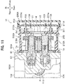
- a vehicle brake fluid pressure control device U1 of the present embodiment has such a structure that the solenoid valves V1 and V2 and the motor M are accommodated in a housing 202A of an electronic control unit 200A which is an electric component assembly as shown in FIGS. 11 and 12 .
- the vehicle brake fluid pressure control device U1 includes a base body 100A to which the solenoid valves V1 and V2 for one brake system, a motor M, a reciprocating pump P and the like are fitted.
- the base body 100A is a metal component formed in a substantially rectangular parallelepiped (see FIGS. 12 and 13 ), and is formed therein with a brake fluid passage, i.e., oil passage (not shown).
- a plurality of holes such as bottomed mounting holes 110 with which the solenoid valves V1 and V2 are mounted, bottomed mounting holes (not shown) with which the motor M is mounted, and the like are formed on the front surface 101A which is one of surfaces, or one side, of the base body 100A as shown in FIG. 13 . That is, the front surface 101A of the base body 100A has mounting holes for the solenoid valves V1 and V2 and the motor M collectively formed therein.
- Coil assemblies 1 as electric components are mounted onto the respective solenoid valves V1 and V2. Each coil assembly 1 is electrically connected to a control board 201A (see FIG. 11 , hereinafter see the same) using press-fit terminals 10A, as described below.
- the motor M is integrally fixed to a front surface 101A of the base body 100A with bolts 120 (see FIG. 21 ).
- a pair of motor bus bars M11 are provided on a bottom portion of the cover of the motor M, and connected respectively to the bus bar terminal portions 250 provided on an inner wall (first accommodation chamber 215A) of the housing 202A, as shown in FIG. 12 .
- the bus bar terminal portion 250A is provided upright thereon with a press-fit terminal 251 for connecting to the control board 201A.
- the electronic control unit 200A includes a coil assembly 1A, a control board 201A, a housing 202A, and a lid 203.
- the coil assembly 1A is fixed to the housing 202A by insertion and press-fitting as in the first embodiment.
- the housing 202A accommodates the coil assembly 1A and the control board 201A, as well as the solenoid valves V1 and V2 and the motor M protruding from the base body 100A.
- the control board 201A regulates energization of the coil assembly 1A and the motor M to control opening and closing operation of the solenoid valves V1 and V2 and drive of the motor M.
- the housing 202A is a box integrally fixed to the front surface 101A of the base body 100A while covering the solenoid valves V1 and V2 and the motor M protruding from the front surface 101A of the base body 100A, as shown in FIG. 11 .
- the housing 202A is integrally molded of a plastic material as in the first embodiment and fitted thereto with the control board 201A and the coil assembly 1A.
- the housing 202A is open respectively at a front surface on the opposite side to the base body 100A and a rear surface on the same side as the base body 100A.
- the housing 202A includes a plate-like bottom portion 210A, a first peripheral wall portion 211A provided on the front surface of the bottom portion 210A, and a second peripheral wall portion 212A provided on the rear surface of the bottom portion 210A, as shown in FIG. 12 .
- the bottom portion 210A has a substantially rectangular outer shape.
- the first peripheral wall portion 211A extends forward from the peripheral edge portion of the bottom portion 210A, and has an outer periphery exhibiting a substantially rectangular shape.
- the first peripheral wall portion 211A defines a first accommodation chamber 215A (see FIG. 11 ) that accommodates the substantially rectangular control board 201A.
- the second peripheral wall portion 212A extends rearward from the rear surface of the bottom portion 210A, and is substantially heptagonal in an outer peripheral shape (see FIG. 15 ).
- the second peripheral wall 212A defines a second accommodation chamber 216A (see FIG. 11 ) that accommodates the coil assembly 1A and the motor M.
- the second peripheral wall portion 212A is formed longer in the front-rear direction than that of the first embodiment in order to be able to accommodate the motor M (or a motor cover) longer in the axial direction (front-rear direction) than the coil assembly 1A.
- the first accommodation chamber 215A and the second accommodation chamber 216A communicate with each other through the opening 256 of the bottom portion 210A, as shown in FIGS. 11 , 12 , and 15 . That is, no partition wall exists between the first accommodation chamber 215A and the second accommodation chamber 216A. Also in the present embodiment, the housing 202A has a structure in which no partition wall exists in this way, so that the coil assembly 1A and the motor M can be disposed to extend from the second accommodation chamber 216A through the first accommodation chamber 215A as shown in FIG. 11 . That is, the space in the axial direction (front-rear direction) is effectively used for downsizing, while accommodating the motor M (motor cover) longer than the coil assembly 1A in the front-rear direction.
- An uneven-shaped holding wall 220A is formed on the inner surface on the rear side of the second peripheral wall portion 212A, as shown in FIG. 15 .
- the holding wall 220A includes the boss portions 221 protruding inward from the upper and lower sides of the second accommodation chamber 216A, and a holder 223A protruding inward from the left side.
- two mounting spaces 225A in total in which the coil assembly 1A can be mounted are formed between the holder 223A and the boss portions 221 adjacent to the holder 223A.
- the inner surface shape of the holding wall 220A in each mounting space 225A is the same as that of the first embodiment, and formed in a shape following the outer surface shape of the coil assembly 1A.
- each mounting space 225A a pair of groove portions 226 for positioning and fixing the coil assembly 1A in the mounting space 225A is concavely provided.
- the groove portions 226 are formed respectively at positions facing to each other of opposingly disposed potions of the holding wall 220A.
- Each groove portion 226 is provided with a protrusion 226a as shown in FIG. 18A .
- a plate-like terminal holder 240 is provided in each mounting space 225A, shown in FIG. 15 .
- the terminal holder 240 extends from the upper left side to the lower left side of the holding wall 220 so that the terminal holder 240 is arranged to each of the mounting spaces 225A.
- the terminal holder 240 is protrudingly provided with guide portions 241 having a substantially rectangular outer shape.
- the guide portion 241 have a slit-like insertion hole 242 formed (see FIG. 19 ).
- the insertion holes 242 are provided at respective positions corresponding to press-fit terminals 10A of the coil assembly 1A to be mounted in the mounting spaces 225A. This allows the press-fit terminal 10A to be inserted into each insertion hole 242.
- press-fit terminals 252 other than those of the coil assembly 1A are insertion-molded in the housing 202A at the upper and lower corners of the terminal holder 240, and guide portions 243 for supporting the press-fit terminals 252 are provided (see FIG. 12 ).
- the second peripheral wall portion 212A is formed at its rear end with a peripheral groove 228A.
- the peripheral groove 228A has an adhesive for fixing it to the front surface 101A of the base body 100A interposed.
- the housing 202A is liquid-tightly sealed to the front surface 101A of the base body 100A via the adhesive.
- the peripheral groove 228A and the ribs 25a abut onto a region indicated by an annular hatching line S11 and a region indicated by linear hatching lines S21 at positions sandwiching the solenoid valves V1 and V2 and corresponding to the ribs 25a as shown in FIG. 21 on the front surface 101A of the base body 100A, with the adhesive interposed. Note that the applications of the adhesive to the annular hatching line S11 and the linear hatching lines S21 are performed in the same process.
- the lid 203 is fixed to the opening on the front surface of the housing 202A opposite to the base body 100A.
- the coil assembly 1A of the present embodiment is different from the coil assembly 1 of the first embodiment in that the coil assembly 1A is provided with a press-fit terminal 10A having a longer total length as shown in FIGS. 16 and 17 . There is no change in the rest of the coil assembly 1A.
- the press-fit terminal 10A is a metal component partially insertion-molded on the terminal support portion 22b of the bobbin 2.
- the press-fit terminals 10A are disposed at a predetermined interval in the right-left direction, as shown in FIG. 16A .
- the press-fit terminals 10A are electrically connected respectively to the ends of the winding 51.
- the press-fit terminal 10A includes a plate-like base portion 11, a terminal portion 12A protruding upward from the upper portion of one end of the base portion 11, and a connection portion 13 protruding downward from the lower portion of the other end of the base portion 11, as shown in FIGS. 17A to 17C .
- the terminal portion 12A is formed to have its total length longer than that of the terminal portion 12 of the first embodiment (see FIGS. 7A to 7C ).
- the total length of the terminal portion 12A is set in accordance with the dimension in the front-rear direction of the second accommodation chamber 216A of the housing 202A. That is, because the present embodiment is configured to accommodate the motor M in the second accommodation chamber 216A, the second peripheral wall portion 212A is extended in the front-rear direction longer than that of the first embodiment, which makes the total length of the terminal portion 12A longer accordingly.
- the terminal portion 12A protrudes vertically upward (outward in the axial direction of the bobbin 2) from the upper side of one end of the base portion 11.
- the terminal portion 12A has in its middle portion a wide portion 18 formed wider than the rest of the terminal portion 12A.
- the wide portion 18 is held on the inner surface of the insertion hole 242 provided in the guide portion 241 of the terminal holder 240 in a state in which the coil assembly 1A is fitted into the mounting space 225A of the housing 202A (see FIG. 18B ). That is, the middle portion of the terminal portion 12A having a long total length is held by the housing 202A via the terminal holder 240.
- the coil assembly 1A is fitted into the housing 202A through the rear surface of the second accommodation chamber 216A, as shown in FIG. 18A .
- the coil assembly 1A is inserted into the mounting space 225A with the press-fit terminal 10A directed to the mounting space 225A and the side portion 33 of the yoke 3 directed to the reinforcing rib 227 in the mounting space 225A.
- the shape of the press-fit terminal 10A is simplified in FIG. 18A .
- the terminal portion 12A of the press-fit terminal 10A is inserted into the insertion hole 242 of the terminal holder 240.
- the terminal portion 12A can be smoothly inserted into the insertion hole 242, because the end portion 18A of the wide portion 18 of the press-fit terminal 10A has an arc-shaped chamfered shape at one end closer to the terminal portion 12A.
- the coil assembly 1A is further pushed in the fitting direction, and the ribs 25 are inserted into and press-fitted into the respective groove portions 226.
- This press-fitting can position and fix the coil assembly 1A at a predetermined position of the second accommodation chamber 216A of the housing 202A.
- each coil assembly 1A is fitted into the housing 202A, an adhesive is applied to the annular hatching line S11 and the linear hatching lines S21 on the front surface 101A of the base body 100A, which lines S11 and S21 correspond respectively to a housing adhesion margin S1 of the peripheral groove 228A of the housing 202A and an electric component adhesion margins S2 on the lower surface 25a of the ribs 25 of the coil assemblies 1A.
- the housing 202A is moved closer to the front surface 101A of the base body 100A, and the rear end of the housing 202A is brought contact onto the front surface 101A of the base body 100A while each coil assembly 1A is being mounted onto the solenoid valves V1 and V2 protruding from the front surface 101A.
- the yoke 3 when mounting each coil assembly 1A to the solenoid valves V1 and V2, the yoke 3 can move (to move in the direction orthogonal to the axial direction) with respect to the bobbin 2 fixed to the housing 202A. Accordingly, even if there is a slight positional deviation between the solenoid valves V1 and V2 and the coil assembly 1A, this positional deviation can be absorbed to mount each coil assembly 1A to the solenoid valves V1 and V2. That is, while keeping the state in which each press-fit terminal 10A is positioned at the predetermined position, the positional deviation of the coil assembly 1A with respect to the solenoid valves V1 and V2 can be absorbed to mount the coil assembly 1A.
- the control board 201A is fitted through the opening of the first accommodation chamber 215A which is open on the front surface of the housing 202A.
- each through-hole 201a of the control board 201A is aligned with a tip portion of the corresponding press-fit terminal 10A, and the control board 201A is pushed toward the coil assembly 1A.
- the terminal portion 12A of the press-fit terminal 10A is press-fitted into the through-hole 201a.
- the press-fit terminal 10A is held by the terminal support portion 22b of the coil assembly 1A, and keeps an upright posture on the terminal support portion 22b.
- the middle portion of the press-fit terminal 10A can be held on the housing 202A by the terminal holder 240.
- connection of the press-fit terminal 251 of the bus bar terminal portion 250 of the housing 202A and the press-fit terminals 253 of the connector portion 229 can be simultaneously performed as shown in FIG. 12 , when the control board 201A is fitted.
- an adhesive is applied to a groove 275 (see FIG. 12 ) in the front-end portion of the first accommodation chamber 215A to liquid-tightly fix the lid 203.
- an engaging portion 255 is provided at the front-end portion, and engaging the engaging portion 255 with a hook portion (not shown) on the lid 203 can facilitate positioning at the time of fitting. The fitting is completed as described above.
- the middle portion of the press-fit terminal 10A may be inserted into and held by the terminal holder 240 of the housing 202A. Thereby, even when the total length of the press-fit terminal 10A is long, its middle portion can be reliably held by the housing 202A, and therefore this prevents the press-fit terminal 10A from being bent and inclined, and thus to ensure the connection of the coil assembly 1A to the control board 201A.
- the coil assembly 1A can be secured to be connected to the control board 201A, so that the degree of freedom in a layout of the coil assembly 1A in the housing 202A is increased.
- the middle portion of the press-fit terminal 10A has a wide portion 18 wider than the other portions of the press-fit terminal 10A. Accordingly, the middle portion of the press-fit terminal 10A can be surely held on the inner surface of the insertion hole 242 via the wide portion 18. This may more effectively prevent the press-fit terminal 10A from being bent or inclined.
- the present invention is not limited to the configuration described in the embodiments and the configuration can be appropriately changed in the scope without departing from the spirit thereof. Moreover, it may be possible to add, delete, and replace a part of the configuration of the embodiments.
- the rib 25 is shown as having a rectangular parallelepiped shape, it is not limited thereto, and various shapes of ribs may be adopted.
- the number of the ribs 25 installed may be single or three or more.
- the ribs 25 are provided on the coil assembly 1 (1A) and the groove portion 226 is provided on the housing 202 (202A), on the contrary, the groove portion may be provided on the coil assembly 1 (1A) and the ribs may be provided on the housing 202 (202A).
- press-fit terminal 10 (10A) is used as a connection terminal
- any other terminal which can be pressure-connected such as a snap fit terminal, may be employed as a connection terminal.
- the press-fit terminal 10 may be any terminal in which the terminal portion 12 protrudes upward from the bobbin 2, and the connection portion 13 or the like of the press-fit terminal 10 may be disposed on a lateral side or the like of the bobbin 2.
- press-fit terminal 10 is described as insertion-molded in the bobbin 2, the press-fit terminal 10 is not limited thereto and may be attached to the bobbin 2 later.
- the present invention discloses the coil assembly 1 (1A) as an electric component, the present invention may be also suitably applied to other electric components fitted in the housing 202 (202A).
- the adhesive is applied to the front surface 101 (101A) of the base body 100 (100A), but may be applied first to the housing 202 (202A) and the coil assembly 1 (1A, electric component).
Abstract
Description
- The present invention relates to an electric component assembly and a vehicle brake fluid pressure control device.
- A conventional brake system of some vehicles such as a two-wheeled vehicle or a four-wheeled vehicle is known to be provided with a vehicle brake fluid pressure control device for controlling the brake fluid pressure applied to wheel brakes. Such a vehicle brake fluid pressure control device includes a base body in which a brake fluid passage is formed, and a solenoid valve attached to a surface of the base body. The surface of the base body has attached thereto an electric component assembly including a coil assembly as an electric component mounted on the solenoid valve and a housing covering the coil assembly. The coil assembly is connected to a control board disposed within the housing.
- The above-described vehicle brake fluid pressure control device controls energization of the coil assemblies to open and close the solenoid valve, and thereby the brake fluid pressure in the brake fluid passage is varied to control the braking force of the wheel brake.
- The coil assembly includes a yoke, a bobbin disposed in the yoke, and a coil wound around the bobbin.
- As a connection terminal connected to the coil, for example, one provided with a press-fit terminal as shown in PTL (Patent Literature) 1 is known. The coil assemblies and the control board are electrically connected by press-fitting and insertion-mounting the press-fit terminals into the insertion-mounting holes of the control board.
- In addition, a structure in which an electric component such as a coil assembly is fixed to a housing only by connection using a press-fit terminal or the like is also being studied in order to simplify the fitting structure.
- PTL 1: Japanese Patent No.
5261223 - However, the following problem might be caused in the structure in which electric component such as coil assembly is fixed to the housing only through the connection with the connection terminals such as press-fit terminal. For example, if an excessive external force acts on the press-fit terminal in the connection direction thereof, the terminal part press-fitted and insertion-mounted on the control board might be deformed to make the coil assemblies or the like drop off the control board.
- The present invention solves the problems described above by providing an electric component assembly and a vehicle brake fluid pressure control device which can suitably prevent the drop-off of the electric component while adopting a simple connection structure to the control board with the connection terminals.
- In order to solve the above problems, the present invention provides an electric component assembly, comprising: an electric component; and a housing in which the electric component is incorporated, wherein the electric component and the housing are fixed to one surface of a base body. The electric component includes a connection terminal that is press-fitted and insertion-mounted into a through-hole of a board provided in the housing, and an insertion direction of the connection terminal into the through-hole is the same as a fitting direction of the electric component to the housing. The electric component assembly includes a rib which is protrudingly provided on either one of an outer surface of the electric component intersecting the fitting direction and an inner surface of the housing facing the outer surface, and a groove portion which is provided as a recess on the other surface of the outer surface of the electric component and the inner surface of the housing and the rib is inserted into; and an inner surface of the groove portion is provided with a protrusion that abuts onto the rib.
- In the electric component assembly of the present invention, the electric component may be positioned in the housing by inserting the rib into the groove portion and making the rib abut onto the protrusion. Thereby, in the electric component assembly according to the present invention, the drop-off of the electric component can be suitably prevented while adopting a simple connection structure of the electronic component to the control board with the connection terminals.
- In the electric component assembly, the protrusion preferably protrudes on the inner surface of the groove portion. This configuration allows the rib to abut onto the protrusion and thereby to be press-fitted into the groove portion. This enables the electric component to be fixed to the housing, and the connection terminal to be accurately disposed at the predetermined positions of the housing. Therefore, the position setting of the connection terminals is made easy, and the connection terminal can be easily connected to the control board.
- In the electric component assembly described above, the connection terminal is preferably a press-fit terminal that can be more easily connected to the control board.
- In the electric component assembly described above, the electric component is a coil assembly configured to drive a solenoid valve. The coil assembly preferrably includes a bobbin; a coil including a winding around the bobbin; a yoke attached to the bobbin; and the connection terminal electrically connected to the winding.
- The present invention provides a vehicle brake fluid pressure control device, the device comprising the electric component assembly described above, being connected between a master cylinder and a wheel brake, and controlling a brake fluid pressure acting on the wheel brake. The vehicle brake fluid pressure control device has the solenoid valve attached to the base body and the coil assembly mounted on the solenoid valve.
- In the vehicle brake fluid pressure control device of the present invention, the electric component can be fixed at a predetermined position of the housing, and the connection terminal can be accurately disposed at the predetermined position. Therefore, fitting efficiency can be improved to reduce costs.
- The electric component assembly and the vehicle brake fluid pressure control device according to the present invention suitably prevents the drop-off of the electric component while adopting a simple connection structure of the electric component to the control board with the connection terminal.
-
-
FIG. 1 is a side sectional view of a vehicle brake fluid pressure control device provided with an electric component assembly according to a first embodiment of the present invention. -
FIG. 2 is an exploded perspective view of the vehicle brake fluid pressure control device according to the first embodiment of the present invention. -
FIG. 3 is a rear view of the electric component assembly of the first embodiment. -
FIG. 4 is a rear view of a housing which is a component of the electric component assembly of the first embodiment. -
FIGS. 5A and 5B are views showing a coil assembly of the first embodiment, whereFIG. 5A shows a perspective view seen from the side where the yoke is disposed, andFIG. 5B shows an enlarged perspective view showing a press-fit terminal portion. -
FIGS. 6A to 6E are views showing the coil assembly when the side on which a yoke is disposed is regarded as the rear surface, whereFIG. 6A shows a plan view,FIG. 6B shows a rear view,FIG. 6C shows a right-side view,FIG. 6D shows a longitudinal sectional view, andFIG. 6E shows a bottom view. -
FIGS. 7A to 7D are views showing a press-fit terminal which is a component of the coil assembly of the first embodiment, whereFIG. 7A shows a front view,FIG. 7B shows a left side view,FIG. 7C shows a rear view, andFIG. 7D shows an enlarged rear view of the main portion. -
FIGS. 8A and 8B are views showing the electric component assembly of the first embodiment, whereFIG. 8A shows a partial perspective view showing a state when the coil assembly is being incorporated to the housing, andFIG. 8B shows a partial perspective view showing a state after the fitting. -
FIG. 9 is a rear view of the electric component assembly of the first embodiment, showing a housing adhesion margin and an electric component adhesion margin in the electric component assembly. -
FIG. 10 is a front view of a base body used for the vehicle brake fluid pressure control device of the first embodiment, showing a bonding area in the base body. -
FIG. 11 is a side sectional view of a vehicle brake fluid pressure control device provided with an electric component assembly according to a second embodiment of the present invention. -
FIG. 12 is a perspective view of the vehicle brake fluid pressure control device according to the second embodiment of the present invention, showing a layout within a housing of the vehicle brake fluid pressure control device. -
FIG. 13 is a front view of a base body used for the vehicle brake fluid pressure control device according to the second embodiment of the present invention, showing a mounting surface on which the electric component assembly is mounted. -
FIG. 14 is a rear view of the electric component assembly of the second embodiment. -
FIG. 15 is a rear view of the housing in the second embodiment. -
FIGS. 16A and 16B are views showing a coil assembly of the second embodiment, whereinFIG. 16A shows a perspective view seen from the side where the yoke is disposed, andFIG. 16B shows an enlarged perspective view showing a press-fit terminal portion. -
FIGS. 17A to 17C are views showing the press-fit terminal in the second embodiment, whereFIG. 17A is a front view,FIG. 17B is a left side view, andFIG. 17C is a rear view. -
FIGS. 18A and 18B are views showing the electric component assembly of the second embodiment, whereFIG. 18A is a partial perspective view showing a state when the coil assembly is being incorporated to the housing, andFIG. 18B is a partial perspective view showing a state after the fitting. -
FIG. 19 is an enlarged cross-sectional view showing a state of the press-fit terminals held by the terminal holder of the housing. -
FIG. 20 is a rear view of the electric component assembly of the second embodiment, showing a housing adhesion margin and an electric component adhesion margin in the electric component assembly. -
FIG. 21 is a front view of the base body used for the vehicle brake fluid pressure control device of the second embodiment, showing a bonding area in the base body. - Hereinafter, embodiments of the present invention are described in detail with reference to the drawings as appropriate. In the following description, front / rear / up (upper) / down (lower) of a vehicle brake fluid pressure control device are referenced to the directions shown in
FIG. 1 , and right / left thereof are referenced to the directions shown inFIG. 3 andFIG. 4 are set as a basis. Moreover, front / rear / right / left / up (upper) / down (lower) of the coil assembly that is an electric component are referenced to the directions shown inFIG. 5A , the purpose of which, however, is not to limit the fitting direction of the coil assembly to the vehicle brake fluid pressure control device. - In this embodiment, a description is given as an example of a case that the electric component assembly of the present invention is applied to a vehicle brake fluid pressure control device for a two-wheeled vehicle provided with two brake systems. Of course, the present invention may be applied to a vehicle brake fluid pressure control device for a four-wheeled vehicle.
- A vehicle brake fluid pressure control device U is connected between a master cylinder (not shown) and a wheel brake (not shown), and controls the brake fluid pressure acting on the wheel brake.
- As shown in
FIGS. 1 and2 , the vehicle brake fluid pressure control device U includes abase body 100 in which solenoid valves V1 and V2 for two brake systems, a motor M, a reciprocating pump P, and other elements are fitted. The vehicle brake fluid pressure control device U includes anelectronic control unit 200 as an electric component assembly provided with acontrol board 201 as an electric component that detects a motion of a vehicle body to control opening and closing of the solenoid valves V1 and V2 and operation of the motor M. Thebase body 100 may be fitted with various sensors such as a pressure sensor in addition to the solenoid valves V1 and V2. - The
base body 100 is formed with a brake fluid passage (an oil passage), which is not shown. The vehicle brake fluid pressure control device U is configured to change the brake fluid pressure in the brake fluid passage by making thecontrol board 201 operate the solenoid valves V1 and V2 and the motor M based on the behavior of the vehicle body. - The
base body 100 is a metal component formed in a substantially rectangular parallelepiped (seeFIG. 2 ), and formed with a brake fluid passage (oil passage), which passage is not shown in the figures. - A
front surface 101 that is one of surfaces, or one side, of thebase body 100 has a plurality of bottomed mountingholes 110 and the like formed, into which holes 110 the solenoid valves V1 and V2 are mounted. Note that the number of solenoid valves V1 and V2 used varies depending on, for example, a type of the target vehicle such as four-wheeled or two-wheeled, and a difference in function of the vehicle brake fluid pressure control device U, and the like. Each of the solenoid valves V1 and V2 of the present embodiment is fitted therein with acoil assembly 1 as an electric component. The solenoid valve V1 is, for example, a normally open solenoid valve. The solenoid valve V2 is, for example, a normally closed solenoid valve. Eachcoil assembly 1 is electrically connected to thecontrol board 201 using a press-fit terminal 10 as described below. - As shown in
FIG. 2 , anupper surface 103 of thebase body 100 hasinlet ports 111,outlet ports 112 to which pipes leading to a wheel brake (not shown) are connected, and the like formed. - Further, a lower surface of the
base body 100 has a reservoir hole into which some of reservoir components (not shown) making up a reservoir are fitted, and the like formed. - Furthermore, a
side surface 104 of thebase body 100 is formed with apump hole 113, in which the reciprocating pump P is fitted, and the like. - Note that holes provided in the
base body 100 communicate with each other directly or through the brake fluid passages (not shown) formed inside thebase body 100. - The motor M is an electrically-driven component that is a power source for the reciprocating pump P. The motor M is integrally fixed to a
rear surface 102 that is other surface of thebase body 100. The motor M drives the reciprocating pump P. - The motor M is connected to a motor bus bar (not shown) for supplying power to a rotor. The motor bus bar is inserted into a terminal hole 115 (see
FIG. 2 ) of thebase body 100 and electrically connected through a bus bar terminal portion 230 (seeFIGS. 2 and4 ) of theelectronic control unit 200 to the control board 201 (seeFIG. 1 , the same applies hereinafter). Press-fit terminals (not shown) are connected to the busbar terminal portion 230 in a manner of protruding toward the front side. The motor bus bar connected to the busbar terminal portion 230 is electrically connected to thecontrol board 201 via the press-fit terminals. - The
electronic control unit 200 includes thecoil assemblies 1, thecontrol board 201, ahousing 202, and alid 203. Thecoil assemblies 1 are fixed by insertion to thehousing 202 as described below. Thehousing 202 accommodates thecoil assemblies 1 and thecontrol board 201, as well as the solenoid valves V1 and V2, and the motor bus bar (not shown) protruding from thebase body 100. Details of the mounting structure of thecoil assemblies 1 to thehousing 202 are described below. - The
control board 201 includes a substantially rectangular board on which an electric circuit is printed and electronic components such as a semiconductor chip mounted. Thecontrol board 201 is formed with a plurality of through-holes 201a into which the press-fit terminals 10 provided in thecoil assembly 1 are press-fitted. Thecontrol board 201 performs control based on information obtained from sensors and the like (not shown) provided in the vehicle and a program stored in advance. Specifically, thecontrol board 201 regulates energization of the coil assemblies 1 (seeFIG. 2 ) and the motor M to control the opening and closing operations of the solenoid valves V1 and V2 and the driving operation of the motor M. The sensors include various sensors, such as an angular velocity sensor, an acceleration sensor, and the like, as well as the pressure sensors. - The
housing 202 is a box integrally fixed to thefront surface 101 of thebase body 100 while covering the solenoid valves V1 and V2, and the like protruding from thefront surface 101 of thebase body 100 as shown inFIG. 1 . Thehousing 202 is integrally formed from plastic material. Thehousing 202 is fitted with thecontrol board 201 and thecoil assemblies 1. - The
housing 202 is open respectively at a front surface far from thebase body 100 and a rear surface near thebase body 100. - The
housing 202 includes a plate-like bottom portion 210, a firstperipheral wall portion 211 provided on a front surface of thebottom portion 210, and a secondperipheral wall portion 212 provided on a rear surface of thebottom portion 210, as shown inFIG. 2 . - The
bottom portion 210 has a substantially rectangular outer shape. The firstperipheral wall portion 211 extends forward from the periphery of thebottom portion 210, and is substantially rectangular in its outer peripheral shape. The firstperipheral wall portion 211 defines a first accommodation chamber 215 (seeFIG. 1 ) in which the substantiallyrectangular control board 201 is accommodated. - The second
peripheral wall portion 212 extends rearward from the rear surface of thebottom portion 210, and is generally octagonal in its outer peripheral shape. The secondperipheral wall portion 212 defines a second accommodation chamber 216 (seeFIG. 1 ) in which thecoil assemblies 1 are accommodated. - The
first accommodation chamber 215 and thesecond accommodation chamber 216 communicate with each other as shown inFIGS. 1 and3 . It means that no partition walls are present between thefirst accommodation chamber 215 and thesecond accommodation chamber 216. Thehousing 202 is structured to have no partitions as described above so as to allow thecoil assemblies 1 to be disposed extending from thesecond accommodation chamber 216 through to thefirst accommodation chamber 215 as shown inFIG. 1 . This allows thehousing 202 to suitably accommodate thecoil assemblies 1 while being downsized in the front-rear direction. - The second
peripheral wall portion 212 has an uneven-shapedholding wall 220 formed on its inner surface, as shown inFIG. 4 . The holdingwall 220 includesboss portions 221 protruding inward at right and left sides, aterminal boss portion 222 protruding inward at the upper side, and aholder 223 protruding inward at the lower side, of thesecond accommodation chamber 216. Inside the holdingwall 220, there are formed four mountingspaces 225 in total in which thecoil assemblies 1 are mounted between theboss portions 221 and theterminal boss 222 adjacent to each other and between theboss portions 221 and theholder 223 adjacent to each other. The inner surface shape of the holdingwall 220 at each mountingspace 225 is the same as each other, and is formed in a shape following the outer surface shape of thecoil assemblies 1. Each mountingspace 225 is concavely provided at its open-end portion with a pair ofgroove portions 226 for positioning and fixing thecoil assembly 1. Thegroove portions 226 in each mountingspace 225 are formed at opposite potions to each other of the opposingly disposed portions of the holdingwall 220. As shown inFIG. 8A , the inner surface of eachgroove portion 226 is formed with aprotrusion 226a that gives a press-fit effect at the time of fitting. Theprotrusion 226a protrudes toward the inside of thegroove portion 226, and abuts onto a rib 25 (seeFIG. 8B ) which is inserted into thegroove portion 226 as described below. Note that reinforcingribs 227 are formed on the inner surface of the holdingwall 220 as shown inFIG. 2 . - The second
peripheral wall 212 is formed at its rear end portion with aperipheral groove 228, in which an adhesive is applied to fix thehousing 202 to thefront surface 101 of thebase body 100. Thehousing 202 is liquid-tightly sealed to thefront surface 101 of thebase body 100 using the adhesive. Theperipheral groove 228 and theribs 25 abut onto an annular region indicated by a hatching line S11 (seeFIG. 10 ) and linear regions indicated by hatching lines S21 (seeFIG. 10 ) at positions corresponding to theribs 25 and sandwiching the solenoid valves V1 and V2 in a state of the adhesive being interposed, which hatching lines are shown on thefront surface 101 of thebase body 100 inFIG. 2 . Note that applications of the adhesive to the annular hatching line S11 and the linear hatching lines S21 are performed in the same process. - The
housing 202 is fixed to thebase body 100 by inserting fixing screws (not shown) through theboss portions 221 of the holdingwall 220 of thesecond accommodation chamber 216 and screwing the fixing screws into screw holes 116 (seeFIGS. 2 and10 ) of thebase body 100. - The
lid 203 is a lid made of plastic configured to seal an opening of the front surface of thehousing 202 opposite to thebase body 100. Thelid 203 is fixed to the front-end surface of thehousing 202 by means such as welding, bonding, screw fastening. - The
coil assembly 1 includes abobbin 2, acoil 50, ayoke 3, and the press-fit terminal 10 as a connection terminal, as shown inFIGS. 5A and6A to 6E . Thecoil assembly 1 is an electric component accommodated in thehousing 202 while surrounding the solenoid valves V1 and V2 as shown inFIG. 1 . Thecoil assembly 1 is a solenoid coil that generates a magnetic field around the solenoid valves V1 and V2 by having thecoil 50 energized by thecontrol board 201 through the press-fit terminals 10. Thecoil assembly 1 is fixed to thefront surface 101 of thebase body 100 via an adhesive as described below. - The
bobbin 2 is a plastic component (insulating component) in whichflange portions cylindrical portion 21 as shown inFIG. 6D . Thecylindrical portion 21 has acircular insertion hole 21a as a bobbin side insertion hole penetrating the central portion thereof. Theinsertion hole 21a communicates with an upperyoke receiving portion 22c formed in anupper flange portion 22 and ahole portion 22a of theupper flange portion 22. In addition, theinsertion hole 21a communicates with a loweryoke receiving portion 23a formed in thelower flange portion 23. Theinsertion hole 21a has an inner diameter D1. As shown inFIGS. 6A and 6E , theflange portions coil 50, and a rear portion formed in a substantially rectangular shape in a planar view corresponding to the shape of the yoke. Note that the inner diameter of thehole portion 22a of theflange portion 22 is larger than the inner diameter D1 of theinsertion hole 21a. - As shown in
FIG. 6D , theupper flange portion 22 is formed thicker in the upper-lower direction than thelower flange portion 23. Theupper flange portion 22 is formed its inside with the upperyoke receiving portion 22c capable of receiving theupper portion 31 of theyoke 3. The upperyoke receiving portion 22c is open at the rear surface and the front surface of theupper flange portion 22. Theupper portion 31 of theyoke 3 is received in the upperyoke receiving portion 22c from the rear surface of theupper flange portion 22. - The upper
yoke receiving portion 22c has a predetermined clearance between itself and theupper portion 31 of the receivedyoke 3 in a direction orthogonal to the axial direction of the bobbin 2 (horizontal direction). This allows theupper portion 31 of theyoke 3 to move within the horizontal direction due to the clearance provided in the upperyoke receiving portion 22c. - Note that since the
flange portion 22 covers substantially the entireupper portion 31 of theyoke 3, theflange portion 22 is excellent in insulation. - As shown in
FIG. 6C , twoprotrusions 22e (only one side is shown) are formed on the rear edge portion of theupper flange 22 at a predetermined interval in the right-left direction. Theprotrusion 22e is a plate-like portion that protrudes rearward from the rear edge portion of theupper flange portion 22 and is formed rectangular in a planar view. - Further, as shown in
FIGS. 5A and 5B ,terminal support portions 22b for supporting thebase portions 11 of the two press-fit terminals 10 are formed on the right and left rear portions of theupper flange portion 22. The press-fit terminal 10 is partially embedded in theterminal support portion 22b by insert molding. That is, theterminal support portion 22b (the upper flange portion 22) works as an insulator of the press-fit terminal 10. - The
upper portion 31 of theyoke 3 received in the upperyoke receiving portion 22c is disposed under theterminal support portion 22b. That is, the two press-fit terminals 10 are supported by theupper portion 31 of theyoke 3 via theterminal support portions 22b. Meanwhile, theterminal support portions 22b cover portions of theupper portion 31 of theyoke 3, which portions support the press-fit terminals 10. This provides insulation between the press-fit terminals 10 and theyoke 3. - As shown in
FIG. 6D , a loweryoke receiving portion 23a capable of receiving thelower portion 32 of theyoke 3 is formed inside thelower flange portion 23. The loweryoke receiving portion 23a is open at the rear surface and the lower surface of thelower flange portion 23. That is, thelower portion 32 of theyoke 3 is exposed at the lower surface of the coil assembly 1 (seeFIG. 6E ). Thelower portion 32 of theyoke 3 is received in the loweryoke receiving portion 23a from the rear surface of thelower flange portion 23. - As shown in
FIG. 6E , curvedconvex portions 23b protruding inward are formed at the right and left portions facing each other on the inner surface of the loweryoke receiving portion 23a. The loweryoke receiving portion 23a has a predetermined clearance between itself and thelower portion 32 of the receivedyoke 3 in the direction orthogonal to the axial direction of the bobbin 2 (horizontal direction) similarly to the upperyoke receiving portion 22c described above. This makes thelower portion 32 of theyoke 3 movable in the horizontal direction within the loweryoke receiving portion 23a due to the clearance. - Quadrangular-prism shaped
ribs 25 are formed on the right- and left-side surfaces of the rear side of the lower flange portion 23 (the outer surface of thecoil assembly 1 intersecting with the fitting direction). Theribs 25 work as fitting portions (positioning portions) when thecoil assembly 1 is fitted to thesecond accommodation chamber 216 of the housing 202 (seeFIG. 3 ). Specifically, theribs 25 are press-fitted into thegroove portions 226 provided in the mountingspace 225 of thesecond accommodation chamber 216, as shown inFIGS. 2 and3 . Then, theribs 25 abut onto theprotrusions 226a of thegroove portions 226, and theribs 25 are press-fitted into thegroove portions 226. This press-fitting restricts the movement of thecoil assembly 1 in a direction intersecting the fitting direction into the housing 202 (the arrow direction inFIG. 8A , the axial direction of the coil assembly 1) and rotation of thecoil assembly 1 around an axis parallel to the fitting direction. - At the same time, the
rib 25 also works as an electric component adhesion margin S2 (seeFIG. 9 ) for fixing thecoil assembly 1 to thefront surface 101 of thebase body 100 with an adhesive. Specifically, thelower surface 25a of therib 25 is disposed flush with arear surface 220a of the holdingwall 220 in a state of therib 25 being press-fitted into thegroove portion 226, as shown inFIG. 8B . This allows thelower surface 25a of therib 25 to abut onto thefront surface 101 of thebase body 100, and works as the electric component adhesion margin S2 for fixing thecoil assembly 1 with an adhesive. - Note that the
ribs 25 may be, for example inserted into a groove portion provided in an intermediate wall portions (not shown) provided inside thehousing 202. - Here, the adhesive is not limited to one that is interposed only on the
lower surface 25a of therib 25, but may be configured to be interposed ranging from therib 25 to the lower surface of thelower portion 32 of theyoke 3. Or, the adhesive may be interposed partially on thelower surface 25a of therib 25. In any case, the adhesive may be interposed so that thecoil assembly 1 is fixed to thefront surface 101 of thebase body 100 by the adhesive. - The
bobbin 2 as described above is produced, for example, by injection molding or the like. At the same time as thebobbin 2 is injection-molded, the press-fit terminals 10 are insertion-molded into a state of being integrally joined to theflange portion 22. - The
yoke 3 is a member attached to thebobbin 2 and formed of magnetic metal material. Theyoke 3 is composed of anupper portion 31, alower portion 32, and aside portion 33 connecting theupper portion 31 and thelower portion 32, as shown inFIGS. 5A and6D . Theyoke 3 is formed in a substantially U-shape in a longitudinal cross section (seeFIG. 6D ). - The
upper portion 31 is a portion received in the upperyoke receiving portion 22c of theupper flange portion 22 of thebobbin 2. Theupper portion 31 has the same outer shape as theupper flange portion 22 of thebobbin 2 and has a front portion formed in a semicircular shape and a rear portion formed in a substantially rectangular shape. Theupper portion 31 is adapted to be received in the upperyoke receiving portion 22c with the above-described clearance, and movable in the horizontal direction with respect to the upperyoke receiving portion 22c. - Note that the
upper portion 31 has the outer shape formed to be slightly smaller in size than thelower portion 32, so that the upper and lower portions can be easily distinguished at the time of fitting work. - The
upper portion 31 is received in the upperyoke receiving portion 22c and thereby disposed under the press-fit terminals 10 through theupper flange portion 22. That is, theupper portion 31 supports the press-fit terminals 10 (specifically,terminal portions 12 and the base portions 11) on an imaginary extension in the axial direction from theterminal portion 12. - The
lower portion 32 is a portion received in the loweryoke receiving portion 23a of theflange portion 23 on the lower side of the bobbin 2 (seeFIG. 6D ). Thelower portion 32 has a front portion formed in a semicircular shape and a rear portion formed in a substantially rectangular shape, similarly to the outer shape of theupper portion 31. - The
lower portion 32 hasconcave portions 32b formed at portions facing theconvex portions 23b of the loweryoke receiving portion 23a, as shown inFIG. 6E . Theconvex portions 23b of the loweryoke receiving portion 23a are adapted to be loosely fitted in theconcave portions 32b of the lower portion 32 (fitted in a gap) in a state of thelower portion 32 being received in the loweryoke receiving portion 23a. Thelower portion 32 is adapted to be received in the loweryoke receiving portion 23a with a clearance therebetween, and is movable in the horizontal direction with respect to the loweryoke receiving portion 23a with theconvex portions 23b loosely fitted to theconcave portions 32b as described above. That is, theconvex portion 23b is fitted in theconcave portion 32b while the horizontal movement described above is allowed. - The
yoke 3 has acircular insertion hole 31a in theupper portion 31 and acircular mounting hole 32a in thelower portion 32 as insertion holes formed at the yoke-side, as shown inFIG. 6D . Theseinsertion holes insertion hole 21a of thebobbin 2 and the inner diameter D2 of theinsertion holes yoke 3 described above is set such that the inner diameter D1 > the inner diameter D2, that is, the inner diameter D1 of thebobbin 2 is larger than the inner diameter D2 on theyoke 3. - Two press-
fit terminals 10 are metal components that are partially insertion-molded in theterminal support portions 22b (bobbin 2) as shown inFIG. 5B . The two press-fit terminals 10 are disposed at a predetermined interval in the right-left direction, as shown inFIG. 5A . The respective two press-fit terminals 10 are electrically connected to the ends of the winding 51. - The press-
fit terminal 10 includes a plate-like base portion 11, aterminal portion 12 protruding upward from the upper portion of one end of thebase portion 11, and aconnection portion 13 protruding downward from a lower portion of the other end of thebase portion 11, as shown inFIGS. 7A to 7D . - Most of the
base portion 11 is embedded in theterminal support portion 22b, as shown inFIG. 5B . The upper portion of thebase portion 11 is exposed from theterminal support portion 22b. Thebase portion 11 has aninsertion hole 11a that allows plastic to enter therein at a time of molding, as shown inFIG. 7A . Thebase portion 11 is reinforced and supported by a reinforcingrib 22d provided on theterminal support portion 22b as shown inFIG. 5B . - The
terminal portion 12 vertically protrudes upward (outward in the axial direction of the bobbin 2) from the upper portion of one end of thebase portion 11. That is, theterminal portion 12 extends upward above theupper flange 22. The tip of theterminal portion 12 bulges in an annular shape to be press-fitted into the through-hole 201a (seeFIG. 1 ) of the control board 201 (seeFIG. 1 ). - The
connection portion 13 is a portion to which the winding 51 of thecoil 50 is connected. Theconnection portion 13 is formed such that the plate thickness of thecontact portion 14 that contacts with the winding 51 is thinner than the plate thickness of other portions of theconnection portion 13. To be more specific, the press-fit terminal 10 which is easily restricted in thickness due to press-fitting is configured to be thinner at theconnection portion 13 that is connected to the winding 51 so that the coating of the winding 51 is scraped off by contact. - The
contact portion 14 is formed with agroove 15 having a substantially V-shaped cross section, as shown inFIG. 7D . The upper edge of thegroove 15 extends in a rounded shape. A pair ofstep portions 16 protruding toward the inside (the inner side) of thegroove 15 is formed at opposing portions to each other on the inner surface of thegroove 15. Agroove 15b is formed narrower in width at thestep portions 16. A width L1 (the width in the right-left direction) of thegroove 15b at thestep portion 16 of thegroove 15 is formed smaller than the wire diameter D3 of the winding 51 (diameter of the wire with coating). Thegroove 15 is formed narrower toward thedeepest portion 15c. - The
connection portion 13 has at its lower side portion aprotrusion 17 between which and thegroove 15 the winding 51 is wounded, as shown inFIGS. 7A and 7C . Further, the lower end portion of theconnection portion 13 is formed with a hook-shapedportion 13b that protrudes like a hook toward theterminal support portion 22b (seeFIG. 5B ). The hook-shapedportion 13b, which is not shown, is buried in theterminal support portion 22b (seeFIG. 5B ). - The press-
fit terminal 10 is produced by, for example, pressing (press punching). Thethin contact portion 14 is formed to be thin by being further pressed after the press-punching. Thereafter, thegroove 15 is punched to be formed. Note that thecontact portion 14 may be formed by pressing simultaneously with press punching, or may be formed first by pressing and then punching. - The
coil 50 is formed with the winding 51 around thecylindrical portion 21 of thebobbin 2, as shown inFIG. 5A . The winding 51 has its both ends wound around theconnection portions 13 of the press-fit terminals 10 to electrically connect thecoil 50 and each of the press-fit terminals 10. - The
coil assembly 1 is fitted into thehousing 202 through the rear surface of thesecond accommodation chamber 216 as shown inFIG. 8A . In this time, thecoil assembly 1 is inserted into the mountingspace 225 while directing the press-fit terminal 10 to the mountingspace 225 and theside portion 33 of theyoke 3 to the reinforcingrib 227 of the mountingspace 225. Note that the shape of the press-fit terminal 10 is simplified inFIG. 8A . - When the
coil assembly 1 is inserted in the fitting direction as shown by an outlined arrow inFIG. 8A , each of theribs 25 of theflange portion 23 of thebobbin 2 abuts onto the opening edge of eachgroove portion 226 of the mountingspace 225. In this state, thecoil assembly 1 is pushed in the fitting direction, and theribs 25 are respectively inserted and press-fitted into thegroove portions 226. - This insertion may position and fix the
coil assembly 1 at a predetermined position of thesecond accommodation chamber 216 of thehousing 202. - After the
coil assemblies 1 are fitted in thehousing 202, the adhesive is applied to the annular hatching line S11 and the linear hatching lines S21 on thefront surface 101 of thebase body 100, which lines S11 and S21 correspond respectively to the housing adhesion margin S1 in theperipheral groove 228 of thehousing 202 and the electric component adhesion margins S2 on thelower surfaces 25a of theribs 25 of thecoil assemblies 1. Thereafter, thehousing 202 is moved closer to thefront surface 101 of thebase body 100 whilecoil assemblies 1 are being mounted on the solenoid valves V1 and V2 protruding on thefront surface 101, and the rear end of thehousing 202 is brought into contact with thefront surface 101 of thebase body 100. This results in bonding of thehousing 202 andcoil assemblies 1 to thefront surface 101 of thebase body 100 with the adhesive interposed between thebase body 100 and the housing adhesion margin S1 and the electric component adhesion margins S2. Thereafter, fixing screws (not shown) inserted into theboss portions 221 of the holdingwall 220 of thesecond accommodation chamber 216 are screwed into the screw holes 116 (seeFIG. 2 ) of thebase body 100. Thereby, thehousing 202 andcoil assemblies 1 are fixed to thefront surface 101 of thebase body 100. - Note that the inner diameter D1 of the
insertion hole 21a of thebobbin 2 is larger than the inner diameter D2 of theinsertion holes yoke 3. This allows to move the yoke 3 (move in the direction orthogonal to the axial direction) with respect to thebobbin 2 fixed to thehousing 202 when mountingcoil assemblies 1 to the solenoid valves V1 and V2. Accordingly, even if there are slight relative positional deviations between the solenoid valves V1 and V2 andcoil assemblies 1, these positional deviations can be absorbed so that thecoil assemblies 1 can be mounted to the solenoid valves V1 and V2. That is, thecoil assemblies 1 may be mounted, while absorbing the positional deviations between thecoil assemblies 1 and the solenoid valves V1, V2 and keeping the press-fit terminals 10 positioned at the predetermined locations. - After the
housing 202 is fitted to thebase body 100, thecontrol board 201 is fitted through the opening of thefirst accommodation chamber 215 opened on the front side of thehousing 202. At this time of fitting, each through-hole 201a of thecontrol board 201 is aligned with the tip of the corresponding press-fit terminal 10, and thecontrol board 201 is pushed toward thecoil assemblies 1. Then, theterminal portions 12 of the press-fit terminals 10 are press-fitted into the through-holes 201a. Note that during this time of the fitting, the press-fit terminals 10 are held by theterminal support portion 22b of thecoil assembly 1 and keeps its upright posture on theterminal support portion 22b. This makes theterminal portions 12 of the press-fit terminals 10 secured to be press-fitted into the through-holes 201a. - Thereafter, the
lid 203 is liquid-tightly fixed to the front-end portion of thefirst accommodation chamber 215 by an adhesive or the like. - In the embodiment described above, the
coil assembly 1 can be positioned in thehousing 202 by inserting theribs 25 into thegroove portions 226 of thehousing 202 and making theribs 25 abut onto theprotrusions 226a. This allows this embodiment to include the simple connection structure of thecoil assembly 1 to thecontrol board 201 with the press-fit terminal 10 and suitably prevent the drop-off of thecoil assembly 1. - In addition, the
rib 25 may be press-fitted into thegroove portion 226 by making therib 25 abut onto theprotrusion 226a. This allows to fix thecoil assembly 1 to thehousing 202, and to accurately dispose the press-fit terminal 10 at the predetermined position of thehousing 202, and therefore, to facilitate the position setting of the press-fit terminal 10. - Moreover, the connection terminal is the press-
fit terminal 10, and therefore, the electrical connection between the press-fit terminal 10 and thecontrol board 201 can be easy and the fitting efficiency is improved. - Furthermore, the vehicle brake fluid pressure control device U of the present embodiment can fix the
coil assembly 1 at the predetermined position of thehousing 202, and accurately dispose the press-fit terminal 10 at the predetermined position, and therefore, improve the fitting efficiency and reduce the cost. - Next, a description is given of a vehicle brake fluid pressure control device to which the electric component assembly of the second embodiment is applied. The present embodiment is described by way of example about a case in which the electric component assembly is applied to a vehicle brake fluid pressure control device for a two-wheeled vehicle provided with one brake system. Of course, the present invention may be applied to a vehicle brake fluid pressure control device for a two-wheeled vehicle provided with two brake systems or a vehicle brake fluid pressure control device for a four-wheeled vehicle. Note that the same parts as those in the first embodiment are indicated by the same reference signs and detailed descriptions are omitted.
- A vehicle brake fluid pressure control device U1 of the present embodiment has such a structure that the solenoid valves V1 and V2 and the motor M are accommodated in a
housing 202A of anelectronic control unit 200A which is an electric component assembly as shown inFIGS. 11 and12 . - The vehicle brake fluid pressure control device U1 includes a
base body 100A to which the solenoid valves V1 and V2 for one brake system, a motor M, a reciprocating pump P and the like are fitted. - The
base body 100A is a metal component formed in a substantially rectangular parallelepiped (seeFIGS. 12 and13 ), and is formed therein with a brake fluid passage, i.e., oil passage (not shown). - A plurality of holes such as bottomed mounting
holes 110 with which the solenoid valves V1 and V2 are mounted, bottomed mounting holes (not shown) with which the motor M is mounted, and the like are formed on thefront surface 101A which is one of surfaces, or one side, of thebase body 100A as shown inFIG. 13 . That is, thefront surface 101A of thebase body 100A has mounting holes for the solenoid valves V1 and V2 and the motor M collectively formed therein.Coil assemblies 1 as electric components are mounted onto the respective solenoid valves V1 and V2. Eachcoil assembly 1 is electrically connected to acontrol board 201A (seeFIG. 11 , hereinafter see the same) using press-fit terminals 10A, as described below. - The motor M is integrally fixed to a
front surface 101A of thebase body 100A with bolts 120 (seeFIG. 21 ). A pair of motor bus bars M11 (seeFIGS. 13 and21 ) are provided on a bottom portion of the cover of the motor M, and connected respectively to the busbar terminal portions 250 provided on an inner wall (first accommodation chamber 215A) of thehousing 202A, as shown inFIG. 12 . The bus bar terminal portion 250A is provided upright thereon with a press-fit terminal 251 for connecting to thecontrol board 201A. - The
electronic control unit 200A includes acoil assembly 1A, acontrol board 201A, ahousing 202A, and alid 203. Thecoil assembly 1A is fixed to thehousing 202A by insertion and press-fitting as in the first embodiment. Thehousing 202A accommodates thecoil assembly 1A and thecontrol board 201A, as well as the solenoid valves V1 and V2 and the motor M protruding from thebase body 100A. - The
control board 201A regulates energization of thecoil assembly 1A and the motor M to control opening and closing operation of the solenoid valves V1 and V2 and drive of the motor M. - The
housing 202A is a box integrally fixed to thefront surface 101A of thebase body 100A while covering the solenoid valves V1 and V2 and the motor M protruding from thefront surface 101A of thebase body 100A, as shown inFIG. 11 . Thehousing 202A is integrally molded of a plastic material as in the first embodiment and fitted thereto with thecontrol board 201A and thecoil assembly 1A. - The
housing 202A is open respectively at a front surface on the opposite side to thebase body 100A and a rear surface on the same side as thebase body 100A. - The
housing 202A includes a plate-like bottom portion 210A, a firstperipheral wall portion 211A provided on the front surface of thebottom portion 210A, and a secondperipheral wall portion 212A provided on the rear surface of thebottom portion 210A, as shown inFIG. 12 . - The
bottom portion 210A has a substantially rectangular outer shape. The firstperipheral wall portion 211A extends forward from the peripheral edge portion of thebottom portion 210A, and has an outer periphery exhibiting a substantially rectangular shape. The firstperipheral wall portion 211A defines afirst accommodation chamber 215A (seeFIG. 11 ) that accommodates the substantiallyrectangular control board 201A. - The second
peripheral wall portion 212A extends rearward from the rear surface of thebottom portion 210A, and is substantially heptagonal in an outer peripheral shape (seeFIG. 15 ). The secondperipheral wall 212A defines asecond accommodation chamber 216A (seeFIG. 11 ) that accommodates thecoil assembly 1A and the motor M. The secondperipheral wall portion 212A is formed longer in the front-rear direction than that of the first embodiment in order to be able to accommodate the motor M (or a motor cover) longer in the axial direction (front-rear direction) than thecoil assembly 1A. - The
first accommodation chamber 215A and thesecond accommodation chamber 216A communicate with each other through theopening 256 of thebottom portion 210A, as shown inFIGS. 11 ,12 , and15 . That is, no partition wall exists between thefirst accommodation chamber 215A and thesecond accommodation chamber 216A. Also in the present embodiment, thehousing 202A has a structure in which no partition wall exists in this way, so that thecoil assembly 1A and the motor M can be disposed to extend from thesecond accommodation chamber 216A through thefirst accommodation chamber 215A as shown inFIG. 11 . That is, the space in the axial direction (front-rear direction) is effectively used for downsizing, while accommodating the motor M (motor cover) longer than thecoil assembly 1A in the front-rear direction. - An uneven-shaped
holding wall 220A is formed on the inner surface on the rear side of the secondperipheral wall portion 212A, as shown inFIG. 15 . The holdingwall 220A includes theboss portions 221 protruding inward from the upper and lower sides of thesecond accommodation chamber 216A, and aholder 223A protruding inward from the left side. Inside the holdingwall 220A, two mountingspaces 225A in total in which thecoil assembly 1A can be mounted are formed between theholder 223A and theboss portions 221 adjacent to theholder 223A. The inner surface shape of the holdingwall 220A in each mountingspace 225A is the same as that of the first embodiment, and formed in a shape following the outer surface shape of thecoil assembly 1A. At the open edge portion of each mountingspace 225A, a pair ofgroove portions 226 for positioning and fixing thecoil assembly 1A in the mountingspace 225A is concavely provided. In each mountingspace 225A, thegroove portions 226 are formed respectively at positions facing to each other of opposingly disposed potions of the holdingwall 220A. Eachgroove portion 226 is provided with aprotrusion 226a as shown inFIG. 18A . - A plate-
like terminal holder 240 is provided in each mountingspace 225A, shown inFIG. 15 . Theterminal holder 240 extends from the upper left side to the lower left side of the holdingwall 220 so that theterminal holder 240 is arranged to each of the mountingspaces 225A. - The
terminal holder 240 is protrudingly provided withguide portions 241 having a substantially rectangular outer shape. Theguide portion 241 have a slit-like insertion hole 242 formed (seeFIG. 19 ). The insertion holes 242 are provided at respective positions corresponding to press-fit terminals 10A of thecoil assembly 1A to be mounted in the mountingspaces 225A. This allows the press-fit terminal 10A to be inserted into eachinsertion hole 242. - Note that press-
fit terminals 252 other than those of thecoil assembly 1A are insertion-molded in thehousing 202A at the upper and lower corners of theterminal holder 240, and guideportions 243 for supporting the press-fit terminals 252 are provided (seeFIG. 12 ). - The second
peripheral wall portion 212A is formed at its rear end with aperipheral groove 228A. Theperipheral groove 228A has an adhesive for fixing it to thefront surface 101A of thebase body 100A interposed. Thehousing 202A is liquid-tightly sealed to thefront surface 101A of thebase body 100A via the adhesive. Theperipheral groove 228A and theribs 25a abut onto a region indicated by an annular hatching line S11 and a region indicated by linear hatching lines S21 at positions sandwiching the solenoid valves V1 and V2 and corresponding to theribs 25a as shown inFIG. 21 on thefront surface 101A of thebase body 100A, with the adhesive interposed. Note that the applications of the adhesive to the annular hatching line S11 and the linear hatching lines S21 are performed in the same process. - The
lid 203 is fixed to the opening on the front surface of thehousing 202A opposite to thebase body 100A. - The
coil assembly 1A of the present embodiment is different from thecoil assembly 1 of the first embodiment in that thecoil assembly 1A is provided with a press-fit terminal 10A having a longer total length as shown inFIGS. 16 and17 . There is no change in the rest of thecoil assembly 1A. - The press-
fit terminal 10A is a metal component partially insertion-molded on theterminal support portion 22b of thebobbin 2. The press-fit terminals 10A are disposed at a predetermined interval in the right-left direction, as shown inFIG. 16A . The press-fit terminals 10A are electrically connected respectively to the ends of the winding 51. - The press-
fit terminal 10A includes a plate-like base portion 11, aterminal portion 12A protruding upward from the upper portion of one end of thebase portion 11, and aconnection portion 13 protruding downward from the lower portion of the other end of thebase portion 11, as shown inFIGS. 17A to 17C . - The
terminal portion 12A is formed to have its total length longer than that of theterminal portion 12 of the first embodiment (seeFIGS. 7A to 7C ). The total length of theterminal portion 12A is set in accordance with the dimension in the front-rear direction of thesecond accommodation chamber 216A of thehousing 202A. That is, because the present embodiment is configured to accommodate the motor M in thesecond accommodation chamber 216A, the secondperipheral wall portion 212A is extended in the front-rear direction longer than that of the first embodiment, which makes the total length of theterminal portion 12A longer accordingly. - The
terminal portion 12A protrudes vertically upward (outward in the axial direction of the bobbin 2) from the upper side of one end of thebase portion 11. Theterminal portion 12A has in its middle portion awide portion 18 formed wider than the rest of theterminal portion 12A. As shown inFIG. 19 , thewide portion 18 is held on the inner surface of theinsertion hole 242 provided in theguide portion 241 of theterminal holder 240 in a state in which thecoil assembly 1A is fitted into the mountingspace 225A of thehousing 202A (seeFIG. 18B ). That is, the middle portion of theterminal portion 12A having a long total length is held by thehousing 202A via theterminal holder 240. - As with the first embodiment, the
coil assembly 1A is fitted into thehousing 202A through the rear surface of thesecond accommodation chamber 216A, as shown inFIG. 18A . At this time, thecoil assembly 1A is inserted into the mountingspace 225A with the press-fit terminal 10A directed to the mountingspace 225A and theside portion 33 of theyoke 3 directed to the reinforcingrib 227 in the mountingspace 225A. Note that the shape of the press-fit terminal 10A is simplified inFIG. 18A . - In the course that the
coil assembly 1A is inserted into the mountingspace 225A, theterminal portion 12A of the press-fit terminal 10A is inserted into theinsertion hole 242 of theterminal holder 240. In this case, theterminal portion 12A can be smoothly inserted into theinsertion hole 242, because theend portion 18A of thewide portion 18 of the press-fit terminal 10A has an arc-shaped chamfered shape at one end closer to theterminal portion 12A. Thereafter, thecoil assembly 1A is further pushed in the fitting direction, and theribs 25 are inserted into and press-fitted into therespective groove portions 226. - This press-fitting can position and fix the
coil assembly 1A at a predetermined position of thesecond accommodation chamber 216A of thehousing 202A. - After each
coil assembly 1A is fitted into thehousing 202A, an adhesive is applied to the annular hatching line S11 and the linear hatching lines S21 on thefront surface 101A of thebase body 100A, which lines S11 and S21 correspond respectively to a housing adhesion margin S1 of theperipheral groove 228A of thehousing 202A and an electric component adhesion margins S2 on thelower surface 25a of theribs 25 of thecoil assemblies 1A. Thereafter, thehousing 202A is moved closer to thefront surface 101A of thebase body 100A, and the rear end of thehousing 202A is brought contact onto thefront surface 101A of thebase body 100A while eachcoil assembly 1A is being mounted onto the solenoid valves V1 and V2 protruding from thefront surface 101A. This can bond thehousing 202A and eachcoil assembly 1A to thefront surface 101A of thebase body 100A with the adhesive interposed between thebase body 100A and the housing adhesion margin S1 and the electric component adhesion margin S2. Thereafter, the fixing screws 120 (seeFIG. 13 ) inserted into theboss portion 221 of the holdingwall 220A of thesecond accommodation chamber 216A are screwed into the screw holes 116 (seeFIG. 13 ) of thebase body 100A. This fixes thehousing 202A andcoil assemblies 1A to thefront surface 101A of thebase body 100A. - Also in the present embodiment, when mounting each
coil assembly 1A to the solenoid valves V1 and V2, theyoke 3 can move (to move in the direction orthogonal to the axial direction) with respect to thebobbin 2 fixed to thehousing 202A. Accordingly, even if there is a slight positional deviation between the solenoid valves V1 and V2 and thecoil assembly 1A, this positional deviation can be absorbed to mount eachcoil assembly 1A to the solenoid valves V1 and V2. That is, while keeping the state in which each press-fit terminal 10A is positioned at the predetermined position, the positional deviation of thecoil assembly 1A with respect to the solenoid valves V1 and V2 can be absorbed to mount thecoil assembly 1A. - After the
housing 202A is fitted to thebase body 100A, thecontrol board 201A is fitted through the opening of thefirst accommodation chamber 215A which is open on the front surface of thehousing 202A. At the time of fitting, each through-hole 201a of thecontrol board 201A is aligned with a tip portion of the corresponding press-fit terminal 10A, and thecontrol board 201A is pushed toward thecoil assembly 1A. Then, theterminal portion 12A of the press-fit terminal 10A is press-fitted into the through-hole 201a. Note that during this time, the press-fit terminal 10A is held by theterminal support portion 22b of thecoil assembly 1A, and keeps an upright posture on theterminal support portion 22b. Moreover, the middle portion of the press-fit terminal 10A can be held on thehousing 202A by theterminal holder 240. - Note that the connection of the press-
fit terminal 251 of the busbar terminal portion 250 of thehousing 202A and the press-fit terminals 253 of theconnector portion 229 can be simultaneously performed as shown inFIG. 12 , when thecontrol board 201A is fitted. - Thereafter, an adhesive is applied to a groove 275 (see
FIG. 12 ) in the front-end portion of thefirst accommodation chamber 215A to liquid-tightly fix thelid 203. Note that an engagingportion 255 is provided at the front-end portion, and engaging the engagingportion 255 with a hook portion (not shown) on thelid 203 can facilitate positioning at the time of fitting. The fitting is completed as described above. - The present embodiment described above provides the same advantageous effects as those described about the first embodiment.
- In addition, the middle portion of the press-
fit terminal 10A may be inserted into and held by theterminal holder 240 of thehousing 202A. Thereby, even when the total length of the press-fit terminal 10A is long, its middle portion can be reliably held by thehousing 202A, and therefore this prevents the press-fit terminal 10A from being bent and inclined, and thus to ensure the connection of thecoil assembly 1A to thecontrol board 201A. - Moreover, even if the
control board 201A and thecoil assembly 1A are spaced apart at a certain extent, thecoil assembly 1A can be secured to be connected to thecontrol board 201A, so that the degree of freedom in a layout of thecoil assembly 1A in thehousing 202A is increased. - Furthermore, the middle portion of the press-
fit terminal 10A has awide portion 18 wider than the other portions of the press-fit terminal 10A. Accordingly, the middle portion of the press-fit terminal 10A can be surely held on the inner surface of theinsertion hole 242 via thewide portion 18. This may more effectively prevent the press-fit terminal 10A from being bent or inclined. - As mentioned above, although the present invention is described according to the embodiments, the present invention is not limited to the configuration described in the embodiments and the configuration can be appropriately changed in the scope without departing from the spirit thereof. Moreover, it may be possible to add, delete, and replace a part of the configuration of the embodiments.
- For example, although the
rib 25 is shown as having a rectangular parallelepiped shape, it is not limited thereto, and various shapes of ribs may be adopted. In addition, the number of theribs 25 installed may be single or three or more. - Moreover, although the
ribs 25 are provided on the coil assembly 1 (1A) and thegroove portion 226 is provided on the housing 202 (202A), on the contrary, the groove portion may be provided on the coil assembly 1 (1A) and the ribs may be provided on the housing 202 (202A). - Moreover, although the press-fit terminal 10 (10A) is used as a connection terminal, any other terminal which can be pressure-connected, such as a snap fit terminal, may be employed as a connection terminal.
- Moreover, the press-
fit terminal 10 may be any terminal in which theterminal portion 12 protrudes upward from thebobbin 2, and theconnection portion 13 or the like of the press-fit terminal 10 may be disposed on a lateral side or the like of thebobbin 2. - Moreover, although the press-
fit terminal 10 is described as insertion-molded in thebobbin 2, the press-fit terminal 10 is not limited thereto and may be attached to thebobbin 2 later. - Moreover, although the present invention discloses the coil assembly 1 (1A) as an electric component, the present invention may be also suitably applied to other electric components fitted in the housing 202 (202A).
- Moreover, the adhesive is applied to the front surface 101 (101A) of the base body 100 (100A), but may be applied first to the housing 202 (202A) and the coil assembly 1 (1A, electric component).
-
- 1, 1A
- Coil assembly (electric component)
- 2
- Bobbin
- 3
- Yoke
- 25
- Rib
- 50
- Coil
- 51
- Winding
- 10, 10A
- Press-fit terminal
- 200
- Electronic control unit (Electric component assembly)
- 201
- Control board (Board)
- 201a
- Through-hole
- 202, 202A
- Housing
- V1, V2
- Solenoid valve
- U, U1
- Vehicle brake fluid pressure control device
Claims (5)
- An electric component assembly, comprising:an electric component; anda housing with which the electric component is fitted, the electric component and the housing being fixed to one surface of a base body, whereinthe electric component includes a connection terminal press-fitted into a through-hole of a board provided in the housing, and an insertion direction of the connection terminal into the through-hole is a fitting direction with the housing;the electric component assembly includes a rib protrudingly provided on one of an outer surface of the electric component intersecting the fitting direction and an inner surface of the housing facing the outer surface, and a groove portion which is provided as a recess on another one of the outer surface of the electric component and the inner surface of the housing and the rib is inserted into; andan inner surface of the groove portion is provided with a protrusion that abuts onto the rib.
- The electric component assembly according to claim 1, wherein the protrusion protrudes from the inner surface of the groove portion.
- The electric component assembly according to claims 1 or 2, wherein the connection terminal is a press-fit terminal.
- The electric component assembly according to any one of claims 1 to 3, wherein
the electric component is a coil assembly for driving a solenoid valve, the coil assembly comprising:a bobbin;a coil including a winding around the bobbin;a yoke attached to the bobbin; andthe connection terminal electrically connected to the winding. - A vehicle brake fluid pressure control device comprising the electric component assembly according to claim 4, the vehicle brake fluid pressure control device being connected between a master cylinder and a wheel brake, and controlling a brake fluid pressure acting on the wheel brake, wherein
the solenoid valve is attached to the base body and the coil assembly is mounted on the solenoid valve.
Applications Claiming Priority (2)
| Application Number | Priority Date | Filing Date | Title |
|---|---|---|---|
| JP2017028533 | 2017-02-17 | ||
| PCT/JP2018/005540 WO2018151266A1 (en) | 2017-02-17 | 2018-02-16 | Electric component assembly, and brake fluid pressure control device for vehicle |
Publications (3)
| Publication Number | Publication Date |
|---|---|
| EP3584131A1 true EP3584131A1 (en) | 2019-12-25 |
| EP3584131A4 EP3584131A4 (en) | 2020-08-12 |
| EP3584131B1 EP3584131B1 (en) | 2024-03-27 |
Family
ID=63169377
Family Applications (1)
| Application Number | Title | Priority Date | Filing Date |
|---|---|---|---|
| EP18754509.0A Active EP3584131B1 (en) | 2017-02-17 | 2018-02-16 | Electric component assembly, and brake fluid pressure control device for vehicle |
Country Status (5)
| Country | Link |
|---|---|
| US (1) | US11052887B2 (en) |
| EP (1) | EP3584131B1 (en) |
| JP (1) | JP6784783B2 (en) |
| CN (1) | CN110382314B (en) |
| WO (1) | WO2018151266A1 (en) |
Families Citing this family (2)
| Publication number | Priority date | Publication date | Assignee | Title |
|---|---|---|---|---|
| JP6966484B2 (en) * | 2017-02-17 | 2021-11-17 | 日立Astemo株式会社 | Brake fluid pressure controller for electrical component assemblies and vehicles |
| JP7262213B2 (en) * | 2018-11-29 | 2023-04-21 | ロベルト・ボッシュ・ゲゼルシャフト・ミト・ベシュレンクテル・ハフツング | Brake fluid pressure controller |
Family Cites Families (18)
| Publication number | Priority date | Publication date | Assignee | Title |
|---|---|---|---|---|
| DE4343325A1 (en) * | 1993-12-18 | 1995-06-22 | Telefunken Microelectron | Valve control device |
| DE4431108C2 (en) * | 1994-02-09 | 2001-12-13 | Telefunken Microelectron | Assembly method and assembly device for electrical components |
| JP3365151B2 (en) * | 1994-08-05 | 2003-01-08 | アイシン精機株式会社 | solenoid valve |
| JP2836500B2 (en) * | 1994-09-16 | 1998-12-14 | 住友電装株式会社 | Board connector |
| DE19640261C2 (en) * | 1996-09-30 | 1998-07-16 | Siemens Ag | Valve control unit with three-dimensional circuit board in MID technology |
| JP2002042935A (en) * | 2000-07-26 | 2002-02-08 | Japan Aviation Electronics Industry Ltd | Connector |
| US6470790B1 (en) * | 2001-10-16 | 2002-10-29 | Robert Bosch Corporation | Push rod for a brake booster |
| DE112004002395B4 (en) * | 2003-12-17 | 2021-06-10 | Continental Teves Ag & Co. Ohg | Electronic control unit for motor vehicle braking systems |
| JP4443472B2 (en) * | 2005-06-08 | 2010-03-31 | 日信工業株式会社 | solenoid valve |
| DE102007028516A1 (en) * | 2007-06-21 | 2008-12-24 | Robert Bosch Gmbh | magnetic valve |
| DE102007058243A1 (en) * | 2007-12-04 | 2009-06-10 | Robert Bosch Gmbh | Connection element and associated fluid assembly |
| JP4637926B2 (en) * | 2008-03-28 | 2011-02-23 | 日立オートモティブシステムズ株式会社 | Electronic device and hydraulic unit |
| JP5261223B2 (en) * | 2009-02-12 | 2013-08-14 | 日信工業株式会社 | Brake hydraulic pressure control device for vehicles |
| DE102011080855A1 (en) * | 2011-03-15 | 2012-09-20 | Continental Automotive Gmbh | pin |
| US9062791B2 (en) * | 2011-05-23 | 2015-06-23 | Nissin Kogyo Co., Ltd. | Electric connection structure of electromagnetic valve drive assembly, electromagnetic valve drive assembly, and vehicle brake fluid pressure control apparatus |
| DE102011076556A1 (en) * | 2011-05-26 | 2012-11-29 | Continental Teves Ag & Co. Ohg | Electromagnetic valve, in particular for slip-controlled motor vehicle brake systems |
| JP6966484B2 (en) * | 2017-02-17 | 2021-11-17 | 日立Astemo株式会社 | Brake fluid pressure controller for electrical component assemblies and vehicles |
| JP6886087B2 (en) * | 2017-02-17 | 2021-06-16 | 日立Astemo株式会社 | Brake fluid pressure controller for electrical component assemblies and vehicles |
-
2018
- 2018-02-16 CN CN201880012672.0A patent/CN110382314B/en active Active
- 2018-02-16 WO PCT/JP2018/005540 patent/WO2018151266A1/en unknown
- 2018-02-16 JP JP2018568635A patent/JP6784783B2/en active Active
- 2018-02-16 EP EP18754509.0A patent/EP3584131B1/en active Active
- 2018-02-16 US US16/486,751 patent/US11052887B2/en active Active
Also Published As
| Publication number | Publication date |
|---|---|
| JP6784783B2 (en) | 2020-11-11 |
| CN110382314B (en) | 2021-10-01 |
| WO2018151266A1 (en) | 2018-08-23 |
| US11052887B2 (en) | 2021-07-06 |
| JPWO2018151266A1 (en) | 2019-12-12 |
| CN110382314A (en) | 2019-10-25 |
| EP3584131A4 (en) | 2020-08-12 |
| US20190359193A1 (en) | 2019-11-28 |
| EP3584131B1 (en) | 2024-03-27 |
Similar Documents
| Publication | Publication Date | Title |
|---|---|---|
| EP3584811B1 (en) | Electric component assembly, and brake fluid pressure control device for vehicle | |
| CN110447314B (en) | Electric component assembly and vehicle brake hydraulic pressure control device | |
| CN110383401B (en) | Coil assembly and brake control device | |
| EP3584131B1 (en) | Electric component assembly, and brake fluid pressure control device for vehicle | |
| US20180262080A1 (en) | Motor and brake device including same | |
| JP2008094334A (en) | On-vehicle brake fluid pressure control device | |
| JP6917157B2 (en) | Coil assembly and brake control | |
| JP6906322B2 (en) | Brake fluid pressure controller for electrical component assemblies and vehicles | |
| JP2012056391A (en) | Brake fluid pressure control unit | |
| WO2023190711A1 (en) | Electrical component assembly, electrical component assembly manufacturing method, and vehicle brake hydraulic pressure control device | |
| JP6917156B2 (en) | Coil assembly and brake control | |
| KR20230041753A (en) | Control unit with contact concept for ground connection | |
| JP2023033879A (en) | Electronic control unit and brake control device |
Legal Events
| Date | Code | Title | Description |
|---|---|---|---|
| STAA | Information on the status of an ep patent application or granted ep patent |
Free format text: STATUS: THE INTERNATIONAL PUBLICATION HAS BEEN MADE |
|
| PUAI | Public reference made under article 153(3) epc to a published international application that has entered the european phase |
Free format text: ORIGINAL CODE: 0009012 |
|
| STAA | Information on the status of an ep patent application or granted ep patent |
Free format text: STATUS: REQUEST FOR EXAMINATION WAS MADE |
|
| 17P | Request for examination filed |
Effective date: 20190916 |
|
| AK | Designated contracting states |
Kind code of ref document: A1 Designated state(s): AL AT BE BG CH CY CZ DE DK EE ES FI FR GB GR HR HU IE IS IT LI LT LU LV MC MK MT NL NO PL PT RO RS SE SI SK SM TR |
|
| AX | Request for extension of the european patent |
Extension state: BA ME |
|
| DAV | Request for validation of the european patent (deleted) | ||
| DAX | Request for extension of the european patent (deleted) | ||
| A4 | Supplementary search report drawn up and despatched |
Effective date: 20200709 |
|
| RIC1 | Information provided on ipc code assigned before grant |
Ipc: B60T 15/02 20060101ALI20200704BHEP Ipc: B60T 8/36 20060101AFI20200704BHEP |
|
| RAP1 | Party data changed (applicant data changed or rights of an application transferred) |
Owner name: VEONEER NISSIN BRAKE SYSTEMS JAPAN CO. LTD. Owner name: HITACHI ASTEMO, LTD. |
|
| RAP3 | Party data changed (applicant data changed or rights of an application transferred) |
Owner name: HITACHI ASTEMO UEDA CO., LTD. Owner name: HITACHI ASTEMO, LTD. |
|
| STAA | Information on the status of an ep patent application or granted ep patent |
Free format text: STATUS: EXAMINATION IS IN PROGRESS |
|
| 17Q | First examination report despatched |
Effective date: 20220615 |
|
| GRAP | Despatch of communication of intention to grant a patent |
Free format text: ORIGINAL CODE: EPIDOSNIGR1 |
|
| STAA | Information on the status of an ep patent application or granted ep patent |
Free format text: STATUS: GRANT OF PATENT IS INTENDED |
|
| INTG | Intention to grant announced |
Effective date: 20230414 |
|
| GRAJ | Information related to disapproval of communication of intention to grant by the applicant or resumption of examination proceedings by the epo deleted |
Free format text: ORIGINAL CODE: EPIDOSDIGR1 |
|
| STAA | Information on the status of an ep patent application or granted ep patent |
Free format text: STATUS: EXAMINATION IS IN PROGRESS |
|
| GRAP | Despatch of communication of intention to grant a patent |
Free format text: ORIGINAL CODE: EPIDOSNIGR1 |
|
| STAA | Information on the status of an ep patent application or granted ep patent |
Free format text: STATUS: GRANT OF PATENT IS INTENDED |
|
| INTC | Intention to grant announced (deleted) | ||
| INTG | Intention to grant announced |
Effective date: 20230922 |
|
| GRAS | Grant fee paid |
Free format text: ORIGINAL CODE: EPIDOSNIGR3 |
|
| GRAA | (expected) grant |
Free format text: ORIGINAL CODE: 0009210 |
|
| STAA | Information on the status of an ep patent application or granted ep patent |
Free format text: STATUS: THE PATENT HAS BEEN GRANTED |
|
| AK | Designated contracting states |
Kind code of ref document: B1 Designated state(s): AL AT BE BG CH CY CZ DE DK EE ES FI FR GB GR HR HU IE IS IT LI LT LU LV MC MK MT NL NO PL PT RO RS SE SI SK SM TR |
|
| REG | Reference to a national code |
Ref country code: GB Ref legal event code: FG4D |
|
| REG | Reference to a national code |
Ref country code: CH Ref legal event code: EP |
|
| REG | Reference to a national code |
Ref country code: DE Ref legal event code: R096 Ref document number: 602018067169 Country of ref document: DE |